
电气 自动化 外文文献 外文翻译 英文文献
外文出处:Farhadi, A. (2008). Modeling, simulation, and reduction of conducted electromagnetic interference due to a pwm buck type switching power supply. Harmonics and Quality of Power, 2008. ICHQP 2008. 13th International Conference on, 1 - 6.Modeling, Simulation, and Reduction of Conducted Electromagnetic Interference Due to a PWM Buck Type Switching Power Supply IA. FarhadiAbstract:Undesired generation of radiated or conducted energy in electrical systems is called Electromagnetic Interference (EMI). High speed switching frequency in power electronics converters especially in switching power supplies improves efficiency but leads to EMI. Different kind of conducted interference, EMI regulations and conducted EMI measurement are introduced in this paper. Compliancy with national or international regulation is called Electromagnetic Compatibility (EMC). Power electronic systems producers must regard EMC. Modeling and simulation is the first step of EMC evaluation. EMI simulation results due to a PWM Buck type switching power supply are presented in this paper. To improve EMC, some techniques are introduced and their effectiveness proved by simulation.Index Terms:Conducted, EMC, EMI, LISN, Switching SupplyI. INTRODUCTIONFAST semiconductors make it possible to have high speed and high frequency switching in power electronics []1. High speed switching causes weight and volume reduction of equipment, but some unwanted effects such as radio frequency interference appeared []2. Compliance with electromagnetic compatibility (EMC) regulations is necessary for producers to present their products to the markets. It is important to take EMC aspects already in design phase []3. Modeling and simulation is the most effective tool to analyze EMC consideration before developing the products. A lot of the previous studies concerned the low frequency analysis of power electronics components []4[]5. Different types of power electronics converters are capable to be considered as source of EMI. They could propagate the EMI in both radiated and conducted forms. Line Impedance Stabilization Network (LISN) is required for measurement and calculation of conducted interference level []6. Interference spectrum at the output of LISN is introduced as the EMC evaluation criterion []7[]8. National or international regulations are the references forthe evaluation of equipment in point of view of EMC []7[]8.II. SOURCE, PATH AND VICTIM OF EMIUndesired voltage or current is called interference and their cause is called interference source. In this paper a high-speed switching power supply is the source of interference.Interference propagated by radiation in area around of an interference source or by conduction through common cabling or wiring connections. In this study conducted emission is considered only. Equipment such as computers, receivers, amplifiers, industrial controllers, etc that are exposed to interference corruption are called victims. The common connections of elements, source lines and cabling provide paths for conducted noise or interference. Electromagnetic conducted interference has two components as differential mode and common mode []9.A. Differential mode conducted interferenceThis mode is related to the noise that is imposed between different lines of a test circuit by a noise source. Related current path is shown in Fig. 1 []9. The interference source, path impedances, differential mode current and load impedance are also shown in Fig. 1.B. Common mode conducted interferenceCommon mode noise or interference could appear and impose between the lines, cables or connections and common ground. Any leakage current between load and common ground couldbe modeled by interference voltage source.Fig. 2 demonstrates the common mode interference source, common mode currents Iandcm1 and the related current paths[]9.The power electronics converters perform as noise source Icm2between lines of the supply network. In this study differential mode of conducted interference is particularly important and discussion will be continued considering this mode only.III. ELECTROMAGNETIC COMPATIBILITY REGULATIONS Application of electrical equipment especially static power electronic converters in different equipment is increasing more and more. As mentioned before, power electronics converters are considered as an important source of electromagnetic interference and have corrupting effects on the electric networks []2. High level of pollution resulting from various disturbances reduces the quality of power in electric networks. On the other side some residential, commercial and especially medical consumers are so sensitive to power system disturbances including voltage and frequency variations. The best solution to reduce corruption and improve power quality is complying national or international EMC regulations. CISPR, IEC, FCC and VDE are among the most famous organizations from Europe, USA and Germany who are responsible for determining and publishing the most important EMC regulations. IEC and VDE requirement and limitations on conducted emission are shown in Fig. 3 and Fig. 4 []7[]9.For different groups of consumers different classes of regulations could be complied. Class Afor common consumers and class B with more hard limitations for special consumers are separated in Fig. 3 and Fig. 4. Frequency range of limitation is different for IEC and VDE that are 150 kHz up to 30 MHz and 10 kHz up to 30 MHz respectively. Compliance of regulations is evaluated by comparison of measured or calculated conducted interference level in the mentioned frequency range with the stated requirements in regulations. In united European community compliance of regulation is mandatory and products must have certified label to show covering of requirements []8.IV. ELECTROMAGNETIC CONDUCTED INTERFERENCE MEASUREMENTA. Line Impedance Stabilization Network (LISN)1-Providing a low impedance path to transfer power from source to power electronics converter and load.2-Providing a low impedance path from interference source, here power electronics converter, to measurement port.Variation of LISN impedance versus frequency with the mentioned topology is presented inFig. 7. LISN has stabilized impedance in the range of conducted EMI measurement []7.Variation of level of signal at the output of LISN versus frequency is the spectrum of interference. The electromagnetic compatibility of a system can be evaluated by comparison of its interference spectrum with the standard limitations. The level of signal at the output of LISN in frequency range 10 kHz up to 30 MHz or 150 kHz up to 30 MHz is criterion of compatibility and should be under the standard limitations. In practical situations, the LISN output is connected to a spectrum analyzer and interference measurement is carried out. But for modeling and simulation purposes, the LISN output spectrum is calculated using appropriate software.基于压降型PWM开关电源的建模、仿真和减少传导性电磁干扰摘要:电子设备之中杂乱的辐射或者能量叫做电磁干扰(EMI)。
电气工程与自动化毕业论文中英文资料外文翻译
电气工程与自动化毕业论文中英文资料外文翻译The Transformer on load ﹠Introduction to DC MachinesIt has been shown that a primary input voltage 1V can be transformed to any desired open-circuit secondary voltage 2E by a suitable choice of turns ratio. 2E is available for circulating a load current impedance. For the moment, a lagging power factor will be considered. The secondary current and the resulting ampere-turns 22N I will change the flux, tending to demagnetize the core, reduce m Φ and with it 1E . Because the primary leakage impedance drop is so low, a small alteration to 1Ewill cause an appreciable increase of primary current from 0I to a new value of 1Iequal to ()()i jX R E V ++111/. The extra primary current and ampere-turns nearly cancel the whole of the secondary ampere-turns. This being so , the mutual flux suffers only a slight modification and requires practically the same net ampere-turns 10N I as on no load. The total primary ampere-turns are increased by an amount 22N I necessary to neutralize the same amount of secondary ampere-turns. In thevector equation , 102211N I N I N I =+; alternatively, 221011N I N I N I -=. At full load,the current 0I is only about 5% of the full-load current and so 1I is nearly equalto 122/N N I . Because in mind that 2121/N N E E =, the input kV A which is approximately 11I E is also approximately equal to the output kV A, 22I E .The physical current has increased, and with in the primary leakage flux towhich it is proportional. The total flux linking the primary ,111Φ=Φ+Φ=Φm p , isshown unchanged because the total back e.m.f.,(dt d N E /111Φ-)is still equal and opposite to 1V . However, there has been a redistribution of flux and the mutual component has fallen due to the increase of 1Φ with 1I . Although the change is small, the secondary demand could not be met without a mutual flux and e.m.f.alteration to permit primary current to change. The net flux s Φlinking thesecondary winding has been further reduced by the establishment of secondaryleakage flux due to 2I , and this opposes m Φ. Although m Φ and 2Φ are indicatedseparately , they combine to one resultant in the core which will be downwards at theinstant shown. Thus the secondary terminal voltage is reduced to dt d N V S /22Φ-=which can be considered in two components, i.e. dt d N dt d N V m //2222Φ-Φ-=orvectorially 2222I jX E V -=. As for the primary, 2Φ is responsible for a substantiallyconstant secondary leakage inductance222222/Λ=ΦN i N . It will be noticed that the primary leakage flux is responsible for part of the change in the secondary terminal voltage due to its effects on the mutual flux. The two leakage fluxes are closely related; 2Φ, for example, by its demagnetizing action on m Φ has caused the changes on the primary side which led to the establishment of primary leakage flux.If a low enough leading power factor is considered, the total secondary flux and the mutual flux are increased causing the secondary terminal voltage to rise with load. p Φ is unchanged in magnitude from the no load condition since, neglecting resistance, it still has to provide a total back e.m.f. equal to 1V . It is virtually the same as 11Φ, though now produced by the combined effect of primary and secondary ampere-turns. The mutual flux must still change with load to give a change of 1E and permit more primary current to flow. 1E has increased this time but due to the vector combination with 1V there is still an increase of primary current.Two more points should be made about the figures. Firstly, a unity turns ratio has been assumed for convenience so that '21E E =. Secondly, the physical picture is drawn for a different instant of time from the vector diagrams which show 0=Φm , if the horizontal axis is taken as usual, to be the zero time reference. There are instants in the cycle when primary leakage flux is zero, when the secondary leakage flux is zero, and when primary and secondary leakage flux is zero, and when primary and secondary leakage fluxes are in the same sense.The equivalent circuit already derived for the transformer with the secondary terminals open, can easily be extended to cover the loaded secondary by the addition of the secondary resistance and leakage reactance.Practically all transformers have a turns ratio different from unity although such an arrangement is sometimes employed for the purposes of electrically isolating one circuit from another operating at the same voltage. To explain the case where 21N N ≠ the reaction of the secondary will be viewed from the primary winding. The reaction is experienced only in terms of the magnetizing force due to the secondary ampere-turns. There is no way of detecting from the primary side whether 2I is large and 2N small or vice versa, it is the product of current and turns which causesthe reaction. Consequently, a secondary winding can be replaced by any number of different equivalent windings and load circuits which will give rise to an identical reaction on the primary .It is clearly convenient to change the secondary winding to an equivalent winding having the same number of turns 1N as the primary.With 2N changes to 1N , since the e.m.f.s are proportional to turns, 2212)/('E N N E = which is the same as 1E .For current, since the reaction ampere turns must be unchanged 1222'''N I N I = must be equal to 22N I .i.e. 2122)/(I N N I =.For impedance , since any secondary voltage V becomes V N N )/(21, and secondary current I becomes I N N )/(12, then any secondary impedance, including load impedance, must becomeI V N N I V /)/('/'221=. Consequently,22212)/('R N N R = and 22212)/('X N N X = . If the primary turns are taken as reference turns, the process is called referring to the primary side.There are a few checks which can be made to see if the procedure outlined is valid.For example, the copper loss in the referred secondary winding must be the same as in the original secondary otherwise the primary would have to supply a differentloss power. ''222R I must be equal to 222R I . )222122122/()/(N N R N N I •• does infact reduce to 222R I .Similarly the stored magnetic energy in the leakage field)2/1(2LI which is proportional to 22'X I will be found to check as ''22X I . The referred secondary 2212221222)/()/(''I E N N I N N E I E kVA =•==.The argument is sound, though at first it may have seemed suspect. In fact, if the actual secondary winding was removed physically from the core and replaced by the equivalent winding and load circuit designed to give the parameters 1N ,'2R ,'2X and '2I , measurements from the primary terminals would be unable to detect any difference in secondary ampere-turns, kVA demand or copper loss, under normal power frequency operation.There is no point in choosing any basis other than equal turns on primary andreferred secondary, but it is sometimes convenient to refer the primary to the secondary winding. In this case, if all the subscript 1’s are interchanged for the subscript 2’s, the necessary referring constants are easily found; e.g. 2'1R R ≈,21'X X ≈; similarly 1'2R R ≈ and 12'X X ≈.The equivalent circuit for the general case where 21N N ≠ except that m r hasbeen added to allow for iron loss and an ideal lossless transformation has been included before the secondary terminals to return '2V to 2V .All calculations of internal voltage and power losses are made before this ideal transformation is applied. The behaviour of a transformer as detected at both sets of terminals is the same as the behaviour detected at the corresponding terminals of this circuit when the appropriate parameters are inserted. The slightly different representation showing the coils 1N and 2N side by side with a core in between is only used for convenience. On the transformer itself, the coils are , of course , wound round the same core.Very little error is introduced if the magnetising branch is transferred to the primary terminals, but a few anomalies will arise. For example ,the current shown flowing through the primary impedance is no longer the whole of the primary current.The error is quite small since 0I is usually such a small fraction of 1I . Slightlydifferent answers may be obtained to a particular problem depending on whether or not allowance is made for this error. With this simplified circuit, the primary and referred secondary impedances can be added to give:221211)/(Re N N R R += and 221211)/(N N X X Xe +=It should be pointed out that the equivalent circuit as derived here is only valid for normal operation at power frequencies; capacitance effects must be taken into account whenever the rate of change of voltage would give rise to appreciablecapacitance currents, dt CdV I c /=. They are important at high voltages and atfrequencies much beyond 100 cycles/sec. A further point is not the only possible equivalent circuit even for power frequencies .An alternative , treating the transformer as a three-or four-terminal network, gives rise to a representation which is just as accurate and has some advantages for the circuit engineer who treats all devices as circuit elements with certain transfer properties. The circuit on this basiswould have a turns ratio having a phase shift as well as a magnitude change, and the impedances would not be the same as those of the windings. The circuit would not explain the phenomena within the device like the effects of saturation, so for an understanding of internal behaviour .There are two ways of looking at the equivalent circuit:(a) viewed from the primary as a sink but the referred load impedance connected across '2V ,or(b) viewed from the secondary as a source of constant voltage 1V with internal drops due to 1Re and 1Xe . The magnetizing branch is sometimes omitted in this representation and so the circuit reduces to a generator producing a constant voltage 1E (actually equal to 1V ) and having an internal impedance jX R + (actually equal to 11Re jXe +).In either case, the parameters could be referred to the secondary winding and this may save calculation time .The resistances and reactances can be obtained from two simple light load tests. Introduction to DC MachinesDC machines are characterized by their versatility. By means of various combination of shunt, series, and separately excited field windings they can be designed to display a wide variety of volt-ampere or speed-torque characteristics for both dynamic and steadystate operation. Because of the ease with which they can be controlled , systems of DC machines are often used in applications requiring a wide range of motor speeds or precise control of motor output.The essential features of a DC machine are shown schematically. The stator has salient poles and is excited by one or more field coils. The air-gap flux distribution created by the field winding is symmetrical about the centerline of the field poles. This axis is called the field axis or direct axis.As we know , the AC voltage generated in each rotating armature coil is converted to DC in the external armature terminals by means of a rotating commutator and stationary brushes to which the armature leads are connected. The commutator-brush combination forms a mechanical rectifier, resulting in a DCarmature voltage as well as an armature m.m.f. wave which is fixed in space. The brushes are located so that commutation occurs when the coil sides are in the neutral zone , midway between the field poles. The axis of the armature m.m.f. wave then in 90 electrical degrees from the axis of the field poles, i.e., in the quadrature axis. In the schematic representation the brushes are shown in quarature axis because this is the position of the coils to which they are connected. The armature m.m.f. wave then is along the brush axis as shown.. (The geometrical position of the brushes in an actual machine is approximately 90 electrical degrees from their position in the schematic diagram because of the shape of the end connections to the commutator.)The magnetic torque and the speed voltage appearing at the brushes are independent of the spatial waveform of the flux distribution; for convenience we shall continue to assume a sinusoidal flux-density wave in the air gap. The torque can then be found from the magnetic field viewpoint.The torque can be expressed in terms of the interaction of the direct-axis air-gapflux per pole d Φ and the space-fundamental component 1a F of the armature m.m.f.wave . With the brushes in the quadrature axis, the angle between these fields is 90 electrical degrees, and its sine equals unity. For a P pole machine 12)2(2a d F P T ϕπ=In which the minus sign has been dropped because the positive direction of thetorque can be determined from physical reasoning. The space fundamental 1a F ofthe sawtooth armature m.m.f. wave is 8/2π times its peak. Substitution in above equation then givesa d a a d a i K i m PC T ϕϕπ==2 Where a i =current in external armature circuit;a C =total number of conductors in armature winding;m =number of parallel paths through winding;Andm PC K aa π2=Is a constant fixed by the design of the winding.The rectified voltage generated in the armature has already been discussedbefore for an elementary single-coil armature. The effect of distributing the winding in several slots is shown in figure ,in which each of the rectified sine waves is the voltage generated in one of the coils, commutation taking place at the moment when the coil sides are in the neutral zone. The generated voltage as observed from the brushes is the sum of the rectified voltages of all the coils in series between brushesand is shown by the rippling line labeled a e in figure. With a dozen or socommutator segments per pole, the ripple becomes very small and the average generated voltage observed from the brushes equals the sum of the average values ofthe rectified coil voltages. The rectified voltage a e between brushes, known also asthe speed voltage, ism d a m d a a W K W m PC e ϕϕπ==2 Where a K is the design constant. The rectified voltage of a distributed winding has the same average value as that of a concentrated coil. The difference is that the ripple is greatly reduced.From the above equations, with all variable expressed in SI units:m a a Tw i e =This equation simply says that the instantaneous electric power associated with the speed voltage equals the instantaneous mechanical power associated with the magnetic torque , the direction of power flow being determined by whether the machine is acting as a motor or generator.The direct-axis air-gap flux is produced by the combined m.m.f. f f i N ∑ of the field windings, the flux-m.m.f. characteristic being the magnetization curve for the particular iron geometry of the machine. In the magnetization curve, it is assumed that the armature m.m.f. wave is perpendicular to the field axis. It will be necessary to reexamine this assumption later in this chapter, where the effects of saturation are investigated more thoroughly. Because the armature e.m.f. is proportional to flux times speed, it is usually more convenient to express the magnetization curve in termsof the armature e.m.f. 0a e at a constant speed 0m w . The voltage a e for a given fluxat any other speed m w is proportional to the speed,i.e. 00a m m a e w w e =Figure shows the magnetization curve with only one field winding excited. This curve can easily be obtained by test methods, no knowledge of any design details being required.Over a fairly wide range of excitation the reluctance of the iron is negligible compared with that of the air gap. In this region the flux is linearly proportional to the total m.m.f. of the field windings, the constant of proportionality being the direct-axis air-gap permeance.The outstanding advantages of DC machines arise from the wide variety of operating characteristics which can be obtained by selection of the method of excitation of the field windings. The field windings may be separately excited from an external DC source, or they may be self-excited; i.e., the machine may supply its own excitation. The method of excitation profoundly influences not only the steady-state characteristics, but also the dynamic behavior of the machine in control systems.The connection diagram of a separately excited generator is given. The required field current is a very small fraction of the rated armature current. A small amount of power in the field circuit may control a relatively large amount of power in the armature circuit; i.e., the generator is a power amplifier. Separately excited generators are often used in feedback control systems when control of the armature voltage over a wide range is required. The field windings of self-excited generators may be supplied in three different ways. The field may be connected in series with the armature, resulting in a shunt generator, or the field may be in two sections, one of which is connected in series and the other in shunt with the armature, resulting in a compound generator. With self-excited generators residual magnetism must be present in the machine iron to get the self-excitation process started.In the typical steady-state volt-ampere characteristics, constant-speed primemovers being assumed. The relation between the steady-state generated e.m.f. a Eand the terminal voltage t V isa a a t R I E V -=Where a I is the armature current output and a R is the armature circuitresistance. In a generator, a E is large than t V ; and the electromagnetic torque T is acountertorque opposing rotation.The terminal voltage of a separately excited generator decreases slightly with increase in the load current, principally because of the voltage drop in the armature resistance. The field current of a series generator is the same as the load current, so that the air-gap flux and hence the voltage vary widely with load. As a consequence, series generators are not often used. The voltage of shunt generators drops off somewhat with load. Compound generators are normally connected so that the m.m.f. of the series winding aids that of the shunt winding. The advantage is that through the action of the series winding the flux per pole can increase with load, resulting in a voltage output which is nearly constant. Usually, shunt winding contains many turns of comparatively heavy conductor because it must carry the full armature current of the machine. The voltage of both shunt and compound generators can be controlled over reasonable limits by means of rheostats in the shunt field. Any of the methods of excitation used for generators can also be used for motors. In the typical steady-state speed-torque characteristics, it is assumed that the motor terminals are supplied froma constant-voltage source. In a motor the relation between the e.m.f. a E generated inthe armature and the terminal voltage t V isa a a t R I E V +=Where a I is now the armature current input. The generated e.m.f. a E is nowsmaller than the terminal voltage t V , the armature current is in the oppositedirection to that in a motor, and the electromagnetic torque is in the direction to sustain rotation of the armature.In shunt and separately excited motors the field flux is nearly constant. Consequently, increased torque must be accompanied by a very nearly proportional increase in armature current and hence by a small decrease in counter e.m.f. to allow this increased current through the small armature resistance. Since counter e.m.f. is determined by flux and speed, the speed must drop slightly. Like the squirrel-cage induction motor ,the shunt motor is substantially a constant-speed motor having about 5 percent drop in speed from no load to full load. Starting torque and maximum torque are limited by the armature current that can be commutatedsuccessfully.An outstanding advantage of the shunt motor is ease of speed control. With a rheostat in the shunt-field circuit, the field current and flux per pole can be varied at will, and variation of flux causes the inverse variation of speed to maintain counter e.m.f. approximately equal to the impressed terminal voltage. A maximum speed range of about 4 or 5 to 1 can be obtained by this method, the limitation again being commutating conditions. By variation of the impressed armature voltage, very wide speed ranges can be obtained.In the series motor, increase in load is accompanied by increase in the armature current and m.m.f. and the stator field flux (provided the iron is not completely saturated). Because flux increases with load, speed must drop in order to maintain the balance between impressed voltage and counter e.m.f.; moreover, the increase in armature current caused by increased torque is smaller than in the shunt motor because of the increased flux. The series motor is therefore a varying-speed motor with a markedly drooping speed-load characteristic. For applications requiring heavy torque overloads, this characteristic is particularly advantageous because the corresponding power overloads are held to more reasonable values by the associated speed drops. Very favorable starting characteristics also result from the increase in flux with increased armature current.In the compound motor the series field may be connected either cumulatively, so that its.m.m.f.adds to that of the shunt field, or differentially, so that it opposes. The differential connection is very rarely used. A cumulatively compounded motor has speed-load characteristic intermediate between those of a shunt and a series motor, the drop of speed with load depending on the relative number of ampere-turns in the shunt and series fields. It does not have the disadvantage of very high light-load speed associated with a series motor, but it retains to a considerable degree the advantages of series excitation.The application advantages of DC machines lie in the variety of performance characteristics offered by the possibilities of shunt, series, and compound excitation. Some of these characteristics have been touched upon briefly in this article. Stillgreater possibilities exist if additional sets of brushes are added so that other voltages can be obtained from the commutator. Thus the versatility of DC machine systems and their adaptability to control, both manual and automatic, are their outstanding features.中文翻译负载运行的变压器及直流电机导论通过选择合适的匝数比,一次侧输入电压1V 可任意转换成所希望的二次侧开路电压2E 。
电气工程及其自动化专业 外文文献 英文文献 外文翻译 plc方面
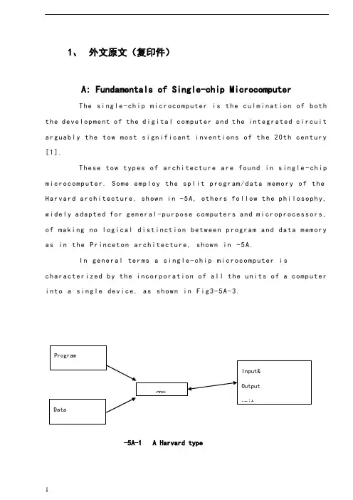
1、外文原文(复印件)A: Fundamentals of Single-chip MicrocomputerTh e si ng le-ch i p mi cr oc om pu ter is t he c ul mi nat i on o f bo th t h e d ev el op me nt o f th e d ig it al com p ut er an d t he int e gr at ed ci rc ui ta r gu ab ly th e t ow m os t s i gn if ic ant i nv en ti on s o f t h e 20t h c en tu ry[1].Th es e to w typ e s of a rc hi te ctu r e ar e fo un d i n s in gl e-ch ip m i cr oc om pu te r. So m e em pl oy t he sp l it p ro gr am/d ata me mo ry o f th e H a rv ar d ar ch it ect u re, sh ow n i n -5A, ot he rs fo ll ow th e ph i lo so ph y, w i de ly a da pt ed fo r g en er al-p ur pos e c om pu te rs an d m i cr op ro ce ss or s, o f m a ki ng no lo gi c al di st in ct io n b e tw ee n p ro gr am a n d da t a m em ory a s i n th e Pr in cet o n ar ch it ec tu re,sh ow n in-5A.In g en er al te r ms a s in gl e-chi p m ic ro co mp ut er i sc h ar ac te ri zed b y the i nc or po ra tio n of al l t he uni t s o f a co mp ut er i n to a s in gl e dev i ce, as s ho wn in Fi g3-5A-3.-5A-1 A Harvard type-5A. A conventional Princeton computerFig3-5A-3. Principal features of a microcomputerRead only memory (ROM).R OM i s u su al ly f or th e p er ma ne nt, n o n-vo la ti le s tor a ge o f an a pp lic a ti on s pr og ra m .M an ym i cr oc om pu te rs an d mi cr oc on tr ol le r s a re in t en de d fo r h ig h-v ol ume a p pl ic at io ns a nd h en ce t he e co nom i ca l ma nu fa ct ure of t he d ev ic es r e qu ir es t ha t the co nt en ts o f the pr og ra m me mo ry b e co mm it te dp e rm an en tl y d ur in g th e m an uf ac tu re o f c hi ps . Cl ear l y, th is im pl ie sa ri g or ou s a pp roa c h t o R OM co de d e ve lo pm en t s in ce c ha ng es ca nn otb e m ad e af te r man u fa ct ur e .T hi s d e ve lo pm en t pr oce s s ma y in vo lv e e m ul at io n us in g a s op hi st ic at ed deve lo pm en t sy st em w i th a ha rd wa re e m ul at io n ca pa bil i ty a s we ll a s th e u se of po we rf ul so ft wa re t oo ls.So me m an uf act u re rs p ro vi de ad d it io na l RO M opt i on s byi n cl ud in g i n th ei r ra ng e de vi ce s wi th (or i nt en de d fo r us e wi th) u s er pr og ra mm ab le m em or y. Th e s im p le st of th es e i s us ua ll y d ev ice w h ic h ca n op er ate in a m ic ro pr oce s so r mo de b y usi n g so me o f th e i n pu t/ou tp ut li ne s as a n ad dr es s an d da ta b us f or acc e ss in g e xt er na l m e mo ry. T hi s t ype o f d ev ic e c an b e ha ve fu nc ti on al l y a s t he si ng le c h ip mi cr oc om pu te r fr om wh ic h i t i s de ri ve d a lb eit w it h r es tr ic ted I/O an d a mo di fie d e xt er na l ci rcu i t. T he u se o f t h es e RO Ml es sd e vi ce s is c om mo n e ve n in p ro du ct io n c ir cu it s wh er e t he v ol um e do es n o t ju st if y th e d e ve lo pm en t co sts of c us to m on-ch i p RO M[2];t he re c a n st il l b e a si g ni fi ca nt s a vi ng in I/O a nd ot he r c hi ps co mp ar ed t o a c on ve nt io nal mi cr op ro ce ss or b as ed c ir cu it. M o re e xa ctr e pl ac em en t fo r RO M d ev ic es c an b e o bt ai ne d in t he f o rm o f va ri an ts w i th 'pi gg y-ba ck'EP RO M(Er as ab le p ro gr am ma bl e ROM)s oc ke ts o rd e vi ce s w it h EP ROM i ns te ad o f R OM 。
电气工程及其自动化专业外文文献英文文献外文翻译方面
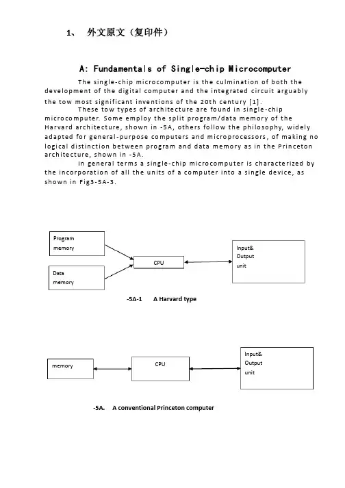
1、 外文原文(复印件)A: Fundamentals of Single-chip MicrocomputerT h e sin gle -ch ip mi c ro co m p u t e r is t h e cu lm in at io n of b ot h t h e d e ve lo p me nt of t h e d ig ita l co m p u t e r a n d t h e i nte g rated c ircu it a rgu ab l y t h e to w mo st s ign if i cant i nve nt i o n s of t h e 20t h c e nt u ry [1].T h ese to w t yp e s of arch ite ct u re are fo u n d in s in gle -ch ip m i cro co m p u te r. S o m e e mp l oy t h e sp l it p ro gra m /d at a m e m o r y of t h e H a r va rd arch ite ct u re , s h o wn in -5A , ot h e rs fo l lo w t h e p h i lo so p hy, wid e l y ad a p ted fo r ge n e ral -p u rp o se co m p u te rs an d m i cro p ro ce ss o rs , of m a kin g n o l o g i ca l d i st in ct i o n b et we e n p ro gra m an d d ata m e m o r y as in t h e P rin c eto n a rch ite ct u re , sh o wn in -5A.In ge n e ra l te r m s a s in g le -ch ip m ic ro co m p u t e r is ch a ra cte r ized b y t h e in co r p o rat io n of all t h e u n its of a co mp u te r into a s in gle d e vi ce , as s h o w n in F i g3-5A-3.-5A-1A Harvard type-5A. A conventional Princeton computerProgrammemory Datamemory CPU Input& Output unitmemoryCPU Input& Output unitResetInterruptsPowerFig3-5A-3. Principal features of a microcomputerRead only memory (ROM).RO M is u su a l l y fo r t h e p e r m an e nt , n o n -vo lat i le sto rage of an ap p l i cat io n s p ro g ram .M a ny m i c ro co m p u te rs a n d m i cro co nt ro l le rs are inte n d ed fo r h i gh -vo lu m e ap p l i cat io n s a n d h e n ce t h e e co n o m i cal man u fa c t u re of t h e d e vi ces re q u ires t h at t h e co nt e nts of t h e p ro gra m me mo r y b e co mm i ed p e r m a n e nt l y d u r in g t h e m a n u fa ct u re of c h ip s . C lea rl y, t h i s imp l ies a r i go ro u s ap p ro a ch to ROM co d e d e ve lo p m e nt s in ce ch an ges can n o t b e mad e af te r m an u fa ct u re .T h i s d e ve l o p m e nt p ro ces s m ay i nvo l ve e mu l at i o n u sin g a so p h ist icated d e ve lo p m e nt syste m wit h a h ard wa re e mu l at i o n capab i l it y as we ll as t h e u s e of p o we rf u l sof t war e to o l s.So m e m an u fa ct u re rs p ro vi d e ad d it i o n a l ROM o p t io n s b y in clu d in g in t h e i r ran ge d e v ic es w it h (o r inte n d ed fo r u s e wit h ) u se r p ro g ram m a b le m e mo r y. T h e s im p lest of t h e se i s u su a l l y d e v i ce wh i ch can o p e rat e in a m i cro p ro ce s so r mo d e b y u s in g s o m e of t h e in p u t /o u t p u t l in es as an ad d res s a n d d ata b u s fo r a cc es sin g exte rn a l m e m o r y. T h is t yp e o f d e vi ce can b e h ave f u n ct i o n al l y as t h e s in gle ch ip m i cro co m p u t e r f ro m wh i ch it i s d e ri ved a lb e it wit h re st r icted I/O an d a m o d if ied exte rn a l c ircu it. T h e u s e of t h e se RO M le ss d e vi ces i s co mmo n e ve n in p ro d u ct io n circu i ts wh e re t h e vo lu m e d o e s n ot ju st if y t h e d e ve lo p m e nt co sts of cu sto m o n -ch ip ROM [2];t h e re ca n st i ll b e a si gn if i cant sav in g in I/O an d o t h e r ch ip s co m pared to a External Timing components System clock Timer/ Counter Serial I/O Prarallel I/O RAM ROMCPUco nve nt io n al m i c ro p ro ces so r b ased circ u it. M o re exa ct re p l a ce m e nt fo rRO M d e v ice s can b e o b tain ed in t h e fo rm of va ria nts w it h 'p i g g y-b a c k'E P ROM(E rasab le p ro gramm ab le ROM )s o cket s o r d e v ice s w it h E P ROMin stead of ROM 。
电气工程的外文文献(及翻译)

电气工程的外文文献(及翻译)文献一:Electric power consumption prediction model based on grey theory optimized by genetic algorithms本文介绍了一种基于混合灰色理论与遗传算法优化的电力消耗预测模型。
该模型使用时间序列数据来建立模型,并使用灰色理论来解决数据的不确定性问题。
通过遗传算法的优化,模型能够更好地预测电力消耗,并取得了优异的预测结果。
此模型可以在大规模电力网络中使用,并具有较高的可行性和可靠性。
文献二:Intelligent control for energy-efficient operation of electric motors本文研究了一种智能控制方法,用于电动机的节能运行。
该方法提供了一种更高效的控制策略,使电动机能够在不同负载条件下以较低的功率运行。
该智能控制使用模糊逻辑方法来确定最佳的控制参数,并使用遗传算法来优化参数。
实验结果表明,该智能控制方法可以显著降低电动机的能耗,节省电能。
文献三:Fault diagnosis system for power transformers based on dissolved gas analysis本文介绍了一种基于溶解气体分析的电力变压器故障诊断系统。
通过对变压器油中的气体样品进行分析,可以检测和诊断变压器内部存在的故障类型。
该系统使用人工神经网络模型来对气体分析数据进行处理和分类。
实验结果表明,该系统可以准确地检测和诊断变压器的故障,并有助于实现有效的维护和管理。
文献四:Power quality improvement using series active filter based on iterative learning control technique本文研究了一种基于迭代研究控制技术的串联有源滤波器用于电能质量改善的方法。
自动化专业中英文对照外文翻译文献
中英文对照外文翻译Automation of professional developmentAutomation in the history of professional development, "industrial automation" professional and "control" professional development of the two main line, "industrial automation" professional from the first "industrial enterprises electrified" professional.In the 1950s, the New China was just founded, the 100-waste question, study the Soviet Union established system of higher education, Subdivision professional. Corresponding to the country in the construction of industrial automation and defense, military construction in automatic control, successively set up the "electrification of industrial enterprises" professional and "control" professional (at that time in many schools, "Control" professional secrecy is professional) . After several former professional name of evolution (see below), and gradually develop into a "biased towards applications, biased towards strong," Automation, and the latter to maintain professional name of "control" basically unchanged (in the early days also known as the "automatic learning And remote learning, "" Automatic Control System "professional), and gradually develop into a" biased towards theory, biased towards weak, "the automation professional, and come together in 1995, merged into aunified" automatic "professional . In 1998, according to the Ministry of Education announced the latest professional undergraduate colleges and universities directory, adjusted, the merger of the new "automated" professional include not only the original "automatic" professional (including "industrial automation" professional and "control" professional ), Also increased the "hydraulic transmission and control of" professional (part), "electrical technology" professional (part) and "aircraft guidance and control of" professional (part).Clearly, one of China's automation professional history of the development of China's higher education actually is a new development of the cause of a microcosm of the history, but also the history of New China industrial development of a miniature. Below "industrial automation" professional development of the main line of this example, a detailed review of its development process in the many professional name change (in real terms in the professional content changes) and its industrial building at the time of the close relationship.First a brief look at the world and China's professional division history. We know that now use the professional division is largely from the 19th century to the beginning of the second half of the first half of the 20th century stereotypes of the engineering, is basically industry (products) for the objects to the division, they have been the image of people Known as the "industry professionals" or "trade associations." At present the international education system in two categories, with Britain and the United States as the representative of the education system not yet out of "industry professionals" system, but has taken the "generalist" the road of education and the former Soviet Union for Europe (close to the Soviet Union) as the representative The education system, at the beginning of theimplementation of "professionals" education, professional-very small, although reforms repeatedly, but to the current "industry professionals" are still very obvious characteristics.In the 1950s, just after the founding of New China, a comprehensive study and the Soviet Union and sub-professional very small; Since reform and opening up, only to Britain and the United States to gradually as the representative of the education system to move closer, and gradually reduce the professional, the implementation of "generalist" education through a number of professional Restructuring and merger (the total number of professionals from the maximum of 1,343 kinds of gradually reducing the current 249 kinds), although not out of "industry professionals" and "Mei Ming," but many of the colleges and universities, mostly only one of a Professional, rather than the past more than a professional.Before that, China's first professional automation from the National University in 1952 when the first major readjustment of the establishment of professional - electrified professional industrial enterprises. At that time, the Soviet Union assistance to the construction of China's 156 large industrial enterprises, automation of much-needed electrical engineering and technical personnel, and such professional and technical personnel training, and then was very consistent with China's industrial construction. By the 1960s, professional name changed to "industrial electric and automation," the late 1970s when to resume enrollment "Electric Industrial Automation" professional. This is not only professional name changes, but has its profound meaning, it reflects China's industries from "electrified" step by step to the "automatic" into the real history and that part of the development trend of China's automation professional reflects how urgent countries Urgent for the country'seconomic construction services that period of history and development of real direction.1993, after four years of the third revision of the undergraduate professional directories, the State Education Commission issued a call "system integrity, more scientific and reasonable, the harmonization of norms," the "ordinary professional directory of undergraduate colleges and universities." "Electric Industrial Automation" and "production process automation" merger of the two professional electrician to set up a kind of "industrial automation" professional, by the then Ministry of Industry Machinery centralized management colleges and universities to set up industrial automation teaching guide at the Commission, responsible for the "Industrial Automation "professional teaching and guiding work at the same time," Control "was attributable to the professional category of electronic information, the then Ministry of Industry of electronic centralized management control to set up colleges and universities teaching guide at the Commission, responsible for the" control " Professional teaching guide our work. After the professional adjustment, further defined the "industrial automation" professional and "control" professional "- both strong and weak, hardware and software into consideration and control theory and practical system integration, and the movement control, process control and other targets of control "The common characteristics with the training objectives, but also the basic set of" industrial automation "biased towards strong, professional, biased towards applications," Control "professional biased towards weak, biased towards the theory of professional characteristics and pattern of division of labor. 1995, the State Education Commission promulgated the "(University) undergraduate engineering leading professional directory", the electrical category "industrialautomation" professional and the original electronic information such as "control" of professional electronic information into a new category of "automatic" professional . As this is the leading professional directory, are not enforced, coupled with general "industrial automation" strong or weak, both professional "into" a weak professional category of electronic information is not conducive to professional development and thus many Schools remain "industrial automation" professional and "control" the situation of professional co-exist. Since 1996 more, again commissioned by the Ministry of National Education Ministry of Industry and electronic machinery industries of other parts of the establishment of the new session (second session) centralized management guidance at the University Teaching Commission, making the leading professionals have not been effective Implemented.1998, to meet the country's economic construction of Kuan Koujing personnel training needs, further consolidation of professional and international "generalist" education track by the Ministry of Education announced a fourth revision of the latest "Universities Undergraduate Catalog." So far in the use of the directory, the total number of professionals from the third amendments to the 504 kinds of substantially reduced to 249 species, the original directory is strong, professional electrician and a weak professional category such as electronics and information into categories Electric power, the unity of Information, a former electrician at the same time kind of "industrial automation" professional and the type of electronic information "control" professional formal merger, together with the "hydraulic transmission and control of" professional (part) , "Electric technology" professional (part) and "aircraft guidance and controlof" professional (part), the composition of the new (enforcement) are electrical information such as "automatic" professional. According to statistics, so far the country has more than 200 colleges and universities set up this kind of "automatic" professional. If the name of automation as part of their professional expertise (such as "electrical engineering and automation," "mechanical design and manufacturing automation," "agricultural mechanization and automation" and other professionals) included Automation has undoubtedly is the largest in China A professional.Of the characteristics of China's automation professional:Recalling China's professional history of the development of automation, combined with the corresponding period of the construction of China's national economy to the demand for automation and automated the development of the cause, it is not difficult to sum up following professional characteristics:(1) China's automation professional is not only a relatively long history (since 1952 have been more than 50 years), and from the first day of the establishment of professional automation, has been a professional one of the countries in urgent need, therefore the number of students has also been The largest and most employers welcome the allocation of the professional one.(2) China's automation is accompanied by a professional from the electrification of China's industrial automation step by step to the development of stable development, professional direction and the main content from the first prominent electrified "the electrification of industrial enterprises" step by step for the development of both the electric and automation " Industrial electric and automation ", highlighting the electrical automation" Electric Industrial Automation "and prominent automation" industrial automation ", then the merger of professional education reform in1995 and" control "of professional content into a broader" automated " Professional. From which we can see that China's automation professional Although the initial study in the Soviet education system established under the general environment, but in their development and the Soviet Union or the United States and Britain did not copy the mode, but with China's national conditions (to meet national needs for The main goal) from the innovation and development of "cross-industry professionals," features the professional.自动化专业的发展自动化专业的发展历史中,有“工业自动化”专业与“自动控制”专业两条发展主线,其中“工业自动化”专业最早源于“工业企业电气化”专业。
电气工程及其自动化 外文翻译 外文文献 英文文献 电力系统的简介
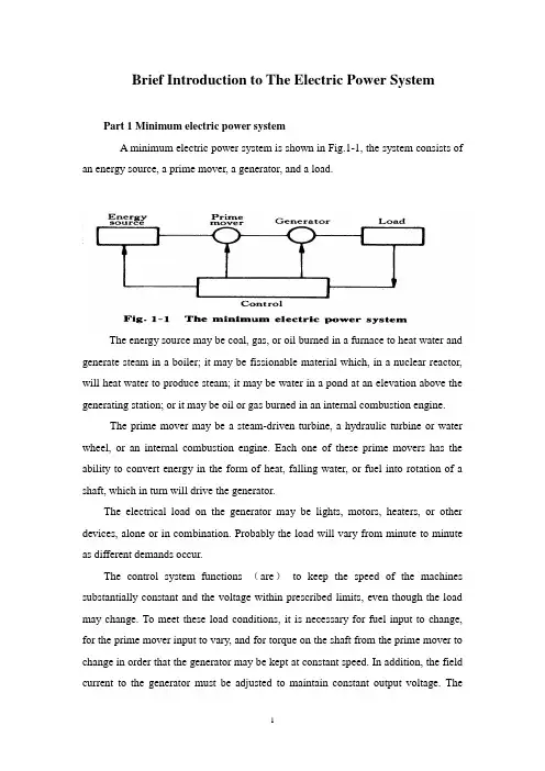
Brief Introduction to The Electric Power SystemPart 1 Minimum electric power systemA minimum electric power system is shown in Fig.1-1, the system consists of an energy source, a prime mover, a generator, and a load.The energy source may be coal, gas, or oil burned in a furnace to heat water and generate steam in a boiler; it may be fissionable material which, in a nuclear reactor, will heat water to produce steam; it may be water in a pond at an elevation above the generating station; or it may be oil or gas burned in an internal combustion engine.The prime mover may be a steam-driven turbine, a hydraulic turbine or water wheel, or an internal combustion engine. Each one of these prime movers has the ability to convert energy in the form of heat, falling water, or fuel into rotation of a shaft, which in turn will drive the generator.The electrical load on the generator may be lights, motors, heaters, or other devices, alone or in combination. Probably the load will vary from minute to minute as different demands occur.The control system functions (are)to keep the speed of the machines substantially constant and the voltage within prescribed limits, even though the load may change. To meet these load conditions, it is necessary for fuel input to change, for the prime mover input to vary, and for torque on the shaft from the prime mover to change in order that the generator may be kept at constant speed. In addition, the field current to the generator must be adjusted to maintain constant output voltage. Thecontrol system may include a man stationed in the power plant who watches a set of meters on the generator output terminals and makes the necessary adjustments manually. In a modern station, the control system is a servomechanism that senses generator-output conditions and automatically makes the necessary changes in energy input and field current to hold the electrical output within certain specifications..Part 2 More Complicated SystemsIn most situations the load is not directly connected to the generator terminals. More commonly the load is some distance from the generator, requiring a power line connecting them. It is desirable to keep the electric power supply at the load within specifications. However, the controls are near the generator, which may be in another building, perhaps several miles away.If the distance from the generator to the load is considerable, it may be desirable to install transformers at the generator and at the load end, and to transmit the power over a high-voltage line (Fig.1-2). For the same power, the higher-voltage line carries less current, has lower losses for the same wire size, and provides more stable voltage.In some cases an overhead line may be unacceptable. Instead it may be advantageous to use an underground cable. With the power systems talked above, the power supply to the load must be interrupted if, for any reason, any component of the system must be moved from service for maintenance or repair. Additional system load may require more power than the generator can supply. Another generator with its associated transformers and high-voltage line might be added.It can be shown that there are some advantages in making ties between the generators (1) and at the end of the high-voltage lines (2 and 3), as shown in Fig.1-3. This system will operate satisfactorily as long as no trouble develops or no equipmentneeds to be taken out of service.The above system may be vastly improved by the introduction of circuit breakers, which may be opened and closed as needed. Circuit breakers added to the system, Fig.1-4, permit selected piece of equipment to switch out of service without disturbing the remainder of system. With this arrangement any element of the system may be deenergized for maintenance or repair by operation of circuit breakers.Of course, if any piece of equipment is taken out of service, then the total load must be carried by the remaining equipment. Attention must be given to avoid overloads during such circumstances. If possible, outages of equipment are scheduled at times when load requirements are below normal.Fig.1-5 shows a system in which three generators and three loads are tied together by three transmission lines. No circuit breakers are shown in this diagram, although many would be required in such a system.Part 3 Typical System LayoutThe generators, lines, and other equipment which form an electric system are arranged depending on the manner in which load grows in the area and may be rearranged from time to time.However, there are certain plans into which a particular system design may be classified. Three types are illustrated: the radial system, the loop system, and the network system. All of these are shown without the necessary circuit breakers. In each of these systems, a single generator serves four loads.The radial system is shown in Fig.1-6. Here the lines form a “tree” spreading out from the generator. Opening any line results in interruption of power to one or more of the loads.The loop system is illustrated in Fig.1-7. With this arrangement all loads may be served even though one line section is removed from service. In some instances during normal operation, the loop may be open at some point, such as A. In case a line section is to be taken out, the loop is first closed at A and then the line section removed. In this manner no service interruptions occur.Fig.1-8 shows the same loads being served by a network. With this arrangement each load has two or more circuits over which it is fed.Distribution circuits are commonly designed so that they may be classified as radial or loop circuits. The high-voltage transmission lines of most power systems are arranged as network. The interconnection of major power system results in networks made up by many line sections.Part 4 Auxiliary EquipmentCircuit breakers are necessary to deenergize equipment either for normal operation or on the occurrence of short circuits. Circuit breakers must be designed to carry normal-load currents continuously, to withstand the extremely high currents that occur during faults, and to separate contacts and clear a circuit in the presence of fault. Circuit breakers are rated in terms of these duties.When a circuit breaker opens to deenergize a piece of equipment, one side of the circuit breaker usually remains energized, as it is connected to operating equipment. Since it is sometimes necessary to work on the circuit breaker itself, it is also necessary to have means by which the circuit breaker may be completely disconnected from other energized equipment. For this purpose disconnect switches are placed in series with the circuit breakers. By opening these disconnectors, thecircuit breaker may be completely deenergized, permitting work to be carried on in safety.Various instruments are necessary to monitor the operation of the electric power system. Usually each generator, each transformer bank, and each line has its own set of instruments, frequently consisting of voltmeters, ammeters, wattmeters, and varmeters.When a fault occurs on a system, conditions on the system undergo a sudden change. V oltages usually drop and currents increase. These changes are most noticeable in the immediate vicinity of fault. On-line analog computers, commonly called relays, monitor these changes of conditions, make a determination of which breaker should be opened to clear the fault, and energize the trip circuits of those appropriate breakers. With modern equipment, the relay action and breaker opening causes removal of fault within three or four cycles after its initiation.The instruments that show circuit conditions and the relays that protect the circuits are not mounted directly on the power lines but are placed on switchboards in a control house. Instrument transformers are installed on the high-voltage equipment, by means of which it is possible to pass on to the meters and relays representative samples of the conditions on the operating equipment. The primary of a potential transformer is connected directly to the high-voltage equipment. The secondary provides for the instruments and relays a voltage which is a constant fraction of voltage on the operating equipment and is in phase with it;similarly, a current transformer is connected with its primary in the high-current circuit. The secondary winding provides a current that is a known fraction of the power-equipment current and is in phase with it.Bushing potential devices and capacitor potential devices serve the same purpose as potential transformers but usually with less accuracy in regard to ratio and phase angle.中文翻译:电力系统的简介第一部分:最小电力系统一个最小电力系统如图1-1所示,系统包含动力源,原动机,发电机和负载。
电气工程及其自动化专业毕业论文外文翻译
本科毕业设计(论文)中英文对照翻译院(系部)工程学院专业名称电气工程及其自动化年级班级 11级2班学生姓名蔡李良指导老师赵波Infrared Remote Control SystemAbstractRed outside data correspondence the technique be currently within the scope of world drive extensive usage of a kind of wireless conjunction technique, drive numerous hardware and software platform support。
Red outside the transceiver product have cost low,small scaled turn, the baud rate be quick,point to point SSL, be free from electromagnetism thousand Raos etc. characteristics,can realization information at dissimilarity of the product fast,convenience,safely exchange and transmission, at short distance wireless deliver aspect to own very obvious of advantage。
Along with red outside the data deliver a technique more and more mature, the cost descend, red outside the transceiver necessarily will get at the short distance communication realm more extensive of application.The purpose that design this s ystem is transmit customer’s operation information with infrared rays for transmit media, then demodulate original signal with receive circuit。
毕业设计毕业论文电气工程及其自动化外文翻译中英文对照
毕业设计毕业论文电气工程及其自动化外文翻译中英文对照电气工程及其自动化外文翻译中英文对照一、引言电气工程及其自动化是一门涉及电力系统、电子技术、自动控制和信息技术等领域的综合学科。
本文将翻译一篇关于电气工程及其自动化的外文文献,并提供中英文对照。
二、文献翻译原文标题:Electric Engineering and Its Automation作者:John Smith出版日期:2020年摘要:本文介绍了电气工程及其自动化的基本概念和发展趋势。
首先,介绍了电气工程的定义和范围。
其次,探讨了电气工程在能源领域的应用,包括电力系统的设计和运行。
然后,介绍了电气工程在电子技术领域的重要性,包括电子设备的设计和制造。
最后,讨论了电气工程与自动控制和信息技术的结合,以及其在工业自动化和智能化领域的应用。
1. 介绍电气工程是一门研究电力系统和电子技术的学科,涉及发电、输电、配电和用电等方面。
电气工程的发展与电力工业的发展密切相关。
随着电力需求的增长和电子技术的进步,电气工程的重要性日益凸显。
2. 电气工程在能源领域的应用电气工程在能源领域的应用主要包括电力系统的设计和运行。
电力系统是由发电厂、输电线路、变电站和配电网络等组成的。
电气工程师负责设计和维护这些设施,以确保电力的可靠供应。
3. 电气工程在电子技术领域的重要性电气工程在电子技术领域的重要性体现在电子设备的设计和制造上。
电子设备包括电脑、手机、电视等消费电子产品,以及工业自动化设备等。
电气工程师需要掌握电子电路设计和数字信号处理等技术,以开发出高性能的电子设备。
4. 电气工程与自动控制和信息技术的结合电气工程与自动控制和信息技术的结合是电气工程及其自动化的核心内容。
自动控制技术可以应用于电力系统的运行和电子设备的控制,以提高系统的稳定性和效率。
信息技术则可以用于数据采集、处理和传输,实现对电力系统和电子设备的远程监控和管理。
5. 电气工程在工业自动化和智能化领域的应用电气工程在工业自动化和智能化领域的应用越来越广泛。
电气自动化英文文献
电气自动化英文文献Electrical Automation: A Comprehensive Analysis.Introduction.Electrical automation is the use of automated systems to control electrical processes in various industries. It encompasses the design, implementation, and maintenance of automated systems to enhance efficiency, safety, and productivity. This technology finds applications in numerous sectors, including manufacturing, energy, healthcare, transportation, and residential settings.Components of Electrical Automation Systems.1. Sensors: Detects and measures various physical parameters such as temperature, pressure, flow, and position.2. Controllers: Analyzes sensor data, makes decisions,and activates actuators based on programmed instructions.3. Actuators: Physical devices that perform actions in response to controller commands, such as opening valves, starting motors, or moving conveyors.4. Communication Network: Connects sensors, controllers, and actuators, enabling data exchange and coordination.5. Human-Machine Interface (HMI): Provides an interface for operators to interact with the automated system and monitor its performance.Benefits of Electrical Automation.1. Increased Efficiency: Automates repetitive tasks, reducing human errors and improving productivity.2. Enhanced Safety: Eliminates the need for manual intervention in hazardous environments, reducing the riskof accidents.3. Improved Quality: Ensures consistent and accurate control of processes, leading to higher quality products.4. Reduced Costs: Optimizes energy usage, reduces maintenance expenses, and eliminates labor costs associated with manual operations.5. Increased Flexibility: Allows for rapid reconfiguration of automated systems to adapt to changing requirements or product specifications.Applications of Electrical Automation.1. Manufacturing: Automated assembly lines, robotic workstations, and inventory management systems.2. Energy: Smart grids, renewable energy systems, and energy efficiency management.3. Healthcare: Automated medical devices, patient monitoring systems, and hospital automation.4. Transportation: Vehicle control systems, traffic management systems, and automated logistics.5. Residential Settings: Home automation systems for lighting, temperature control, and security.Challenges in Electrical Automation.1. Complexity: Designing and integrating complex automated systems requires advanced engineering skills and specialized software.2. Cybersecurity: Automated systems can be vulnerable to cyberattacks, requiring robust security measures.3. Maintenance and Troubleshooting: Regular maintenance and skilled technicians are crucial to ensure thereliability and uptime of automated systems.4. Initial Investment: Implementing electrical automation systems can involve significant upfront costs, requiring careful planning and justification of theinvestment.5. Displacement of Workforce: Automation can lead to job displacement, necessitating training and upskilling programs for displaced workers.Future Trends in Electrical Automation.1. Artificial Intelligence (AI) and Machine Learning: Enabling predictive analytics, self-optimization, and autonomous decision-making.2. Internet of Things (IoT): Connecting automated systems to the internet for remote monitoring, data analytics, and cloud-based services.3. Digital Twins: Creating virtual models of automated systems for simulation, testing, and real-time monitoring.4. Edge Computing: Processing data on-site to reduce latency and improve system responsiveness.5. Increased Adoption in Emerging Industries: Expanding applications in sectors such as agriculture, mining, and construction.Conclusion.Electrical automation is a transformative technology that has revolutionized various industries, driving efficiency, safety, quality, and cost savings. As technology continues to advance, the applications and possibilities of electrical automation are bound to grow exponentially, contributing to further innovation and progress across numerous sectors.。
电气自动化 单片机 外文文献 英文文献 外文翻译 中英对照
Single-chip1.The definition of a single-chipSingle-chip is an integrated on a single chip a complete computer system .Even though most of his features in a small chip,but it has a need to complete the majority of computer components:CPU,memory,internal and external bus system,most will have the Core.At the same time,such as integrated communication interfaces,timers,real-time clock and other peripheral equipment.And now the most powerful single-chip microcomputer system can even voice ,image,networking,input and output complex system integration on a single chip.Also known as single-chip MCU(Microcontroller),because it was first used in the field of industrial control.Only by the single-chip CPU chip developed from the dedicated processor. The design concept is the first by a large numberof peripherals and CPU in a single chip,the computer system so that smaller,more easily integrated into the complex and demanding on the volume control devices.INTEL the Z80 is one of the first design in accordance with the idea of the processor,From then on,the MCU and the development of a dedicated processor parted ways.Early single-chip 8-bit or all the four.One of the most successful is INTELs 8031,because the performance of a simple and reliable access to a lot of good praise.Since then in 8031to develop a single-chip microcomputer system MCS51 series.based on single-chip microcomputer system of the system is still widely used until now.As the field of industrial control requirements increase in the beginning of a 16-bit single-chip,but not ideal because the price has not been very widely used.After the90s with the big consumer electronics product development,single-chip technology is a huge improvement.INTEL i960 series with subsequent ARM in particular ,a broad range of application,quickly replaced by 32-bit single-chip 16-bit single-chip performance has been the rapid increase in processing power compared to the 80s to raise a few hundred times.At present,the high-end 32-bit single-chip frequency over 300MHz,the performance of the mid-90s close on the heels of a special processor,while the ordinary price of the model dropped to one U.S dollars,the most high-end models,only 10 U.S dollars.Contemporary single-chip microcomputer system is no longer only the bare-metal environment in the development and use of a large number of dedicated embedded operating system is widely used in the full range of single-chip microcomputer.In PDAs and cellphones as the coreprocessing of high-end single-chip or even a dedicated direct access to Windows and Linux operating systems.More than a dedicated single-chip processor suitable for embedded systems,so it was up to the application.In fact the number of single-chip is the worlds largest computer.Modern human life used in almost every piece of electronic and mechanical products will have a single-chip integration.Phone,telephone,calculator,home applicances,electronic toys,handheld computers and computer accessories such as a mouse in the Department are equipped with 1-2 single chip.And personal computers also have a large number of single-chip microcomputer in the workplace.Vehicles equipped with more than 40 Department of the general single-chip ,complex industrial control systems and even single-chip may have hundreds of work at the same time!SCM is not only far exceeds the number of PC and other integrated computing,even more than the number of human beings.2.single-chip introducedSingle-chip,also known as single-chip microcontroller,it is not the completion of a logic function of the chip,but a computer system integrated into a chip.Speaking in general terms: a single chip has become a computer .Its small size,light weight,cheap,for the learning,application and development of facilities provided .At the same time,learning to use the principle of single-chip computer to understand and structure the best choice.Single-chip and computer use is also similar to the module,such as CPU,memory,parallel bus, as well as the role and the same hard memory,is it different from the performance of these components are relatively weak in our home computer a lot,but the price is low ,there is generally no more than 10yuan,,can use it to make some control for a class of electrical work is not very complex is sufficient.We are using automatic drum washing machines, smoke hood,VCD and so on inside the home appliances can see its shadow! It is mainly as part of the core components of the control.It is an online real-time control computer,control-line is at the scene,we need to have a stronger anti-interference ability,low cost,and this is off-line computer(such as home PC)The main difference.By single-chip process,and can be amended.Through different procedures to achieve different functions,in particular the special unique features,this is the need to charge other devices can do a great effort,some of it is also difficult to make great efforts to do so .A function is not very complicated fi the United States the development of the 50s series of 74 or 60 during the CD4000series to get these pure hardware,the circuit must be a big PCB board !However,if the United States if the successful 70s seriesof single-chip market ,the result will be different!Simply because the adoption of single-chip preparation process you can achieve high intelligence,high efficiency and high reliability!Because of cost of single-chip is sensitive,so the dominant software or the lowest level assembly language,which is in addition to the lowest level for more than binary machine code of the language ,since such a low-level so why should we use ?Many of the seniors language has reached a level of visual programming why is it not in use ?The reason is simple ,that is,single-chip computer as there is no home of CPU,also not as hard as the mass storage device.A visualization of small high-level language program,even if there is only one button which will reach the size of dozens of K! For the home PCs hard drive is nothing,but in terms of the single-chip microcomputer is unacceptable.Single-chip in the utilization of hardware resources have to do very high ,so the compilation of the original while still in heavy use .The same token ,if the computer giants operating system and appplications run up to get the home PC,homePCcan not afford to sustain the same.It can be said that the twentieth century across the three “power”of the times,that is ,the electrical era,the electronic age and has now entered the computer age. However ,such a computer,usually refers to a personal computer,or PC.It consisits of the host ,keyboards,displays .And other components.There is also a type of computer,not how most people are familiar with . This computer is smart to give a variety of mechanical single-chip(also known as micro-controller).As the name suggests,these computer systems use only the minimum of an integrated circuit to make a simple calculation and control. Because of its small size,are usually charged with possession of machine in the “belly”in. It in the device,like the human mind plays a role, it is wrong,the entire device was paralyzed .Now,this single chip has a very wide field of use,such as smart meters,real-time industrial control,communications equipment,navigation systems,and household appliances. Once a variety of products with the use of the single-chip ,will be able to play so that the effectiveness of product upgrading,product names often adjective before the word “intelligent”,such as was hing machines and so intelligent.At present,some technical personnel of factories or other amateur electrtonics developers from engaging in certain products ,not the circuit is too complex ,that is functional and easy to be too simple imitation.The reason may be the product not on the cards or the use of single-chip programmable logic device on the other.3.single-chip historysingle-chip 70 was born in the late 20th century,experienced a SCM,MCU,SOC three stages.Single-chip micro-computer 1.SCM that(Single Chip Microcomputer)stage,is mainly a single from to find the best of the best embedded systems architecture.”Innovation model”to be successful,lay the SCM with the general-purpose computers,a completely different path of development . In embedded systems to create an independent development path,Intel Corporation credit.That is 2.MCU microcontroller(Micro Controller Unit)stage,the main direction of technology development: expanding to meet the embedded applications,the target system requirements for the various peripheral circuits and interface circuits,to highlingt the target of intelligent control.It covers all areas related with the objectSystem,therefore,the development of MCU inevitably fall on the heavy electrical,electronics manufacturers. From this point of view ,Intels development gradually MCU has its objective factors.MCU in the development ,the most famous manufacturers when the number of Philips Corporation.Philips in embedded applications for its enormous advantages,the MCS-51 from the rapid deveploment of single-chip micro-computer to the microcontroller.Therefore,when we look back at the path of development of embedded systems,Intel and Philips do not forget the historical merits.3.Single-chip is an independent embedded systems development,to the MCU an important factor in the development stage,is seeking applications to maximize the natural trend .With the mico-electronics technology,IC design,EDA tools development,based on the single-chip SOC design application systems will have greater development. Therefore,the understanding of single-chip micro-computer from a single ,monolithic single-chip microcontroller extends to applications.4.Single-chip applicationsAt present,single-chip microcomputer to infiltrate all areas of our lives,which is very difficult to find the area of almost no traces of single-chip microcomputer.Missile navigation equipment,aircraft control on a variety of instruments,compuer network communications and data transmission,industrial automation,real-time process control and data processing ,are widely used in a variety of smart IC card,limousine civilian security systems,video recorders,cameras,the control of automatic washing machines,as well as program-controllde toys,electronic pet,etc,which are inseparable from the single-chip microcomputer.Not to mention the field of robot automation ,intelligent instrumentation,medical equipment has been. Therefore,the single- chip learning ,development and application to a large number of computer applications and intelligent control of scientists,engineers.Single-chip widely used in instruments and meters,household appliances,medical equipment ,acrospace,specialized equipment and the intellingent management in areas such as process control,generally can be divided into the following areas:1.In the smart application of instrumentationSingle-chip with small size,low power consumption,control,and expansion flexibility , miniaturization and ease of sensors,can be realized,suchvoltage,power,frequency,humidity,temperature,flow,speed,thickness,angle,length,hardness,elemen t,measurement of physical pressure. SCM makes use of digital instrumentation,intelligence,miniaturization and functional than the use of electronic or digital circuitry even stronger.For example,precision measurement equipment(power meter,oscilloscope,and analyzer).2.In the industrial controlMCU can constitute a variety of control systems,data acquisition system.Such as factory assembly line of intelligent management ,intelligent control of the lift ,all kinds of alarm systems ,and computer networks constitute a secondary control system.3.In the applicationof household appliancesIt can be said that almost all home appliances are using the single-chip control,electric rice from favorable,washing machines,refrigerators,air conditioners,color TV and other audio video equipment,and then to the electronic weighing equipment,all kinds ,everywhere.4.On computer networks and communication applications in the field ofGenerally with the modern single-chip communication interface,can be easily carried out with computer carried out with computer data communications,computer networks and in inter-application communications equipment to provide an excellent material conditions,the communications equipment to provide an excellent material condition,from the mobile phone ,telephone , mini-program-controlled switchboards,buiding automated communications system call,the train wireless communications,and then you can see day-to-day work of mobile phones,Mobile communications,such as radios.5.Single-chip in the field of medical equipment applicationsSingle-chip microcomputer in medical devices have a wide range of purpose,such as medical ventilator,various analyzers,monitors,ultrasonic diagnostic equipment and hospital call systems.6.In a variety of large-scale electrical applications of modularSome special single-chip design to achieve a specific function to carry out a variety of modular circuitapplications,without requiring users to understand its internal structure.Integrated single-chip microcomputer such as music ,which seems to be simpleFunctions,a miniature electronic chip in a pure(as distinct from the principle of tape machine),would require a complex similar to the principle of the computer. Such as :music signal to digital form stored in memory(similar to ROM),read out by the microcontroller into analog music signal(similar to the sound card).In large circuits,modular applications that greatly reduces the size ,simplifying the circuit and reduce the damage,error rate ,but also to facilitate the replacement.In addition,single-chip microcomputer in the industrial,commercial,financial,scientific research ,education,defense aerospace and other fields have a wide range of uses.单片机1.单片机定义单片机是一种集成在电路芯片上的完整计算机系统。