光纤FC系列规格书
光纤分路器技术规格书
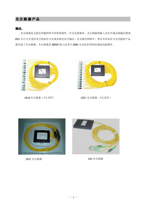
光分路器产品
概述:
光分路器是无源光传输网络中的重要器件,作为无源器件,光分路器将输入光信号通过熔融拉锥或PLC芯片分光等技术手段拓扑分光成多路光信号输出。
在无源光网络中,所有具有拓扑分光功能的产品都安装了光分路器,光分路器是XPON接入技术中ODN分光拓扑网络的基础功能器件。
1X16光分路器(Ф2尾纤)1X32光分路器(Ф2尾纤)
1X32光分路器1X4光分路器
型号编码规则:
VI : 写为XXm ,其中XX 用于描述引出光纤的长度,单位为m ,如2m 表示长度为2米; VII : 写为ΦXX ,其中XX 用于描述引出光纤的外径,单位为mm ,如Φ2表示光纤外径为2mm ; VIII :用于描述光纤的模式,SM 表示单模,MM 表示多模,单模可省略不写。
举例说明:
光分路器 SPL-W (1×8)-FC/PC-1.5m-Ф2 表示1分8拉锥式光分路器,共引出9根1.5米长,直径Ф2的单模尾纤,尾纤连接头类型为FC/PC 。
外形尺寸图:
1X4、2X4、1X8、2X8分光器外形尺寸图(适用于Ф2、Ф3尾纤) 1X16、2X16、1X32、2X32分光器外形尺寸图
(适用于Ф2、Ф3尾纤)
1X4、1X8分光器外形尺寸图(适用于Ф0.9尾纤) 1X16、1X32分光器外形尺寸图(适用于Ф0.9尾纤)
技术指标:
注:不同尾纤直径分光器的封装尺寸参见外形尺寸图
订货指南:
以上仅为部分常用型号,可根据客户要求提供更多型号选择。
FC-500光纤切割器说明书

FC-500FIBER CLEAVER INSTRUCTION MANUALBLADE REPLACEMENT INSTRUCTIONS 1.Open the Cover Plate, and using the 2.0mm hex key, remove the fiber Trash Can.2.Align the Sliding Block so that the blade is centered between the fiber Grips and the two hex screws are exposed.3. Loosen the hex screws near the blade and remove the plastic housing of the Cleaving Slider.4.Using a 2.5mm hex key (not included), remove the two outer hex screws and remove the blade assembly.5. Pop the blade out of the assembly and replace it with a new one.6.Make sure that the orientation of the blade is correct (numbers facing down, position 1 at top)and reassemble the unit. You are now ready to use your FC-500 Fiber Cleaver!3. Gently push the Sliding Block to the back of the unit only once to cleave the fiber.4. Open the Cover Plate and Fiber Clamp and remove the cleaved fiber. Do not allow the face of the fiber to contact any surface.5.Close the Cover Plate, Fiber Clamp, and Fiber Trash Can. If the Trash Can is full, dispose of the contents carefully by tipping them into a separate fiber disposal container.BLADE ADJUSTMENT INSTRUCTIONSBefore You Start - Make sure you have a precision flathead screwdriver on hand. Make sure you only adjust the blade when needed (after it has noticeably dulled).1.Open the Cover Plate, and using the 2.0mm hex key, remove the Fiber Trash Can.2. Using the 1.5mm hex key, loosen the two hex screws on the Sliding Cover.3.Using your precision screwdriver, rotate the blade about a 1/4 of a turn so that the next number on the blade is visible. Blade can be used 3,000 times before needing to be rotated.4.Tighten down the two hex keys on the Sliding Block and assemble the Fiber Trash Can to startusing the FC-500 again.PushOPERATING INSTRUCTIONSBefore You Start - Make sure the fiber trash can is open and the Sliding Block is pushed forward.1.Open the Fiber Clamp and Cover Plate and put bare fiber (≥18mm or ≥0.7”) into the Fiber Holder. Align the stripped jacket of the fiber with the ruler to cleave to specific lengths of fiber.2.Position the fiber so that it is past the Cleaving Blade. Then, close the Fiber Clamp and CoverPlate to hold the fiber in place. Ensure the fiber is straight and even before cleaving.Fiber HolderFiber ClampCover PlateBlade BlockFiber Trash CanSliding BlockCleaving BladeFiber GripsSAFETY & CONTENTSPlease read this instruction manual carefully before operation of this tool and save it for future reference. Store the FC-500 in a dry and dust-free environment. Do not store or use the FC-500 in high temperature places. Do not use excess force when using the fiber cleaver. Regularly clean any dirt on the Fiber Clamp with alcohol. Do not use acetone or another corrosive solvent when cleaning the Fiber Clamp. Consistently clean the fiber box and ensure no dust or oil dirties the slot.。
FC-6R光纤切割机使用说明书

3. Operating proceduresthe fiber coating (e.g. if the cleave length is 16mm) at the 16mm mark on the ruler.Blade carriageLid of single fiber adapterlid of the single fiber adapter. The blade carriage should be in the forward position.OME1126010COptical Fiber CleaverFC-6ROperation ManualThis product has been designed and manufactured to assure personal safety. Improper use can result in bodily injury and serious damage to the fiber cleaver. Please read and observe all warnings instructions given in this operation manual.1. Do not disassemble or lubricate any parts of the cleaver. Doing so can cause serious damage to the cleaver.2. The FC-6R is a precision tool. Do not impact the cleaver by hitting or dropping it. Doing so can cause personal injury and loss of cleaving performance.3. Glass fiber fragments are extremely sharp. Handle with care. Wear safety glasses at all times during cleaving operation for protection from glass fibers.4. Dispose of glass fiber fragments properly.5. The blade of the cleaver is extremely sharp. Do not touch it with bare hands.6. Do not impact the top clamp lever and switching lever. Doing so can cause damage to the levers and loss of cleaving performance.7. Do not attempt to push further the blade carriage which has been in the rear of the cleaver. Doing so can cause loss of cleaving capability and performance. 8. If the cleaver is damaged or a problem occurs, please contact our service department.SpecificationStandard packageOptional accessories / ConsumablesIMPORTANT SAFETY PRECAUTIONSCautionFC-6RS / FC-6RS-CCladding Diameter 125μmFiber CountCoating Diameter Single fiber (0.25 & 0.9mm)Cleave length 5~20mm (0.25mm), 10~20mm (0.9mm) Cleaving position24 positionsBlade rotation function Fixed / Automatic rotation/ Manual rotation Dimensions FC-6RS: 63(W)x77(D)x63(H)mm FC-6RS-C: 100(W)x81(D)x63(H)mm WeightFC-6RS: Approx. 380g FC-6RS-C: Approx. 420gFC-6RM / FC-6RM-CCladding Diameter 125μmFiber CountCoating Diameter Single fiber (0.25 & 0.9mm) Up to 12-fiber ribbon Cleave length 10mmCleaving position24 positionsBlade rotation function Fixed / Automatic rotation / Manual rotation Dimensions FC-6RM: 63(W)x77(D)x63(H)mm FC-6RM-C: 100(W)x81(D)x63(H)mm WeightFC-6RM: Approx. 380g FC-6RM-C: Approx. 420gFC-6RS FC-6RS-CFiber off-cut collector: CU-FC6RFC-6RM FC-6RM-CSingle fiber adapter: AP-FC6MFiber off-cut collector: CU-FC6RFC-6RS FC-6RS-C FC-6RM FC-6RM-C Optical Fiber Cleaver FC-6R 1 pc 1 pc 1 pc 1 pc Carrying case 1 pc 1 pc 1 pc 1 pc Operation Manual1 pc1 pc1 pc1 pcThis symbol indicates explanations about dangerous matters. If users ignore this symbol and handle the cleaver the wrong way, bodily injury anddamage to the cleaver could result.< Single fiber adapter AP-FC6M >Groove for 0.25mm fiberGroove for 0.9mm fiber < Fiber cleaver FC-6RS(-C)/6RM(-C) >AnvilTop clamp leverBlade carriageBladereceptacleClampSwitching lever (Blade rotation)Switching pin(Rear view)Blade rotation mechanismSingle fiber adapterAP-FC6M1The blade carriage should be in the forward position.2: Place the fiber holder in the cleaver. Place the edge of the fiber holder against the edge of the fiber holder receptacle.3: Lower the top clamp lever. Slide the blade carriage to the rear of the cleaver. The fiber will be cleaved.4: Open the top clamp lever. Remove the fiber holder from the cleaver. Lift the off-cut and dispose it properly. (The FC-6RM-C automatically collects an off-cut in the off-cut collector.)Blade carriage4: Lower the top clamp lever. Slide the blade carriage to the rear of the cleaver. The fiber will be cleaved.5: Open the top clamp lever. Then open the lid of the single fiber adapter and lift the newly cleaved fiber. Lift the off-cut and dispose it properly. (The FC-6RS-C automatically collects an off-cut in the off-cut collector.)Fiber coatingBare fiberCleave length Switching of blade rotating operations<Blade rotating operations>Blade rotating operation can be set by bringing the switching pin to a given position.Blade is not rotated.Blade is rotated by approx. 15° with each cleave.The blade is fixed and not rotated.If a certain area of the blade cannot cleave fiber, rotate the blade with “Automatic rotation” or “Manual rotation” option, referring to the next sections.Fixed (Default setting)0 Automatic rotationR 1: As illustrated in the figure below, pull the switching lever to the right and turnFixedAutomatic rotationManual rotationSwitching leverSwitchingpin(Continued to page 3.)3: Close the lid of the single fiber adapter.Switchinglever Switchingpin2Ensure that the blade carriage is completely pushed to therear of the cleaver. Otherwise the blade is not rotated.2: After sliding the blade carriage to make a cleave, push it further to the rear of the cleaver. The bladeEnsure that the blade carriage is completely pushed to the rear of the cleaver. Otherwise the blade is not rotated.Manual rotation1 2: After sliding the blade carriage to make a cleave, push it further to the rear of the cleaver. The blade is automatically rotated by approx. 1: As illustrated in the figure below, pull the switching lever to the right andThe blade is rotated by 1/24 turn (approx. 15°) once. Afterthe rotation, blade rotating operation returns to [ Fixed].0 CautionCaution4. MaintenanceCleaningTo keep excellent cleaving quality, cleaning must be performed after use. Clean the blade edge, the rubber pad of the clamp and the anvil with a cotton ▪ Dust on the blade edge or the clamp might cause loss of cleavingperformance or poor quality of fiber end face. ▪ Do not clean them with any other kind of chemicals.▪ If the top clamp lever is closed leaving an off-cut fiber on the clamp, the rubber pad of the clamp will have a trace of the fiber, causing loss of cleaving performance or poor quality of fiber end face.Clean the fiber holder receptacle and the grooves of the single fiber adapter, too.CautionIf the problem still persists, please contact our service department. If the cleaving problem occurs, the followings are possible causes. (A) The fiber is placed obliquely in the cleaver.↓ Make sure that the fiber is placed straight in the cleaver. (B) The blade height is too high. ↓ Adjust the blade height.(C) Dust or dirt remains on the clamp. ↓ Clean the clamp.(D) Dust or dirt remains on the blade ↓ Clean the blade.(E) Dust or dirt remains on the fiber.↓ Remove the fiber coating and clean the bare fiber again. Poor cleave angle Lip CrackGoodTroubleshootingSwitching leverSwitchingpin3: When the blade carriage is slid back to the front, the switching pin manually.) Thereafter the blade is fixed.(Continued to step 3.)The blade carriage is slid to cleave fiber.The blade carriage is pushed further to the rear of the cleaver.The blade carriage is slid to cleave fiber.The blade carriage is pushed further to the rear of the cleaver.3Maintenance and repair serviceIf the blade is chipped and cannot cleave fiber, rotate the blade in “Manual rotation” and use the cleaver avoiding thechipped area of the blade. For rotating operation, please refer to “Switching of blade rotating operations.”CautionDo not remove the pin which holds the blade and cleaver body. Do not remove the blade rotating mechanism either.The blade will not rotate or the blade height will change, causing loss of cleaving performance.CautionThe FC-6R must be time for maintenance after 1 year of use or when it cannot cleave fiber. (You will be charged for bladereplacement.) Please return it to our service department when the time for maintenance comes.Caution5. Fiber off-cut collectorInstalling off-cut collector1: Open the top clamp lever fully.2: Put the lever pin into the pin hole of the cleaver< Fiber off-cut collector CU-FC6R >FrontLever pinPut the lever pin into the pin hole of the cleaver.3: Ensure that the lever pin and hook fit the cleaver properly.<Top view>(c) 2011 SUMITOMO ELECTRIC INDUSTRIES, LTD.4: Align the screw holes on the cleaver with the screw holes on the off-cut collector.5: Tighten the 3 setscrews. Optimum torque: Approx. 40cNm6: Completed.Tokyo (JAPAN)Sumitomo Electric Industries, Ltd. (Global Business Dept.)Akasaka Center Building, 1-3-13, Motoakasaka, Minato-ku, Tokyo 107-8468, JAPANTel: +81 (0)3 6406 2666/sumitomo-electric-splicersNorth Carolina (U.S.A)Sumitomo Electric Lightwave Corp. 201 South Rogers Lane, Suite 100 Raleigh, NC27610 U.S.A Toll Free No. 800 358 7378 Tel: +1 919 541 8100London (U.K)Sumitomo Electric Europe Ltd.220 Centennial Park, Centennial Avenue, Elstree, Herts, WD6 3SL, U.K. Tel: +44 (0)20 8953 8118 Hong Kong (China)Sumitomo Electric Asia, Ltd. Tel: +852 2576 0080 /Bangkok (Thailand)Sumitomo Electric (Thailand) Limited Tel: +66 (0)2 260 7231 to 5 /SingaporeSumitomo Electric Asia Pacific Pte. Ltd. Tel: +65 6261 3388.sg/Emptying off-cut collectorOff-cut bin1: Remove the off-cut bin from the off-cut collector and dispose of the off-cuts in a proper way.Notice on Sumitomo genuine productsPlease be very cautious of copy products that pretend Sumitomo genuineproducts.The security hologram is a key to identifying Sumitomo genuine products.Caution<Example: FC-6RS >4Dubai (U.A.E.)Middle East office Tel: +971 4 701 7338Gurgaon (India)SEI Trading India Pvt. Ltd. (SETI) Tel: +91 124 4577 470Manila (Philippines)SEI (PHILIPPINES) INCORPORATED Tel: +63 2 811 2755/2756。
fc光纤接头尺寸参数

FC光纤接头尺寸参数一、概述F C光纤接头是一种常用的光纤连接器,用于连接光纤设备和光纤线缆。
了解FC光纤接头的尺寸参数对于光纤网络的设计和维护至关重要。
本文将介绍F C光纤接头的尺寸参数,包括外部尺寸、内部结构和常见规格。
二、外部尺寸F C光纤接头的外部尺寸通常由其连接器外壳的长度和直径表示。
常见的F C光纤接头外壳长度为38.48mm。
接头的直径一般为约10.80mm。
这些尺寸参数可以确保F C光纤接头与其他设备和连接器的兼容性。
三、内部结构F C光纤接头的内部结构包括插芯、套筒和螺纹连接部分。
插芯是用于连接光纤和传输光信号的关键部件,其长度为2.5m m。
套筒则用于保护插芯,并提供插拔的稳定性。
螺纹连接部分用于固定接头,确保连接的牢固性和稳定性。
四、常见规格F C光纤接头的常见规格包括FC/P C、FC/UP C和FC/A PC。
这些规格主要区别在插芯的形状和光的传输效果上。
1.FC/P C:P C表示Ph y si ca lC on ta ct,即物理接触型。
该类型的插芯表面处于光滑状态,能提供较好的连接l os s和反射损耗(R et ur nL os s)性能,适用于一般光纤传输需求。
2.FC/U PC:U PC表示U lt ra Ph ys ic al Co n ta ct,即超物理接触型。
该类型插芯在表面经过精细加工,能提供更低的光损耗和更高的反射损耗性能,适用于对传输质量有较高要求的场景,如光通信和传感。
3.FC/A PC:A PC表示A ng le dP hy si cal C on ta ct,即倾斜物理接触型。
该类型插芯在表面倾斜加工,能进一步减少反射损耗,提供更佳的光传输性能。
适用于对反射损耗要求极高的应用,如有源设备间的连接。
五、总结本文介绍了F C光纤接头的尺寸参数,其中外部尺寸包括长度和直径,内部结构包括插芯、套筒和螺纹连接部分,常见规格包括F C/P C、F C/U PC和F C/AP C。
住友光纤切割刀 FC-6R 使用说明书
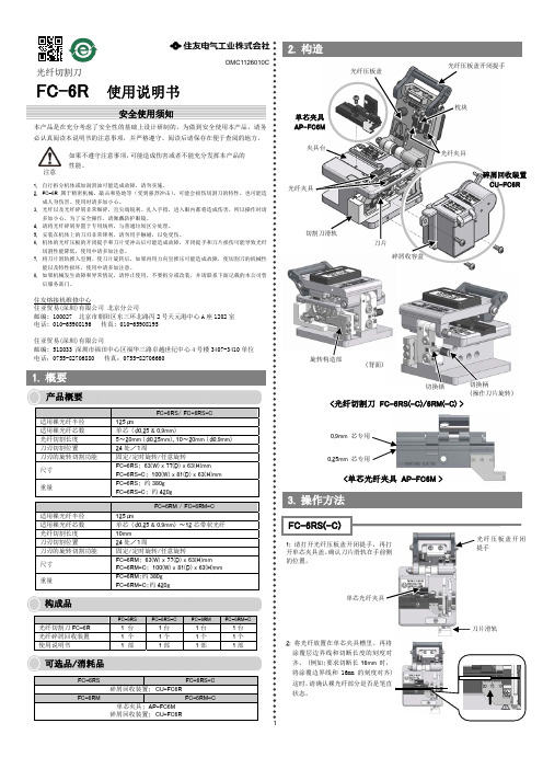
OMC1126010C光纤切割刀FC-6R 使用说明书本产品是在充分考虑了安全性的基础上设计研制的。
为做到安全使用本产品,请务必认真阅读本说明书的注意事项,并严格遵守。
阅读后请保存在便于查阅的地方。
2. 构造0.25mm 芯专用0.9mm 芯专用安全使用须知3. 操作方法2: 将光纤放置在单芯夹具槽里。
再将涂覆层边界线和切断长度的刻度对齐。
(例如:要求切断长16mm 时,将涂覆边界线和16mm 的刻度对齐)这时,请确认裸光纤部分是否是笔直状态。
刀片滑轨光纤压板盖开闭提手单芯光纤夹具FC-6RS(-C)1: 请打开光纤压板盖开闭提手,再打开单芯夹具盖。
确认刀片滑轨在手前侧的位置。
注意如果不遵守注意事项,可能造成伤害或者不能充分发挥本产品的性能。
<光纤切割刀 FC-6RS(-C)/6RM(-C) >枕块光纤压板盖开闭提手切割刀滑轨刀片夹具台光纤夹具切换柄(操作刀片旋转)旋转构造部切换锁(背面)1. 自行拆分机体或加润滑油可能造成故障,请勿实施。
2. FC-6R 属于精密机械。
敲击和坠地等(受到强烈冲击),可能会损伤切割刀的特性,也可能造成人身伤害。
使用时请多加小心。
3. 光纤以及光纤碎屑非常细碎,且尖端锐利。
扎入手指,进入眼内都将造成伤害,所以操作时请多加小心。
为了安全操作,请佩戴防护眼镜。
4. 请将光纤碎屑弃置于专用场所,与普通垃圾区分处理。
5. 安装在机体上的刀刃非常锋利,请勿用手触碰,以免受伤。
6. 机体的光纤压板的开闭提手和刀片受冲击后可能造成故障,开闭提手和刀片损伤可能导致光纤切割性能降低,使用中请多加注意。
7. 将刀片滑轨推入里侧、使刀片旋转后,如果再用力向里推压可能造成故障,使切割刀的机械性能以及特性损坏,使用中请多加注意。
8. 如果机械发生故障和异常情况,请停止使用,不要拆分或改装,并请联系下面记载的本公司售后服务部门。
住友熔接机维修中心住亚贸易(深圳)有限公司 北京分公司邮编: 100027 北京市朝阳区东三环北路丙2号天元港中心A 座1202室 电话*************传真*************住亚贸易(深圳)有限公司邮编: 518033 深圳市福田中心区福华三路卓越世纪中心4号楼3407-3410单位1. 概要产品概要构成品可选品/消耗品FC-6RS/ FC-6RS-C适用裸光纤半径 125μm 适用裸光纤芯数 单芯 (φ0.25 & 0.9mm) 光纤切割长度 5~20mm (φ0.25mm)、10~20mm (φ0.9mm) 刀刃切割位置24处/1周刀刃的旋转切割功能 固定/定时旋转/任意旋转尺寸 FC-6RS: 63(W) x 77(D) x 63(H)mm FC-6RS-C: 100(W) x 81(D) x 63(H)mm 重量FC-6RS: 约380g FC-6RS-C: 约420gFC-6RM / FC-6RM-C适用裸光纤半径 125μm 适用裸光纤芯数 单芯 (φ0.25 & 0.9mm) ~12芯带状光纤 光纤切割长度 10mm刀刃切割位置24处/1周刀刃的旋转切割功能 固定/定时旋转/任意旋转尺寸 FC-6RM: 63(W) x 77(D) x 63(H)mm FC-6RM-C: 100(W) x 81(D) x 63(H)mm 重量FC-6RM:约380g FC-6RM-C:约420gFC-6RSFC-6RS-CFC-6RMFC-6RM-C光纤切割刀FC-6R 1 台 1台 1台 1台 光纤碎屑回收装置 1 个 1个 1个 1个 使用说明书1 部 1部 1部 1部FC-6RSFC-6RS-C碎屑回收装置: CU-FC6RFC-6RMFC-6RM-C 单芯夹具: AP-FC6M 碎屑回收装置: CU-FC6R单芯夹具 AP-FC6M <单芯光纤夹具 AP-FC6M >14: 请关闭光纤压板盖,并且放下光纤开闭提手。
FC皮线光纤快速接续连接器说明书-北
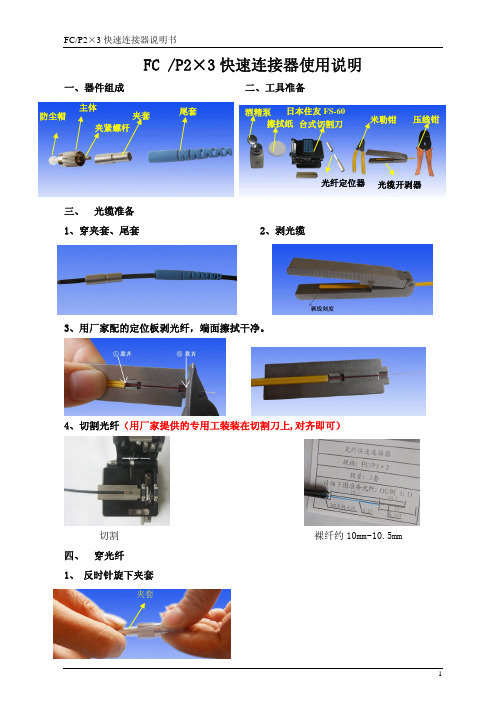
FC /P2×3快速连接器使用说明
一、器件组成 二、工具准备
三、 光缆准备
1、穿夹套、尾套
2、剥光缆
3、用厂家配的定位板剥光纤,端面擦拭干净。
4、切割光纤(用厂家提供的专用工装装在切割刀上,对齐即可)
切割 裸纤约10mm ~10.5mm 四、 穿光纤
1、 反时针旋下夹套
夹套
防尘帽
擦拭纸 日本住友FS-60
台式切割刀
米勒钳
压线钳
酒精泵 主体
夹紧螺杆
夹套
尾套
光纤定位器
光缆开剥器
2、 穿光纤
将光纤定位器压住,从另一端穿入光纤,直至不能穿入为止。
握住夹紧螺杆及光纤,另一手顺时针转动主体约180
度(半圈)夹紧光纤。
穿光纤 3、
装定位卡,拧紧夹套
拧夹套 拧紧后 五、
压紧光缆 六、装尾套(成品)
将尾套推入夹套内(如安装空间有限可不装尾套)
握住此夹紧螺杆
转动主体(半圈)。
锐捷网络RG-FC系列光纤收发器硬件安装手册说明书

RG-FC 系列光纤收发器文档版本 :V1.10版权声明copyright © 2020锐捷网络保留对本文档及本声明的一切权利。
未得到锐捷网络的书面许可,任何单位和个人不得以任何方式或形式对本文档的部分内容或全部进行复制、摘录、备份、修改、传播、翻译成其他语言、将其全部或部分用于商业用途。
以上均为锐捷网络的商标。
本文档提及的其他所有商标或注册商标,由各自的所有人拥有。
免责声明您所购买的产品、服务或特性等应受商业合同和条款的约束,本文档中描述的全部或部分产品、服务或特性可能不在您的购买或使用范围之内。
除非合同另有约定,锐捷网络对本文档内容不做任何明示或默示的声明或保证。
由于产品版本升级或其他原因,本文档内容会不定期进行更新。
锐捷网络保留在没有任何通知或者提示的情况下对文档内容进行修改的权利。
本手册仅作为使用指导。
锐捷网络在编写本手册时已尽力保证其内容准确可靠,但并不确保手册内容完全没有错误或遗漏,本手册中的所有信息也不构成任何明示或暗示的担保。
前言感谢您使用锐捷网络产品,本手册为您提供了详细的硬件安装指南。
使用范围本手册主要介绍了产品在功能上和物理上的一些特性,提供了安装步骤、故障排除、技术规格,以及电缆和连接器的规格和使用准则。
适用于想对上述内容进行了解且在安装和维护网络硬件方面具有一定经验的用户。
同时假定该款产品的用户熟知相关术语和概念。
技术支持⏹锐捷睿易官方网站:https:///⏹锐捷睿易在线客服:/?p=smb⏹锐捷网络官方网站服务与支持版块:https:///service.aspx⏹7天无休技术服务热线:4001-000-078⏹锐捷睿易技术论坛:/⏹常见问题搜索:/service/know.aspx⏹锐捷睿易技术支持与反馈信箱:*********************.cn⏹锐捷网络服务公众号:【锐捷服务】扫码关注文档格式约定本书采用各种醒目标志来表示在操作过程中应该特别注意的地方,这些标志的意义如下:注意、警告、提醒操作中应注意的事项。
【产品手册】FC系列光纤活动连接器和适配器
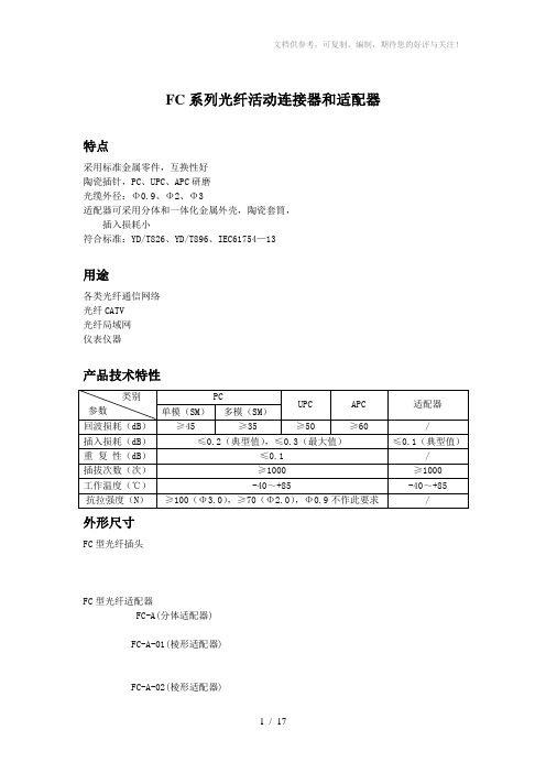
FC系列光纤活动连接器和适配器特点采用标准金属零件,互换性好陶瓷插针,PC、UPC、APC研磨光缆外径:Φ0.9、Φ2、Φ3适配器可采用分体和一体化金属外壳,陶瓷套筒,插入损耗小符合标准:YD/T826、YD/T896、IEC61754—13用途各类光纤通信网络光纤CATV光纤局域网仪表仪器产品技术特性外形尺寸FC型光纤插头FC型光纤适配器FC-A(分体适配器)FC-A-01(棱形适配器)FC-A-02(棱形适配器)FC-A-03(一体化薄形适配器)FC-A-04(厚板型形适配器)FC-A(H) (H型适配器)FC-A(H)-02 (小H型适配器)FC-A(D) (D型适配器)SC/DSC系列光纤活动连接器和适配器特点推拉式结构,轴向锁紧,连接快速、可靠标准塑料壳体,互换性好陶瓷插针,PC、UPC、APC研磨陶瓷套筒,插入损耗低光缆外径:Φ0.9、Φ2.0、Φ3.0单/双工连接器和适配器符合标准:YD/T895、IEC61754—4、IEC874—14、IEC874—1用途各类光纤通信网络光纤CATV光纤局域网产品技术特性外形尺寸SC型光纤插头DSC型光纤插头SC型光纤适配器 DSC型光纤适配器LC/DLC系列光纤活动连接器和适配器特点体积小(仅为SC的50%),重量轻,适合高密度安装标准塑料壳体,互换性好RJ-45推拉式锁紧结构,连接取卸快速、可靠单/双工连接器和适配器Φ1.25陶瓷插针,PC、UPC研磨光缆外径:Φ0.9、Φ2.0、Φ3.0符合标准:IEC61754—20、YD/T1272.1用途各类光纤通信网络新型同步终端设备和用户线路终端光纤到户、光纤到桌面DWDM系统ODF架产品技术特性外形尺寸LC型光纤插头DLC型光纤插头LC型光纤适配器 DLC型光纤适配器MU系列光纤活动连接器和适配器特点体积小(仅为SC的40%),重量轻,适合高密度安装标准塑料壳体,互换性好推拉式结构,轴向锁紧,连接快速、可靠Φ1.25陶瓷插针,PC、UPC研磨光缆外径:Φ0.9、Φ2.0符合标准:IEC61754—6、YD/T1200用途各类光纤通信网络光纤到户、光纤到桌面新型同步终端设备和用户线路终端DWDM系统ODF架产品技术特性外形尺寸MU型光纤插头 MU型光纤适配器ST系列光纤活动连接器及适配器特点标准金属零件,互换性好卡口式锁紧结构,连接快速、可靠陶瓷插针,PC和UPC研磨光缆外径:Φ0.9、Φ2.0、Φ3.0适配器采用一体化金属外壳陶瓷套筒,插入损耗低符合标准:YD/T987、IEC61754—2、IEC874—10用途各类光纤通信网络光纤局域网仪器仪表产品技术特性外形尺寸ST型光纤插头ST型光纤适配器MTRJ系列光纤活动连接器及适配器特点标准塑料壳体,互换性好RJ-45推拉式锁紧结构,连接取卸快速、可靠可同时接通2、4芯光纤,适合高密度安装光缆外径:Φ3集束缆、Φ3带状缆、Φ2并行缆、Φ0.9光纤符合标准:IEC61754—18、YD/T1272.2、TIA/EIA—604—12用途数据和通信系统光纤接入网光纤到户、光纤到桌面集成光电系统产品技术特性外形尺寸MTRJ型光纤插头(不带导针)MTRJ型光纤插头(带导针)MTRJ型光纤适配器DIN系列光纤活动连接器及转换器特点标准金属零件,互换性好陶瓷插针,PC、UPC研磨光缆外径:Φ0.9、Φ2.0、Φ3.0符合标准:IEC874-6用途各种光纤通信网络CATV光纤局域网仪器仪表产品技术特性外形尺寸DIN型光纤插头DIN型光纤适配器E2000系列光纤活动连接器和适配器E2000型系列光纤连接器是一种装有弹簧闸门的光纤连接器。
- 1、下载文档前请自行甄别文档内容的完整性,平台不提供额外的编辑、内容补充、找答案等附加服务。
- 2、"仅部分预览"的文档,不可在线预览部分如存在完整性等问题,可反馈申请退款(可完整预览的文档不适用该条件!)。
- 3、如文档侵犯您的权益,请联系客服反馈,我们会尽快为您处理(人工客服工作时间:9:00-18:30)。
目录
1.应用范围‥‥‥‥‥‥‥‥‥‥‥‥‥‥‥‥‥‥‥‥‥‥1
系列跳线‥‥‥‥‥‥‥‥‥‥‥‥‥‥‥‥‥‥‥‥1
材质‥‥‥‥‥‥‥‥‥‥‥‥‥‥‥‥‥‥‥‥‥‥‥1
规格、尺寸‥‥‥‥‥‥‥‥‥‥‥‥‥‥‥‥‥‥‥‥1
性能指标‥‥‥‥‥‥‥‥‥‥‥‥‥‥‥‥‥‥‥‥‥9
实验内容‥‥‥‥‥‥‥‥‥‥‥‥‥‥‥‥‥‥‥‥‥10
产品图片‥‥‥‥‥‥‥‥‥‥‥‥‥‥‥‥‥‥‥‥‥12
一体式适配器‥‥‥‥‥‥‥‥‥‥‥‥‥‥‥‥‥‥12
材质‥‥‥‥‥‥‥‥‥‥‥‥‥‥‥‥‥‥‥‥‥‥‥12
规格、尺寸‥‥‥‥‥‥‥‥‥‥‥‥‥‥‥‥‥‥‥‥13
性能指标‥‥‥‥‥‥‥‥‥‥‥‥‥‥‥‥‥‥‥‥‥14
1.应用范围
本规格书适用于FC型光纤活动连接器(跳线、适配器)的生产、检验和使用
FC型光纤活动连接器是一种以单芯插头和适配器为基础组成的螺纹旋转式连接器,它的特点是光纤镶嵌在标称直径为的高精密插针圆柱体中,两插头用M8×的螺帽和适配器进行螺纹连接。
使用条件:
工作温度:-25℃——+70℃
贮运温度:-40℃——+85℃
相对湿度:不大于95%(+40℃时)
大气压力:70Kpa——106Kpa
系列跳线、尾纤
材质
金属件:弹簧、外螺、内框、止动环、喇叭口、压环、尾座
陶瓷件:插芯
塑料件:尾套、防尘帽
光缆:二氧化硅、芳族聚酸胺、聚氯乙烯
如需符合ROHS,需在评审单上注明。
外观
产品外观应平滑洁净,金属零件表面无毛刺、油污、伤痕、裂纹及锈蚀现象,塑料、橡胶零件表面应平整、光滑、颜色均匀、一致性好、无裂纹现象。
默认光纤/光缆外皮颜色:单模紧套光纤(φ)外皮采用白色,多模紧套光纤(φ)外皮采用白色,单模光缆(φ2和φ3)外皮采用黄色,多模光缆(φ2和φ3)外皮采用橙色,光纤/光缆表面应圆整光滑,光缆上所印字迹应清晰,不允许有拖墨、漏印、错印、重叠、少墨等不良现象。
规格、尺寸
连接头规格、尺寸
FC连接头散件采用细螺纹外框,橡胶尾套,PC为黑色,APC为绿色,使用内置式尾套。
如有特殊要求,需在评审单上注明。
FC/PC光纤连接头规格图
FC/PC光纤连接头尺寸
以上尺寸参照标准YD_T 2007
FC/APC光纤连接头规格图
FC/APC插针体类型
FC/APC光纤连接头尺寸
以上尺寸参照标准YD_T 2007
光缆规格尺寸
单芯光缆结构
单芯外护套直径尺寸:±
紧套层直径尺寸:±
涂覆层直径尺寸:250μm±15μm
双芯光缆结构双芯外护套直径尺寸:×±
紧套层直径尺寸:±
涂覆层直径尺寸:250μm±15μm
单芯光缆结构
单芯外护套直径尺寸:±
紧套层直径尺寸:±
涂覆层直径尺寸:250μm±15μm
双芯光缆结构双芯外护套直径尺寸:×±
紧套层直径尺寸:±
涂覆层直径尺寸:250μm±15μm
光纤结构
紧套层直径尺寸:±
涂覆层直径尺寸:250μm±15μm
跳线规格尺寸
长度L由客户定义
PVC材质L±或按客户要求
LSZH材质L±或按客户要求
FC型单芯跳线
FC型单芯跳线
FC型双芯跳线
FC型双芯跳线
FC型尾纤
单模、光缆颜色为黄色,的为白色,PVC材质。
多模、光缆颜色为橙色,的为白色,PVC材质。
APC型号、光缆颜色为黄色,的为白色,PVC材质。
如有其他材质及颜色等要求,需在评审单上注明。
性能指标
插入损耗
PC型单模插头的插入损耗应≤,PC型多模插头的插入损耗应≤
APC型插头的插入损耗应≤。
光纤转接器的插入损耗应≤。
注:单模产品的插入损耗应同时满足1310nm和1550nm波长要求
回波损耗
单模PC型插头的回波损耗应≥50dB,单模APC型插头的回波损耗应≥60dB。
插针端面结构如图1所示,插针端面几何尺寸要求见表1。
PC型插芯端面示意图APC型插芯端面示意图
图1
表1.端面几何尺寸指标:
伤和污染要求:
一级端面标准:
二级端面标准:
重复性和互换性
任意挑选的同型号光纤插头和同型号光纤转接器进行互换性试验,产品应能顺利地连接和脱离,且产品不得有任何机械损伤、插针表面无明显划痕。
重复性和互换性插入损耗性能:PC面的插入损耗应≤APC面的插入损耗应≤;PC面回波损耗≥50dB,APC面回波损耗≥60dB。
实验内容(如客户要求以下实验内容,需在评审单中注明):
低温实验
温度-40℃,温度变化速率不大于1℃/min,恒温持续时间96h,恢复时间1h。
不得有机械损伤,如变形、龟裂、松弛等现象。
高温实验
温度+80℃,温度变化速率不大于1℃/min,恒温持续时间96h,恢复时间1h。
不得有机械损伤,如变形、龟裂、松弛等现象。
湿热(稳态)
温度40℃,湿度90%~95%,温度变化速率不大于1℃/min,持续保持96h后,置于室温2h,擦净后测量其光学性能。
不得有机械损伤,如变形、龟裂、松弛等现象。
跌落
在1米的高度,让连接头自由跌落撞击表面,来回撞击5次,擦净后测量其光学性能。
不得有机械损伤,如变形、龟裂、松弛等现象。
高低温循环试验
低温温度-25℃,温度+70℃,温度变化速率不大于1℃/min,高低温个恒温持
续时间30min,循环5次,恢复时间1h。
不得有机械损伤,如变形、龟裂、松弛等现象。
重复性试验
在对方插头插入的情况下,以通常的方式将被测插头予以插入和拔出,共接续10次。
不得有机械损伤,插针表面无明显划痕
盐雾试验
盐雾浓度:5%;严酷度:+35℃,48h。
将试样在室温下测量其光学性能,然后将试样置于盐水喷雾箱内,加温到35℃后恒温48h,把试样取在室温放置2h,擦净后测量其光学性能。
不得有机械损伤,如变形、龟裂、松弛等现象
机械耐久性
在对方插头插入的状况下,以通常使用的方式予以插入和拔出,每10次记录一次光学性能数据,同时对试样进行清洁,共插拔500次。
不得有机械损伤,插针表面无明显划痕
拉力实验
将插头端面保护好并固定,自然下垂,以规定的速率50N/min<速率<250N/min
施加负荷,负荷量为50N,持续10min,取下试样后进行光学性能测量
不得有机械损伤,如变形、龟裂、松弛等现象
φ跳线或尾纤不进行拉力实验。
光缆热收缩实验
样品数7米,以80℃高温恒温4小时,光缆外护套收缩率<5%,光纤<1%各种试验后插入损耗及回波损耗变化量单位:dB
光纤连接器其他技术指标满足标准YD/T826、YD/T895、YD/T896产品图片
12芯FC/PC扁带尾纤
FC/PC-SC/APC跳线
一体式适配器
材质
金属件:主体、阻挡体
塑料件:防尘帽
陶瓷件:套管
以上如需符合ROHS,及经过盐雾试验与阻燃试验,需在评审单上注明。
外观
产品外观应平滑洁净,金属零件表面无毛刺、油污、伤痕、裂纹及锈蚀现象,塑料零件表面应平整、光滑、颜色均匀、一致性好、无裂纹现象。
FC/UPC-FC/UPC 适配器
规格、尺寸
适配器规格图
适配器尺寸
以上尺寸参照标准YD-T 2007性能指标。