排水器说明
自动防煤气泄漏排水器(水封)说明书
自动防煤气泄漏排水器(水封)说明书FPX型自动防煤气泄漏装置是我公司的专利产品(发明专利号:200610039622.0,实用新型专用号:200620072272.3),本产品作为架空敷设的煤气管道用排水器自动防煤气泄漏装置,安装于排水器溢流管侧,可有效地防止因煤气管网压力波动或其它原因引起的排水器有效水位异常降低造成的煤气泄漏,是一种安全环保型产品。
工作原理:当煤气压力正常时,浮筒阀上升,水平阀板由于重力自动下落,打开水平阀,可实现溢流排水功能。
当煤气排水器受到超压或其它原因造成脱水情况下,浮筒下落自动关闭水平阀,浮筒阀受煤气压力作用下,自动关闭。
同时带动水平阀杆上升,传感器输出信号报警,从而切断煤气泄漏途径。
标注示例:FPXmm煤气最低工作压力mmh2o 本产品设计独特,结构紧凑,自动化程度高,安装维护方便,使用寿命长,同时便于观察排水器密封水位,具有自动报警功能,因而提高了工作效率,减轻了劳动强度,尤其在异常时,能有效地遏止泄漏煤气造成的灾害。
本产品与排水器配套使用,使用时根据排水器水封高度,确定溢流口高度进而确定本产品安装高度。
正常工作时,排水器中充满水至溢流口溢水为止,此时可观察到防煤气泄漏装置指示杆伸出筒外于正常位置,如工作过程中报警器发出报警信号,应观察指示杆位置变化,当指示杆向下降落时,则表明排水器中水位已降落,应及时补水;当观察到指示杆向上顶起时,则表明管网内发生漏气现象应及时予以排除,待恢复到正常情况后,方可继续工作。
注:1)防煤气泄漏装置中密封垫属于易损件,材质采用硅橡胶,隔一段时间须检查维护,以保证系统的密封性。
2)电控箱中电源采用5号1.5V干电池9节,三个月左右须调换更新。
安装调试注意事项:在运输途中为便于固定(见附图),将锁紧帽与锁紧螺母松开,接近开关接触板与接近开关调整至正常位置,正常位置为筒体内加水至溢流口位置时指示导杆所处的位置。
此时接近开关接触板与接近开关之间间隙必须调至4mm之内。
电子排水器说明
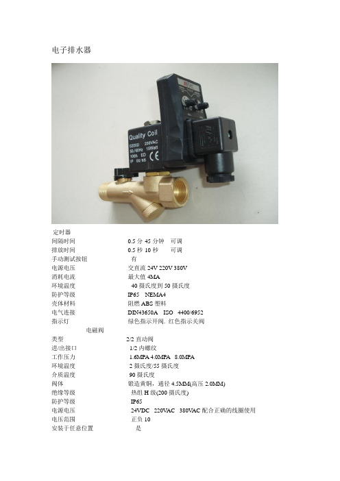
定时器间隔时间0.5分-45分钟可调排放时间0.5秒-10秒可调手动测试按钮有电源电压交直流24V-220V-380V消耗电流最大值4MA环境温度-40摄氏度到50摄氏度防护等级IP65 NEMA4壳体材料阻燃ABS塑料电气连接DIN43650A ISO 4400/6952指示灯绿色指示开阀. 红色指示关阀电磁阀类型2/2直动阀进/出接口1/2内螺纹工作压力 1.6MPA 4.0MPA 8.0MPA环境温度2摄氏度/55摄氏度介质温度90摄氏度阀体锻造黄铜,通径4.5MM(高压2.0MM)绝缘等级热组H级(200摄氏度)防护等级IP65电源电压24VDC 220V AC 380V AC配合正确的线圈使用电压范围正负10安装于任意位置是HAD20B兰色圆球形电子排水器.当水杯内无压力时,浮子因自重而下降。
压块关闭内腔孔,活塞被弹簧压下,而冷凝通过排水水杯内有压力时,当压力在1KG以上时,活塞克服弹簧力向上压,因而排水道关闭,水杯内部与外界隔断水杯内有冷凝水时,当冷凝水收集到一定程度时,浮子因浮力升起,打开内腔孔,压力进入内腔,活塞被压力和弹簧压下,冷凝水通过排水道管排水型号:HAD-20B最大工作压力:16PAR(kg/c㎡)最高工作温度:100℃(摄氏度)进液接口:1/2BSP出液接口:1/2BSP最大排放能力:400L/时HAD20B兰色圆球形电子排水器.当水杯内无压力时,浮子因自重而下降。
压块关闭内腔孔,活塞被弹簧压下,而冷凝通过排水水杯内有压力时,当压力在1KG以上时,活塞克服弹簧力向上压,因而排水道关闭,水杯内部与外界隔断水杯内有冷凝水时,当冷凝水收集到一定程度时,浮子因浮力升起,打开内腔孔,压力进入内腔,活塞被压力和弹簧压下,冷凝水通过排水道管排水。
排水器说明
排水器安装与使用说明及注意事项1.煤气排水器要安装在平整的地面基础上,底座可与设备基础预埋件通过地脚螺栓固定,设备基础要牢固,防止塌陷或倾斜。
2. 煤气排水器要垂直安装,不可倾斜,保证煤气排水器工作可靠。
3. 现场煤气管道与煤气排水器煤气进入管相连接,法兰连接处要使用密封垫,保证密封严密,煤气不外泄漏,煤气管道与排水器相连管道,需2个闸阀控制,确保使用及维修安全。
4. 煤气排水器冷凝水排水管要通入到附近的下水道中,不可将冷凝水直接排放到设备基础下。
5. 煤气排水器四周要有护栏和警示牌,防止发生碰撞泄漏等意外事故。
6. 煤气排水器使用前,必须对煤气排水器进行加水!加水时,要首先打开煤气排水器排气管帽,再利用煤气排水器上的加水口对煤气排水器进行加水,从低压腔(由系统管道进水管所在腔室)注入水,当煤气排水器外部的冷凝水排水管向外淌水时,煤气排水器加水完成。
加水完成后,必须将煤气排水器管帽密封好,防止煤气泄漏!7.定期通过观察孔检查排水器的水位,当排水器的水位下降至煤气压力将击穿排水器的水封时(排水器实体高度的2/3),排水器应进行给水处理,给水方法与首次注水方法相同。
(注:此时管帽内含有煤气,注意防护)8. 排水器选用电伴热的加热方式,要将电伴热接线盒与现场电源(380V)相连接,注意接线端子连接牢固,不能发生虚接。
现场电源线路要配有可靠的电源开关,电源开关盒安装在合适的位置上,便于冬季根据环境温度对排水器进行供电保温操作,初始状态上限值22℃,下限值16℃。
9. 用户可以根据煤气含尘情况和设备现场使用的实际情况,对煤气排水器进行排污和清理工作,建议每月清理一次。
煤气排水器排污时,必须首先彻底关闭煤气阀门,切断电源,杜绝明火,在通风良好的情况下进行。
排污后,必须对煤气排水器再加水!加水操作规程如上所述。
Wilkerson Corp M21系列自动排水器商品说明说明书
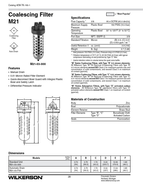
28Catalog 9EM-TK-190-1Pneumatic Division Richland, MichiganDimensionsM21-03-000Coalescing Filter M21SpecificationsFlow Capacity * 3/8 95.4 SCFM (45.0 dm3/s)Maximum Supply Plastic Bowl 150 PSIG (10.3 bar) Pressure Operating Plastic Bowl 32° to 125°F (0° to 52°C)Temperature Port SizeNPT / BSPP-G3/8Standard Filtration Micron (B) 0.5, (C) 0.01 (D) 0.003 ppm / wt **Useful Retention † oz. (cm3) 3.9 (116)Weightlb. (kg)3.7 (1.68)* Inlet pressure 150 PSIG (10.3 bar). Pressure drop of 3 PSID (0.2 bar).** Filtration temperature of 70°F (21°C) @100 PSIG (6.9 bar) with typical compressor lubricating oil and protected by Type “C” filter.†Useful retention refers to volume below the quiet zone baffle.“M” Series Coalescing Filters, with Type “B” 0.5 micron elements: All Wilkerson Type “M” Oil Removal (Coalescing) Filters with Type “B” 0.5 micron elements exceed ISO Class 2 for maximum particle size and concentration of solid contaminants, and exceed Class 3 on maximum oil content (ppm/wt).“M” Series Coalescing Filters, with Type “C” 0.01 micron elements: All Wilkerson T ype “M” Oil Removal (Coalescing) Filters with Type “C” 0.01 micron elements exceed ISO Class 1 for maximum particle size and concentration of solid contaminants, and exceed Class 1 on maximum oil content (ppm/wt).“M” Series Adsorption Filters, with Type “D” activated carbon elements: All Wilkerson Type “M” adsorption filters with Type “D” activated carbon elements exceed ISO Class 1 on maximum oil content (ppm/wt).Materials of ConstructionBody ZincBowlPolycarbonate Element RetainerBrass Stud Filter Elements Type “B”, “C” Borosilicate ClothType “D” Activated CarbonSealsFluorocarbonFeatures• Manual Drain• 0.01 Micron Rated Filter Element• Quick-disconnect Bowl Guard with Integral Plastic Bowl and Safety Latch • Differential Pressure IndicatorFilterAuto DrainCatalog 9EM-TK-190-129Pneumatic Division Richland, MichiganOrdering InformationReplacement Bowl KitsPlastic Bowl –Bowl Guard, Manual Drain ..................................FRP-95-722 Bowl Guard, Automatic Drain .............................MRP-95-722Replacement Element KitsType “B”, 0.5 Micron ...............................................MSP-95-990Type “C”, 0.01 Micron .............................................MTP-95-550Type “D”, Oil Vapor Removing ...............................MXP-95-537AccessoriesAutomatic Drain ......................................................GRP-95-973Cap, Differential Pressure Indicator – For pressures over 150 PSIG .............................GRP-95-020Differential Pressure Indicator ................................DP2-01-000Manual Flex-Tip .......................................................FRP-95-610Wall Mounting Bracket, U-bolt Pipe Clamp ...........GRP-95-734321040302010AIR FLOW RATEdm 3/s0.20.1P R E S S U R E D R O Pb a r54321102030405000.10.20.3b a rSCFM dm 3/sP R E S S U R E D R O PAIR FLOW RATEAIR FLOW RATEdm 3/sP R E S S U R ED R O P102030405000.10.2b a rCoalescing Filter M21。
BRP型罐区自动截油排水器说明书(小本)
一、引言GB50351-2005《储罐区防火堤设计规范》阐明自动截油排水设备的重要性:“目前许多储罐区场地的雨水排放设备极不完善…储罐区堤内雨水排放的问题是有关安全的一个重要方面,为彻底解决这个问题,杜绝因此而带来的安全隐患,在规范上必须提出严格的要求—储罐区必须设置安全可靠的截油排水设备、绝对避免油流的外泄。
”为响应石化行业油罐罐区排放洗仓水、雨水自动的安全化、自动化排放的需求,我公司研发了BRP型罐区自动截油排水器,它可全方面解决雨水及时、安全、自动化的排放问题,避免人工操作不及时的弊端,杜绝因泡油及相关高危事故的发生。
该设备原理独特、结构简单、性能卓越、安装使用维护简便,是理想的油罐罐区排水安环装置。
二、原理本产品根据油轻水重的特性,用平均密度略小于水的不锈钢外壳浮筒在油水介质中的浮力作为动力,当罐区沉砂井中有水和油两种介质时,油浮在上层,水在下层,水位在几乎淹没浮筒时,浮筒水的液压下上浮,通过连杆带动杠杆旋转,拉开除蹩阀,消除背压。
如水位再升高,浮筒将继续上浮,连带杠杠旋开排水阀,水流入出水筒内,超过排水管高度时,依靠水位差排出。
因为始终存在大约1000-1700毫米的水封段,所以该类设备又被称为“水封阀”或“水封器”。
当罐区出现突发性大量泄油事故时,沉砂井内的介质是油,浮筒重力大于浮力,通过杠杆将除蹩阀芯的通气孔闭合,进而将排水阀俩次性关闭严密,阻止油品外泄。
同时由于水封段的存在,所以油品不会进入排水管而被排出,这样就实现全自动截油排水。
能保证在垫片坏损情况下,油品大量泄漏,油位高度低于防火墙高度的工况下,24小时渗透步超过10升,所以本品本质非常安全。
为保证所排水的含油率极低,注意定期清除沉砂井水表面的油层。
三、优点不需任何能源实现自动控制,安全、环保、经济;水封段高,二次密封,确保罐区油品不外泄:产品采用二次密封阀的特殊设计结构,浮力先通过杠杆带拉开阀针,消除蹩压,杠杆继续移动,除蹩阀和排水阀阀门很灵活的一起开始排水,从而解决了除蹩阀与排水阀不同步的现象,克服了关闭不严的缺点,确保罐区安全;二、体积小、结构合理、不需补充水,安装、使用、维护极为简便,较同类产品更为卓越;三、水流到一定高度时,阀门完全开启、自动排水,能随液面变化,确保水流及时排出和泄油工况下完全关闭,有油水混合物时实行油留水走,全天候工作,避免了雨后开阀天晴关阀的麻烦,防止事故的发生。
排水器的工作原理
排水器的工作原理
排水器是一种常见的设备,用于排除排水系统中的废水和污垢。
它的工作原理主要分为以下几个步骤:
1. 捕捉:当废水通过排水管道流入排水器时,排水器底部的捕捉网会阻止固体颗粒进入下水道,以防止堵塞管道。
2. 隔离:排水器通常具有一个水封弯管,该弯管中的水封能够防止下水道中的恶臭气体逆流进入室内,同时还能减少声音传递。
3. 过滤:排水器的捕捉网能够过滤掉细小的颗粒物,如头发、食物残渣等,防止它们进入下水道造成堵塞。
4. 排水:废水经过过滤后,会通过排水器的出水口进入下水道,从而实现废水的排放。
5. 清洁:由于排水器经常接触到污垢和杂物,定期对排水器进行清洁是必要的,以保持其正常工作状态。
综上所述,排水器通过捕捉、隔离、过滤、排水和清洁等步骤,能够有效地将废水排除,并防止固体颗粒进入下水道,以维持排水系统的正常运行。
蒸汽泵自动排水器说明书

Note 1) Drain guide is NPT1/8 (applicable to the AFM20-A, AFD20-A) and NPT1/4 (applicable to the AFM30-A/40-A, AFD30-A/40-A). The auto drain port comes with ø3/8" One-touch fitting (applicable to the AFM30-A/40-A, AFD30-A/40-A).Note 2) Drain guide is G1/8 (applicable to the AFM20-A, AFD20-A) and G1/4 (applicable to the AFM30-A/40-A, AFD30-A/40-A).Note 3) A bracket is not assembled and supplied loose at the time of shipment. Including 2 mounting screwsNote 4) When pressure is not applied, condensate which does not start the auto drain mechanism will be left in the bowl. Releasing the residual condensate beforeending operations for the day is recommended.Note 5) If the compressor is small (0.75 kW, discharge flow is less than 100 L/min[ANR]), air leakage from the drain cock may occur during start of operations. N.C.type is recommended.Note 6) Refer to Chemical data on page 40 for chemical resistance of the bowl.Note 7) Standard material (polycarbonate)Note 8) Without a valve function.Note 9) For thread type: NPT. This product is for overseas use only according to the new Measurement Law. (The SI unit type is provided for use in Japan.)Note 10) : For thread type: NPT onlyMist SeparatorAFM20-A to AFM40-AMicro Mist SeparatorAFD20-A to AFD40-A• Series AFM Nominal filtration rating: 0.3 µm • Series AFD Nominal filtration rating: 0.01 µmAFM AFD • Option/Semi-standard: Select one each for a to f .• Option/Semi-standard symbol: When more than one specification is required, indicate in alphanumeric order.Example) AFM30-03BD-CR-AAFD20-A AFM20-A AFD40-AAFM40-AJIS SymbolMist Separator Micro Mist Separator———— ——— — —Note 7)—Note 7)—— — —Note 10)Note 10)Note 10)21L21LHow to Order37C o u r t e s y o f C M A /F l o d y n e /H y d r a d y n e ▪ M o t i o n C o n t r o l ▪ H y d r a u l i c ▪ P n e u m a t i c ▪ E l e c t r i c a l ▪ M e c h a n i c a l ▪ (800) 426-5480 ▪ w w w .c m a f h .c o mlubricant to the outlet side.Note 2) When the compressor oil mist discharge concentration is 30 mg/m 3 (ANR).Note 3) Bowl O-ring and other O-rings are slightly lubricated.Note 2) Minimum operating pressure: N.O. type–0.1 MPa; N.C. type–0.1 MPa (AD27-A) and 0.15 MPa (AD37-A/47-A),Please consult with SMC separately for psi and °F unit display specifications.Note 3) Please consult with SMC for details on drain piping to fit NPT or G port sizes.Note 4) The bowl assembly includes the bowl O-ring.38Mist Separator SeriesAFM20-A to AFM40-AMicro Mist Separator Series AFD20-A to AFD40-AA CA F A R A L A W A L A F A R A F A F M A R A W A F M A F A F M / A F DA R A L A W A t t a c h m e n t C o u r t e s y o f C M A /F l o d y n e /H y d r a d y n e ▪ M o t i o n C o n t r o l ▪ H y d r a u l i c ▪ P n e u m a t i c ▪ E l e c t r i c a l ▪ M e c h a n i c a l ▪ (800) 426-5480 ▪ w w w .c m a f h .c o m501001502000Flow rate L/min (ANR)P 1=0.3MP a P 1=0.5M P a P 1=0.7M Pa P 1=0.3M P a P 1=0.5M P a P 1=0.7M P a 501000Flow rate L/min (ANR)P1=.3M P a P1=0.5MP aP 1=0.7M P aP 1=.3MP aP 1=0.5M P aP 1=0.7M P a 100200300500400600AFM30-AFlow rate L/min (ANR)P1=0.3M P a P 1=.5M P a P 1=0.7M Pa P 1=0.3M P a P 1=0.5M P a P1=0.7M P a AFD30-A501001502000Flow rate L/min (ANR)P 1=0.3M P aP 1=0.5M P aP 1=0.7M P aP 1=0.3M P aP 1=0.5M P aP 1=0.7M P a20080010004006000AFM40-AFlow rate L/min (ANR)P 1=0.3M P aP 1=0.5M P aP 1=0.7MP a P1=0.3M P aP1=0.5M P aP 1=0.7M P a1002003005004006000AFD40-AFlow rate L/min (ANR)P1=0.3MP aP 1=0.5M P a P 1=0.7MP aP 1=0.3MP a P 1=0.5MP aP 1=0.7M P a Flow Characteristics (Representative values)When saturated with oil Initial state39Series AFM20-A to AFM40-A Series AFD20-A to AFD40-AC o u r t e s y o f C M A /F l o d y n e /H y d r a d y n e ▪ M o t i o n C o n t r o l ▪ H y d r a u l i c ▪ P n e u m a t i c ▪ E l e c t r i c a l ▪ M e c h a n i c a l ▪ (800) 426-5480 ▪ w w w .c m a f h .c o mAir Supply1. Install an air filter (Series AF) as a pre-filter on the inlet side of the mist separator to prevent premature clog-ging.2. Install a mist separator (Series AFM) as a pre-filter on the inlet side of the micro mist separator to prevent pre-mature clogging.3. Do not install on the inlet side of the dryer as this can cause premature clogging of the element.CautionMaintenance1. Replace the element every 2 years or when the pres-sure drop becomes 0.1 MPa, whichever comes first, to prevent damage to the element.WarningDesign1. Design the system so that the mist separator is installed in a pulsation-free location. The difference between in-ternal and external pressure inside the element should be kept within 0.1 MPa, as exceeding this value could cause damage.CautionSelection1. Do not allow air flow that exceeds the rated flow. If the air flow is allowed outside the range of the rated flow even momentarily, drainage and lubricant may splash at the outlet side or cause damage to the component.2. Do not use in a low pressure application (such as a blower). F.R.L. unit has its own minimum operating pressure depending on the equipment and is designed specifically to function with compressed air. If used be-low the minimum operating pressure, a loss of perfor-mance and malfunction can occur. Please contact SMC if an application under such conditions cannot be avoid-ed.Caution1. When the bowl is installed on themist separator, or micro mist sepa-rator, install them so that the lock button lines up to the groove of the front (or the back) of the body to avoid drop or damage of the bowl.Warning Design / Selection 1. The standard bowl for the air filter, filter regulator, and lubricator, as well as the sight dome for the lubricator and bowl guard are made of polycarbon-ate. Do not use in an environment where they are exposed to or come in contact with organic sol-vents, chemicals, cutting oil, synthetic oil, alkali, and thread lock solutions.Effects of atmosphere of organic solvents and chemicals, and where these elements are likely to adhere to the equipment.Mist Separator SeriesAFM20-A to AFM40-AMicro Mist Separator Series AFD20-A to AFD40-ABe sure to read before handling. Refer to back cover for Safety Instructions, “Handling Precautions for SMC Products” (M-E03-3) and the Operation Manual for F.R.L. Precautions. Please download it via our website, 40A CA F A R A LA W A LA F A R A F A F M A R A W A F M A FA F M / A F DA RA L A WA t t a c h m e n tC o u r t e s y o f C M A /F l o d y n e /H y d r a d y n e ▪ M o t i o n C o n t r o l ▪ H y d r a u l i c ▪ P n e u m a t i c ▪ E l e c t r i c a l ▪ M e c h a n i c a l ▪ (800) 426-5480 ▪ w w w .c m a f h .c o mINFloat type auto drain (N.C.)Float type auto drainN.O.AFM30-A to AFM40-06-A AFD30-A to AFD40-06-AAFM20-A AFD20-AConstruction41Series AFM20-A to AFM40-A Series AFD20-A to AFD40-AC o u r t e s y o f C M A /F l o d y n e /H y d r a d y n e ▪ M o t i o n C o n t r o l ▪ H y d r a u l i c ▪ P n e u m a t i c ▪ E l e c t r i c a l ▪ M e c h a n i c a l ▪ (800) 426-5480 ▪ w w w .c m a f h .c o mAFM20-A AFD20-AAFM30-A to AFM40-06-A AFD30-A to AFD40-06-ADimensions42Mist Separator SeriesAFM20-A to AFM40-AMicro Mist Separator Series AFD20-A to AFD40-AA CA F A R A L A W A L A F A R A F A F M A RA W A F M A F A F M / A F DA RA L A W A t t a c h m e n t C o u r t e s y o f C M A /F l o d y n e /H y d r a d y n e ▪ M o t i o n C o n t r o l ▪ H y d r a u l i c ▪ P n e u m a t i c ▪ E l e c t r i c a l ▪ M e c h a n i c a l ▪ (800) 426-5480 ▪ w w w .c m a f h .c o m。
HAD-20型自动排水器说明
自动排水器资料
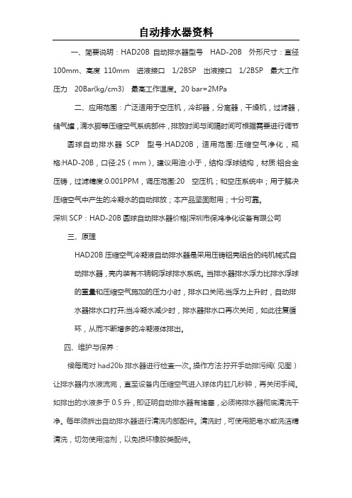
一、简要说明:HAD20B自动排水器型号HAD-20B外形尺寸:直径100mm、高度110mm进液接口1/2BSP出液接口1/2BSP最大工作压力20Bar(kg/cm3)最高工作温度。
20 bar=2MPa
二、应用范围:广泛适用于空压机,冷却器,分离器,干燥机,过滤器,储气罐,滴水脚等压缩空气系统部件,排放时间与间隔时间可根据需要进行调节圆球自动排水器SCP型号:HAD20B,适用范围:压缩空气净化,规格:HAD-20B,口径:25(mm),建议用油:小于,结构:浮球结构,材质:铝合金压铸,过滤精度:0.001PPM,调压范围:20空压机;和空压系统中;用于解决压缩空气中产生的冷凝水的自动排放;本产品坚固耐用;十分可靠。
深圳SCP:HAD-20B圆球自动排水器价格|深圳市保鸿净化设备有限公司
三、原理
HAD20B压缩空气冷凝液自动排水器是采用压铸铝壳组合的纯机械式自动
排水器,壳内装有不锈钢浮球排水系统。
当排水器排水浮力比排水浮球的
重量和压缩空气施加的压力小时,排水口关闭;当浮力上升时,自动排水
器排水口打开;当冷凝水减少时,排水器排水口再次关闭,如此往复循环,
从而不断增多的冷凝液体排出。
四、维护与保养:
候每周对had20b排水器进行检查一次。
操作方法:拧开手动排污阀(见图)让排水器内水液流完,直至设备内压缩空气进入球体内缸几秒钟,再关闭手阀。
如排出的水液多于0.5升,即证明自动排水器有堵塞,必须将排水器彻底清洗干净。
每年须拆出自动排水器进行清洗内部配件。
清洗时,可使用肥皂水或洗洁精清洗,切勿使用溶剂,以免损坏橡胶类配件。
2014年5月13日。
- 1、下载文档前请自行甄别文档内容的完整性,平台不提供额外的编辑、内容补充、找答案等附加服务。
- 2、"仅部分预览"的文档,不可在线预览部分如存在完整性等问题,可反馈申请退款(可完整预览的文档不适用该条件!)。
- 3、如文档侵犯您的权益,请联系客服反馈,我们会尽快为您处理(人工客服工作时间:9:00-18:30)。
排水器安装与使用说明及注意事项
1.煤气排水器要安装在平整的地面基础上,底座可与设备基础预埋件通过地脚螺栓固定,设备基础要牢固,防止塌陷或倾斜。
2. 煤气排水器要垂直安装,不可倾斜,保证煤气排水器工作可靠。
3. 现场煤气管道与煤气排水器煤气进入管相连接,法兰连接处要使用密封垫,保证密封严密,煤气不外泄漏,煤气管道与排水器相连管道,需2个闸阀控制,确保使用及维修安全。
4. 煤气排水器冷凝水排水管要通入到附近的下水道中,不可将冷凝水直接排放到设备基础下。
5. 煤气排水器四周要有护栏和警示牌,防止发生碰撞泄漏等意外事故。
6. 煤气排水器使用前,必须对煤气排水器进行加水!加水时,要首先打开煤气排水器排气管帽,再利用煤气排水器上的加水口对煤气排水器进行加水,从低压腔(由系统管道进水管所在腔室)注入水,当煤气排水器外部的冷凝水排水管向外淌水时,煤气排水器加水完成。
加水完成后,必须将煤气排水器管帽密封好,防止煤气泄漏!
7.定期通过观察孔检查排水器的水位,当排水器的水位下降至煤气压力将击穿排水器的水封时(排水器实体高度的2/3),排水器应进行给水处理,给水方法与首次注水方法相同。
(注:此时管帽内含有煤气,注意防护)
8. 排水器选用电伴热的加热方式,要将电伴热接线盒与现场电源(380V)相连接,注意接线端子连接牢固,不能发生虚接。
现场电源线路要配有可靠的电源开关,电源开关盒安装在合适的位置上,便于冬季根据环境温度对排水器进行供电保温操作,初始状态上限值22℃,下限值16℃。
9. 用户可以根据煤气含尘情况和设备现场使用的实际情况,对煤气排水器进行排污和清理工作,建议每月清理一次。
煤气排水器排污时,必须首先彻底关闭煤气阀门,切断电源,杜绝明火,在通风良好的情况下进行。
排污后,必须对煤气排水器再加水!加水操作规程如上所述。