亚安产品手册
亚安网络监控系统软件使用手册

4.2.1 菜单栏 ................................................................................................................ 11 4.2.2 顶部工具栏......................................................................................................... 11 4.2.3 视频显示区.........................................................................................................12 4.2.4 右部工具栏.........................................................................................................12 4.2.5 底部工具栏.........................................................................................................12
AZM 161 B ST1_AS A 安全设备手册说明书

25.10.2016 10:34:26hDatasheet AZM 161 B ST1AS A AZM 161 B ST1AS AAS interface safety at work / Safety switchgear / Solenoid interlock / AZM 161ASPreferred typ(Minor differences between the printed image and the original product may exist!)• Solenoid interlock• Thermoplastic enclosure • High holding force 2000 N • 130 mm x 90 mm x 30 mm• Interlock with protection against incorrect locking.• Doubleinsulated • Long life• Integrated ASInterface• Solenoid supply aus AS interface • Actuator monitored • Manual releaseOrdering detailsProduct type description AZM 161 B ST1AS A Article number 101209091EAN code 4030661396446eCl@ss 27272603ApprovalApprovalASiTÜV USA/CANClassificationStandards EN ISO 138491, IEC 61508PLup c Control category 1PFH 1.14 x 10⁶ / h notice up to max. 100.000 switching cycles/year SIL up 1Mission time20 Y earsIf a fault exclusion for hazardous damage of the 1channel mechanics is authorized and an adequate protection against tampering is ensured, suitable for use up to:Standards EN ISO 138491, IEC 61508PLup d Control category 3PFH value 1.01 x 10⁷ / h notice up to max. 100.000 switching cycles/year SIL up 2Mission time20 Y earsGlobal PropertiesProduct name AZM 161 ASStandards EN 50295, EN 6094751, IEC 61508, EN ISO 138491 Compliance with the Directives (Y/N) Y esNumber of actuating directions3 pieceActive principle electromechanicalDuty cycle Magnet 100 %Materials Material of the housings Plastic, glassfibre reinforced thermoplastic, selfextinguishingHousing coating NoneWeight450 gGuard locking monitored (Y/N)NoActuator monitored (Y/N)Y esResponse time< 100 msMechanical dataActuating play in direction of actuation 5.5 mmDesign of electrical connection connector plug M12, 4poleconnector rightMechanical life> 1.000.000 operationsrestistance to shock30 g / 11 msResistance to vibration10 Hz ... 150 Hz, Amplitude 0,35 mmEmergency unlocking device (Y/N)NoManual release (Y/N)Y esEmergency release (Y/N)NoLatching force5 NClamping force F2000 NMax. Actuating speed2 m/sActuating frequency max. 1000 / hAmbient conditionsAmbient temperature Min. environmental temperature−25 °C Max. environmental temperature+60 °CStorage and transport temperature Min. Storage and transport temperature−25 °C Max. Storage and transport temperature+85 °CRelative humidity30 % ... 95 % noncondensingProtection class IP67 to IEC/EN 60529Protection rating IIAir clearances and creepage distances To IEC/EN 606641 Rated impulse withstand voltage U imp0,8 kV Rated insulation voltage U i32 VDC Overvoltage category III Degree of pollution3Electrical dataPower to unlock NoPower to lock Y esElectrical data AS interfaceASi Supply voltage26.5 ... 31.6 VDC, Protection against polarity reversalASi operating current≤ 250 mAASi Device insulation internally shortcircuit proofASi Specification version V 2.1 Profile S7.B.F.E IOCode0x7 IDCode0xB IDCode10xF IDCode20xEASi Inputs Channel 1Data bits DI 0/DI 1= dynamic code transmission Channel 2Data bits DI 2/DI 3= dynamic code transmissionASi Outputs DO 0Solenoid control DO 1not used DO 2not used DO 3not usedASi Parameter bits P0Actuator detected P1Solenoid interlock locked P2magnet voltage in tolerance range P3error message locking/unlocking of the solenoid interlockblockedASi input module address0 Default on address 0, programmable via the ASInterface Master or Handheld programming deviceLED switching conditions displayLED switching conditions display (Y/N)Y esASi LED switching conditions display(1) yellow LED Channel 2 / ASi SaW Bit 2,3(2) green/red LED (ASi duo LED)Supply voltage / Communication error / slave address = 0or periphery error(3) yellow LED Channel 1 / ASi SaW Bit 0,1ATEXExplosion protection categories for gases NoneExplosion protected category for dusts NoneMiscellaneous dataApplicationssliding safety guard,removable guard,hinged safety guardDimensionsDimensions of the sensor Width of sensor130 mm Height of sensor90 mm Length of sensor30 mmPin assignment1ASi +2Aux − (P)3ASi −4Aux + (P)noticeInterlocks with power to lock principle may only be used in special cases after a thorough evaluation of the accident risk, since the guarding device can immediately be opened on failure of the electrical power supply or when the main switch is opened.Manual release• For maintenance, installation, etc.• For manual release using M5 triangular key, available as accessoryIncluded in deliveryActuators must be ordered separately.Ordering codeAZM 161 (1) (2)AS (3)(4)(5)(6)(1)Z Guard lockingmonitoredB Actuator monitoredBZ(2)ST1Connector bottomST2Connector right(3)without Latching force 5 NR Latching force 30 N(4)without Power to unlockA Power to lock(5)without Solenoid supply ausAS interfaceP Solenoid supply aus24 VDC (Aux)(6)without Manual releaseN Emergency releaseT Emergency exitDocumentsOperating instructions and Declaration of conformity (en) 569 kB, 12.03.2010Code: mrl_azm161as_enOperating instructions and Declaration of conformity (it) 493 kB, 15.03.2010Code: mrl_azm161as_itOperating instructions and Declaration of conformity (es) 495 kB, 16.03.2010Code: mrl_azm161as_esOperating instructions and Declaration of conformity (pl) 319 kB, 11.02.2015Code: mrl_azm161as_plOperating instructions and Declaration of conformity (de) 572 kB, 12.03.2010Code: mrl_azm161as_deOperating instructions and Declaration of conformity (fr) 485 kB, 15.03.2010Code: mrl_azm161as_frOperating instructions and Declaration of conformity (jp) 712 kB, 14.11.2011Code: mrl_azm161as_jpOperating instructions and Declaration of conformity (nl) 478 kB, 15.03.2010Code: mrl_azm161as_nlBGtest certificate (de, en) 286 kB, 01.06.2010Code: z_161p01ImagesDimensional drawing (basic component)Contact arrangementOperating principleSystem componentsActuator101145117 AZM 161B1101144416 AZM 161B1E101171859 AZM 161B1ES101175431 AZM 161B1F101171125 AZM 161B1S101173089 AZM 161B12053 WITH BALL LATCH101164100 AZM 161B11747 WITH MAGNETIC LATCH101178199 AZM 161B12024101176642 AZM 161B12177 WITH CENTERING GUIDE101174113 AZM 161B62177 WITH CENTERINGGUIDE• For very smal actuating radii101170375 AZM 161B6S101144420 AZM 161B6• For very smal actuating radiiDoorhandle systemAZM 161STS30• Latching handle• Suitable for all types of guard• einsetzbar in Verbindung mit EXAZM 161suitable in combination with #01#Accessories101100887 TRIANGULAR KEY TKM5• For manual release using M5 triangular key, available asaccessory• For maintenance, installation, etc.K.A. Schmersal GmbH & Co. KG, Möddinghofe 30, D42279 WuppertalThe data and values have been checked throroughly. Technical modifications and errors excepted.Generiert am 25.10.2016 10:34:26h Kasbase 3.2.5.F.64I。
亚安云台说明书

-
第一部分 云台介绍
◆ 云台技术指标
一、 云台产品特性 1、 造型新颖,专利设计的走线方式节省了出线长度,保证了出线安全,使出线不会被破坏、磨损。 2、 云台选用永久型重载磁同步电机,具有云台停机保护功能,抗强风,运行平稳可靠。 3、 装有高性能长寿命进口组件变速箱,可加装双侧红外射灯(见图 1)。 4、 通讯协议转换功能:YAAN、Pelco-D、Pelco-P、AD、AB、行协、三星及多种波特率通讯。 5、 最多可设置 50 个预置位(YD 系列无预置位),配合 Computar 镜头,可以实现镜头的预置。 6、 YP 系列使用行业协议时,最多可以设置 5 条线扫路线,编辑 8 条巡航路线;YD 系列仅一条线扫路线, 且线扫边界不可设置靠限位开关控制其左右边界。 7、专 业 设 计 的 外 壳 便 于 拆 卸 、 安 装 、 维 修 。 8、铝合金材料耐高温、耐老化、抗腐蚀、防水、防酸雨。 9、H 型内置自动加热系统,适用于高寒冷地区。
协议 行业协议 V0.0
YAAN Pelco P Pelco D AD /AB
三星 Inter 行业协议 V1.0
1 OFF ON OFF ON OFF OFF ON 地址 9
2 OFF OFF ON ON OFF ON ON 地址 10
3 OFF OFF OFF OFF ON ON ON 地址 11
注意事项…………………………………..……………...1
第一部分 云台的介绍…………………………………... ………….2
云台产品特性………………………..…. ………………2
ID 设置……………………………..…………………….3
功能拨码开关设置…………...………………………….5
YS亚安一体化3040 YS3041(0827)
5.2
………………….….………..………….……………………………………6
5.3
........................................................................................................................ 7
最大预置速度 60°/s
通讯方式
RS485/ RS422
通讯协议
行业 V0.0,YAAN,Pelco-P,Pelco-D
通讯波特率
2400/4800/9600/19200 bps
预置位
最多可设置 80 个
自动扫描
行业 V0.0 协议时 5 条,其他协议时 1 条
可适配索尼系列摄像机:
①由直流 12V 电压给摄像机供电,镜头
3.2 自动扫描 变速云台在两个固定点或两个设定点之间按一定速度变速云台水平往返运动的过程. 注:预先设置左限位(视角边界)和右限位(视角边界),可实现云 台在左右限位区间内 往复巡视,巡视速度可采用编程方式先行设定.
3.3 自动巡航 变速云台按照一定顺序、一定时间间隔循环调用预置位的过程. 注:自动巡航功能是指可通过预先编程,将某些预置位按要求 的顺序编排到自动巡航的队 列中,只需一个命令就可让变速云台自动地按设定的预置位 顺序,并以设定的时间间隔往 复不停地运动.通过在各个重要位置设置预置位,可以实现变 速云台在预置位间的自动巡 航.
5
.......................................................................................................................................... 6
亚安产品手册
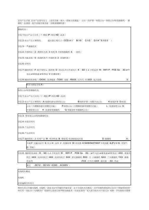
亚安产品手册亚安产品型号定义(适用范围:镜头、控制主机键盘、云台、防护罩、球型云台、球型云台/球型摄像机、摄像机、监视器、数字录像存储设备、音频视频解码器)模块化综合传输光端机光端机,就是光信号传输的终端设备。
由于目前技术的提高,光纤价格的降低使它在各个领域得到很好的应用,因此各个光端机的厂家就好比是雨后春笋般发展起来。
但是这里的厂家大部分技术并不是完全成熟,开发新技术需要耗资和人力、物力等,这就产生厂家多是中小企业,各品牌也先后岀现。
但是质量上还是差不多的,国外的光端机好但是价格昂贵,因此,国内厂家把生产光端机转型岀路了,用来满足国内的需要。
园区视频监控方案展开光端机简介概念工作原理光端机的常用术语光端机分类PDH光端机SDH光端机SPDH光端机通常所说的光端机概述1、模拟光端机2、数字光端机光端机从模拟走向数字光端机的传输距离光端机接口类型光端机品牌常见故障及解决方法一、没有视频信号二、画面出现干扰雪花常见故障解决之道视频光端机的选型视频光端机网管介绍主要特点如下光端机的特性:传输系统原理园区视频监控方案展开10MHz,音频带宽为40Hz〜20KHZ,体现了较强的动态范围宽度。
信噪比信噪比(SNR:Signal To Noise Ratio )是指光端机音源产生最大不失真声音信号强度与同时发岀的噪音强度之间的比率,通常以S/N表示,一般用分贝(dB)为单位。
信噪比越高表示音频质量越好,一般音频光端机的信噪比应该在60dB以上。
误码率误码率(BER : Bit Error Ratio )是衡量数据在规定时间内数据传输精确性的指标。
误码率=传输中的误码/所传输的总码数*100%。
如果有误码就有误码率。
信号电平信号电平(signal level )是指设备输岀信号和输入信号的功率比然后取对数值,通常用P表示,P=lgP2/P1。
信号阻抗信号阻抗(Signal Inpedanee )是指输入信号的电压与电流的比值,单位通常是Q (欧姆)。
亚安云台新产品介绍

2.7°/s恒速(可改造 0.3°/s~2.7°/s) 耐腐蚀铝合金及不锈钢 ----风速60m/s(216公里/时) 100VAC +/- 10% -10°C~+50°C
-50°C~+65°C 是
-45°C~+60°C 否
可改造低温达-30°C 否
四、高清摄像机专用云台
19
高清摄像机专用云台
百万像素网络)全双工通信可实 现角度等现场参数回传
手动水平旋转最低速度 0. 1°/S
LED阵列式红外灯\ 激光灯\热成像仪
可见光摄像机
RS-485远程升级
YS3051
13
室外中载变速云台——差异对照表 室外中载变速云台——差异对照表
亚安YS3051 亚安 15Kg 承载 可配4823(顶载) 4018(侧载) 用户可自由选配摄像 机镜头 最大可承受风速210 公里/时 -75°~+40° (顶载) 垂直旋转范围 +/-90° (侧载) 手动最低速度 手动最高速度 预置位速度 水平) (水平) 预置位精度 环境温度 可扩展夜视
亚安云台新品介绍
1
一、经济型夜视车载云台摄像机 经济型夜视
2
经济型夜视 经济型夜视车载云台摄像机
亚安球形云台用户说明书Y5X1X
司联系。
12 如遇下列情况请立即与本公司联系:
a.电源.控制线破损 b.使用错误的电源种类或电压 c.如掉落或机壳受损 d.产品在性能上出现异常 e.如按用户手册操作后仍未正常工作
13 更换零件时,请使用本公司认可的或与原部件性能相同的零件,未经认可的代用品可能会导致危险。
§ 1.2 注意事项
1 不要将任何物品放在产品内,这可能导致致命的短路。 2 避免产品承受强烈冲击或震荡。 3 产品运行时,不要触摸产品机体和表面。 4 避免将产品安装在有易燃,易爆或腐蚀性气体存在的场所。 5 不要将云台瞄准强光物体,否则可能导致 CCD 的损坏。 6 不可将室内云台安装在室外环境。 7 测试过程中云台内摄像机供电 DC12V 线缆不能短路。 8 为使球机正常工作(加热时),电源容量应符合技术指标中推荐的功率数值。 9 应使用屏蔽双绞线连接 RS-485 端口,屏蔽层应切实连接到信号 GND,如不连接信号 GND 可能会干扰通讯正常
附录.............................................................22
Y5X1X 系列球型云台用户手册
YN
第一章 安全注意事项
Y5X1X 系列球型云台用户手册
§ 1.1 警告
1 安装和使用本产品之前,请仔细阅读用户手册,并妥善保管,以便日后使用。 2 应遵守产品上和用户手册上的所有警告事项,遵守全部指示操作和使用说明。 3 在擦拭前,先断开电源,勿用液体或喷雾式清洁剂,请用湿布擦拭。 4 应使用经销商或本公司推荐的配件,否则可能会导致故障。 5 本产品应使用用户手册规定的电源种类和电压,如安装地点的电源和电压不明确,请与经销商或本公司联系。 6 应妥善保护电源线,接插件和摄像机线缆。 7 为防止雷击,请安装避雷器。 8 避免造成火灾或触电,请不要让设备的安装线过长以致产生过载。 9 应防止异物进入机内并勿让腐蚀性液体浸入机内,以防出现危险。 10 请不要安装在不牢固的支架或墙体上,否则会导致人机受损。 11 由于打开或拆开防护球罩,可能导致触电或其他危险,请不要试图自行维修,全部维修事宜请与本公
高清网络摄像机使用使用说明(亚安)
高清网络摄像机使用手册声明本手册可能在某些技术细节方面描述不够准确或存在印刷错误,假如您在使用过程中按照使用手册无法解决问题时,请致电我公司技术部垂询相关操作方法。
本手册的内容将做不定期的更新,恕不另行通知。
✋远离高温的热源和环境;避免阳光直接照射;✋为确保服务器的正常散热,应避开通风不良的场所,注意防水,防潮,防雷。
如需安装到户外,则需要安置防水箱,将服务器固定其中;✋本机应水平安装或壁挂安装,避免安装在会剧烈震动的场所,勿将其它设备放于本机上。
2、避免电击和失火✋切记勿用湿手触摸电源和服务器;✋勿将液体溅落在服务器上,以免造成机器内部短路或失火;✋勿将其它设备直接放置于本服务器上部;✋非专业人员请勿自行拆开机壳,避免损坏和电击;3、运输与搬运✋本机的包装经过抗震设计和实验,确保在运输过程中服务器不会受到意外损坏,所以在搬运本机时,最好使用原来的包装材料和纸箱;✋运输装有硬盘的服务器时,务必将硬盘固定安装在服务器内的硬盘卡位内,并用螺丝固定,否则可能会造成硬盘损伤而影响正常工作;✋避免在过冷、过热的场所间相互搬动服务器,以免机器内部产生结露,影响机器的使用寿命;✋严禁带电搬动本机,否则会损坏硬盘和主板;目录1 产品简介 (4)1.1产品简介 (4)1.2功能简介 (4)1.3技术规格 (4)2 外观与说明 (5)3 设备与安装 (7)3.1 运行环境 (7)3.2 设备安装 (7)4 IE 版客户端 (7)4.1 准备工作 (7)4.2 开始登陆 (7)4.3 功能简介 (8)4.3.1实时监视 (8)4.3.2录像回放 (10)4.3.3 参数设置 (11)4.3.3.1基本信息设置 (12)4.3.3.2网络参数设置 (15)4.3.3.3通道参数设置 (20)4.3.3.4报警参数设置 (24)4.3.3.5前端存储设置 (26)5.常见问题解答 (29)5.1无法通过浏览器访问网络摄像机 (29)5.2云台或球型摄像机不能控制 (30)5.3程序升级以后,无法正常播放视频 (30)5.4如何使网络摄像机在公网(Internet)上进行视频传输服务 (30)5.5为何正常数据不能通过交换机 (31)5.6为何升级后通过浏览器访问网络摄像机会出错 (31)6.附录 (32)附录A关于网络摄像机端口占用(映射)的问题说明 (32)附录B 出厂默认参数 (33)7.术语解释 (34)1产品简介1.1产品简介感谢您使用本公司产品,我们将向您提供最好的服务。
亚安产品手册
2)支持视频无损再生中继,因此可以采用多级传输模式;
3)受环境干扰较小,传输质量高;
4)支持的信号容量可达16路,甚至更多(32路、64路、128路)。
编辑本段光端机从模拟走向数字
从上个世纪80年代末模拟光端机开始进入中国应用,到2001年开始数字光端机的出现;演绎了经济发展带动科学技术进步,科学技术推动经济发展的过程。光端机的特性:传输来自统原理园区视频监控方案
展开
光端机简介
概念
工作原理
光端机的常用术语
光端机分类
PDH光端机
SDH光端机
SPDH光端机
通常所说的光端机
概述
1、模拟光端机
2、数字光端机
光端机从模拟走向数字
光端机的传输距离
光端机接口类型
光端机品牌
常见故障及解决方法
一、没有视频信号
二、画面出现干扰雪花
常见故障解决之道
光端机
光端机从接口分类又为视频光端机,音频光端机,数据光端机,以太网光端机,开关量光端机,电话光端机。
监控术语的话,那就是视频光端机,传输视频为主及其他数据,音频,开关量,以太网电话等信号的光电转换传输设备,他的本质是:光电转换传输设备;放在光缆的两端,一收一发,顾名思义光端机;所以广义上讲,基于光纤网络用于传输信号的光电转换设备都可以称为光端机.
信噪比(SNR:Signal To Noise Ratio )是指光端机音源产生最大不失真声音信号强度与同时发出的噪音强度之间的比率,通常以S/N表示,一般用分贝(dB)为单位。信噪比越高表示音频质量越好,一般音频光端机的信噪比应该在60dB以上。
误码率
误码率(BER:Bit Error Ratio)是衡量数据在规定时间内数据传输精确性的指标。误码率=传输中的误码/所传输的总码数*100%。如果有误码就有误码率。
SFA Companies 产品说明书和部件手册
SFA CompaniesFuel Tank AdapterCapacity 80 lb.Model Number40080SAFETY and GENERAL INFORMATIONSave these instructions. For your safety read, understand, and follow the information provided with and on this device before using. The owner and operator of this equipment shall have an understanding of it and safe operating procedures before attempting to use. The owner and operator shall be aware that use of this product requires special skills and knowledge pertaining to bonding and grounding of personnel and components. Instructions and safety information shall be conveyed in the operator's native language before use of this product is authorized. If any doubt exists as to the safe and proper use of this device, remove from service immediately.Inspect before each use. Do not use if broken, bent, cracked, or damaged parts (including labels) are noted. Any ramp that appears damaged in any way, operates abnormally or is missing parts, shall be removed from service immediately. If you suspect that the ramp was subjected to a shock load (a load dropped suddenly, unexpectedly upon it), immediately discontinue use until the ramp has been checked by a factory authorized service center (contact distributor or manufacturer for list of authorized service centers). It is recommended that an annual inspection bedone by qualified personnel. Labels and owner’s manuals are available from manufacturer.Omega Fuel Tank Adapter is designed for fuel tank removal and fuel tank installation. This Fuel Tank Adapter must ONLY be secured to Omega transmission jack model 41000 and 41001. It is designed for use with passenger cars and light trucks only.The Fuel Tank Adapter should only be used on METAL FUEL TANKS!Use of this product requires special skills and knowledge pertaining to grounding and Use ONLY on METAL FUEL TANKS!PRODUCT DESCRIPTIONArmRatchetSupport StandFigure 1 - Fuel Tank Adapter Components1. Remove saddle from the transmission jack.2. Drill two 7/16” size holes on the saddle. Ensure the holes are 9 1/2" apart and, should be located equally away from the saddle edges about 1” (Refer figures 2 & 3 for location of holes).Note: The integrity of your transmission jack should not be affected by these two holes as long as the instructions are followed. Omega will warrant its transmission jack original warranty for this specific fuel tank adapter installation.3. Secure the fuel tank adapter to the saddle with two 3/8”-24x1 1/2" bolts, flat washers, lock washers and nuts provided (Figure 4).(Refer to Figure 5 for below procedures)4. Slide support stand (1) over one end of the two arms (2). Repeat procedure on other end of same arm; Slide support stand (3) over one end of the other arm. Repeat procedure on other end of same arm.5. Secure each support stand by inserting snap pin (4) through the aligned holes on arm, snapping the latch over the end of pin as shown.6. Insert the 3/8"-16 x 2 1/2" Bolt (5) through the last set of holes in arm and 20x 1 hole.INSTALLATION (refer Figure 1 thru 5)Note: Below instruction is illustrating the use of fuel tank adapter conjunction with Model 41000 and 41001.Estimated Time: 30 minutesTools required: Drill, 7/16" drill bit, 17mm & 19mm wrenches.Fig. 3Fig. 2BEFORE USE1. Verify that the product and the application are compatible.2. Before using this product, read this fuel tank adapter manual, the transmission jack manual, and the vehicleservice manual completely. Familiarize yourself thoroughly with the product, its components, and recognize the potential hazards associated with its use.3. Locate and place a Class B fire extinguisher near the working area.4. Affix the fuel tank adapter to transmission jack properly before removing or installing the fuel tank.5. Bond the Fuel Tank Adapter to the transmission jack and to the fuel tank while grounding the transmission jack toearth before removing or installing the fuel tank. Operator must be bonded to both the jack and tank! If unsure how to provide proper grounding and bonding of personnel and equipment STOP, discontinue use, and seek the advice of qualified personnel.6. Replace worn or damaged parts and assemblies with factory authorized replacement parts only.7. Inspect before each use. Do not use if bent, broken or cracked components are noted.NO SMOKING!use fuel tank handler near open flame,heat sources or spark inducing environments.have a Class B fire extinguisherfuel from the vehicle fuel tank intoOperator must be bonded to both the jack and tank! If unsure how to provide proper bonding ofpersonnel and equipment STOP, discontinue use, and seek the advice of qualified personnel. BEFORE USE1. Verify that the product and the application are compatible, if in doubt call Omega Tech. Service (888) 332-6419.2. Before using this product, read the operator's manual completely and familiarize yourself thoroughly with theproduct and the hazards associated with its improper use.3. Inspect before each use. Do not use if bent, broken or cracked components are noted.4. Ensure that all parts move freely.OPERATIONRemoval of Fuel Tank (Refer to Figure 6)1. Read and follow the fuel tank removal/installation procedures as stated in the vehicle service manual.2. Drain the existing fuel into an approved and grounded fuel storage tank.3. Raise the transmission jack to directly underneath the designated fuel tank, refer to your transmission jack owner/operator’s manual for instructions on how to raise and lower the transmission jack.4. Clip one bonding cable to the fuel tank.5. Clip the other bonding cable to the transmission jack.6. Ground the transmission jack to earth.7. Center the fuel tank on all four of the Fuel Tank Adapter padded supports. For adjustment,:a. Open the latch of the safety snap pin and remove.b. Slide the support stand to the desired location.c. Re-insert safety snap pins through the holes in both the support stand and arm. Close the latch of snap pin.d. Adjust the opposite support stand to match the previously repositioned support stand.e. Ascertain that the load is centered with respect to the transmission jack.8. Place the safety nylon straps around the fuel tank, and hook them to the holes on the on support pads (refer toFigure 6 and Figure 5 side view ).9. Securely tighten using the ratchet.Note: To loosen the strap, pull the safety latch on the ratchet downward and rotate handle 180 degrees. When the strap has been fully opened, the strap may be pulled through the ratchet to take up excess slack. 10. Ascertain that the hooks stay in place while tightening with the ratchet. 11. Remove fuel tank according to the vehicle service manual.12. Lower the transmission jack to its lowest position before transporting the fuel tank.Operator must be bonded to both the jack and tank! If unsure how to provide proper bonding ofpersonnel and equipment STOP , discontinue use , and seek the advice of qualified personnel.Figure 6TROUBLESHOOTINGMAINTENANCEInspections should be made before each use of the Fuel Tank Adapter, checking for abnormal conditions.1. It is important to keep the product clean.2. Periodically wipe the product with an oily cloth.3. Inspect the product annually.StorageStore the fuel tank adapter in a clean, dry area when not in use.SFA Companies10939 N. Pomona Ave. Kansas City, MO 64153888-332-6419*******************REPLACEMENT PARTSNot all components of the Fuel Tank Adapter are replacement items, but are illustrated as a convenient reference of parts location. When ordering parts, give part number and parts description. Call or write for current pricing: SFA Companies 10939 N. Pomona Ave. Kansas City, MO 64153, U.S.A. Tel: (888) 332-6419 Fax: (816) 891-6599E-Mail:*******************************:Figure 7 - Replacement Parts Illustration for 4008012453SFA Companies10939 N. Pomona Ave. Kansas City, MO 64153888-332-6419*******************ONE YEAR LIMITED WARRANTYFor a period of one (1) year from date of purchase, SFA Companies will repair or replace, at its option, without charge, any of its products which fails due to a defect in material or workmanship under normal usage. This limited warranty is a consumer’s exclusive remedy.Performance of any obligation under this warranty may be obtained by returning the warranted product, freight prepaid, to SFA Companies Warranty Service Department, 10939 N. Pomona Ave., Kansas city, MO 64153 or to Omega Authorized dealer from which you purchased.Except where such limitations and exclusions are specifically prohibited by applicable law. (1) THE CONSUMER’S SOLE AND EXCLUSIVE REMEDY SHALL BE THE REPAIR OR REPLACEMENT OF DEFECTIVE PRODUCTS AS DESCRIBED ABOVE. (2) SFA Companies SHALL NOT BE LIABLE FOR ANY CONSEQUENTIAL OR INCIDENTAL DAMAGE OR LOSS WHATSOEVER. (3) ANY IMPLIED WARRANTIES, INCLUDING WITHOUT LIMITATION THE IMPLIED WARRANTIES OF MERCHANTABILITY AND FITNESS FOR A PARTICULAR PURPOSE, SHALL BE LIMITED TO ONE YEAR, OTHERWISE THE REPAIR, REPLACEMENT OR REFUND AS PROVIDED UNDER THIS EXPRESS LIMITED WARRANTY IS THE EXCLUSIVE REMEDY OF THE CONSUMER, AND IS PROVIDED IN LIEU OF ALL OTHER WARRANTIES, EXPRESS OR IMPLIED. (4) ANY MODIFICATION, ALTERATION, ABUSE, UNAUTHORIZED SERVICE OR ORNAMENTAL DESIGN VOIDS THIS WARRANTY AND IS NOT COVERED BY THIS WARRANTY .Some states do not allow limitations on how long an implied warranty lasts, so the above limitation may not apply to you. Some states do not allow the exclusion or limitation of incidental or consequential damages, so the above limitation or exclusion may not apply to you. This warranty gives you specific legal rights, and you may also have other rights which vary from state to state.。
- 1、下载文档前请自行甄别文档内容的完整性,平台不提供额外的编辑、内容补充、找答案等附加服务。
- 2、"仅部分预览"的文档,不可在线预览部分如存在完整性等问题,可反馈申请退款(可完整预览的文档不适用该条件!)。
- 3、如文档侵犯您的权益,请联系客服反馈,我们会尽快为您处理(人工客服工作时间:9:00-18:30)。
b)单根光纤实现多路图象传输较困难,性能会下降,目前这种模拟光端机一般只能做到单根光纤上传输4路图象;
c)抗干扰能力差,受环境因素影响较大,有温漂;
d)由于采用的是模拟调制解调技术,其稳定性不够高,随着使用时间的增加或环境特
性的变化,光端机的性能也会发生变化,给工程使用带来一些不便。
以此分类用于电信上传输信号(也有压缩的视频)的压缩光端机与用于监控和广播电视行业的非压缩的视频光端机.
编辑本段通常所说的光端机
概述
通常所说的光端机是传输视频的非压缩光端机.
视频光端机在中国的发展是伴随着监控发展开始的,视频光端机就是把1到多路的模拟视频信号通过各种编码转换成光信号通过光纤介质来传输的设备,又分为模拟光端机和数字光端机。
视频光端机应用图解
1、模拟光端机
模拟光端机采用了PFM调制技术实时传输图象信号。发射端将模拟视频信号先进行PFM调制后,再进行电-光转换,光信号传到接收端后,进行光-电转换,然后进行PFM解调,恢复出视频信号。由于采用了PFM调制技术,其传输距离能达到50Km或者更远。通过使用波分复用技术,还可以在一根光纤上实现图象和数据信号的双向传输,满足监控工程的实际需求。这种模拟光端机也存在一些缺点:
光端机工作原理图
光端机的常用术语
带宽
光端机的带宽(Bandwidth)是指光端机的实际可正常工作的频率范围。单位通常是Hz(赫兹)。通常,这个范围越大,就说明光端机理论适应性能越强。例如,某视/音频光端机的视频带宽是2Hz~10MHz,音频带宽为40Hz~20KHz,体现了较强的动态范围宽度。
信噪比
全数字非压缩视频光端机采用全数字无压缩技术,因此能支持任何高分辨率运动、静止图像无失真传输;克服了常规的模拟调频、调相、调幅光端机多路信号同时传输时交调干扰严重、容易受环境干扰影响、传输质量低劣、长期工作稳定性不高等缺点。并且支持音频双向、数据双向、开关量双向、以太网、电话等信号的并行传输,现场接线方便,即插即用。与传统的模拟光端机相比,数字光端机具有明显的优势:
字段3:7摄像机类
字段4:外型特征(2:微型针孔机3:枪机5:半球型摄像机6:一体机)
字段5:功能高低(0:低端机型1:中端机型2:高端机型)
字段6:序列号
字段7:辅助特性(F:数字变焦L:低照度D:宽动态I:红外滤光片K:SD卡J:手机监控W:WIFI P:POE Gx:3G x=1电信x=2联通x=3移动V:防爆球罩)
编辑本段光端机分类
PDH光端机
PDH(Plesiochronous Digital Hierarchy,准同步数字系列)光端机是以超大规模集成电路构成的120路光电合一传输设备,一般是成对应用,也叫点到点应用,容量一般为4E1,8E1,16E1;适用于小容量交换机组网、用户环路网,移动通信(基站)、专网、DDN网等。其主要特点是:采用超大规模集成芯片,具有功耗低,可靠性高的特点。提供E1的远端环回测试功能,维护方便。120提供4个E1通道;具有完备的告警功能,可显示本端和远端告警。告警信息(包括掉电告警)可通过网管通道上报到对端。采用收发一体光器件,工作性能稳定可靠。整机单板设计体积小巧,使用方便。
字段8:辅助特性参数(-DXXX:高清像素–TXXX:线数–RXXX:红外灯–XXXX:放大倍数第5位为固定字母X)
球型云台/球型摄像机类
字段1:标示产品大分类(Y:模拟IP:网络HD:高清)
字段2:标示产品主要特性(A:普通恒速电动球型云台B:球形护罩(内置手动云台K:球型护罩D:球型云台(内置解码器无预置位功能)P:球型云台(内置解码器带预置位功能)L:变速球型云台S:中速球型云台H:高速球型摄像机Q:智能球形多摄像机云台)
光端机的概述
光端机
求助编辑百科名片
模块化综合传输光端机
光端机,就是光信号传输的终端设备。由于目前技术的提高,光纤价格的降低使它在各个领域得到很好的应用,因此各个光端机的厂家就好比是雨后春笋般发展起来。但是这里的厂家大部分技术并不是完全成熟,开发新技术需要耗资和人力、物力等,这就产生厂家多是中小企业,各品牌也先后出现。但是质量上还是差不多的,国外的光端机好但是价格昂贵,因此,国内厂家把生产光端机转型出路了,用来满足国内的需要。
视频光端机的选型
视频光端机网管介绍
主要特点如下
光端机的特性:
传输系统原理
园区视频监控方案
展开
编辑本段光端机简介
概念
在远程光纤传输中,光缆对信号的传输影响很小,光纤传输系统的传输质量主要取决于光端机的质量,因为光端机负责光电转换以及光发射和光接收,它的优劣直接影响整个系统,所以
光端机
就需要众多新用户或对此有意向的用户对光端机的性能和应用有所了解,才能更好地配置和进行采购。
最早出现的模拟光端机主要是采用模拟调频、调幅、调相的方式将基带的视频、音频、数据等传输信号调制到某一载项,通过另一端的接收光端机进行解调,恢复成相应的基带视频、音频、数据信号。
把信号调制到光上,通过光纤进行视频传输,通常使用以下几种调制方式:
调幅或强调制系统(AM):全模拟系统,光学发射单元内发光二极管(LED)的亮度或强度随输入视频幅度线性变化。调幅的光信号通过光纤发送给光接收单元,由其将信号转换为模拟基带视频。
信号电平
信号电平(signal level)是指设备输出信号和输入信号的功率比然后取对数值,通常用P表示,P=lgP2/P1。
信号阻抗
信号阻抗(Signal Inpedance)是指输入信号的电压与电流的比值,单位通常是Ω(欧姆)。由于单位是欧姆,所以同样适用于欧姆定律,即在相同电压下,阻抗愈高将流过愈少的电流,阻抗愈低会流过愈多的电流。
信噪比(SNR:Signal To Noise Ratio)是指光端机音源产生最大不失真声音信号强度与同时发出的噪音强度之间的比率,通常以S/N表示,一般用分贝(dB)为单位。信噪比越高表示音频质量越好,一般音频光端机的信噪比应该在60dB以上。
误码率
误码率(BER:Bit Error Ratio)是衡量数据在规定时间内数据传输精确性的指标。误码率=传输中的误码/所传输的总码数*100%。如果有误码就有误码率。
FM视频传输是曾广泛应用于ITS及高端工业安全市场的传输方式。能够提供极高质量的视频传输性能,通常能达到RS-250C中距离传输的质量要求并且成本合理。不象AM设备,FM产品适用于1330nm。多模或单模操作,以及1550nm。单模操作,其典型应用的传输距离可达66公里(42英里){客户需要可达80KM}。无需为了方便安装而要求用户进行调节。尽管FM方式能够提供高质量传输,但是其信噪比在更高水平的光衰减,或者更长的传输距离的光缆传输过程中会衰减,并且信噪比与光衰减之间不再是线性关系,因此其性能并不是可以完全预测或保持不变的。
光端机
光端机从接口分类又为视频光端机,音频光端机,数据光端机,以太网光端机,开关量光端机,电话光端机。
监控术语的话,那就是视频光端机,传输视频为主及其他数据,音频,开关量,以太网电话等信号的光电转换传输设备,他的本质是:光电转换传输设备;放在光缆的两端,一收一发,顾名思义光端机;所以广义上讲,基于光纤网络用于传输信号的光电转换设备都可以称为光端机.
光端机的特性:
传输系统原理
园区视频监控方案
展开
光端机简介
概念
工作原理
光端机的常用术语
光端机分类
PDH光端机
SDH光端机
SPDH光端机
通常所说的光端机
概述
1、模拟光端机
2、数字光端机
光端机从模拟走向数字
光端机的传输距离
光端机接口类型
光端机品牌
常见故障及解决方法
一、没有视频信号
二、画面出现干扰雪花
常见故障解决之道
调频或脉冲频率调制(FM):也是一个模拟系统,射频载波通过输入的视频信号线性调节频率,经过调制的载波又用于光发射单元的LED或激光发射器,经过频率调制的信号通过光纤发送给光接收单元,由其将信号转换为模拟基带视频。
AM视频传输被广泛用于工业安全市场上从低端到中端CCTV监视及安全应用场合。适用于5.5公里(3.5英里)或更短距离的传输,这样一个系统能够提供的定性视频性能是相当不错的,并且总是能够达到RS-250C长距离传输的品质要求。但是,AM视频传输设备仅适合850nm。多模工作波长这就限制了最大可用传输距离。更显着的是,对于每1dB的光学路径损耗而言,基于调幅系统的信噪比的线性相关衰减为2dB,因此,可接受的视频传输质量仅能在相对较短的光缆距离下获得。一些生产商的设备可能在初始安装阶段需要接收机增益调节,从而使安装过程复杂化。最后一点,AM产品达不到今天ITS及高端工业安全应用中所需达到的RS-250C中短距离视频传输技术要求。
工作原理
光端机是一个延长数据传输的光纤通信设备,它主要是通过信号调制、光电转化等技术,利用光传输特性来达到远程传输的目的。光端机一般成对使用,分为光发射机和光接收机,光发射机完成电/光转换,并把光信号发射出去用于光纤传输;光接收机主要是把从光纤接收的光信号再还原为电信号,完成光/电转换。光端机作用就是用于远程传输数据。
光端机简介
概念
工作原理
光端机的常用术语
光端机分类
PDH光端机
SDH光端机
SPDH光端机
通常所说的光端机
概述
1、模拟光端机
2、数字光端机
光端机从模拟走向数字
光端机的传输距离
光端机接口类型
光端机品牌
常见故障及解决方法
一、没有视频信号
二、画面出现干扰雪花
常见故障解决之道
视频光端机的选型
视频光端机网管介绍
主要特点如下
2、数字光端机
由于数字技术与传统的模拟技术相比在很多方面都具有明显的优势,所以正如数字技术在许多领域取代了模拟技术一样,光端机的数字化也是一种必然趋势。目前,数字视频光端机主要有两种技术方式:一种是MPEG II图象压缩数字光端机,另一种是全数字非压缩视频光端机。