超声波焊接接头结构设计
塑料超声波焊接结构
塑料超声波焊接结构一、介绍塑料超声波焊接结构是一种常用的塑料焊接技术,通过超声波振动将塑料件的表面加热并压合,实现塑料件的连接。
本文将对塑料超声波焊接结构进行全面、详细、完整且深入地探讨。
二、原理塑料超声波焊接结构的原理是利用超声波振动将塑料件的表面加热并压合,实现塑料件的连接。
具体步骤如下: 1. 将需要焊接的塑料件放置在焊接工装中。
2. 通过超声波振动器将超声波传导到塑料件上。
3. 超声波振动使得塑料件表面分子产生摩擦热,温度升高。
4. 当温度升高到一定程度时,塑料件表面开始软化。
5. 在超声波振动的作用下,将两个塑料件的表面压合在一起。
6. 随着温度的升高和超声波振动的作用,塑料件表面的分子逐渐交错并重新排列,形成焊接接头。
7. 焊接接头冷却后,塑料件之间形成坚固的连接。
三、优点塑料超声波焊接结构具有以下优点: 1. 高效:焊接速度快,可以实现连续生产。
2. 焊接强度高:焊接接头强度高,与塑料件本身强度相当。
3. 无需添加其他材料:不需要焊接剂或胶水等辅助材料。
4. 焊接过程无污染:焊接过程中无产生烟尘、气味等污染物。
5. 适用范围广:适用于各种塑料材料的焊接。
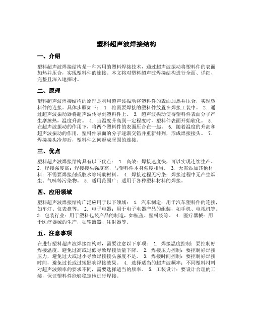
四、应用领域塑料超声波焊接结构广泛应用于以下领域: 1. 汽车制造:用于汽车塑料件的连接,如车灯、仪表盘等。
2. 电子电器:用于电子电器产品的组装,如手机、电视机等。
3. 包装行业:用于塑料包装产品的制造,如瓶盖、塑料袋等。
4. 医疗器械:用于医疗器械的生产,如输液器、注射器等。
五、注意事项在进行塑料超声波焊接结构时,需要注意以下事项: 1. 焊接温度控制:要控制好焊接温度,避免过高或过低导致焊接质量下降。
2. 焊接压力控制:要控制好焊接压力,避免过大或过小导致焊接接头强度不足。
3. 焊接时间控制:要控制好焊接时间,避免过长或过短影响焊接效果。
4. 选择适当的超声波频率:不同塑料材料对超声波频率的要求不同,需要选择适当的频率。
超声波焊接头设计方法

超声波焊接头设计方法超声波焊接头的设计需要遵循一些关键原则和步骤,以确保其能有效地将超声波能量传递到待焊接的材料上,同时避免对材料造成损伤。
以下是一些设计超声波焊接头的基本步骤和注意事项:1. 确定应用需求:首先,需要明确焊接头的应用需求,例如焊接的材料类型、焊接的厚度、焊接的速度等。
这些参数将直接影响焊接头的设计。
2. 选择合适的材料:根据应用需求,选择能够承受超声波振动和高温的合适材料,同时确保材料具有良好的声学特性和耐腐蚀性。
3. 设计合适的结构:焊接头的结构应该能够有效地将超声波能量传递到待焊接的材料上,同时避免过度加热或损伤材料。
可以考虑使用不同的振动模式、振幅和频率来优化焊接头的结构。
4. 确定合适的尺寸:根据应用需求和材料特性,确定焊接头的直径、长度和振幅等参数。
这些参数将直接影响焊接头的效率和效果。
5. 优化设计:通过实验和仿真,对焊接头的设计进行优化,以提高其效率和可靠性。
可以尝试不同的材料、结构和参数组合,以找到最佳的设计方案。
6. 测试和验证:在生产之前,对焊接头进行测试和验证,以确保其性能符合要求。
测试可以包括焊接效果、效率、寿命等方面的评估。
7. 考虑安全性:在设计和测试过程中,应始终考虑安全性。
确保焊接头不会对操作员或材料造成伤害,同时遵循相关的安全标准和规范。
8. 优化生产工艺:在生产过程中,应考虑焊接头的可制造性和成本。
选择合适的制造工艺和材料,以确保焊接头的质量和效率,同时控制生产成本。
总之,超声波焊接头的设计需要综合考虑应用需求、材料特性、结构、尺寸、优化设计、测试和验证、安全性以及生产工艺等多个方面。
通过不断尝试和改进,可以找到最佳的设计方案,提高焊接的效率和可靠性。
超声波焊接技术PPT课件.ppt
焊头接触
耦合面
太小
正确
不正确
焊头接触
增加法兰以便焊头 直接位于焊接区域 上
超声波模具設計和应用对焊接效 果産生什庅作用
?
• 換能器 • 調幅器 • 焊头 • 底座
模具技术
压电陶瓷
H H
通电前
通电后
标准振幅
可能损坏的原因
✓ 横向振动 ✓过热 ✓撞击 ✓焊头频率相差大 ✓不適當調幅器
什么是调幅器 ?
剪切接口的局限
需要紧密公差 需要刚性侧壁支撑 零件尺寸 不规则外形
塑膠件焊接線設計外,還需要考 慮其它因素吗
?
其它设计考虑因素
尖角 孔洞和弯曲 附加物 振动膜 焊头接触
尖角
避免
推荐
孔洞和弯曲
焊头
空洞
潜在的焊接盲区
半结晶型树脂
无定型树 脂
附加物
焊头
潜在的裂纹点
附加物
振动膜
焊接时间改小 振幅加大或减小 Amplitude ProfilingTM 焊头中心柱塞 内壁加厚 内部支撑筋
调幅器是铝合金或钛合金材料制成的一 个半波长共振部分。它安置于换能器和焊头 之间,调节传递至焊头的振动幅度。
调幅器的增益
1:0.6
1:1
1:1.5
1:2.0
1:2.5
1:0.6
1:1
1:1.5
1:2.0
能量 = 功率 X 时间
功率因素
力
X
速率
力可以改变
速率因素
压强
下降速率
频率 X 振幅
负 载
黑色 银色
压力
金色
无调幅 器
如何选择调幅器
• 可咨询本公司应用部 • 超声焊头有其相应的调幅器增益极限 • 工件塑膠特性,面積大少,形狀------振幅 • 应用之種類---铆焊,点焊,嵌插焊等
超声波焊接在防水产品中的应用及设计优化

超声波焊接在防水产品中的应用及设计优化随着科技的发展,超声波焊接技术在工业生产中得到了广泛的应用。
在一些特殊的领域中,比如防水产品的制造中,超声波焊接技术更是发挥着重要的作用。
本文将针对超声波焊接在防水产品中的应用及设计优化进行探讨,希望能为相关领域的从业者提供一定的参考。
1. 超声波焊接技术超声波焊接是利用超声波在焊件表面产生的振动来达到焊接目的的一种焊接技术。
它是利用超声波的振动传递到焊接件的焊接面上,使焊接面发生相对振动,经过短暂的时间产生的摩擦使得焊接面的温度升高,从而实现焊接。
超声波焊接具有焊接速度快、焊接强度高、热影响区小等优点,因此在防水产品的生产中得到了广泛应用。
2. 防水产品的超声波焊接应用随着人们对产品防水性能的要求越来越高,防水产品的生产也成为了一个重要的领域。
例如手机壳、手表表带、防水袋等产品,都需要通过焊接来保证其防水性能。
超声波焊接技术正是在这些产品的生产中得到了广泛的应用。
利用超声波焊接技术,可以在不损坏产品外观的情况下,将产品的零部件焊接在一起,从而保证产品的防水性能。
超声波焊接具有焊接速度快、适用范围广、焊接强度高等特点。
在防水产品的生产中,正是这些特点使得超声波焊接技术得到了广泛的应用。
在手机壳的生产中,超声波焊接可以快速且精确地焊接产品的零部件,从而保证产品的完整性和防水性能。
而且,超声波焊接技术可以减少产品在生产过程中的热变形和热影响区,从而提高产品的质量和稳定性。
1. 材料选择优化在防水产品的生产中,材料的选择是至关重要的。
为了保证产品的防水性能,需要选择适合超声波焊接的材料。
一般来说,熔点低、导热性好、具有一定硬度和韧性的材料更适合超声波焊接。
在设计防水产品的时候,需要充分考虑材料的选择,以便更好地实现超声波焊接。
2. 结构设计优化在设计防水产品的零部件结构时,需要充分考虑超声波焊接的特点,合理设计焊接接头的形状和位置。
避免设计过大的焊接接头,以免影响产品的外观和防水性能。
超声波焊接手册

.0《焊接手册》第一册第31章超声波焊接作者齐志扬审者李致焕31.1概述超声波焊是利用超声频率(超过16KH Z)的机械振动能量在静压力的共同作用下,连接同种或异种金属、半导体、塑料及金属陶瓷等的特殊焊接方法。
金属超声波焊接时,既不向工件输送电流,也不向工件引入高温热源,只是在静压力下将弹性振动能量转变为工件间的摩擦功、形变能及随后有限的温升。
接头间的冶金结合是在母材不发生熔化的情况下实现的,因而是一种固态焊接。
31.1.1工作原理典型的超声波焊接系统见图31-1图31-1超声波焊原理1-发生器2-换能器3-传振杆4-聚能器5-耦合杆6-静载7-上声极(焊头)8-工件9-下声极(焊座)F-静压力V1-纵向振动方向V2-弯曲振动方向由上声极传输的弹性振动能量是经过一系列的能量转换及传递环节产生的,这些环节中,超声波发生器是一个变频装置,它将工频电流转变为超声波频率(15~60KHZ)的振荡电流。
换能器则利用逆压电效应转换成弹性机械振动能。
传振杆、聚能器用来放大振幅,并通过耦合杆上声极传递到工件。
换能器、传振杆、聚能器、耦合杆及上声极构成一个整体,称之为声学系统。
声学系统中各个组元的自振频率,将按同一个频率设计,当发生器的振荡电泫频率与声学系统的自振频率一致时,系统即产生谐振(共振),并向工件输出弹性振动能。
31.1.3超声波焊的机理(1)超声波焊焊缝的形成主要由振动剪切力、静压力和焊区的温升三个因素所决定。
综观焊接过程,超声波焊经历了如下三个阶段。
摩擦:超声波焊的第一个过程主要是磨擦过程,其相对磨擦速度与磨擦焊相近只是振幅仅仅为几十微米。
这一过程的主要作用是排除工件表面的油污、氧化物等杂质,使纯净的金属表面暴露出来。
(2)应力及应变过程:从光弹应力模型中可以看到剪切应力的方向每秒将变化几千次,这种应力的存在也是造成磨擦过程的起因,只是在工件间发生局部连接后,这种振动的应力和应变将形成金属间实现冶金结合的条件。
钢结构焊接接头超声波检测作业指导书

钢结构焊接接头超声波检测作业指导书钢结构在建筑工程中广泛使用,而钢构件之间的焊接则是连接关键。
焊接质量的好坏直接影响到钢结构建筑的安全性和稳定性。
为确保焊接质量,超声波检测是一种非常有效的方法。
本文将详细介绍钢结构焊接接头超声波检测的作业指导书,以确保焊接质量。
一、超声波检测原理超声波检测是一种利用超声波的特性来检测工件中缺陷或杂质的一种检测技术。
当超声波从材料表面传播进入材料内部时,它会与材料中的缺陷反射或散射。
超声波检测器将波形转换成图像,显示需要检测的部位。
如果波形显示有缺陷,则说明超声波遇到了缺陷区域。
建议选用A、B扫描或C扫描方式进行检测。
在A、B扫描模式中,超声波探头在被测结构上扫描,工作时需要对照标准进行扫描。
在C扫描模式下,超声波探头在被测物体中进行扫描,然后光电管或CRT显示扫描在X-Y平面内的分布情况。
二、操作步骤1.检测设备选型应使用检测灵敏度好、抗干扰性能高的超声波检测仪。
2.检测人员的选择需要具备一定的技能和才能。
建议选用持证或有实践经验的人员进行检测。
3.检测表面的预处理检测时应确保被测部位表面干净、光滑,无影响测量的质料和气泡。
4.探头的选择根据被测部位和超声波检测需要,正确选择探头及角度。
5.超声波检测能量及参数的选择应根据被测材料的厚度及探头的频率,选择合适的检测能量和参数。
6.校准标准块校准前应先对所选探头进行空气校准,然后进行标准块的校准。
标准块应具有与被测材料相似的声速和材质。
7.检测作业在检测时,探头应与被测部位的表面垂直,探头面应与被检测材料表面紧密贴合。
在检测作业时,应具备抽检、全检、跳检等不同校验方法,严格按照规范、标准的数据记录方式和要求填写检测报告。
三、注意事项1.操作人员应持证或有实践经验;2.被测部位表面必须干净、光滑;3.探头选择合适,并严格校准探头;4.检测时应根据被测材料的厚度及探头的频率,选择合适的检测能量和参数;5.严格遵守规范、标准的数据记录方式和要求填写检测报告。
T型接头焊缝的超声波检测要点

毕业论文毕业设计论文设计(论文)题目:T型焊缝的超声波检测下达日期:2011 年12 月 5 日开始日期:2011 年12 月 5 日完成日期:2011 年 1 月 5 日指导教师:李红莉学生专业:检测技术及应用班级:检测0901学生姓名:安克珍教研室主任:张博材料工程系陕西工业职业技术学院毕业设计(论文)任务书毕业设计题目:T型焊缝的超声波检测进程计划表(安克珍)序号起止日期计划完成内容实际完成情况检查签名1 2011.12.5~12.7查资料、分组完成2 2011.12.8~12.9课外查资料为撰写论文做准备完成3 2011.12.12~12.15模拟机仪器性能的测试完成4 2011.12.16~2011.12.18距离-波幅曲线的绘制完成5 2011.12.19~2011.12.20探伤工艺的选择和确定完成6 2011.12.21~2011.12.23对工件进行超声波检测完成7 2011.12.24~2011.12.28整理各类资料,将论文撰写完毕,进行初稿修正完成8 2011.12.29~2012.1.5修改论文准备答辩完成T型焊缝的超声波检测摘要:介绍了T型角焊缝超声波探伤的两种方法:单直探头法和单斜探头法。
对直探头探测频率和斜探头K值选择及模拟机的基本性能测试进行了简单论述; 着重分析了探伤中出现的波形及依据波形特征确定缺陷位置, 并对缺陷性质作出判断的分析方法,为实际检测提供依据,并通过检验实例来证明检测效果。
关键词:超声波检测,T型角焊缝,探头,波形,缺陷T TYPE ULTRASONIC TESTING OF WELDS ABSTRACT:Introduced T ultrasonic flaw detection of two kinds of methods: single straight probe method and monoclinic probe method. On straight beam probe detection frequency and K value of angle probe selection and simulation machine basic performance test is simply discussed; analyzes the flaw in the waveform and based on the waveform characteristics determine the defect position, and on the nature of defect judgement analysis method, provide the basis for the actual testing, and through the test example to demonstrate the detection effect.KEY WORDS:Ultrasonic testing, T type fillet weld, probe, wave,前言:T 型角焊缝是一种常见的焊接结构,在金属结构件中应用非常广泛。
浅谈超声波焊接塑料件的设计塑料件
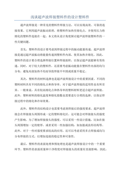
浅谈超声波焊接塑料件的设计塑料件超声波焊接是一种常见的塑料件焊接方法,可以实现高效、可靠的连接效果。
它利用超声波振动原理,将塑料件加热至熔化点,并使用压力将熔化的塑料件连接在一起。
本文将从设计角度探讨超声波焊接塑料件的一些关键问题。
首先,塑料件的设计要考虑到焊接过程中的振动能量传递。
超声波焊接是通过超声波振动将能量传递到塑料件内部,使其加热并熔化。
因此,塑料件的设计要合理选择焊接位置和焊接面积,以保证超声波能够有效传递。
同时,对于较大的塑料件,还需要考虑振动能量在塑料件内部的均匀分布,避免局部加热不均而导致焊接不牢固或质量不稳定。
其次,塑料件的材料选择也是超声波焊接设计中的重要因素。
不同的塑料材料具有不同的熔化点和热导率,对于超声波焊接的适用性也有所差异。
一般来说,具有较高熔化点和热导率的塑料材料更适合超声波焊接。
此外,塑料材料的熔化温度和熔化指数也需要进行合理的选择,以保证焊接过程中的熔化和冷却效果。
此外,塑料件的结构设计也需要考虑到焊接后的强度要求。
超声波焊接会在焊接接头周围形成一定的塑料熔化区,这可能会对焊接接头的强度产生影响。
为了增加焊接接头的强度,可以采用一些设计措施,比如在接头周围增加一定的壁厚,或者采用一些加强结构,如加筋或齿形结构等。
此外,对于一些对强度要求较高的应用,还可以考虑采用多点焊接或均匀分布焊接的方式,以增加连接的稳定性和可靠性。
最后,塑料件的表面处理和预处理也是超声波焊接设计中的一个重要环节。
塑料件的表面质量和干净程度对焊接接头的质量有直接影响。
因此,在进行超声波焊接之前,需要对接头表面进行适当的处理,如去除油污、杂质和氧化层等。
此外,还可以考虑采用一些增粘剂或者使用专用的焊接剂,以提高焊接接头的质量和品质。
总而言之,超声波焊接塑料件的设计需要综合考虑焊接过程中的振动能量传递、塑料材料的选择、结构设计的强度要求、表面处理和预处理等因素。
通过合理的设计,可以实现高效、稳定和可靠的超声波焊接效果,为塑料件的应用提供可靠的连接方式。
- 1、下载文档前请自行甄别文档内容的完整性,平台不提供额外的编辑、内容补充、找答案等附加服务。
- 2、"仅部分预览"的文档,不可在线预览部分如存在完整性等问题,可反馈申请退款(可完整预览的文档不适用该条件!)。
- 3、如文档侵犯您的权益,请联系客服反馈,我们会尽快为您处理(人工客服工作时间:9:00-18:30)。
SEE- IN ULTRASONIC SDN. BHD.( Company No. : 750998 – H )Lot 25-4-10, Plaza Prima,Batu 4 1/2, Jalan Klang Lama,58200 Kuala Lumpur, Malaysia.Tel : 03-7982 6466 Fax: 03–7982 6468Joint Designs for Ultrasonic WeldingPerhaps the most critical facet of ultrasonic welding is joint design(the configuration of two mating surfaces). It should be considered when the parts to be welded are still in the design stage, and incorporated into the molded parts. There are a variety of joint designs, each with specific features and advantages. Their selection is determined by such factors as type of plastic, part geometry, weld requirements, machining and molding capabilities, and cosmetic appearance.Butt Joint with Energy DirectorThe butt joint with energy director is the most common joint design used in ultrasonic welding, and the easiest to mold into a part. The main feature of this joint is a small 90" or 60" triangular shaped ridge molded into one of the mating surfaces. This energy director limits initial contact to a very small area, and focuses the ultrasonic energy at the apex of the triangle. During the welding cycle, the concentrated ultrasonic energy causes the ridge to melt and the plastic to flow throughout the joint area, bonding the parts together.For easy-to-weld resins (amorphous polymers such as ABS, SAN, acrylic and polystyrene) the size of the energy director is dependent on the area to be joined. Practical considerations suggest a minimum height between .008 and .025 inch (.2 and .6 mm).Crystalline polymers, such as nylon, thermoplastic polyesters, octal, polyethylene, polypropylene, and polyphenylene sulfide, as well as high melt temperature amorphous resins, such as polycarbonate and polysulfide are more difficult to weld. For these resins, energy directors with a minimum height between .015 and, 020 inch (.4 and .5 mm) with a 60" included angle are generally recommended.The 90" included angle energy director height should be at least 10% of the joint width, and the width of the energy director should be at least 20% of the joint width. Image 1 (to the right) shows a butt joint with a 90" included angle energy director. With thick-walled joints, two or more energy directors should be used, and the sum of their heights should equal 10% of the joint width.To achieve hermetic seals when welding poly-carbonate components, it is recommended that a 60" included angle energy director should be designed into the part. The energy director width should be 25% to 30% of the wall thickness. Image 2 (to the right) shows a butt joint with a 60" included angle energy director. Image 3 (to the right) shows how the ports should be dimensioned to allow for the flow of molten material from the energy director throughout the joint area.With assemblies whose components are mode of identical thermoplastics, the energy director can be designed into either half of the assembly. However, when designing energy directors into assemblies consisting of a part mode of copolymers or terpolymers, such as ABS, and another part made of a photopolymer such as acrylic, the energy director should always be incorporated into the photopolymer half of the assembly. Thermoplastic Assembly Solutions for EveryApplication:Step Joint with Energy DirectorThe step joint with energy directory is illustrated in Image 4 (to the right). This joint molds readily, and provides a strong, well aligned joint with a minimum of effort. This joint is usually stronger than a butt joint due to the fact that material flows into the verticalclearance. The step joint provides good strength in shear as well as tension, and is often recommended where good cosmeticappearance is required. When working with crystalline materials a 60° included angle energy director should be used instead of the 90° included angle energy director.Image 5 (below) shows variations of the basic step jointdesign.Tongue and Groove Joint with Energy DirectoryThe tongue and groove joint with energy director is illustrated in Image 6 (to the right). This joint is used primarily for scan welding, self location of parts, and prevention of flash both internally and externally. It provides the greatest bond strength of the three joints discussed so far. Shear JointThe shear joint of interference joint shown in figure 7 is generally recommended for high-strengths hermetic seals of parts with square corners or rectangular designs, especially with crystalline resins.Initial contact is limited to a small area which is usually a recess or step in either of the parts. The contacting surfaces melt first. As the parts telescope together, they continue to melt along the vertical walls. The smearing action of these two melt surfaces eliminates leaks and voids, making this the best joint for strong hermetic seals. Several important aspects of the shear joint should be considered 1) the top part should be as shallow as possible, 2) the outer walls should be well supported by a holding fixture, 3) the design should allow for a clearance fit, and 4) a lead-in (A) should be incorporated.The shear joint requires weld times in the range of 3-4 times that of other joint designs because larger amounts of resin are being welded. In addition, a certain amount of flash will be visible on the surface after welding.Image: 4Image: 6Image: 7Scarf JointThe scarf joint, illustrated in Image 11, is generally recommended to high-strength hermetic seals on parts with circular or ovaldesigns, especially with crystalline resins.Image: 11The scarf joint requires that the angles of the two parts be between 30' and 60' and be within one and one half degrees. If the wallthickness is .025" (0.63mm) or less, an angle of 60' should be used. If the wall thickness is .060" (1.52mm) or more, an angle of 30' should be used. Intermediate angles are recommended for wall thickness between .025" and .060" (.063 and 1.52mm).A minimum wall thickness of .030" (0.76mm) at the outer edge of the scarf is recommended to prevent "blowout," or melting clear through the wall, during welding.The scarf joint is not commonly used due to the difficulties encountered in maintaining component concentricity anddimensional tolerances. However, this joint is highly recommended when limited wall thickness preclude the use of a shear or modified shear joint.A modified scarf joint is illustrated in Image 12.As shown in Figure 13, a flash well can be incorporated in the scarf joint to contain the excess molten material generated when the parts are welded. The length of the well should be at least equal to the cross sectional thickness of the part being welded.Image: 8Image: 9Image: 12。