格力多联机设计选型手册R410A
格力(气液)制冷剂配管尺寸

R410A制冷剂系统
室内机能力
气管(mm)
液管(mm)
22、25、28型
φ9.52
φ6.35
36、40、45、50型
φ12.7
φ6.35
56、63、71、80、90、100、112、125、140型
φ15.9
φ9.52
Φ9.52
300<C≤450
Φ28.6
Φ12.7
450<C≤670
Φ28.6
Φ15.9
670<≤950
Φ34.9
Φ19.05
950<C≤1350
Φ41.3
Φ19.05
1350<C≤1600
Φ44.5
Φ22.2
1600<C≤2100
Φ54.1
Φ25.4
4.3分歧部至室内机间的配管(室内配管)尺寸同室内机配管尺寸相同,尺寸如下表所示:
R410A制冷剂配管尺寸(Pd/Pdm系列)
4.1室外机至第1分歧间的配管(主管)尺寸由室外机容量代码来确定
室外机至第1分歧间配管尺寸
R410A制冷剂系统
室外机容量C
气管(mm)
液管(mm)
C≤50
Φ12.7
Φ6.35
50<C≤140①
Φ15.9
Φ9.52
140<C≤180
Φ19.05
Φ9.52
C≤280
Φ22.2
Φ9.52
280<C≤450
Φ28.6
Φ12.7
450<C≤670
Φ28.6
Φ15.9
670<C≤950
Φ34.9
Φ19.1
950<C≤1350
格力多联机GMV内机(R410A)H系列.

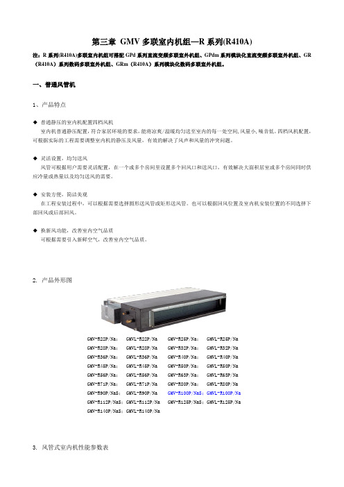
第三章GMV多联室内机组—R系列(R410A)注:R系列(R410A)多联室内机组可搭配GPd系列直流变频多联室外机组、GPdm系列模块化直流变频多联室外机组、GR (R410A)系列数码多联室外机组、GRm(R410A)系列模块化数码多联室外机组。
一、普通风管机1、产品特点◆普通静压的室内机配置四档风机室内机普通静压配置,符合家居环境的要求,能将凉爽/温暖均匀送至室内的每一处空间,风量小,噪音低。
四档风机配置,可根据实际的工程需要调整室内机的静压及风量,有效的解决了风声和风量的冲突问题。
◆灵活设置,均匀送风风管可根据用户需要灵活配置,在一个或多个房间里设置多个回风口和送风口,有效解决大面积居室或多个房间同时供应冷量或热量以及均匀送风的需要。
◆安装方便,简洁美观在工程安装过程中,可以根据需要选择圆形送风管或矩形送风管。
也可以根据回风位置及室内机安装位置的不同选择下部回风或后部回风。
◆换新风功能,改善室内空气品质可根据需要引入新鲜空气,改善室内空气品质。
2. 产品外形图GMV-R22P/Na; GMVL-R22P/Na GMV-R25P/Na; GMVL-R25P/NaGMV-R28P/Na; GMVL-R28P/Na GMV-R32P/Na; GMVL-R32P/NaGMV-R36P/Na; GMVL-R36P/Na GMV-R40P/Na; GMVL-R40P/NaGMV-R45P/Na; GMVL-R45P/Na GMV-R50P/Na; GMVL-R50P/NaGMV-R56P/Na; GMVL-R56P/Na GMV-R63P/Na; GMVL-R63P/NaGMV-R71P/Na; GMVL-R71P/Na GMV-R80P/Na; GMVL-R80P/NaGMV-R90P/NaS; GMVL-R90P/Na GMV-R100P/NaS;GMVL-R100P/NaGMV-R112P/NaS;GMVL-R112P/Na GMV-R125P/NaS;GMVL-R125P/NaGMV-R140P/NaS;GMVL-R140P/Na3. 风管式室内机性能参数表注:a. 本机组设计执行标准GB/T 18837-2002。
格力多联机GMV内机(R410A)H系列
连接管
气管
mm
Φ9.52
Φ9.52
Φ12.7
Φ12.7
Φ12.7
液管
mm
Φ6.35
Φ6.35
Φ6.35
Φ6.35
Φ6.35
连接方式
喇叭口连接
排水管(外径×壁厚)
mm
Φ20×1.5
Φ30×1.5
尺寸
(宽×深×高)
mm
875×680×220
980×736×266
净重
kg
27
36
注:a. 本机组设计执行标准GB/T18837-2002。
GMV-R28P/Na; GMVL-R28P/Na GMV-R32P/Na; GMVL-R32P/Na
GMV-R36P/Na; GMVL-R36P/Na GMV-R40P/Na; GMVL-R40P/Na
GMV-R45P/Na; GMVL-R45P/Na GMV-R50P/Na; GMVL-R50P/Na
GMV-R56P/Na; GMVL-R56P/Na GMV-R63P/Na; GMVL-R63P/Na
GMV-R71P/Na; GMVL-R71P/Na GMV-R80P/Na; GMVL-R80P/Na
GMV-R90P/NaS; GMVL-R90P/NaGMV-R100P/NaS;GMVL-R100P/Na
室内机普通静压配置,符合家居环境的要求,能将凉爽/温暖均匀送至室内的每一处空间,风量小,噪音低。四档风机配置,可根据实际的工程需要调整室内机的静压及风量,有效的解决了风声和风量的冲突问题。
◆ 灵活设置,均匀送风
风管可根据用户需要灵活配置,在一个或多个房间里设置多个回风口和送风口,有效解决大面积居室或多个房间同时供应冷量或热量以及均匀送风的需要。
R410A分离式空调系列用户手册说明书
INSTALLATION MANUALR410A Split SeriesModelsFTXS20G2V1B FTXS25G2V1B FTXS35G2V1B FTXS42G2V1BFTXS50G2V1BDeutschFrançaisNederlandsEspañolItalianoΕλληνικÜPortuguesРóссêийEnglishTürkçeInstallation manual R410A Split series Montaj kýlavuzlarý R410A Split serisiInstallationsanleitung Split-Baureihe R410A Manuel d’installation Série split R410A Montagehandleiding R410A Split-systeem Manual de instalaciónSerie Split R410A Manuale d’installazione Serie Multiambienti R410A Εγχειρßδιο εγκατÜστασηòδιαιροýìενηò σειρÜò R410AManual de Instalação Série split R410AРóêоводство по монтажóСерия R410A с раздельной óстановêойU m e d a C e n t e r B l d g ., 2-4-12, N a k a z a k i -N i s h i ,K i t a -k u , O s a k a , 530-8323 J a p a n0G 2V 1B , F T X S 25G 2V 1B , F T X S 35G 2V 1B , F T X S 42G 2V 1B , F T X S 50G 2V 1BI N I N D U S T R I E S , L T D .S h i n r i S a d a M a n a g e r Q u a l i t y C o n t r o l D e p a r t m e n t 1s t . o f N o v . 2008L o w V o l t a g e 2006/95/E C E l e c t r o m a g n e t i c C o m p a t i b i l i t y 2004/108/E C *D A I K I N .T C F .015 L 3/08-2007K E M A Q u a l i t y B .V .74736-K R Q /E M C 97-4957Safety Precautions•The precautions described herein are classified as WARNING and CAUTION. They both contain important informa-tion regarding safety. Be sure to observe all precautions without fail.•Meaning of WARNING and CAUTION noticesWARNING....Failure to follow these instructions properly may result in personal injury or loss of life.CAUTION.....Failure to observe these instructions properly may result in property damage or personal injury, which may be serious depending on the circumstances.•The safety marks shown in this manual have the following meanings:Be sure to follow the instructions. Be sure to establish an earth connection. Never attempt.•After completing installation, conduct a trial operation to check for faults and explain to the customer how to operate the air conditioner and take care of it with the aid of the operation manual.WARNING•Ask your dealer or qualified personnel to carry out installation work.Do not attempt to install the air conditioner yourself. Improper installation may result in water leakage, electric shocks or fire.•Install the air conditioner in accordance with the instructions in this installation manual.Improper installation may result in water leakage, electric shocks or fire.•Be sure to use only the specified accessories and parts for installation work.Failure to use the specified parts may result in the unit falling, water leakage, electric shocks or fire.•Install the air conditioner on a foundation strong enough to withstand the weight of the unit.A foundation of insufficient strength may result in the equipment falling and causing injury.•Electrical work must be performed in accordance with relevant local and national regulations and with instructions in this installation manual. Be sure to use a dedicated power supply circuit only.Insufficiency of power circuit capacity and improper workmanship may result in electric shocks or fire.•Use a cable of suitable length.Do not use tapped wires or an extension lead, as this may cause overheating, electric shocks or fire.•Make sure that all wiring is secured, the specified wires are used, and that there is no strain on the terminal con-nections or wires.Improper connections or securing of wires may result in abnormal heat build-up or fire.•When wiring the power supply and connecting the wiring between the indoor and outdoor units, position the wires so that the control box lid can be securely fastened.Improper positioning of the control box lid may result in electric shocks, fire or over heating terminals.•If refrigerant gas leaks during installation, ventilate the area immediately.Toxic gas may be produced if the refrigerant comes into contact with fire.•After completing installation, check for refrigerant gas leakage. Toxic gas may be produced if the refrigerant gas leaks into the room and comes into contact with a source of fire, such as a fan heater, stove or cooker.•When installing or relocating the air conditioner, be sure to bleed the refrigerant circuit to ensure it is free of air, and use only the specified refrigerant (R410A).The presence of air or other foreign matter in the refrigerant circuit causes abnormal pressure rise, which may result in equipment damage and even injury.•During installation, attach the refrigerant piping securely before running the compressor.If the compressor is not attached and the stop valve is open when the compressor is run, air will be sucked in, causing abnormal pressure in the refrigeration cycle, which may result in equipment damage and even injury.•During pump-down, stop the compressor before removing the refrigerant piping.If the compressor is still running and the stop valve is open during pump-down, air will be sucked in when the refrigerant piping is removed, causing abnormal pressure in the refrigeration cycle, which may result in equipment damage and even injury.•Be sure to earth the air conditioner. Do not earth the unit to a utility pipe, lightning conductor or telephone earth lead.Imperfect earthing may result in electric shocks.•Be sure to install an earth leakage breaker.Failure to install an earth leakage breaker may result in electric shocks or fire.CAUTION•Do not install the air conditioner at any place where there is a danger of flammable gas leakage.In the event of a gas leakage, build-up of gas near the air conditioner may cause a fire to break out.•While following the instructions in this installation manual, install drain piping to ensure proper drainage and insu-late piping to prevent condensation.Improper drain piping may result in indoor water leakage and property damage.•Tighten the flare nut according to the specified method such as with a torque wrench.If the flare nut is too tight, it may crack after prolonged use, causing refrigerant leakage.AccessoriesChoosing an Installation Site•Before choosing the installation site, obtain user approval.1.Indoor unit.•The indoor unit should be sited in a place where:1)the restrictions on installation specified in the indoor unit installation drawings are met,2)both air intake and exhaust have clear paths met,3)the unit is not in the path of direct sunlight,4)the unit is away from the source of heat or steam,5)there is no source of machine oil vapour (this may shorten indoor unit life),6)cool (warm) air is circulated throughout the room,7)the unit is away from electronic ignition type fluorescent lamps (inverter or rapid start type) as they may shorten the remote controller range,8)the unit is at least 1 metre away from any television or radio set (unit may cause interference with the picture or sound),9)install at the recommended height (1.8m).2.Wireless remote controller.1)Turn on all the fluorescent lamps in the room, if any, and find the site where remote controller signals are properly received by the indoor unit (within 7 metres).2)Make the dipswitch settings. Set according to the type of unit purchased by the customer. The default settings are on the heat pump side.•For cooling only (Outdoor unit model: RKS)Set the dipswitches on the cooling only side.•For heat pump (Outdoor unit model: RXS)Check that the dipswitches are on the heat pump side.If they are set on the cooling only side, move them to the heat pump side.Installation Tips1.Removing and installing front panel.•Removal methodHook fingers on the panel protrusions on the left and right of the main body, and open until the panel stops. Slide the front panel sideways to disengage the rotating shaft. Then pull the front panel toward you to remove it.•Installation method2.Removing and installing front grille.•Removal method1)Remove front panel to remove the air filter.2)Remove the front grille.3)In front of the {{{of your other hand.When there is no work space because the unit is close to ceilingCAUTIONBe sure to wear protection gloves.Place both hands under the center of the front grille, and while pushing up, pull it toward you.•Installation method1)Install the front grille and firmly engage the upper hooks (3 locations).2)Install 2 screws of the front grille.3)Install the air filter and then mount the front panel.3.How to set the different addresses.When 2 indoor units are installed in 1 room, the 2 wireless remote controllers can be set for different addresses.1)Remove the metal plate electrical wiring cover.(Refer to the Removal/attachment methods of metal plate electrical wiring covers .)2)Cut the address jumper (JA) on the printed circuit board.3)Cut the address jumper (J4) in the remote controller.4.When connecting to an HA system.(Wired remote controller, central remote controller etc.)1)Remove the metal plate electrical wiring cover.(Refer to the Removal/attachment methods of metal plate electrical wiring covers .) 2)Attach the connection cord to the S21 connector and pull theharness out through the notched part in the figure.3)as it was, and pull the harness around, as shown in the figure.Installation TipsIndoor Unit Installation DrawingsCAUTION1)Do not hit or violently push the Intelligent-eye sensor. This can lead to damage and malfunction.2)Do not place large objects near the sensor. Also keep heating units or humidifiers outside the sensor’s detection area.Indoor Unit Installation1.Installing the mounting plate.•The mounting plate should be installed on a wall which can support the weight of the indoor unit.1)Temporarily secure the mounting plate to the wall, make sure that the panel is completely level, and mark the boringpoints on the wall.2)Secure the mounting plate to the wall with screws.Recommended mounting plate retention spots and Dimensions2.Boring a wall hole and installing wall embedded pipe.•For walls containing metal frame or metal board, be sure to use a wallembedded pipe and wall cover in the feed-through hole to prevent possible heat, electrical shock, or fire.•Be sure to caulk the gaps around the pipes with caulking material to prevent water leakage.1)Bore a feed-through hole of 65mm in the wall so it has a down slope toward the outside.2)Insert a wall pipe into the hole.3)Insert a wall cover into wall pipe.4)After completing refrigerant piping, wiring, and drain piping, caulk pipe hole gap with putty.3.Installing indoor unit.3-1.Right-side, right-back, or right-bottom piping.1)Attach the drain hose to the underside of the refrigerant pipes with an adhesive vinyl tape.2)Wrap the refrigerant pipes and drain hose together with an insulation tape.3)4)(Refer to Installation tips.)5)tape.)6)catch on the edge of the indoor unit.Indoor Unit Installation3-2.Left-side, left-back, or left-bottom piping.1)Attach the drain hose to the underside of the refrigerant pipes with adhesive vinyl tape.2)Be sure to connect the drain hose to the drain port in place of a drain plug.3)Shape the refrigerant pipe along the pipe path marking on the mounting plate.4)Pass drain hose and refrigerant pipes through the wall hole, then set the indoor unit on mounting guide.5)Pull in the interconnecting wires.6)Connect the inter-unit piping.7)Wrap the refrigerant pipes anddrain hose together with insulation tape as right figure, in case of setting the drain hose through the back of the indoor unit.8)While exercising care so that the interconnecting wires do not catch indoor unit, press the bottom edge of indoor unit with both hands until it is firmly caught by the mounting plate hooks. Secure indoor unit to the mounting plate with screws (M4 × 12L).3-3.Wall embedded piping.Follow the instructions given under 1)Insert the drain hose to this depth so it won’t be pulled out of the drain pipe..4.Wiring., install as described in the installation manual supplied with the Multi outdoor unit.1)Strip wire ends (15mm).2)Match wire colours with terminal numbers on indoor and outdoor unit’s terminal blocks and firmly screw wires to the corresponding terminals.3)Connect the earth wires to the corresponding terminals.4)Pull wires to make sure that they are securely latched up, then retain wires with wire retainer.5)In case of connecting to an adapter system. Run the remote controller cable and attach the S21.6)Shape the wires so that the service lid fits securely, then close service lid.WARNING1)Do not use tapped wires, strand wires, extensioncords, or starburst connections, as they may cause overheating, electrical shock, or fire.2)Do not use locally purchased electrical parts inside the product. (Do not branch the power for the drain pump, etc., from the terminal block.) Doing so may cause electric shock or fire.5.Drain piping.1)Connect the drain hose, as described right.2)Remove the air filters and pour some water into the drain pan to check the water flows smoothly.3)When drain hose requires extension, obtain an extension hose commercially available.Be sure to thermally insulate the indoor section of the extension hose.4)When connecting a rigid polyvinyl chloride pipe (nominal diameter 13mm) directly to the drain hose attached to the indoor unit as withembedded piping work, use any commercially available drain socket (nominal diameter 13mm) as a joint.Refrigerant Piping Work, install as described in the installation manual supplied with the Multi outdoor unit.1.Flaring the pipe end.1)Cut the pipe end with a pipe cutter.2)Remove burrs with the cut surface facing downward so that the chips do not enter the pipe.3)Put the flare nut on the pipe.4)Flare the pipe.5)Check that the flaring is properly made.WARNING1)Do not use mineral oil on flared part.2)Prevent mineral oil from getting into the system as this would reduce the lifetime of the units.3)Never use piping which has been used for previous installations. Only use parts which are delivered with the unit.4)Do never install a drier to this R410A unit in order to guarantee its lifetime.5)The drying material may dissolve and damage the system.6)Incomplete flaring may cause refrigerant gas leakage.2.Refrigerant piping.CAUTION1)Use the flare nut fixed to the main unit. (To prevent cracking of the flare nut by aged deterioration.)2)To prevent gas leakage, apply refrigeration oil only to the inner surface of the flare. (Use refrigeration oil for R410A.)3)Use torque wrenches when tightening the flare nuts to prevent damage to the flare nuts and gas leakage.Align the centres of both flares and tighten the flare nuts 3 or 4 turns by hand. Then tighten them fully with the torque wrenches.2-1.Caution on piping handling.1)Protect the open end of the pipe against dust and moisture.2)All pipe bends should be as gentle as possible. Use a pipe bender for bending.2-2.Selection of copper and heat insulation materials.•When using commercial copper pipes and fittings, observe the following:1)Insulation material: Polyethylene foamHeat transfer rate: 0.041 to 0.052W/mK (0.035 to 0.045kcal/(mh•°C))Refrigerant gas pipe’s surface temperature reaches 110°C max.Choose heat insulation materials that will withstand this temperature.2)Be sure to insulate both the gas and liquid piping and to provide insulation dimen-sions as below.3)Use separate thermal insulation pipes for gas and liquid refrigerant pipes.Pump Down OperationIn order to protect the environment, be sure to pump down when relocating or disposing of the unit.1)Remove the valve cap from liquid stop valve and gas stop valve.2)Carry out forced cooling operation.3)After 5 to 10 minutes, close the liquid stop valve with a hexagonal wrench.4)After 2 to 3 minutes, close the gas stop valve and stop forced cooling operation.How to force cooling operation mode■Using the indoor unit operation/stop buttonPress the indoor unit operation/stop button for at least 5 seconds. (Operation will start.)•Forced cooling operation will stop automatically after around 15 minutes. To force a test run to stop, press the indoor unit operation/stop button.■Using the main unit’s remote controller 1)Press the “operation/stop” button. (Operation will start.)2)Press the temperature button and the “operation select” button at the same time.3)Press the “operation select” button twice.( will be displayed and the unit will enter test run mode.)4)Press the “operation select” button to return the operation mode to cooling.•Test run mode will stop automatically after around 30 minutes. To force a test run to stop, press the operation/stop button.CAUTION1)After closing the liquid stop valve, close the gas stop valve within 3 minutes, then stop the forced operation.Gas side Liquid side Gas pipe thermal insulation Liquid pipethermal insulation 20/25/35/42 class50 class 20/25/35/42class 50 classO.D. 9.5mm O.D. 12.7mm O.D. 6.4mm I.D. 12-15mm I.D. 14-16mm I.D. 8-10mmMinimum bend radius Thickness 10mm Min.30mm or more 40mm or more 30mm or moreThickness 0.8mm (C1220T-O)Trial Operation and Testing1.Trial operation and testing.1-1Measure the supply voltage and make sure that it falls in the specified range.1-2Trial operation should be carried out in either cooling or heating mode.■For Heat pump•In cooling mode, select the lowest programmable temperature; in heating mode, select the highest programmable temperature.1)Trial operation may be disabled in either mode depending on the room e the remote controller for trial operation as described below.2)After trial operation is complete, set the temperature to a normal level (26°C to 28°C in cooling mode, 20°C to 24°C in heating mode).3)For protection, the system disables restart operation for 3 minutes after it is turned off.■For Cooling only•Select the lowest programmable temperature.1)Trial operation in cooling mode may be disabled depending on the room e the remote controller for trial operation as described below.2)After trial operation is complete, set the temperature to a normal level (26°C to 28°C).3)For protection, the unit disables restart operation for 3 minutes after it is turned off.1-3Carry out the test operation in accordance with the Operation Manual to ensure that all functions and parts,such as louver movement, are working properly.•The air conditioner requires a small amount of power in its standby mode. If the system is not to be used for some time after installation, shut off the circuit breaker to eliminate unnecessary power consumption.•If the circuit breaker trips to shut off the power to the air conditioner, the system will restore the original operation mode when the circuit breaker is opened again.2.Test items.Test itemsSymptom(diagnostic display on RC)CheckIndoor and outdoor units are installed properly on solid bases.Fall, vibration, noiseNo refrigerant gas leaks.Incomplete cooling/heating function Refrigerant gas and liquid pipes and indoor drain hose extension are thermally insulated.Water leakage Draining line is properly installed.Water leakage System is properly earthed.Electrical leakage The specified wires are used for interconnecting wire connections.Inoperative or burn damage Indoor or outdoor unit’s air intake or exhaust has clear path of air.Stop valves are opened.Incomplete cooling/heating function Indoor unit properly receives remote controller commands.InoperativeThe heat pump or cooling only mode is selectable with the dipswitches of the remote controller.Remote controller malfunctioning。
格力多联机工程设计

格力中央空调GMV多联空调机组能力修正及选型100格力中央空调GMV多联空调机组能力修正及选型101格力中央空调GMV多联空调机组能力修正及选型102格力中央空调GMV多联空调机组能力修正及选型103格力中央空调GMV多联空调机组能力修正及选型104格力中央空调A105GPd,GPdm 系列多联空调机组工程设计及安装格力中央空调A106GPd,GPdm 系列多联空调机组工程设计及安装格力中央空调A107GPd,GPdm 系列多联空调机组工程设计及安装格力中央空调A108GPd,GPdm 系列多联空调机组工程设计及安装格力中央空调A109GPd,GPdm 系列多联空调机组工程设计及安装110 AA111112 AA113114 AA115116 AA117118 AA119格力中央空调A120GPd,GPdm 系列多联空调机组工程设计及安装格力中央空调A121GPd,GPdm 系列多联空调机组工程设计及安装格力中央空调A122GPd,GPdm 系列多联空调机组工程设计及安装格力中央空调A123GPd,GPdm 系列多联空调机组工程设计及安装格力中央空调A124GPd,GPdm 系列多联空调机组工程设计及安装格力中央空调A125GPd,GPdm 系列多联空调机组工程设计及安装格力中央空调A126GPd,GPdm 系列多联空调机组工程设计及安装格力中央空调A127GPd,GPdm 系列多联空调机组工程设计及安装格力中央空调GPds系列直流变频多联空调热水机组工程设计及安装A128格力中央空调GPds系列直流变频多联空调热水机组工程设计及安装A129130 AA131132 AA133134 AA135136 AA137138 AA139格力中央空调GPds系列直流变频多联空调热水机组工程设计及安装A140格力中央空调GPds系列直流变频多联空调热水机组工程设计及安装A141格力中央空调A142GMV 多联空调机组供货范围格力中央空调A143GMV 多联空调机组供货范围格力中央空调A144GMV 多联空调机组供货范围。
格力-GPd、GPdm系列(R410A)多联机组工程设计及安装
第五章GPd、GPdm系列(R410A)多联机组工程设计及安装一、室内、外机冷媒配管设计1. 室内外机连接管的分歧方式2. Y型分歧管FQ01A、FQ01B、FQ02、FQ03、FQ04 Y型分歧管Y型分歧管可从下面的列表中选取:当下游室内机容量之和大于室外机容量时,分歧管以室外机容量进行选取。
对于FQ03或FQ04分歧管,分歧后两个支路对应的下游容量之比不能超过3:1。
举例说明:如需对下游室内机总容量代码为1000的管路进行分流,则分流后任何一侧的下游室内机容量代码之和不能小于250。
3. 室内外机冷媒配管允许长度和落差3.1容量大于等于60kW机组3.2容量大于等于20KW且小于60kW机组3.3容量小于20kW机组4. 冷媒配管尺寸4.1 室外机至第1分歧间的配管(主管)尺寸由室外机容量代码来确定室外机至第1分歧间配管尺寸4.2 分歧部至分歧部间的配管(分歧管)尺寸根据下游所接室内机容量选定。
在超过室外机容量时,以室外机容量为准。
分歧部与分歧部之间配管尺寸4.3 分歧部至室内机间的配管(室内配管)尺寸同室内机配管尺寸相同,尺寸如下表所示:室内机配管尺寸5. 冷媒配管要求5.1 本机型使用工质为R410A,冷媒配管要求不可与其他工质配管混用。
5.2 连接管管材为紫铜TP2M,满足GB/T17791-1999《空调与制冷用无缝铜管》的要求。
5.3 铜管壁厚要求:单位:mm二、室外机模块间连接配管设计注:同一系统内各模块间距不小于20mm。
1、模块连接组件对于模块化并联室外机,模块连接组件用于连接各模块之间气管和液管。
可从下面的列表中选取:2、油平衡连接三通对于三机并联油平衡管路,需在油平衡管路中连接一个接口内径均为φ9.7的油平衡连接三通。
3、室外机模块间连接配管尺寸选择3.1室外机与连接组件间配管室外机与连接组件间配管尺寸与单个模块要求配管尺寸相同。
3.2 模块连接组件间配管如室外机为三机并联,则需考虑模块连接组件间配管。
格力GMV多联空调机组室内机(R410A)
第三章 GMV多联空调机组室内机(R410A)注:GMV 多联空调机组室内机(R410A)可搭配GR 数码多联空调机组(R410A)、GRm 模块化数码多联空调机组(R410A)、GPd 直流变频多联空调机组、GPdm 模块化直流变频多联空调机组。
E 系列风管机所匹配外机仅限于直流变频机组。
双热源风管机所匹配外机仅限于直流变频模块化机组。
一、普通风管机1、产品概述室内机普通静压配置,符合家居环境的要求,能将凉爽/ 温暖均匀送至室内的每一处空间, 风量小, 噪音低。
四档风机配置,可根据实际的工程需要调整室内机的静压及风量,有效的解决了风声和风量的冲突问题。
◆灵活设置,均匀送风风管可根据用户需要灵活配置,在一个或多个房间里设置多个回风口和送风口,有效解决大面积居室或多个房间同时供应冷量或热量以及均匀送风的需要。
◆安装方便,简洁美观在工程安装过程中,可以根据需要选择圆形送风管或矩形送风管。
也可以根据回风位置及室内机安装位置的不同选择下部回风或后部回风。
◆换新风功能,改善室内空气品质可根据需要引入新鲜空气,改善室内空气品质。
2、产品外形图GMV-R22P/Na、 GMVR-R22P/ Na GMV-R25P/ Na、 GMVR-R25P/ NaGMV-R28P/ Na、 GMVR-R28P/ Na GMV-R32P/ Na、 GMVR-R32P/ NaGMV-R36P/ Na、 GMVR-R36P/ Na GMV-R40P/ Na、 GMVR-R40P/ NaGMV-R45P/ Na、 GMVR-R45P/ Na GMV-R50P/ Na、 GMVR-R50P/ NaGMV-R56P/ Na、 GMVR-R56P/ Na GMV-R63P/ Na、 GMVR-R63P/ NaGMV-R71P/ Na、 GMVR-R71P/ Na GMV-R80P/ Na、 GMVR-R80P/ NaGMV-R90P/ Na S、 GMVR-R90P/ Na GMV-R100P/ Na S、 GMVR-R100P/ NaGMV-R112P/ Na S、 GMVR-R112P/ Na GMV-R125P/ Na S、 GMVR-R125P/ NaGMV-R140P/ Na AS、GMVR-R140P/ Na A注:① .本机组设计执行标准GB/T 18837-2002。
06 GRm模块化数码多联空调机组(R410a)
第六章GRm模块化数码多联空调机组(R410a)注:GRm模块化数码多联空调机组(R410a)搭配GMV多联空调机组室内机(R410a)。
一、产品概述◆齐全的产品系列a. GRm模块化数码多联空调机组(R410a),采用模块化的技术,通过22.4、28、33.5、40、45、50.4kW 室外机的组合(可最多实现四个模块的组合),实现室外机容量最大至201.6kW。
b. 按各个房间的用途和装修特点,可以选用不同型式、不同容量的室内机,使室内装修协调美观。
可以连接的室内机有四面出风天井式、挂壁式、普通静压风管式、超薄风管式、单面出风天井式等多种机型。
◆长距离的冷媒配管a.最长配管长度可达到150m,最长配管相当长度可达175m,室内机之间落差可达15m。
b.室外机在室内机上方时,最大落差可达50m,室外机在室内机下方时,最大落差可达40m。
◆机组及压缩机轮流运行a. GRm模块化数码多联空调机组(R410a)每个模块内均有一台数码压缩机,保证了各模块的顺序启动和轮流运行功能,有效延长了整机的使用寿命。
b. 由于各模块之间可以互相替代,保证了在个别模块故障的情况下,其余模块能够正常运行并且代替故障模块进行工作,极大地增强了整个机组的运行可靠性。
◆方便的系统安装a. GRm模块化数码多联空调机组(R410a)外形紧凑,各模块之间可以并排紧密放置,减少机组所需安装空间b. GRm模块化数码多联空调系统最多可连接多达64台的室内机,极大的方便了工程设计及安装。
◆无级调速的直流变频室外风机a. 更大流量的室外风机允许机组安装在大厦的设备层内,通过导风管向外侧大气排放热量。
b. 当机组不需安装在设备层时,可降低风机功率以减少噪声。
◆全面提升的低温制热技术机组在低温制热时,仍可以保持较高的制热能力。
新型智能化霜技术,减少化霜次数及时间,增加机组的有效制热时间,有效地提高了室内的舒适程度。
◆ 智能化多联机组均油及回油运行采用精确的油位控制装置和自动均油管路系统,提供机组运行的高可靠性,确保压缩机安全运行,节约电能。
GR数码多联空调机组(R410A)
第三章GR数码多联空调机组(R410A)注:GR 数码多联空调机组室外机(R410A)搭配GMV 多联空调机组室内机(R410A)。
一、产品概述1、产品特点GR 数码多联空调机组采用新型数码涡旋容量可调压缩机技术,通过改变压缩机卸/ 负载比率实现从10% ~ 100% 范围内的容量无级调节, 在部分负荷运行时也能保持较高的能效比。
GR 数码多联空调机组有从26kW ~ 90kW 的宽广机型阵容,可广泛适用于现代家居空间、商业场所、办公环境的空气调节,尤其对负荷变化较大的使用环境,GR 数码多联中央空调是您更佳的选择。
◆采用新型环保冷媒R410A,ODP( 臭氧破坏指数) 为零,不会破坏臭氧层,有利于防止全球气候变暖。
◆所有零部件均符合RoHS 指令,更具环保性。
注:RoHS 指令的全称为《电子电气产品中限制使用某种有害物质》,2003 年2 月13 日由欧盟议会正式公布,2006 年7 月1 日起,投放欧盟市场的新的电子电气设备(豁免条款除外)中不允使用铅、汞、镉、六价铬、多溴联苯(PBB)和多溴二苯醚(PBDE)。
◆在制冷制热均能保持较高的能效比。
年平均COP 值3.5。
◆缩短制冷剂管径。
例如:24HP 机型,气管/ 液管仅为Φ28.6/Φ15.9,而R22 相同机型气管/ 液管为Φ41.3/Φ19.05。
方便配管工作,节省安装空间,节省管材材料费用。
◆智能除霜,更高效制热。
系统高压控制化霜,实现无霜不化。
用高压压力控制化霜的优点是:可以做到“无霜不化”,当在一定工况下,室外空气相对湿度小,基本不结霜,此时机组运行制热效果不受结霜的影响,机组可长时间运行不化霜。
比传统的定时化霜模式节能。
可以延长化霜时间,霜结到一定程度才化,而不是过早化霜或过晚化霜,通过高压值可客观地检测影响室内制热效果的程度。
◆制热范围低至-20℃。
◆长配管设计◆ 5 向接线和配管连接长配管设计冷媒管连接方向二、产品性能与规格1 、产品外形图GMV-R260W2/Na-N2 GMV-R450W3/Na-N1 GMV-R300W2/Na-N2GMV-R560W4/Na-N1 GMV-R860W6/Na-N1GMV-R600W4/Na-N1 GMV-R900W6/Na-N1 2、产品性能参数注:① . 本机组设计执行标准GB/T 18837-2002。
格力R410A制冷剂配管尺寸
注:当实际管长超过90米时,加大一号管径。
4.1室外机至第1分歧间的配管(主管)尺寸由室外机容量代码来确定
室外机至第1分歧间配管尺寸
室外机容量C
气管(mm)
液管(mm)
C≤50
Φ12.7
Φ6.35
50<C≤70
Φ15.9
Φ9.52
70<C≤180
Φ19.05
Φ9.52
180<C≤300
φ6.35
32、36、40、45、50型
φ12.7
φ6.35
56、63、71、80、90、10、112、125、140型
φ15.9
φ9.52
Φ34.9
Φ19.05
950<C≤1350
Φ41.3
Φ19.05
1350<C≤1600
Φ44.5
Φ22.2
1600<C≤2100
Φ54.1
Φ25.4
4.3分歧部至室内机间的配管(室内配管)尺寸同室内机配管尺寸相同,尺寸如下表所示:
室内机配管尺寸
室内机能力
气管(mm)
液管(mm)
22、25、28型
φ9.52
分歧部与分歧部之间配管尺寸
下游室内机容量代码之和X
气管(mm)
液管(mm)
C≤50
Φ12.7
Φ6.35
50<C≤70
Φ15.9
Φ9.52
70<C≤180
Φ19.05
Φ9.52
180<C≤300
Φ22.2
Φ9.52
300<C≤450
Φ28.6
Φ12.7
450<C≤670