MODEL 2061使用手册北京雪迪龙
Model 2460 快速入门指南说明书

通过速度和简化重新设计测试和测量安全注意事项在使用本产品和任何相关仪器之前,请先阅读以下安全注意事项。
虽然一些仪器和附件通常在无害电压下使用,但是也可能出现对人体有害的情况。
本产品应由能辨别电击危险且熟悉避免潜在伤害的必要安全注意事项的合格人员使用。
使用此产品之前请仔细阅读并遵守所有的安装、操作和维护信息。
有关完整的产品规格,请参阅用户文档。
若以没有指定的方式使用产品,可能丧失产品保修所提供的保障。
产品的用户类型有:责任主体,是负责使用和维护机器,确保在设备规格和运行限制范围内使用设备,并确保操作人员经过充分培训的个人或小组。
操作人员,是负责使用产品特定功能的人员。
他们必须接受过电气安全流程和正确操作仪器方面的培训。
应当采取保护措施,防止他们遭到电击和触碰到危险的带电电路。
维护人员,负责产品日常维护以保持仪器运转正常,例如,设置线路电压或更换耗材。
用户文档中描述了维护步骤。
这些步骤都清楚描述了操作人员是否能够执行它们。
如果不能,那么只能由服务人员来执行这些操作。
服务人员,接受过培训,可操作带电电路,执行安全安装并修理产品。
只有受过正确训练的服务人员才能执行安装和服务流程。
美国吉时利仪器(Keithley Instruments) 公司的产品专门设计用于测量、控制和数据输入/输出连接等电气信号,而且不能直接连接到电网电压或具有瞬时高电压的电压源上。
Measurement Category II(引自IEC 60664 标准)连接要求针对本地交流电网连接经常发生的高瞬时电压采取保护措施。
某些吉时利测量仪器可以连接到电网上。
这些仪器将会标记为Category II 或更高级别。
除非在仪器规格、操作手册和仪器标签中明示允许,否则不要将任何仪器连接到电网上。
存在电击危险时,一定要小心谨慎。
电缆连接器插头或测试装置上可能存在致命电压。
美国国家标准学会(ANSI) 规定,超过30 V RMS、42.4V峰值或60 V DC 的电压水平存在电击的危险。
Bell 206L 型号 Snow Deflector 修改手册说明书
TECHNICAL BULLETIN 206L-23-25813 June 2023MODEL AFFECTED: 206L-1, 206L-3, and 206L-4SUBJECT: SNOW DEFLECTOR, MODIFICATION OF HELICOPTERS AFFECTED: Serial numbers 45154 through 45790, 51001through 51612 and 52001 through 52453 that havebeen modified by TB 206L-18-255.[Serial number 52454 and subsequent will have theintent of this bulletin accomplished prior to delivery.] COMPLIANCE: At customer’s option.DESCRIPTION:This bulletin provides instructions to modify the snow deflector assemblies 206-064-226-001/-002 in order to fit on helicopters modified by TB 206L-18-255. Applicability of this bulletin to any spare part shall be determined prior to its installation on an affected helicopter.APPROVAL:The engineering design aspects of this bulletin are Transport Canada Civil Aviation (TCCA) approved.CONTACT INFO:For any questions regarding this bulletin, please contact:Bell Product Support Engineering - Light HelicoptersTel:1-450-437-2862/1-800-363-8023/*****************************based on hands-on time and may vary with personnel and facilities available. WARRANTY: There is no warranty credit applicable for parts or labor associated with this bulletin. MATERIAL: Required Material: The following material is required for the accomplishment of this bulletin and may be obtained through your Bell Supply Center. Part Number Nomenclature Qty (Note) 407-704-034-109 Kit-mod 206 snow deflector 1 (1) Consisting of: 206-064-226-119 Chafing strip 1 206-064-226-121 Chafing strip 1 206-064-226-123 Chafing strip 1 206-064-226-125 110-076-1-07-0 Chafing strip Rubber extrusion 1 2Consumable Material: The following material is required to accomplish this bulletin, but may not require ordering, depending on the operator’s consumable material stock levels. This material may be obtained through your Bell Supply Center. Part Number Nomenclature Qty (Note) Reference * 407-704-034-119 Kit-consumable Consisting of: 1(1) 2000-09182-01 Adhesive 50 grams C-317 (299-947-100,Ty II, CL2) 2000-06022-00Adhesive, paste (299-947-107, Ty 1, CL1) 1 Pint C-324 2010-00216-00 Fairing compound 13.5 OZ C-323 (299-947-072, TYI) 2000-06013-01 Silicone adhesive 1 OZ C-300 (299-947-152, Ty I, CL1) 2620-06050-00Glass cloth (AMS-C-9084, CL2, TYIIIA) 12”X12” C-404 2620-06280-00 Glass cloth 12”X12” C-560 (AMS-C-9084, CL2, TYIII) 2000-11948-00 Adhesive 50 grams (2) C-363 (299-947-100,Ty II,CL 3)1. If required, order this kit to complete the 407-704-034-109 snow deflectormodification. Available on special order only.2. Not included in 407-704-034-119 kit. To be ordered separately.SPECIAL TOOLS:None required.WEIGHT AND BALANCE:Not affected.ELECTRICAL LOAD DATA:Not affected.REFERENCES:BHT-206L-SERIES-IPB, Illustrated Parts BreakdownBHT-206L1-MM, Maintenance ManualBHT-206L3-MM, Maintenance ManualBHT-206L4-MM, Maintenance ManualBHT-ALL-SRM, Structural Repair manualPUBLICATIONS AFFECTED:None affected.ACCOMPLISHMENT INSTRUCTIONS:1. Prepare the helicopter for maintenance.2. Remove and discard the existing edging (11, Figure 1, Detail E) and the existingchaffing strips (View B, 2 through 5) from the snow deflectors (1, View A).3. Remove paint and primer from the rework area (View B and Section C-C).4. Position the snow deflector (1) on a helicopter equipped with a 407-064-004 inletcowling. Install the four bolts on the forward edge and the two bolts on the bottom edge (View A).5. Using a fine tipped non-corrosive ink marker or equivalent, draw line L1 (View B)matching the contour of the 407-064-004 inlet cowling on the protruding edge of the snow deflector (1).6. Remove the snow deflector (1) from the helicopter.7. Draw line L2 (view B) at 3.0 inches (76 mm) from the line L1. Line L2 must be parallel to line L1.8. Draw two more lines (L3 and L4) in 0.50 inch (13 mm) increments from line L2. Both lines must be parallel to line L2.Repair doublers shall be dimensioned as indicated in steps 8 through 10.9. Repair doubler P1 (C-404) is to be dimensioned to fit between the edge of part and line L2.10. Repair doubler P2 (C-404) is to be dimensioned to fit between the edge of part and line L3.11. Repair doubler P3 (C-560) is to be dimensioned to fit between the edge of part and line L4.12. Perform lay up as follows:Ply orientation is optional.a. Prepare surfaces for bonding (BHT-ALL-SRM, Chapter 4, Paragraph 4-2-9).b. Wet plies using adhesive (C-363).c. Lay repair doublers on part as marked previously (Figure 1, View B and Section C-C).d. Remove excess adhesive squeeze-out.e. Allow to cure at room temperature for 24 hours applying a pressure of 0.5 to 1.0 PSI to repair area. For the alternate high temperature cure, refer to the Table 4-12 (BHT-ALL-SRM, Chapter 4).f. Inspect for voids and unbonded area(s). Voids shall not exceed 10 % of the total bonded area. No one void shall exceed 0.025 sq. inches (1.61cm²) in area.g. As required, fill and fair with fairing compound (C-323) and sand to contour. -NOTE- -NOTE-13. Position the snow deflector (1, Figure 1) on a helicopter equipped with a 407-064-004 inlet cowling. Install the four bolts on the forward edge and the two bolts on the bottom edge (View A).14. Mark and open three 0.233 to 0.239 inch (5.92 to 6.07 mm) diameter holes throughtop flange of the snow deflector (1). Hole positions should be located from the 407-064-004 inlet cowling (Note 3, View B)15. Install three bolts on the top flange of the snow deflector (1) (View A).16. Using a fine tipped non-corrosive ink marker or equivalent, draw a line matching thecontour of the 407-064-004 inlet cowling on the protruding edge of the snow deflector(1) (Note 2, View B).17. Remove the snow deflector (1).18. Trim the protruding edge of the snow deflector (1) as marked at step 16.19. Refinish as required.20. Install the four new chafing strips (6 through 9, View B) using adhesive (C-300).21. Install the two rubber extrusions (10, Detail E) using adhesive (C-324).22. Re-identify the L/H snow deflector with P/N 206-064-226-101FM and the R/H snowdeflector with P/N 206-064-226-103FM.23. Make an entry in the helicopter logbook and historical service records indicatingcompliance with this Technical Bulletin.Figure 1 – Snow Deflector (Sheet 1 of 3)Figure 1 – Snow Deflector (Sheet 2 of 3)Figure 1 – Snow Deflector (Sheet 3 of 3)。
Eaton Moeller Rapid Link速控器数据手册说明书

Eaton 198763Eaton Moeller® series Rapid Link - Speed controllers, 4.3 A, 1.5 kW, Sensor input 4, 180/207 V DC, AS-Interface®, S-7.4 for 31 modules, HAN Q5, with manual override switch, with braking resistanceGeneral specificationsEaton Moeller® series Rapid Link Speed controller1987634015081968213157 mm 270 mm 220 mm 3.59 kg RoHS CEIEC/EN 61800-5-1 UL approval UL 61800-5-1Product NameCatalog NumberEANProduct Length/Depth Product Height Product Width Product Weight Certifications Catalog Notes 3 fixed speeds and 1 potentiometer speedcan be switched over from U/f to (vector) speed control Connection of supply voltage via adapter cable on round or flexibleRASP5-4401A31-512R100S1Parameterization: FieldbusDiagnostics and reset on device and via AS-Interface Parameterization: drivesConnectParameterization: drivesConnect mobile (App) Parameterization: KeypadKey switch position OFF/RESETPTC thermistor monitoringKey switch position HANDBreaking resistanceIGBT inverterManual override switchTwo sensor inputs through M12 sockets (max. 150 mA) for quick stop and interlocked manual operationBraking resistanceThermo-click with safe isolationPC connectionSelector switch (Positions: REV - OFF - FWD)Internal DC linkKey switch position AUTOControl unit3 fixed speeds4-quadrant operation possibleBrake chopper with braking resistance for dynamic braking1 potentiometer speedFor actuation of motors with mechanical brake IP65NEMA 121st and 2nd environments (according to EN 61800-3)IIISpeed controllerASIAS-Interface profile cable: S-7.4 for 31 modulesC2, C3: depending on the motor cable length, the connected load, and ambient conditions. External radio interference suppression filters (optional) may be necessary.C1: for conducted emissions only2000 VCenter-point earthed star network (TN-S network)AC voltagePhase-earthed AC supply systems are not permitted.Vertical15 g, Mechanical, According to IEC/EN 60068-2-27, 11 ms, Half-sinusoidal shock 11 ms, 1000 shocks per shaftResistance: 6 Hz, Amplitude 0.15 mmResistance: According to IEC/EN 60068-2-6Resistance: 10 - 150 Hz, Oscillation frequencyResistance: 57 Hz, Amplitude transition frequency on accelerationModel CodeFeatures Fitted with:FunctionsDegree of protectionElectromagnetic compatibilityOvervoltage categoryProduct categoryProtocolRadio interference classRated impulse withstand voltage (Uimp)System configuration typeMounting positionShock resistanceVibrationbusbar junctionDiagnostics andreset on deviceand via AS-Interfaceintegrated PTCthermistormonitoring andThermoclick withsafe isolationoptional: 4sensor inputswith M12-Yadapter forswitchover tocreep speedoptional: Fasterstop if external24 V failsTwo sensorinputs throughM12 sockets(max. 150 mA)for quick stopand interlockedmanualoperationwith AUTO -OFF/RESET -HAND keyswitcheswith selectorswitch REV -OFF - FWDAbove 1000 m with 1 % performance reduction per 100 m Max. 2000 m-10 °C40 °C-40 °C70 °C< 95 %, no condensationIn accordance with IEC/EN 501780.4 - 4.3 A, motor, main circuit Adjustable, motor, main circuit< 10 ms, Off-delay< 10 ms, On-delay98 % (η)4.1 A3.5 mA120 %Maximum of one time every 60 seconds380 V480 V380 - 480 V (-10 %/+10 %, at 50/60 Hz)Synchronous reluctance motorsPM and LSPM motorsSensorless vector control (SLV)BLDC motorsU/f control0 Hz500 HzAt 40 °CFor 60 s every 600 s6.5 AAltitudeAmbient operating temperature - min Ambient operating temperature - max Ambient storage temperature - min Ambient storage temperature - max Climatic proofing Current limitationDelay timeEfficiencyInput current ILN at 150% overload Leakage current at ground IPE - max Mains current distortionMains switch-on frequencyMains voltage - minMains voltage - maxMains voltage toleranceOperating modeOutput frequency - minOutput frequency - maxOverload currentOverload current IL at 150% overload45 Hz66 Hz4.3 A at 150% overload (at an operating frequency of 8 kHz and an ambient air temperature of +40 °C)1.5 kW400 V AC, 3-phase480 V AC, 3-phase0.1 Hz (Frequency resolution, setpoint value)200 %, IH, max. starting current (High Overload), For 2 seconds every 20 seconds, Power section50/60 Hz8 kHz, 4 - 32 kHz adjustable, fPWM, Power section, Main circuitCenter-point earthed star network (TN-S network)AC voltagePhase-earthed AC supply systems are not permitted.2 HP≤ 0.6 A (max. 6 A for 120 ms), Actuator for external motor brakeAdjustable to 100 % (I/Ie), DC - Main circuit≤ 30 % (I/Ie)280/207 V DC -15 % / +10 %, Actuator for external motor brake765 VDC10 kAType 1 coordination via the power bus' feeder unit, Main circuit180/207 V DC (external brake 50/60 Hz)24 V DC (-15 %/+20 %, external via AS-Interface® plug)AS-InterfacePlug type: HAN Q5Max. total power consumption from AS-Interface® power supply C2 ≤ 5 m, maximum motor cable length C1 ≤ 1 m, maximum motor cable length C3 ≤ 25 m, maximum motor cable lengthRated frequency - minRated frequency - maxRated operational current (Ie)Rated operational power at 380/400 V, 50 Hz, 3-phase Rated operational voltageResolutionStarting current - maxSupply frequencySwitching frequencySystem configuration type Assigned motor power at 460/480 V, 60 Hz, 3-phase Braking currentBraking torqueBraking voltageSwitch-on threshold for the braking transistorRated conditional short-circuit current (Iq)Short-circuit protection (external output circuits) Rated control voltage (Uc)Communication interfaceConnectionInterfacesCable lengthunit (30 V): 190 mASpecification: S-7.4 (AS-Interface®)Number of slave addresses: 31 (AS-Interface®)Meets the product standard's requirements.Meets the product standard's requirements.Meets the product standard's requirements.Meets the product standard's requirements.Meets the product standard's requirements.Does not apply, since the entire switchgear needs to be evaluated.Does not apply, since the entire switchgear needs to be evaluated.Meets the product standard's requirements.Does not apply, since the entire switchgear needs to be evaluated.Meets the product standard's requirements.Does not apply, since the entire switchgear needs to be evaluated.Does not apply, since the entire switchgear needs to be evaluated.Is the panel builder's responsibility.Is the panel builder's responsibility.Is the panel builder's responsibility.Is the panel builder's responsibility.10.2.2 Corrosion resistance10.2.3.1 Verification of thermal stability of enclosures 10.2.3.2 Verification of resistance of insulating materials to normal heat10.2.3.3 Resist. of insul. mat. to abnormal heat/fire by internal elect. effects10.2.4 Resistance to ultra-violet (UV) radiation 10.2.5 Lifting10.2.6 Mechanical impact10.2.7 Inscriptions10.3 Degree of protection of assemblies10.4 Clearances and creepage distances 10.5 Protection against electric shock10.6 Incorporation of switching devices and components 10.7 Internal electrical circuits and connections 10.8 Connections for external conductors 10.9.2 Power-frequency electric strength 10.9.3 Impulse withstand voltageIs the panel builder's responsibility.The panel builder is responsible for the temperature rise calculation. Eaton will provide heat dissipation data for the devices.Is the panel builder's responsibility. The specifications for the switchgear must be observed.Is the panel builder's responsibility. The specifications for the switchgear must be observed.The device meets the requirements, provided the information in the instruction leaflet (IL) is observed.Rapid Link 5 - brochureDA-SW-USB Driver PC Cable DX-CBL-PC-1M5DA-SW-USB Driver DX-COM-STICK3-KITDA-SW-drivesConnect - installation helpDA-SW-Driver DX-CBL-PC-3M0DA-SW-drivesConnect - InstallationshilfeDA-SW-drivesConnectMaterial handling applications - airports, warehouses and intra-logisticseaton-bus-adapter-rapidlink-speed-controller-dimensions-003.eps eaton-bus-adapter-rapidlink-speed-controller-dimensions-004.eps eaton-bus-adapter-rapidlink-speed-controller-dimensions-002.eps eaton-bus-adapter-rapidlink-speed-controller-dimensions-005.epsETN.RASP5-4401A31-512R100S1.edzIL034085ZUramo5_v20.dwgrasp5_v20.stpConfiguration to Rockwell PLC for Rapid LinkGeneration change from RA-SP to RASP 4.0Generation Change RA-SP to RASP5Generation Change RASP4 to RASP5Generation change from RA-MO to RAMO 4.0Generation change RAMO4 to RAMO5DA-DC-00004508.pdfDA-DC-00003964.pdfDA-DC-00004514.pdfDA-DC-00004184.pdf10.9.4 Testing of enclosures made of insulating material10.10 Temperature rise10.11 Short-circuit rating10.12 Electromagnetic compatibility 10.13 Mechanical function BrochureDisegnieCAD modelIstruzioni di installazione mCAD modelNote per l'applicazione Report di certificazioneEaton Corporation plc Eaton House30 Pembroke Road Dublin 4, Ireland © 2023 Eaton. Tutti i diritti riservati. Eaton is a registered trademark.All other trademarks areproperty of their respectiveowners./socialmedia。
Model 3196 i-FRAME泵安装、运行与维护手册说明书

目录
目录
介绍与安装 .......................................................................................................................... 4 前言 ................................................................................................................................... 4 安全 ................................................................................................................................... 4 安全术语与标志 .............................................................................................................. 5 环境安全 ......................................................................................................................... 5 用户安全 ......................................................................................................................... 6 防爆认证产品 .................................................................................................................. 7 产品认证标准 .................................................................................................................... 8 产品保修 ........................................................................................................................... 8
攀登车 Cannondale 2019 车辆指南补充说明书

2019READ THIS SUPPLEMENT AND YOURCANNONDALE BICYCLE OWNER’S MANUAL. Both contain important safety information. Keep both for future reference.Trigger/JekyllOwner’s Manual SupplementSafety MessagesIn this supplement, particularly important information is presented in the following ways:The following symbols are used in this manual:1134942 Rev 1.EnglishCONTENTSSafety Information ............................2-6Technical Information ......................7-19Replacement Parts ........................28-29Tightening Torques ............................30Maintenance .......................................31Notes .. (32)Cannondale SupplementsThis manual is a “supplement” to your Cannondale Bicycle Owner’s Manual. This supplement provides additional and important model specific safety, maintenance, and technical information. It may be one of several important manuals/supplements for your bike; obtain and read all of them.Please contact your AuthorizedCannondale Dealer immediately if you need a manual or supplement, or have a question about your bike. You may also contact us using the appropriate country/region/location information. You can download Adobe Acrobat PDF versions of any manual/supplement from our website:Contacting CannondaleCannondale USACycling Sports Group, Inc. 1 Cannondale Way, Wilton CT, 06897, USA 1-800-726-BIKE (2453)Cycling Sports Group Europe B.V Mail: Postbus 5100 Visits: Hanzepoort 277575 DB, Oldenzaal, NetherlandsYour Cannondale DealerTo make sure your bike is serviced and maintained correctly, and that you protect applicable warranties, please coordinate all service and maintenance through your Authorized CannondaleDealer.2134942 Rev 1.Trigger / Jekyll - Owners Manual SupplementSAFETY INFORMATIONImportant CompositesMessageInspection & Crash Damage Of CarbonFrames/Forks3134942 Rev 1.EnglishIntended UseThe intended use of all models is ASTM CONDITION 4,All-Mountain.Servicing4134942 Rev 1.Trigger / Jekyll - Owners Manual SupplementMaximum Fork LengthMaximum Fork Length is an important frame safety testing specification for front suspension mountain bikes. You must observe the measurement when installing headset parts, headset adapters, installing and adjusting a fork, and selectingreplacement forks.To Center Of The Fork AxleEnglish Tire Size x Maximum Width134942 Rev 1.56134942 Rev 1.Trigger / Jekyll - Owners Manual SupplementMinimum Seat PostInsertRear ShocksEnglish TECHNICAL INFORMATION Specifications - Trigger 27.5134942 Rev 1.7Trigger / Jekyll - Owners Manual Supplement Specifications - Jekyll 27.5134942 Rev 1.8Specifications - Jekyll 29Geometry - TriggerDimensions = centimeterA Seat Tube Length 40.043.046.052.0B Top Tube Horizontal 57.660.262.765.5C Top Tube Actual ----D Head Tube Angle 66°***E Seat Tube Angle Effective 74.5°***F Standover 75.076.076.579.5G Head Tube Length 9.711.012.213.5H Wheelbase 113.6116.4119.0122.0I Front Center 71.674.477.180.0J Chain Stay Length 42.0***K Bottom Bracket Drop 1.2***L Bottom Bracket Height 34.5***M Fork Rake 4.4***N Trail 10.1***O Stack 57.658.859.961.0PReach41.643.946.148.6All Specifications subject to change without notice.* - Indicates same.Geometry - JekyllDimensions = centimeterJekyll 29 Jekyll 27.5A Seat Tube Length 40.043.046.052.0B Top Tube Horizontal 58.661.163.666.458.460.963.466.2C Top Tube Actual 56.858.961.364.153.756.258.762.1D Head Tube Angle 65°65°65°65°65°***E Seat Tube Angle Effective 75°75°75°75°75.0°***F Standover 76.076.677.678.87575.876.777.5G Head Tube Length 10.211.512.714.010.211.512.714H Wheelbase 117.9120.7123.4126.4116118.7121.4124.4I Front Center 73.876.579.282.37476.779.482.4J Chain Stay Length 44.2***42***K Bottom Bracket Drop 1.6 1.6 1.6 1.60.8***L Bottom Bracket Height 36.036.036.036.034.9***M Fork Rake 4.2*** 4.4***N Trail 13.0***11.4***O Stack 59.861.062.163.359.260.461.562.6PReach41.944.046.248.742.544.746.949.4All Specifications subject to change without notice.* - Indicates same.Chainstay Left (outer)Chainstay Right (outer)WELDProtector 1Protector 2align with edgeinsert tab into boltInside (wheel side)Inside Rightwider endtowarddropoutwider endwider endtowardbottom bracket Center on tubeDowntubeSeatstay6 NmLoctite 242 (blue)DropoutKey Information:A special service tool KP169/ contains parts necessary to service the assembly. The parts of this tool are shown shaded above.When connecting the seat stays to the dropouts, always insert the small end of pivot spacers into the dropout bearings . The flat side of the spacers should face out, as shown.When tightening the axles, insert the 5 mm hex key completely into the axle to prevent damage when turning the bolt. Always tighten with a torque wrench to the specified torque.MaintenanceThe condition of the bearings, pivot axles, and spacers should be inspected periodically. These are normal wear parts so plan to have them renewed as they wear-out.Inspection frequency should bebased upon how and where you ride. Evidence of damage would be excessive play, visible wear, or perhaps corrosion of bearings.If you find any damage to the parts, discontinue riding until all the parts (bearings, pivot axles, spacers) can be renewed. This will help prevent damage elsewhere.See the kits list in the back of this supplement for renewal kits.The Ai rear hub is offset 3 mm to the drive side. This both aligns the cassette with the Ai frame’s 55mm chainline, and aligns the rim/tire with frame’s centerline for correct tire clearance.Ai wheels have equal spoke angles and tension on both sides (non-dished wheel) which improves wheel stiffness, strength.• The 3mm offset is for 148 X 12mm spacing only!•Other Ai equipped bike with 142mm or135mm rear spacing use a 6mm offset. Asymmetric Integration - Ai Rear Wheel- 3 mm OffsetLockRBe sure to support the bike or swingarm to prevent personal injury or bike damage when removing/disconnecting linkages of an axle.To remove the LockR from the frame:1. Loosen the screw 4-6 turns using a T25 Torx key.2. Tap head of screw with a rubber mallet to un-seat the wedge bolt located on the opposite side..3. Remove the screw and wedge bolt from the still installed axle.4. If it did not come out with the screw, insert a 5 mm hex key and turn to free and remove it. If wedge still sticks insert a wooden or plastic dowel into the drive side and drive it out.5. To remove the axle itself, on non-drive side, insert a 6 mm hex key into the axle on the non-drive side and and turn counter-clockwise until it can be removed.To install the LockR from the frame:1. Disassemble and clean all parts of the LockR axle. Do not install it assembled. Inspect the parts for damage (burrs, scratches, deformity, wear). Replace the entire LockR assembly if any damage is found.2. Apply a light coating of a high-quality bicycle bearing grease to all parts.3. Align the linkage and bearing and insert the threaded end of the pivot axle (1) into the non-drive side.4. Tighten the inserted pivot axle to 1 Nm using a 6 mm hex key fitted torque wrench from the non-drive side.5. Insert the wedge bolt (2) into the drive side of the axle and insert the small end of the wedge (3) into the non-drive side axle head.6. Thread the screw (4) into wedge bolt with a wrench and tighten to 5.0 Nm.1 N-m5 N-mUnthread &tap mallet 4T25Correct tightening torque for the fasteners (bolts, screws, nuts) on your bicycle is very important to your safety, durability, and performance of your bicycle.We urge you to have your dealer correctly torque all fasteners using a torque wrench. If you decide to tighten fasteners yourself always use a calibrated torque wrench!Tightening TorquesHanger ReplacementHanger replacement kit is available as Cannondale kit - CK3257U00OS.The kit includes the hanger (1) and a new pivot bolt (3). Before installing a new hanger, be sure to clean any dirt or debris on the dropout with a nylon brush (old toothbrush). Inspect the area for any damage. Lightly grease the dropout surface. Apply Loctite 242 (blue) to the pivot bolt (4). Align the hanger on the opposite side of the dropout and tighten the bolt to the specified torque.2 N-mM5x25 5.The rubber grommets are pressed into the frame holes when no battery is installed.Battery InstallationFor Di2, use the seat post type battery(Shimano SM-BTR2)1. Remove fork and headset from the frame.2. Attach mounting plate (1) included in Cannondalekit K32027/ to the battery (2) using two 3mm nylon ties (3). Make sure the plate lip (a) is aligned withthe case groove on the battery nearer the cableconnection (b). See inset A.3. Tie a thin dental string (5) to the battery plate4. Plug in Di2 wire (to junction B) into the battery5. Use a shift cable inserted into the top tube holeand out the lower head tube to guide.6. Attached the end of the dental thread to the shiftcable and draw the dental thread through and outthe top tube hole.7. Insert the battery and plate in the bottom of thehead tube and use the dental thread to guide thebattery and plate into position. 5. With the batteryin position as shown, holding the string (5) taught,apply grease to the screw (6) and tighten to 2 Nm.The screw threads should cut the string so it can beremoved.Apply lightgrease to4mm 5 mm x 25 mm4mm5 4mm5 mm 4mm1 Nm1 Nm1 NmInternal Guides - KP436/Internal Frame Guides:Install plastic spiral wire wrap (5) over Di2 wires (6) passing through internal guide (7).Use the 4mm guide opening for Di2 wire.Use the guide inserts in open locations.Gemini Rear ShockTo set air pressure:1. Set handlebar remote to Flow mode: press the black handlebar remote button (a) so that the remote handlebar control is in the position shown below.(a)(b)2. Remove the Schrader valve cap (1) and pressurize the shock with a shock pump.3. Remove the shock pump.4. Cycle the shock 10 times to allow the positive and negative air pressures to equalize.NOTE: Air pressure measured at the pump will decrease after air has transferred from positive to negative chambers.5. Check sag to confirm your shock setup. Recommended seated sag with full riding gear is 30%6. If there is too much sag, add air pressure in 10 psi increments until correct sag is achieved. If there is too little sag, reduce air pressure in 10 psi increments until correct sag is achieved.7. Install the Schrader valve cap onto the air valve.8. Turn the red rebound adjuster clock-wise towards “slow” until it stops.a. Float X - Insert a 2mm hex wrench into a cutout in the red rebound knob located near the eyelet on the frame side of the shock. Use the wrench to turn the knob towards “slow” until it stops.b. Float DPS - Turn the red rebound knob located under the blue com-pression adjustment lever on the frame side of the shock clockwise towards “slow” until it stops.9. Turn the red rebound knob counter-clockwise towards “fast”, counting each detent click until you reach the recommended number of clicks based on the table below.Remote Cable Installation1. Cut a piece of derailleur housing that fits from Gemini’s housing stop to the Gemini remote without interfering with the rotation of the handle bars. Install a ferrule on one end of the housing.2. Place the Gemini remote in Flow mode by pressing the black button on the Gemini remote while placing upward pressure on the silver button.3. Insert a derailleur cable into the round hole below the silver button on the Gemini remote. Feed the cable through the remote until the cable head is fully seated.4. Insert the cable into the cable noodle end opposite the barrel adjuster. Slide the cable noodle along the cable until it is fully inserted into the remote.5. Insert the derailleur cable into the Gemini cable housing end with the ferrule and push it through until the housing is fully seated in the barrel adjuster on the cable noodle.6. Insert the derailleur cable through the housing stop on the Gemini shock, then pull the cable until the housing is fully seated in the housing stop. There should not be a housing ferrule on this side of the Gemini housing.7. Use a 2 mm hex wrench to loosen the set screw located on the rear of the Gemini shock cam until there are only 2 threads engaged.8. Insert the cable between the set screw and Gemini cam. Pull the cable so the cable and housing are fully seated and tight.9. Tighten the set screw to 1.2 Nm witha 2mm hex wrench to secure the cable.10. Function Test: Push on the remote’s silver Hustle mode button, then press the black Flow mode button.a. Cable is too tight: the remote cannot stay in Hustle mode. Reduce cable tension by turning barrel adjuster clockwise. If problem persists, reduce cable tension by loosening the set screw and resetting cable tension as described in steps 7-9.b. Cable is too loose: the cam will not turn as soon as you engage the lever. Increase cable tension by turning the barrel adjuster counter-clockwise. If problem persists increase cable ten-sion by loosening the set screw and resetting cable tension as described in steps 7-9.MAINTENANCEThe following table lists only supplemental maintenance items. Please consult yourfor more information on basic bike maintenance.Cannondale Bicycle Owner’s ManualREPLACEMENT PARTS29134942 Rev 1.30134942 Rev 1.Jekyll 27.5Trigger / Jekyll - Owners Manual Supplement31134942 Rev 1.EnglishTrigger / Jekyll - Owners Manual SupplementNOTESUse this page to write /record important information about your bike : (e.g. maintenance history,dealer contact information, settings, etc.)134942 Rev 1.32© 2019 Cycling Sports GroupTrigger/Jekyll Owner’s Manual Supplement 134942 Rev. 1CANNONDALE USA Cycling Sports Group, Inc.1 Cannondale Way, Wilton CT, 06897, USA1-800-726-BIKE (2453) CANNONDALE EUROPECycling Sports Group Europe, B.V.Hanzepoort 27, 7575 DB, Oldenzaal******************************CANNONDALE UKCycling Sports GroupVantage Way, The Fulcrum,Poole, Dorset, BH12 4NU+44 (0)1202732288***************************.uk。
Carlin Combustion Technology 模型60200FR 油燃器操作指南说明书

Model 60200FRGas Burner Primary ControlInstallation andOperating InstructionsFor Use By Qualified Service Technicians Only126 Bailey Rd North Haven, CT 06473Ph 203-680-9401Fx 203-680-9403Tech Support 800-989-2275© Copyright 2020 — Carlin Combustion TechnologyC a r l i n C o m b u s t i o n Te c h n o l o g yPower input(red/white wire) ................................120 VAC, 60 HZ, 9 VA Limit circuit input(black wire) ..............................................120 VAC, 60 HZ Motor load(orange wire) .........10 FLA / 60 LRA (reduce by valve load)Ignitor load(blue wire) ....................................120 VAC, 60 HZ, 500 VA Valve load(violet wire) ..........................................120 VAC, 60 HZ, 2A Auxiliary .....................................................120 VAC, 1 amp Alarm contacts (dry contacts)....................24V , AC/DC, 2A Operating temperature limits ..................+32°F to +140°F Thermostat .....................................................24 VAC, 0.1A Blocked Vent .................................................12 VDC, 2mA CO ..................................................................12 VDC, 2mA Agencies ..............................UL recognized (US & Canada)2Carlin Combustion TechnologyW A R N I N G S1. W arning – Do not attempt to confirm combustion simply by inspecting the flame visually. Y ou must use combustion test instru-ments. Failure to properly verify/adjust combustion could allow unsafe operation of the burner, resulting in severe personal injury,death or substantial property damage. Refer to the burner manual for proper setup instructions. 2. W arning – Never test an ignitor by placing a screwdriver (or other metallic object) across the high voltage clips. Check ignitors onlyby observing spark at appliance ignition electrodes, with fuel supply OFF . Using any other method could cause ignitor damage and severe personal injury. 3. D anger – Fire, explosion, or carbon monoxide hazard. Water damage can lead to unreliable operation or cause the control tomalfunction which could lead to severe personal injury or death. Do not install the control module where it can get wet. Always replace the control if it gets wet or if it has any signs of water residue. 4. W arning – Electrical shock hazard. T o prevent electrical shock, death, or equipment damage, disconnect power supply beforeinstalling or servicing control. Only qualified personnel may install or service this control in accordance with local codes and ordi-nances. Read instructions completely before proceeding. 5. W arning – Electrical shock hazard. The ignition circuit of the control can produce over 10,000 volts which can cause severe injuryor death. 6. W arning – Frozen pipes/water damage. This is not a freeze protection device. Central heating systems are prone to shut down asa result of power or fuel outages, safety related fault conditions or equipment failure. Installation of freeze protection monitoring or other precautions are recommended for unattended dwellings in climates subject to sustain below-freezing temperatures. 7. W arning – All work must be performed by a qualified and licensed professional in accordance with all applicable codes and ordi-nances. 8. Notice – Read these instructions completely before proceeding with the installation. 9. Notice – Retain these instructions for future reference.10. Notice – All wiring must comply with the National Electric Code or any other state or local codes or regulations.11. D anger – Carbon Monoxide Hazard. Improper application or use can result in dangerous flue products, such as carbon monox-ide, which can escape into the living space causing severe injury or death. All venting must be checked for proper operation beforeallowing the burner to run.InstallingThe 60200FR control must be installed and serviced only by a qualified service technician.Always disconnect power source before wiring to avoid electrical shock or damage to the control. All wiring mustcomply with applicable codes and ordinances.MountingThe control may be mounted on a 4" x 4" junction box in any convenient location on the burner, furnace or wall. The location must not exceed the ambient temperature limit, 140°F .3Carlin Combustion TechnologyField WiringWiring must comply with local and national electrical codes, and with the wiring diagram.The burner (motor, valve, ignitor, etc.) is prewired at the fac-tory. The following steps are for field wiring.Step 1 Remove the 60200FR control from the electrical junc-tion box to access the terminal strip located on the bottom of the control.Step 2 Connect incoming, 120 VAC Hot from the boiler/fur-nace service switch to the red wire with white stripe attached to (L1 IN). This will supply constant power to the control for post purge (motor delay off) operation and display functional-ity when in standby mode. Note: If a constant 120 VAC power source from the service switch is not available, connect the red/white wire attached to (L1 IN) to the black wire attached to (LIMIT IN).NOTE: Check polarity carefully. If hot and neutral wires are reversed at appliance power source, the control will lockout on flame failure.Step 3 Connect 120 VAC Neutral to the white wire attached to (L2).Step 4 Connect the ground wire to the green ground screw inside the junction box. Connect the “FR Ground Terminal” to the green ground screw inside the junction box. Confirm that the junction box is connected to earth ground.Important: If the ground wire is not secured, the control will not sense flame properly resulting in nuisance lockouts.Step 5 Connect the boiler/furnace limit output to the blackwire connected to (LIMIT IN).1. Remove old control from J-Box2. Remove Rajah connector from flame rod wire3. W ire nut the existing wires to the spade provided wires and connect to controlReplacing the old 60200FR control4Carlin Combustion TechnologyWiringCommercial Gas Train 120VFACTORY WIRING EZGas Pro 24VFACTORY WIRING EZGas 120VFACTORYWIRINGW iring must comply with local and national electrical codes, and with the wiring diagram.5Carlin Combustion TechnologyView or Change Control SettingsNOTE: The settings mode cannot be accessed during a run cycle, the burner must be in standby mode (or lockout) to enter setup.To enter the Settings Mode :Press the G and E buttons simultaneously for 2 seconds. The display will show –To View Current Settings:Press the E button to scroll through all Setting Modes (see table at the top of page 5 for Setting Mode options). The second line of the screen willdisplay the current setting for each Setting Mode –Pressing the E button again will leave the setting as is andmove to the next option –Spill Switch*ThermostatContactsTo Change a Setting: Scroll to the desired Setting Mode option using the E button (as described in table on page 5), then press the or H button to scroll through the avail-able Settings. When the desired setting is displayed on the screen press the E / ENTER button. The display will briefly indicate that the new setting has been “Entered” and the new setting will replace the previous setting on the second line of the screen. Continue pressing the E button to view the cur-rent setting for all options or H button to make any desired changes.To Exit the Setup Menu: Press the F / ESCAPE button for 3 seconds. NOTE: The control will automatically exit the Setup menu after 30 seconds of inactivity or by a call for heat.* B locked Vent/Spill Switch Operation: During each run cycle, the BV contacts will be checked beginning 30 seconds after ignition. If the BV contacts open (indicating the spill switch has detected a blocked vent), the control will shut down the burner. The control will either recycle the burner or will go immediately into Lockout dependent on the Allowed Recycle setting. The spill switch must be closed within 2 seconds on a call for heat. If not, it will retry 2 times before control goes into lockout.N OTE: If using a manual reset blocked vent spill switch, the control will lock out with the display reading BV Switch Open.Shaded box = default setting.* M A Code (“N” models) are non-recycling and will lock out on flame failure.**Changing this setting to ‘Yes’, with limits powered will exit Settings mode and result in immediate ‘Call For Heat’. †If flame is sensed during Pre-Purge, control will lockout immediately (except when Pre-Purge is set to 0 seconds).A V A I L AB L E S E T T I N G SSetup Menu Definitions•P re-Purge: Time period motor and ignitor are on prior to Trial for Ignition. Note: If flame is sensed during Pre-Purge, control will lockout immediately (except when Pre-Purge is set to 0 or 3 seconds).• Trial for Ignition: Flame-establishing period during ignition.•P ost-Purge: Time period the motor is on after the Call for Heat is satisfied to allow for evacuation of combustion gases. A call for heat during Post-Purge will result in a recycle.• A llowed Recycles: Number of Recycles allowed during a single Call for Heat prior to lockout.• T T Jumpered Internal: Allows TT to be “jumpered” by software program.• C lear Fault History: Allows all prior burner fault conditions stored in control to be cleared.• R estore Factory Defaults: Allows all factory defaults to be restored in control (refer to settings shaded in gray in the table above). Will reset and reboot control .6Carlin Combustion TechnologyStatus IconsStatus Icons will appear at the top of the 60200FR display to indicate the control’s current operating condition.POWER Indicates that the control is powered (flashes if voltage is too low or too high)HV LIM Indicates that the burner limit circuit is powered.TT D isplayed when the TT terminals are physically jumpered, jumpered in the set-up menu, or when thermostat is calling for heat.BV M onitors the BV contacts where a Blocked Vent Switch (Spill Switch) is connected. (Flashes if the Spill Switch contacts are open – indicating that the vent is blocked). See Blocked Vent Operation below for more information.FLAME Indicates the control is sensing flameFAULT Flashes in unison with other status icons indicating a problem exists in that areaMOTOR Indicates that the motor is energized (flashes if motor not detected)IGNITOR Indicates that the ignitor is energized (flashes if ignitor not detected)VALVE Indicates that the gas valve is energized (on entry to pump prime will flash if not detected)Operating SequenceWith power to the control and the gas valve open, setthermostat (and limit) to call for heat. NOTE: The thermostatcircuit must be closed and power must be coming to blackwire from limit circuit.During Pre-Purge, the motor starts.Following Pre-Purge, the control advances to a3 second Pre-IgnitionDuring Pre-Ignition, the ignitor turns on and enters Trial forIgnition.During Trial for Ignition, the gas valve opens. When flame isdetected, the screen will briefly display “Flame Detected” andthen procedes to Burner RunningWhen the Call for Heat ends (or a limit control interrupts theburner circuit), the gas valve will turn off. The motor remainson for the Post-Purge period. When the Post-Purge timerexpires, the control returns to Standby mode awaiting thenext call for heat.7 Carlin Combustion Technology8Carlin Combustion TechnologyFault HistoryThe 60200FR stores information from the last 32 cycles inwhich a fault condition occurred. To Enter the Fault History , simultaneously press and hold the H and E buttons for 2 seconds. The display below will appear –Press the E button to scroll through the history of fault conditions. Fault 1 is the most recent cycle in which a fault occurred. To view faults experienced in earlier run cycles, continue to press the E button. The control will display Fault 2 followed by Fault 3, etc.To view the details of any fault (ex. Fault 1 in the screen above), press the H button to see the Fault Message.Press the H button again to determine how many cycles ago the fault occurred.Press the H button again to determine if the fault resulted in a lockout or a recycle.Press the H button again to examine the Microamps at thetime of the fault.Continue pressing the H button to examine the following information recorded during the fault cycle.• Line Voltage • Recycle (Yes or No)• Motor Amps (OK or Low) • Burn Time • Ignitor Amps (OK or Low) • Flame Delay • Valve Amps (OK or Low)On any fault detail screen listed above, the E button can be pressed to view the same data in the previous fault cycle. For example, if in Fault 1 (the most recent fault), the Ignitor Amps were low, by pressing the E button, the Ignitor Amps in Fault 2 (the previous fault cycle) will be displayed.To Exit Fault History: Press and hold the F / ESCAPE but-ton for 3 seconds at any time.Total/Run HistoryIn addition to the Fault History (left),the 60200FR also logs the total run history of the control. To enter this menu, simultane-ously press the E and F buttons for 3 seconds. The display below will appear.To Exit Total History: Press and hold the / ESCAPE but-ton for 3 seconds at any time.Press H button to scroll through the history which includes: • Total On Time • Max Line Volts • Total Burn Time • Min Line Volts • Total Burner Run Cycles • Total Recycles • Faults Cleared (cycles ago)F A UL T H I S T O R YNOTE: Fault information in chart is representation only.9Carlin Combustion TechnologyMN60200FR1 091619© Copyright 2020 — Carlin Combustion TechnologyT E C H S U P P O R T H O T L I N E 800-989-2275C a r l i n C o m b u s t i o n T e c h n o l o g y126 Bailey Road North Haven, CT 06473 Phone 203–680–9401 Fax 203–764–1714e-mail us at: *************************FROZEN PIPES/WATER DAMAGEThis is not a freeze protection device. Suitable freeze protection monitoring or other precautions are recommended to protect against ruptured pipes/water damage caused by fuel outage, safety related fault conditions or equipment failure.Service and TroubleshootingLast Fault Display: When the control is reset from a lockout condition, if the burner resumes normal operation, the screen will toggle the last fault and its cause for five days (longer du-ration if control is not wired for constant power). This feature is designed to allow the service technician to easily see what caused the condition in the event the homeowner reset the control prior to their arrival. The screen will alternate between displaying what the last fault was and displaying how to clear the message hold ESC for 3 seconds.Display Voltage and Current:Press + for 3 seconds todisplay real time voltage and current.Lockout: If lockout occurs, the screen turns on, the fault icon flashes and a fault message is displayed on the screen. To Reset Push in and hold the red Reset button for 1 second, then release. NOTE: Recycling power to the control will not reset it from it from a lockout condition.Two fault conditions result in an immediate lockout. These include; Flame detected during pre-purge and flame failure during Trial for Ignition. All other faults will result in a Recycle (unless the Allowed Recycles is set to ‘None’ in the Set-up Menu). A Recycle results in the burner shutting down for 60 seconds then resuming operation in Standby (if there is no Call for Heat) or initiating the Operating Sequence above (if there is a Call for Heat).Latch-up: If the control locks out 3 times during a single Call for Heat, Latch-Up will be displayed on screen.To Reset the control after latch-up, press and hold the red Reset button for 30 seconds. WARNING: Only a qualified service technician should attempt to reset the control after latch-up. The problem that caused the repeat lock-outs must be corrected before returning the burner to normal operation. NOTE: Recycling power to the control will not reset it from it from a latch-up condition. Burner will not fire• Check line voltage to the control (at least 102 vac).• Check all electrical connections.Other no start problems:• Valve lead voltage on too early. Correct bad connection.• M otor relay welded. If valve has no voltage, and line voltage is okay (102 - 132 VAC), the issue is a welded motor relay. Replace the control.• Motor current less than 0.2 Amps.Blocked vent – not recycling:• Recycle only works on non-manual reset vent switch Repeated flame failures Check for: • E xcessive airflow or draft causing flame to leave burner head- check for proper air band setting and draft.• E xcessive back pressure causing flame to be erratic – check appliance and flue for sooting/plugging.• “Flame rod shorted” message in lockout – defective flame rod assembly.Control locks out at end of TFI• No fuel to burner – check fuel supply lines.• S horted electrodes – inspect for cracked porcelain and replace as needed.• Airflow too high – check air band setting.• Ignitor module defective – replace if no spark.• Check wiring connections.• Flame rod shorted to ground or defective.Toggle。
智能特斯流G2.0和智能特斯流G1.6T-GDi引擎系列用户手册说明书
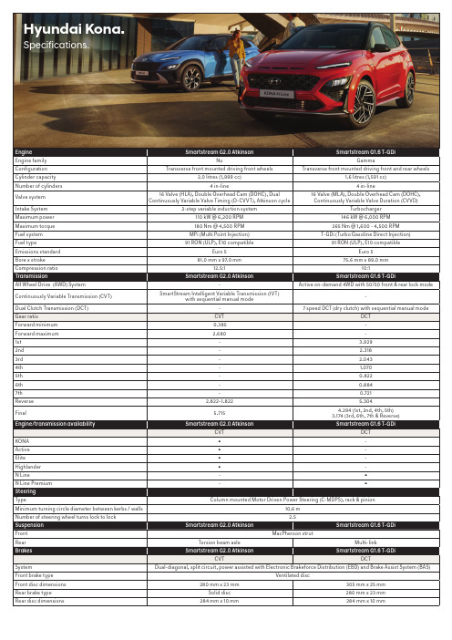
Hyundai Kona. Specifications.Weight Smartstream G2.0 Atkinson Smartstream G1.6 T-GDiCVT DCTKerb weight - lightest 1280 kg1395 kgKerb weight - heaviest1383 kg1504 kgGross Vehicle Mass (GVM)1835 kg1935 kgPermissible Axle Weight (PAW) - front1055 kg1055 kgPermissible Axle Weight (PAW) - rear935 kg960 kgRoof rack load limit80 kg80 kgTowing capacity wing capacity Smartstrea Smartstream G2.0 Atkinson m G2.0 Atkinson Smartstream Smartstream G1.6 T-GDi G1.6 T-GDiCVT DCTBraked1300 kg1250 kgUnbraked600 kg600 kgMaximum towball weight130 kg130 kgFuel consumption*sumption*Smartstre Smartstream G2.0 Atkinson am G2.0 Atkinson Smartstream G Smartstream G1.6 T-GDi 1.6 T-GDiCVT DCTCombined (L/100km) 6.2 6.9Urban (L/100km)8.38.2Extra Urban (L/100km) 5.0 6.1CO2- combined (g/km)148156Fuel tank volume50 L*Source: Australian Design Rule 81/02 static laboratory combined average city and highway cycle test. Real world fuel consumption will vary depending on a combination of driving habits, the condition of the vehicle, and other factors such as road, traffic and weather conditions. ADR 81/02 test results are meant for comparison purposes only.Dimensions KONA Active Elite Highlander N Line N Line Premium ExteriorLength4205 mm4215 mmWidth1800 mmHeight (with roof rails)1550 mm (1565 mm)1560 mm (1575 mm) Wheelbase2600 mmWheel track - front / rear1575 mm / 1584 mm1563 mm / 1572 mm1563 mm / 1572 mm1559 mm / 1568 mm1559 mm / 1568 mm Minimum ground clearance(based on kerb weight) 170mm177mm177mm178mm178mmApproach / departure / ramp break over angle14.8º / 30.7º / 16.1º15.5º / 29.9º / 16.8ºInteriorHead room front / rear (w/ Sunroof)1005 (965) / 961 mmLeg room front / rear1054 / 893 mmShoulder room front / rear1409 / 1385 mmHip room front / rear1355 / 1326 mmCargo area - VDA (minimum / maximum)374 L / 1156 LWheels & tyres KONA Active Elite Highlander N Line N Line Premium Wheel type Alloy Alloy Alloy Alloy Alloy (N Line)Alloy (N Line) Wheel dimensions16 x 6.5J +4417 x 7.0J +5017 x 7.0J +5018 x 7.5J +5218 x 7.5J +5218 x 7.5J +52 Tyre dimensions205/60 R16 92H215/55 R17 94V215/55 R17 94V235/45 R18 94V235/45 R18 94V235/45 R18 94VTyre brand---ContinentalPremiumContact 6ContinentalPremiumContact 6ContinentalPremiumContact 6Spare wheel type Temporary spacesaver Temporary spacesaverTemporary spacesaverTemporary spacesaverTemporary spacesaverTemporary spacesaverDriving convenience KONA Active Elite Highlander N Line N Line Premium Electronic Parking Brake (EPB)(with auto hold function)●●●●●●One touch turn signal - 3, 5, or 7 flashes●●●●●●Rain sensing wipers--●●●●Rear wiper - 2-stage, with auto wipe on reverse ●●●●●●Remote start - via Smart Key--●●●●Smart Key with push button start--●●●●Steering wheel mounted controls - audio,phone, cruise control & trip computer●●●●●●Tilt & telescopic steering column●●●●●●Driving engagement KONA Active Elite Highlander N Line N Line Premium Drive Mode - 4 settings(Eco, Comfort/Normal, Sport, Smart)●●●●●●Traction Mode - 3 settings (Snow, Mud, Sand)●●●●--Active safety KONA Active Elite Highlander N Line N Line Premium Electronic Stability Control (ESC) including;Anti-lock Braking System (ABS)●●●●●●Brake Assist System (BAS)●●●●●●Electronic Brakeforce Distribution (EBD)●●●●●●Downhill Brake Control (DBC)●●●●●●Hill-start Assist Control (HAC)●●●●●●Traction Control System (TCS)●●●●●●Vehicle Stability Management (VSM) ●●●●●●Active safety KONA Active Elite Highlander N Line N Line Premium Hyundai SmartSense ™ including;Blind-Spot Collision-Avoidance Assist (BCA)--●●●●Driver Attention Warning (DAW)●●●●●●Forward Collision-Avoidance Assist (FCA)- camera and radar type, including:●●●●●●- Car/Pedestrian/Cyclist detection- City/Urban/Interurban operational speedsHigh Beam Assist (HBA)---●-●Lane Following Assist (LFA)●●●●●●Lane Keeping Assist - Line/Road-edge(LKA-L/R)●●●●●●Rear Cross-Traffic Collision-AvoidanceAssist (RCCA)--●●●●Rear Occupant Alert (ROA)●●●●●●Safe Exit Warning (SEW)--●●●●Smart Cruise Control with Stop & Go(SCC w/ S&G)●●●●●●Other featuresEmergency Stop Signal (ESS)●●●●●●Parking Distance Warning-Front (PDW-F)- 4 sensors, with guidance display---●-●Parking Distance Warning-Reverse (PDW-R)- 4 sensors, with guidance display-●●●●●Rear view camera with dynamic guide lines●●----Rear View Monitor with Parking Guidance(RVM w/ PG)--●●●●Tyre Pressure Monitoring System (TPMS) -individual tyre pressure readout●●●●●●Passive safety KONA Active Elite Highlander N Line N Line Premium AirbagsFront airbags - driver & front passenger●●●●●●Side (thorax) airbags - driver & front passenger●●●●●●Side curtain airbags - 1st & 2nd row●●●●●●Roll-over Sensor●●●●●●DoorsImpact sensing auto door unlock●●●●●●Rear door child safety locks●●●●●●SeatbeltsPretensioners, load limiters & heightadjustable upper mounts on front seat belts●●●●●●Pretensioners & load limiters on rear seat belts●●●●●●Seat belt reminder - front & rear seatbelts●●●●●●SeatingHeight adjustable front head restraints withtilt function●●●●●●Height adjustable rear head restraints●●●●●●ISOFIX child restraint anchors(rear outboard seats)●●●●●●Top tether child restraint anchors (rear)- 3 anchors●●●●●●Security KONA Active Elite Highlander N Line N Line Premium Security systemActive lock/unlock operation(user configurable)●●●●●●Anti-theft alarm●●●●●●Central locking●●●●●●Engine immobiliser●●●●●●RemotesKeyless entry remote - 2x●●----Smart Key remote - 2x--●●●●Multimedia system KONA Active Elite Highlander N Line N Line Premium FunctionsApple CarPlay1 & Android Auto2 compatibility●●●●●●Bluetooth phone connectivity●●●●●●Satellite navigation --●●●●Live traffic updates (RDS-TMC)--●●●●Touch screen - 8” display●●----Touch screen - 10.25” display--●●●●Multimedia system KONA Active Elite Highlander N Line N Line Premium SpeakersAudio system - 6 speakers●●----Harman Kardon™ premium audio system- 8 speakers with external amplifier--●●●●Audio/media sourcesAM/FM radio●●●●●●Digital radio (DAB+)--●●●●Radio Data System (RDS)●●●●●●USB multimedia input●●●●●●Bluetooth audio streaming●●●●●●Quiet Mode - Speaker volume limitation fora quieter cabin●●●●●●Occupant comfort & convenience KONA Active Elite Highlander N Line N Line Premium Upholstery/trimLeather3 appointed interior - seats, steeringwheel & gear knob-●●●●●Front seatsDriver’s seat - height adjustable●●●●●●Driver’s seat - power adjustable - 10-way(including 2-way lumbar support) ---●-●Passenger’s seat - height adjustable●●●●●●Passenger’s seat - power adjustable - 8-way---●-●Front centre console storage cubby - poweroutlets - 2 x 12V outlets●●●●●●Front centre console - wireless charging pad(Qi standard)4●●●●●●Grip handles - 1x (passenger)●●●●●●Rear seatsCentre fold down armrest-●●●●●Grip handles - 2x●●●●●●Rear centre console - USB power outlet●●●●●●Windows/shadesAcoustic laminated windshield glass--●●●●Glass sunroof - tilt and slide panel ---●5-●5One touch window up & down function withanti-pinching safety feature - driver’s window●●●●●●Power windows - front & rear●●●●●●Rear privacy glass-●●●●●Solar control glass -●●●●●Sunvisor (extendable) - driver and frontpassenger●●●●●●Vision & sight KONA Active Elite Highlander N Line N Line Premium Interior mirrorElectro-chromatic Mirror (ECM)- auto-dimming---●-●Exterior mirrorsHeated-●●●●●Power adjustable ●●●●●●Power folding with auto fold function-●●●●●Instrument cluster/driving displaysHead-Up Display (HUD)---●-●Supervision cluster - 4.2” TFT colour LCDwith trip computer & digital speedometer●●●-●-Supervision cluster - 10.25” TFT colour LCDwith trip computer & digital speedometer---●-●Ventilation & heating KONA Active Elite Highlander N Line N Line Premium Air conditioningClimate control - single zone with auto defogfunction--●●●●Manual controls●●----Cabin air filter ●●●●●●Cooling/heating vents - rear floor●●●●●●Front seatsAir ventilated front seats---●-●Heated front seats---●-●Ventilation & heating KONA Active Elite Highlander N Line N Line Premium Rear seatsHeated rear outboard seats---●-●Other featuresHeated rear windshield●●●●●●Heated steering wheel---●-●Exterior styling KONA Active Elite Highlander N Line N Line Premium FrontFront bumper garnish insert - satin chrome--●●--Front bumper garnish insert - silver●●----Front grille lower - gloss black●●●●--Front grille upper - black●●----Front grille upper - gloss black--●●--Front skid plate - silver--●●--Front skid plate - grey●●----N Line-exclusive front bumper----●●N Line-exclusive mesh design grille----●●SideBody cladding - body colour----●●Body cladding - carbon grey--●●--Side garnish insert - silver--●●--N Line-exclusive side skirts----●●RearDual exhaust tips - chrome ----●●Skid plate - grey●●----Skid plate - silver--●●--Spoiler - roof colour matched, tailgatemounted ●●●●●●Tailgate garnish insert - chrome--●●--N Line-exclusive rear bumper----●●N Line-exclusive rear diffuser----●●Interior styling KONA Active Elite Highlander N Line N Line Premium TreatmentsBlack headlining----●●Cloth headlining---●5-●5 Charcoal grey inserts (interior door handles,steering wheel and air vents)----●●Coloured inserts, stitching & piping - red----●●(air vents, gear knob, gear shift boot, seatsand steering wheel)MaterialsPremium materials - door centre trim-●●●●●Sports pedals - alloy----●●DesignN Line-exclusive sports gear knob----●●N Line-exclusive sports front seats----●●N Line-exclusive sports steering wheel----●●Lighting KONA Active Elite Highlander N Line N Line Premium Exterior lighting - frontFog lights--●●--Daytime Running Lights (DRL) - LED●●●●●●Headlight functions - automatic dusksensing with escort and welcome●●●●●●Headlight type - LED (low/high beam)---●-●Headlight type - multi face reflector---●-●Headlight type - projector beam●●●-●-Indicator lights - LED---●-●Positioning lights - LED●●●●●●Exterior lighting - rearFog light●●●●●●High Mount Stop Light (HMSL) - LED●●●●●●Rear combination lights - LED (bulbreverse lights)---●-●Lighting KONA Active Elite Highlander N Line N Line Premium Exterior lighting - othersSide repeaters - LED, integratedinto side mirrors●●●●●●Interior lighting - frontFront ambient lighting - LED, in centreconsole cup holders and lower legroom---●-●Front room lights and map lights●●●●●●Glovebox compartment light●●●●●●Vanity mirror lights ●●●●●●Interior lighting - rearCentre room light●●●●●●Interior lighting - othersCargo area light●●●●●●Interior light fade-out delay●●●●●●Storage solutions KONA Active Elite Highlander N Line N Line Premium Front seatsCup holders - centre console ●●●●●●Front seat back pockets-●●●●●Glovebox compartment●●●●●●Retractable sunglasses compartment●●●●●●Ticket holders - sunvisors(driver and front passenger)●●●●●●Rear seatsCoat hooks - 1x●●●●●●Cup holders - armrest-●●●●●Rear seating split folding - 60:40●●●●●●Boot/Luggage areaBag hooks - 1x●●●●●●Cargo shelf●●●●●●Luggage compartment - 4x mounting points●●●●●●Luggage net ●●●●●●Side storage recess - right side●●----OthersDoors - map pockets and bottle bulges(front and rear)●●●●●●Roof Rails●●●●●●Option packages KONA Active Elite Highlander N Line N Line Premium Two-Tone Roof packPhantom Black two-tone roof and sidemirrors---○-○Notes:1. Apple CarPlay requires iPhone 5 or subsequent model (lightning cable) in order to operate.2. Android Auto requires a device with Android 5.0 operating system or subsequent version in order to operate.3. Finishes specified as leather may contain elements of genuine leather, polyurethane leather (leather substitute) or man-made materials, or a combination thereof.4. Wireless charging requires a Qi-enabled smartphone or adapter in order to operate.5. Feature not available when Two-tone roof is optioned.Key:● = Feature is available on trim○ = Feature is available on trim only as part of an option pack- = Feature is not available on trim。
Eaton Moeller series Rapid Link速控器198910产品说明说明书

Eaton 198910Eaton Moeller® series Rapid Link - Speed controllers, 5.6 A, 2.2 kW, Sensor input 4, Actuator output 2, 230/277 V AC, Ethernet IP, HAN Q4/2, with manual override switch, STO (Safe Torque Off)Allgemeine spezifikationEaton Moeller® series Rapid Link Speed controller198910157 mm270 mm 220 mm 3.6 kgCE RoHS UL approval UL 61800-5-1 IEC/EN 61800-5-14015081969685RASP5-5422EIP-412R010S1Product NameCatalog NumberProduct Length/Depth Product Height Product Width Product Weight Certifications Catalog Notes EANModel Code3 fixed speeds and 1 potentiometer speedcan be switched over from U/f to (vector) speed control Connection of supply voltage via adapter cable on round or flexible busbar junctionParameterization: drivesConnectParameterization: FieldbusParameterization: KeypadParameterization: drivesConnect mobile (App)Manual override switchControl unitKey switch position AUTOKey switch position OFF/RESETKey switch position HANDPC connectionTwo sensor inputs through M12 sockets (max. 150 mA) for quick stop and interlocked manual operationSelector switch (Positions: REV - OFF - FWD)Thermo-click with safe isolationIGBT inverter2 Actuator outputsInternal DC linkPTC thermistor monitoring3 fixed speedsSTO (Safe Torque Off)For actuation of motors with mechanical brake1 potentiometer speed IP65NEMA 121st and 2nd environments (according to EN 61800-3)IIISpeed controllerEtherNet/IPC1: for conducted emissions onlyC2, C3: depending on the motor cable length, the connected load, and ambient conditions. External radio interference suppression filters (optional) may be necessary.2000 VPhase-earthed AC supply systems are not permitted.AC voltageCenter-point earthed star network (TN-S network)Vertical15 g, Mechanical, According to IEC/EN 60068-2-27, 11 ms, Half-sinusoidal shock 11 ms, 1000 shocks per shaftResistance: 6 Hz, Amplitude 0.15 mmResistance: According to IEC/EN 60068-2-6Resistance: 57 Hz, Amplitude transition frequency on accelerationResistance: 10 - 150 Hz, Oscillation frequency Above 1000 m with 1 % performance reduction per 100 m Max. 2000 m-10 °C40 °C-40 °C70 °CFeatures Fitted with:Functions Degree of protectionElectromagnetic compatibility Overvoltage categoryProduct categoryProtocolRadio interference classRated impulse withstand voltage (Uimp) System configuration typeMounting position Shock resistance Vibration AltitudeAmbient operating temperature - min Ambient operating temperature - max Ambient storage temperature - min Ambient storage temperature - max Climatic proofing< 95 %, no condensationIn accordance with IEC/EN 50178Current limitationAdjustable, motor, main circuit0.5 - 5.6 A, motor, main circuitDelay time< 10 ms, On-delay< 10 ms, Off-delayEfficiency98 % (η)Input current ILN at 150% overload5.3 ALeakage current at ground IPE - max3.5 mAMains current distortion120 %Mains switch-on frequencyMaximum of one time every 60 secondsMains voltage - min380 VMains voltage - max480 VMains voltage tolerance380 - 480 V (-10 %/+10 %, at 50/60 Hz)Operating modeSynchronous reluctance motorsBLDC motorsPM and LSPM motorsSensorless vector control (SLV)U/f controlOutput frequency - min0 HzOutput frequency - max500 HzOverload currentFor 60 s every 600 sAt 40 °COverload current IL at 150% overload8.4 A45 Hz66 Hz5.6 A at 150% overload (at an operating frequency of 8 kHz and an ambient air temperature of +40 °C)2.2 kW480 V AC, 3-phase400 V AC, 3-phase0.1 Hz (Frequency resolution, setpoint value)200 %, IH, max. starting current (High Overload), For 2 seconds every 20 seconds, Power section50/60 Hz8 kHz, 4 - 32 kHz adjustable, fPWM, Power section, Main circuitPhase-earthed AC supply systems are not permitted.AC voltageCenter-point earthed star network (TN-S network)3 HP≤ 0.6 A (max. 6 A for 120 ms), Actuator for external motor brake≤ 30 % (I/Ie)Adjustable to 100 % (I/Ie), DC - Main circuit230/277 V AC -15 % / +10 %, Actuator for external motor brake10 kAType 1 coordination via the power bus' feeder unit, Main circuit230/277 V AC (external brake 50/60 Hz)24 V DC (-15 %/+20 %, external via AS-Interface® plug)Ethernet IP, built inPlug type: HAN Q4/2Number of slave addresses: 31 (AS-Interface®)Max. total power consumption from AS-Interface® power supply unit (30 V): 250 mASpecification: S-7.4 (AS-Interface®)C2 ≤ 5 m, maximum motor cable length C1 ≤ 1 m, maximum motor cable length C3 ≤ 25 m, maximum motor cable lengthMeets the product standard's requirements.Rated frequency - minRated frequency - maxRated operational current (Ie)Rated operational power at 380/400 V, 50 Hz, 3-phase Rated operational voltageResolutionStarting current - maxSupply frequencySwitching frequencySystem configuration type Assigned motor power at 460/480 V, 60 Hz, 3-phase Braking currentBraking torqueBraking voltageRated conditional short-circuit current (Iq)Short-circuit protection (external output circuits) Rated control voltage (Uc)Communication interfaceConnectionInterfacesCable length10.2.2 Corrosion resistanceMeets the product standard's requirements.Meets the product standard's requirements.Meets the product standard's requirements.Meets the product standard's requirements.Does not apply, since the entire switchgear needs to be evaluated.Does not apply, since the entire switchgear needs to be evaluated.Meets the product standard's requirements.Does not apply, since the entire switchgear needs to be evaluated.Meets the product standard's requirements.Does not apply, since the entire switchgear needs to be evaluated.Does not apply, since the entire switchgear needs to be evaluated.Is the panel builder's responsibility.Is the panel builder's responsibility.Is the panel builder's responsibility.Is the panel builder's responsibility.Is the panel builder's responsibility.Elektromagnetische Verträglichkeit (EMV) Generationenwechsel RA-SP zu RASP5Generationentausch RA-SP zu RASP4.0Generation change from RA-MO to RAMO 4.0Configuration to Rockwell PLC for Rapid Link Generationentausch RA-MO zu RAMO4.0Configuration to Rockwell PLC Rapid Link 5Generation change RAMO4 to RAMO5Generation Change RA-SP to RASP5Generation change from RA-SP to RASP 4.0Anschluss von Frequenzumrichtern an Generatornetze Generationentausch RAMO4 zu RAMO5Generation Change RASP4 to RASP5Firmware Update RASP 4.0Generationswechsel RASP4 zu RASP5MN034004_DEMN040003_DERapid Link 5 - brochureDA-SW-drivesConnect - installation helpDA-SW-Driver DX-CBL-PC-3M0DA-SW-USB Driver DX-COM-STICK3-KITDA-SW-drivesConnect - InstallationshilfeDA-SW-USB Driver PC Cable DX-CBL-PC-1M5DA-SW-drivesConnectMaterial handling applications - airports, warehouses and intra-logistics ETN.RASP5-5422EIP-412R010S1.edzIL034093ZUDE | Rapid Link 5Sortimentskatalog Antriebstechnik-DE10.2.3.1 Verification of thermal stability of enclosures10.2.3.2 Verification of resistance of insulating materials to normal heat10.2.3.3 Resist. of insul. mat. to abnormal heat/fire by internal elect. effects10.2.4 Resistance to ultra-violet (UV) radiation10.2.5 Lifting10.2.6 Mechanical impact10.2.7 Inscriptions10.3 Degree of protection of assemblies10.4 Clearances and creepage distances10.5 Protection against electric shock10.6 Incorporation of switching devices and components10.7 Internal electrical circuits and connections10.8 Connections for external conductors10.9.2 Power-frequency electric strength10.9.3 Impulse withstand voltage10.9.4 Testing of enclosures made of insulating material Anmerkungen zur AnwendungBenutzerhandbücherBroschüreneCAD model Installationsanleitung InstallationsvideosKatalogeEaton Konzern plc Eaton-Haus30 Pembroke-Straße Dublin 4, Irland © 2023 Eaton. Alle Rechte vorbehalten. Eaton ist eine eingetrageneMarke.Alle anderen Warenzeichen sindEigentum ihrer jeweiligenBesitzer./socialmediaThe panel builder is responsible for the temperature rise calculation. Eaton will provide heat dissipation data for the devices.Is the panel builder's responsibility. The specifications for the switchgear must be observed.Is the panel builder's responsibility. The specifications for the switchgear must be observed.The device meets the requirements, provided the information in the instruction leaflet (IL) is observed.ramo5_v33.dwgrasp5_v33.stpeaton-bus-adapter-rapidlink-speed-controller-dimensions-005.eps eaton-bus-adapter-rapidlink-speed-controller-dimensions-002.eps eaton-bus-adapter-rapidlink-speed-controller-dimensions-004.eps eaton-bus-adapter-rapidlink-speed-controller-dimensions-003.eps10.10 Temperature rise10.11 Short-circuit rating10.12 Electromagnetic compatibility 10.13 Mechanical function mCAD model Zeichnungen。
- 1、下载文档前请自行甄别文档内容的完整性,平台不提供额外的编辑、内容补充、找答案等附加服务。
- 2、"仅部分预览"的文档,不可在线预览部分如存在完整性等问题,可反馈申请退款(可完整预览的文档不适用该条件!)。
- 3、如文档侵犯您的权益,请联系客服反馈,我们会尽快为您处理(人工客服工作时间:9:00-18:30)。
2
第一章 概述
安全 安全总则 通过本手册,重要的安全注意事项有以下几点
警告
表示存在危险,提请用户对操作步骤、实际操作、实际条件等类事项加以注意, 如不正确执行或切实遵守,则有可能会导致人身伤害甚至死亡。
小心
表示存在危险,提请用户对操作步骤、实际操作、实际条件等类事项加以注意,
如不正确执行或切实遵守,则有可能会导致本产品部分或者全部发生损坏甚至损 毁。
注意 对重要信息进行强调。提请用户对必要的操作步骤、实际操作、
实际条件等类事项加以注意。
和产品有关安全警事项 您手中的Model 2061烟气湿度仪已由工厂进行安全测试和审核。请注意以下几点
警告 将机器接地,定期检查装置避免被雷击。
小心 不要修改计量单位,不当修改会损坏机器导致故障。
防静电保护 静电放电会直接或间接损坏电子电路。本公司的产品有充分的防静电措施。但在 触摸/移动设备内部电路或在设备内部接入其他设备时时,仍有可能产生静电损 害。 为了防止高压静电损害: —请在防静电工作台以及合理接地的情况下,处理静电敏感元件。
第二章 概述........................................................5 部件说明................................................... 6
第三章 安装........................................................7
7
电缆接线 配套使用带屏蔽的4芯电缆作为模拟输出/串口通讯电缆。电缆的定义与号码管的 对应如下:
220V-PE = 地 220V-L = 220VAC火线 220V-N = 220VAC零线 H2O(4-20mA+) =烟气湿度H2O输出信号的电缆+ H2O(4-20mA-) = 烟气湿度H2O输出信号的电缆-
4
第二章 概述
高温烟气一般指火电行业燃煤发电工程产生的气体,作为一种比较特殊的介 质,一般的温度范围在40-150度,特别情况下可能达到160度,另外烟气中一般 会存在粉尘和酸性物质如SO2、NOX等,如何克服高温、高粉尘和酸性物质而保证 烟气水分的在线测量,是一个十分困难的问题,目前在国内一般通过测量干湿烟 气中的氧量,通过计算获得烟气水分,是一种间接测量的方法,这种方法存在的 主要问题是测量值滞后而测量的精度低,不能满足高温烟气测量的需要。
从低湿到高湿环境:10S
湿度传感器:
阻容式
温度传感器:
PT100 铂电阻
输出信号:
4…20mA
供电电源:
24VDC
模拟输出外接负载:
最大 500Ω(对地)
电流消耗:
最大 2 A
功耗(最大):
25W
工作温度范围:
传感器:
-40…+180°C
变送器及控制部分:
-10…+55°C
储存温度:
-40…+80°C
减震材料以保护设备。请将报告一并放到箱中。 6. 将箱子寄到:
3
—如果上述情况不可能,在接触电路板前应释放身上静电。操作者应佩戴防静电 手腕和阻性接线塞绳。 —若上述情况不可能,应一只手接触导电体,另一只手触摸电路板。 —尽量把持电路板边缘,避免与元器件的直接接触。 环保
循环使用可再生材料。
根据当地法令处理废旧电池和仪表。不要和家庭垃圾一并处 理。
反馈 雪迪龙公司欢迎我们的用户对我们说明书的质量提出宝贵的意见和建议。如
第六章 校准和调校 校准.......................................................14
第七章 技术规范.................................................15 性能 ......................................................15 技术支持...................................................16 返修说明...................................................16
5
部件说明
图1 湿度仪结构示意图 数字对应上面的图1: 1 =加热线样气进口:Φ6mm,卡套式接头。 2 =烟气湿度仪(变送器、信号模块和加热部分等) 3 =样气出口: Φ6mm,卡套式接头。 4=加热指示灯 5=RS232接口
6
湿度仪安装示意图如图2,
第三章 安装
图2 湿度仪安装示意图 数字对应上图2 1 =加热线 2 =样气进口:Φ6mm,卡套式接头 3 =样气出口: Φ6mm,卡套式接头。 4 =供电电源线 5 =输出信号线 6=加热指示灯 7=RS232接口
操作手册
Model 2061 烟气湿度仪
北京雪迪龙自动控制系统有限公司
2009-1-12
未经版权持有人的事先书面许可,不得以任何形式或者任何手段,无论是电子的还是机械的 (其中包括影印),对本手册任何部分进行复制,也不得将其内容传达给第三方。 本说明手册内容如有变更,恕不另行通知。 需要注意的是此操作手册对客户并没有法律效力,双方的权利义务由双方的合同和销售当时 的情况而定。
针对上述现有技术的不足,Model 2061烟气湿度仪采用一种能克服高温烟气 的粉尘、高温和酸性腐蚀问题、可以在线长期稳定的测量高温烟气中水分的防磨 损和防腐蚀装置,以有效保护在线阻容式高温烟气水分仪,并在不影响测量精度 的条件下实现长期可靠的工作。
本操作手册介绍了关于雪迪龙公司Model 2061系列烟气湿度仪的安装、操作、 和维修。 Model 2061烟气湿度仪的测量范围是0-40Vol%。
果您发现了错误或是由其他改进的意见,请注明章节,段落,和页数。 许可证协议
雪迪龙公司和第三方拥有软件的所有权,用户只有在签订了合同或软件使用 许可证后方可使用。 质保
雪迪龙公司对本产品有为期一年的质保。质保不包括正常的磨损,非正常情 况的操作,安装和操作的疏忽,或是未经授权的改动。请注意供应合同或销售合 同关于每台机器质保的细节
常见的水分测量方法有:冷凝法,干湿球法,称重法,露点法和电子式传感 器法。电子式水分传感器产品及水分测量属于90年代兴起的行业,近年来,国内 外在水分传感器研发领域取得了长足进步,气体水分的测量在国外目前的发展方 向主要是利用电容式电子测量技术,但应用于高温烟气的测量,需要克服烟气高 温、灰尘、酸性物质对高分子薄膜电容的磨损和腐蚀问题。
服务端口的串口通信设置默认值
参数
值
波特率
2400
奇偶校验
无
数据位
8
停止位
1
流控制
无
用串口命令调校PPMV
1.至少要在5小时内保持传感器稳定。
2.将串口波特率调至2400bit
3. 等至少 1 个小时。
modi PPMV xx
用串口命令modi PPMV xx进行PPMV的调校。
用modi PPMV xx 命令进行调校。用 modi PPMV ? 查询修正PPMV
9
安装开孔尺寸图
10
第四章 操作
本章包括了操作该产品所需信息。 开始
Model 2061水分仪的启动时间总共大概20分钟。在 Model 2061上电后自动 进入启动预热状态,过完成后, 进入测量状态,输出数据正式启动。
11
串口通信
使用服务端口连接串口进行的RS-232连接。服务端口工作于固定的串口设置。
1
目
录
第一章 概述...................................................... 3 安全....................................................... 3 安全总则................................................... 3 和产品有关的安全注意事项................................... 3 防静电保护................................................. 3 环保........................................................4 反馈........................................................4 商标........................................................4 许可证协议................................................ 4 质保....................................................... 4
工作环境湿度:
0…100%RH
设备全重:
<1 Kg
15
技术支持 技术问题,请与技术部联系: E-mail Fax
返修说明 如果产品需要维修,请遵循以下说明以加快进程,避免额外成本。 1. 阅读质保信息。 2. 填写问题报告,并附上能对所述问题提供更多建议的技术人员的姓名和联
系方式。 3. 报告上请说明: -什么问题(什么工作/什么不工作)? -哪里出现的问题(位置和环境)? -什么时候出现的问题(日期,当时/不久前/周期性的/随意的) -多少问题(一个/其他或类似的/一个个体内的几个错误)? 4. 报告上要有详细寄信人地址,首选的运输方式。 5. 将问题设备装好,放到一个适合的结实的箱子中,要在箱子里填充缓冲及
例如:
>modi PPMV 0.5
OK
此时PPMV已经修正0.5%,可以用查询命令查看修正值。