技鼎CP7-level3
VS-3手工工具套餐说明书

VS-3Hand Tool Kits1of 6Jan 2017 Rev E244271-1,244271-5,and 244271-6PROPER USE GUIDELINESWire Figure1VS-3Hand Tool Kit 244271-1and -5with Hand Tool Assembly 230971-1VS-3Hand Tool Kit 244271-61.INTRODUCTIONVS--3Hand Tool Kit 244271--1includes a standard VS--3hand tool assembly,crimp height gage,black nylon cord,repair tag,and a carrying case.Hand Tool Kit 244271--5includes everything in the --1kit plus a tool holder assembly.Hand Tool Kit 244271--6includes everything in the --1kit except the standard hand tool assembly is replaced with Hand Tool Assembly 230971--5.The hand tool is designed to join cable conductors (wires)using PICABOND ®connectors (standard)listed in Figure 2.Read these instructions thoroughly before crimping any connectors.The tool can be hand held or used in Tool Holder 229755--1.Refer to instruction sheet 408--7655packaged with the tool holder for operating procedure.on this sheet are in metricits [with U .S.customary un its in brackets].Figures are no t drawn to scale.Reasons for reissue are provided in Section 11,REVISION SUMMARY.2.DESCRIPTION (Figure 1)The features of the hand tool and their functions are as follows:Movable die (anvil)and two fixed dies (crimpers)—crimp the connectors.Wire supports—position and hold the wires in the crimpers.Wire cutter—performs two functions.First,it locates the connector on the anvil,and second,it cuts excess wire during the crimp cycle.Movable handle (with quick take--up lever and ratchet)—pushes connector into crimping dies and ensures a highly uniform,finished connection every crimp cycle.engaged,the ratchet will not release until moving handle has been fully closed.Fixed handle—provides support during crimp cycle and,when applicable,can be held securely in tool holder.Cumulative Trauma Disorders can result from the prolonged use of manually powered hand tools. Hand tools are intended for occasional use and lowvolume applications. CommScope offers a wide selection of powered application equipment for extended--use, production operations.Instruction Sheet408-7280patents or their foreign equivalents. For patents, seeColor--Coded Color--Coded StripeColor--Coded StripeCONNECTORDESCRIPTIONPART NUMBERCOLOR--CODED STRIPE28--24Regular 61899--1Orange Regular60945--4Green Weather Resistant61226--2Purple Regular Load Coil 552576--226--22Breakaway Load Coil 552647--2Weather Resistant Load Coil552639--2Weather Resistant Breakaway Load Coil552769--2Regular60947--3Red 24--19Weather Resistant61292--2YellowUse any one or two wire combination.Use only one wire size 19AWG in combination with any other wire up to size 24AWG per connector end.Figure 23.CABLE PREPARATIONThe recommended cable may include size 28through 19AWG copper conductors that are insulated with plastic (PIC),ribbon--paper,or pulp materials.Open and prepare the cable in the usual manner.There is no special procedure required when using the VS--3hand tool.4.CONNECTOR SELECTIONDetermine the size and combination of wires to be crimped.Then,refer to the chart in Figure 2and select the applicable connector.Note that the PICABOND connectors (standard)have a color--coded stripe for easy identification.5.WIRE PLACEMENTThe difference between splicing,bridging,and tapping applications is the placement of the wires in the wire supports.Determine the type of connection to be made,then refer to the applicable paragraph (5.1,5.2,or 5.3)and insert the wires accordingly.5.1.In-Line Splicing (Figure 3)Always start with the cable units to the REAR of the cable opening.1.Take a pair (tip and ring)of wires from one side of the cable opening and separate them far enough that one wire can be inserted into the wire support.ce the wire into the wire support above the pin and out between the crimpers.Make sure the wire has sufficient slack,then bottom it in the wire support.3.Repeat steps one and two using a pair of wires from the other side of the cable opening.Be sure to match tip to tip or ring to ring.4.Insert the connector into the tool,making sure the wire cutter enters the slots in the middle of the connector.Crimp the connector according to Section 6.5.2.Bridging (Figure 4)ce the bridge wire(s)into the wire support(s)BELOW the pin(s)and out between the crimpers.2.Take a pair (tip and ring)of wires from one side of the cable opening and separate them far enough that one wire can be inserted into the wire support.ce the wire into the wire support above the pin and out between the crimpers.4.Repeat Steps 2and 3using a pair of wires from the other side of the cable opening.5.Make sure all wires have sufficient slack,then bottom them in the wire supports.Insert theconnector into the tool,making sure the wire cutter enters the slots in the middle of the connector.Crimp the connector according to Section 6.When butt splicing,insert one wire above the pin and one wire below the pin on the same side of the tool.Regular ConnectorWeather Resistant ConnectorLoad Coil ConnectorStripeWIRE SIZE RANGE(AWG)Green/AmberPurple/AmberFigure3In--Line SpliceSlack In WireWire CutterPinFigure4Slack in In--Line WireWire Bridge WireWire SupportConnectorPinSingle Bridge Double Bridge Butt SpliceIn--Line 5.3.Tapping (Figure 5)The tapping connection is accomplished without cutting and interrupting service of the in--line ce the tap wire(s)into the wire support(s)below the pin(s)and out between the crimpers.2.Place the in--line wire into the connector.Insert the connector and in--line wire into the tool,making sure the wire cutter enters the slots in the middle of the connector.Position the in--line wire in the notch of the wire cutter,then lace it into the wire supports above the pins.3.Make sure all wires have sufficient slack,then bottom them in the wire supports.Crimp the connector according to Section 6.Figure5Slack WireIn--Line WirePinWire SupportTap WireConnectorWire CutterNotchSingle Half--Tap Double Half--Tap6.CRIMPING PROCEDUREAfter placing the wires and the connector in the tool,crimp the connector as follows:There must be sufficient slack in the wires,andthe tool must be held steady during the crimping procedure.Otherwise,the wires could pull out of the connector during the crimp cycle.1.To hold the tool steady,grasp the front portion of the fixed handle with one hand and use the other hand to close the quick take--up lever and moving handle.See Figure 6.CAUTIONFigure 62.Squeeze the tool handles together until theratchet releases.Then,allow the handles to open freely and fully.3.Remove the crimped connector from the tool. 7.SPLICE BUILD-UPDuring the splicing,you should arrange groups of finished connectors along the splice opening in order to build a uniform,compact splice.To do this,move the tool along the splice opening about31.75mm [1.25in.]after crimping every25to50pairs,or as local practice dictates.Alternate the direction in which the tool is moved,first to one side of center,then to the other.8.CRIMP INSPECTIONMake the following inspections on the first—and again on the last—connection made during a shift,or as local practice dictates.8.1.Gaging Crimped Connectos (Figure7)Use the crimp height gage(supplied with the tool) immediately after crimping the connection,and check the connector for the following.1.Select the proper gage end by matching thecolor dot on the gage with the color strip on theconnector.2.Place the connector into the gage so the seamin the connector aligns with the double rib on thegage.Position the connector so that one end isflush with the side of the gage.3.Hold the free end of the connector and slide thegage off using only very slight force.The gagemust slide off easily.If it does,repeat the test for the other end of the connector.4.If either end of the connector sticks in the gage,the connection is improperly crimped.Make a few sample crimps and gage them.If they do notengage properly,return the tool for repair.In either case,go back and re--crimp any improperlycrimped connections.Figure7Crimp HeightOrangeGreen orDotWire SizeRangeRed orYellow DotDouble RibSeam8.2.Visual Inspection (Figure8)1.Check for wire protruding from the center of theconnector.If you find any,replace the connection.If this problem occurs frequently,return the tool for adjustment.2.Make certain there are no wires missing fromthe connector.If there is,the tool probably moved during crimping and the connector must bereplaced.3.Check for a metal leg protruding from the centerof the connector.This is caused by improperlocation of the connector in the tool.If you find any, replace the connections.Be especially careful toinsert the connector in the tool so that the slot inthe connector engages the wire cutter,and that the notch in the wire cutter,does not interfere with the connector.See Figures3,4,and5.4.If you are tapping or bridging,make sure theend of the connector with two conductors contains one conductor on each side of the seam.Cycling Tool408-7280Figure 8Protruding Two Wires on Same Side of SeamMissing WiresImproper Connector PlacementIf both conductors are on the same side,replace the connection.Be very careful to place the conductors in the wire support correctly.If the condition persists,return the tool to your supervisor.5.Check the plastic wire support brackets.If they are damaged,or if the pins in the supports are bent or have a rough surface,replace the e Wire Support Replacement Kit 229188--1and follow the instructions in the kit.9.MAINTENANCE AND INSPECTION 9.1.InspectionThe tools are inspected before shipment,and should be inspected immediately upon arrival at your facility to be sure tools have not been damaged in transit.A record of scheduled inspections should remain with each tool and/or be supplied to the personnelresponsible for the tool.Though recommendations call for at least one inspection a month,the frequency should be based on:Care,amount of use,and handling of tool.Degree of operator training and skill.Ambient working conditions (abnormal amounts of dust,dirt,and temperature changes will necessitate more frequent inspections).Your established company standards.9.2.General CleaningClean and lubricate the tool at the beginning of each shift,or as local practice e a telephone company--approved solvent cleaner or equivalent,and a commercially available lubricant,such as WD--40™.Also available is Cleaning Kit 229333--1which consists of a bristle brush for general purpose cleaning,a tube cleaner for cleaning the crimping dies,and a tube brush for cleaning inside the tool.9.3.Clearing Jammed ToolIf tool becomes jammed due to a misplaced connector,complete the cycle and replace thedamaged connector.If you are sure the jam is due to a hard metallic object lodged in the crimpers,return the tool to your supervisor.10.REVISION SUMMARYRevisions to this instruction sheet include:Visual Inspection•Rebranded to CommScope408-7280Weight:.45kg [1lb]50.8mm [2.0in.]4255REPLACEMENT PARTSQUANTITY PER HAND TOOL KIT 244271--1244271--5244271--61230971--1Hand Tool Assembly 11——2229230--1Crimp Height Gage Assembly 111391334--1Carrying Case 1114229755--1Tool Holder Assembly ——1——5229188--1Wire Support Replacement Kit Not Included with Kit (Reference Only)6230971--5Hand Tool Assembly————1Figure 9ITEM PART NUMBER DESCRIPTION。
汇顶 测试工具使用说明书

量产测试工具使用说明文档版本修改说明修改日期V0.1初建2011-5-9 V0.2更新2011-6-3 V0.3更新2011-7-1 V0.4完善参数配置说明2011-8-8 V1.0完善文档2012-3-20 V1.1增加9系说明2012-12-12 V1.2修改自动配屏说明2013-01-17 V1.3增加自动配置测试参数说明2014-02-10深圳市汇顶科技有限公司Copyright©2012GoodIX Tech Co.,Ltd.All rights reserved.目录1测试系统简介 (3)1.1测试环境要求 (3)1.2DBG-03测试板 (3)1.3悬浮测试板 (5)2功能介绍 (7)2.1主界面及使用 (7)2.2数据(TP)分析 (9)2.3导入\导出配置 (12)2.4测试系统基本设置 (12)2.5测试板固件升级功能 (13)2.5.1升级步骤 (13)2.5.2注意事项 (14)2.6GT芯片升级功能 (14)2.7调试配置参数 (15)2.8设定芯片配置参数 (15)2.9手动设定测试参数 (17)2.9.1手动设定节点测试参数 (18)2.9.2手动获取&设定测试参数 (18)3调试配置参数 (20)3.1参数手动微调 (20)3.2参数自动配置 (20)3.3自动获取&设定测试参数 (22)4测试说明 (23)4.1模组测试 (23)4.1.1I2C接口 (23)4.1.2USB接口方案 (24)4.2Sensor测试 (24)4.2.1基于GT9的Sensor测试 (25)4.2.2基于GT818Sensor Daughter Board (27)4.3COF\FPC测试 (27)4.4测试结果 (30)4.5NG分析 (31)4.5.1NG产生的原因 (31)4.5.2NG分析步骤 (32)4.5.3调整测试参数 (35)5INI文件说明 (36)5.1生成Ini文件 (36)5.2产线模式设置 (36)6常见问题及处理方法 (38)1测试系统简介量产测试系统(GuitarTestPlatform)包含测试板以及运行于Windows的软件,分别为:DBG-03测试板,Daughter Board,以及GuitarTestPlatform(GTP)软件,GTP软件支持所有芯片的测试。
长盛 CS2676CX、CS9901 系列测试仪使用说明书
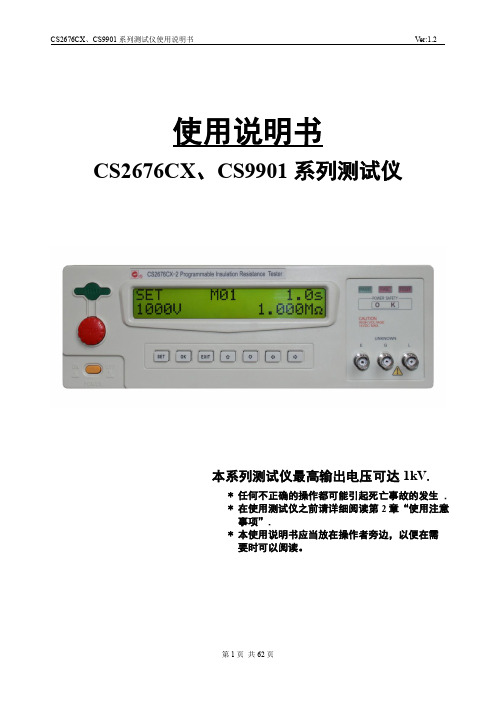
使用说明书CS2676CX、CS9901系列测试仪本系列测试仪最高输出电压可达1kV.* 任何不正确的操作都可能引起死亡事故的发生 . * 在使用测试仪之前请详细阅读第2章“使用注意事项”.* 本使用说明书应当放在操作者旁边,以便在需要时可以阅读。
CS2676CX、CS9901系列测试仪使用说明书V er:1.2 说明书的使用说明:* 在操作测试仪前请仔细阅读并理解说明书所描述的内容。
阅读后,请把说明书放在操作人员附近以便在需要时进行阅读。
当把测试仪从一个工作场所搬运到另外一个工作场所,请把说明书随仪器仪器搬运,以免遗失。
* 如果发现说明书缺页或者说明书被污染,请立即与长盛公司的经销商联系进行购买。
* 随着仪器功能的改进、软件的升级,使用说明书也将不断被完善、升级。
请注意测试仪器的软件和说明书的版本。
版本修改记录:日期修改内容版本号2010.10 开始编写初稿 1.02011.01 增加CS9901系列充电电流说明 1.12011.03 增加通信说用说明和通信协议 1.2* 在测试过程中,操作人员请不要触摸以下所述的位置或区域;否则会造成触电事故的发生。
(1)测试仪的高压输出端口;(2)与测试仪连接的测试线的鳄鱼夹;(3)被测试产品;(4)和测试仪输出端连接的任何物体;* 为防止触电事故的发生,请遵循下面的安全操作步骤:(1)为了预防触电事故的发生,在使用测试仪进行操作前,请先戴上绝缘的橡皮手套再从事与本测试仪有关的工作。
(2)安全可靠的接地:本系列测试仪的后面板上有一接地端子,请将此端子接地。
如果没有可靠的接地,当电源与机壳短路时或者在测试过程中,高压测试线与机壳短路时,机壳都会有高压的存在,这是非常危险的。
只要任何人接触外壳,都有可能造成触电的发生,因此必须将此接地端子可靠的与大地连接。
(3)在测试仪的电源开关打开后,请不要触摸和高压输出端口有连接的任何物品;(4)在更换保险丝时,请务必把电源插头拔掉。
JMGPM 25 M9BW 30 通用接线器型号说明文档说明书

JMGPM 25M9BW30Port thread typeNil M thread ø12 to ø32Rc ø40 to ø100TN NPT TFGTypeSpecial functionElectrical entryI n d i c a t o r l i g h tWiring (Output)Load voltage Auto switch model Lead wire length [m]Pre-wiredconnector Applicable load DCACPerpendicularIn-line0.5(Nil)1(M)3(L)5(Z)S o l i d s t a t e a u t o s w i t c h———Grommet Yes 3-wire (NPN)24 V5 V, 12 V —M9NV M9N V V V v v IC circuit Relay, PLC3-wire (PNP)M9PV M9P V V V v v 2-wire12 V M9BV M9B V V V v v —Diagnostic indication (2-color indicator)3-wire (NPN)5 V, 12 V M9NWV M9NW V V V v v IC circuit 3-wire (PNP)M9PWV M9PW V V V v v 2-wire 12 V M9BWV M9BW V V V v v —Water resistant (2-color indicator)3-wire (NPN) 5 V, 12 V M9NAV ∗∗M9NA ∗∗v v V v v IC circuit 3-wire (PNP)M9PAV ∗∗M9PA ∗∗v v V v v 2-wire12 VM9BAV ∗∗M9BA ∗∗vvVvv—Applicable Auto Switches /Refer to the WEB catalog or Best Pneumatics for further information on auto switches.∗ Lead wire length symbols: 0.5 m………… N il (Example) M9NW 1 m………… M (Example) M9NWM 3 m………… L (Example) M9NWL 5 m………… Z (Example) M9NWZ∗ For details about auto switches with pre-wired connector, refer to the WEB catalog or Best Pneumatics.∗ Auto switches are shipped together, (but not assembled).∗ Solid state auto switches marked with “v ” are produced upon receipt of order.∗∗ Water resistant type auto switches can be mounted on the above models, but in such case SMC cannot guarantee water resistance.Please contact SMC regarding water resistant types with the above model numbers.How to OrderCylinder stroke [mm]Refer to “Standard Strokes” on page 4.Bearing type MSlide bearingBore size1210 mm x 21612 mm x 22016 mm x 22520 mm x 23225 mm x 24032 mm x 25040 mm x 26345 mm x 28056 mm x 210071 mm x 2Auto switchNilWithout auto switch (Built-in magnet)∗ For applicable auto switches, refer to the table below.Number of auto switchesNil 2S 1nnCompactGuide CylinderJMGP Seriesø12, ø16, ø20, ø25, ø32, ø40, ø50, ø63, ø80, ø1003Standard StrokesOUTIN[N]Bore size [mm]Rod size [mm]Operating directionPiston area[mm 2]Operating pressure [MPa]0.20.30.40.50.60.7ø12(ø10 x 2)6OUT 1573147637994110IN 101203040506070ø16(ø12 x 2)6OUT 226456890113136158IN 17034516885102119ø20(ø16 x 2)8OUT 40280121161201241281IN 3026090121151181211ø25(ø20 x 2)10OUT 628126188251314377440IN 47194141188236283330ø32(ø25 x 2)12OUT 982196295393491589687IN 756151227302378453529ø40(ø32 x 2)16OUT 16083224836438049651126IN 1206241362483603724844ø50(ø40 x 2)18OUT 25135037541005125715081759IN 2004401601802100212031403ø63(ø45 x 2)20OUT 31816369541272159019092227IN 25535117661021127615321787ø80(ø56 x 2)25OUT 492698514781970246329563448IN 394478911831578197223672761ø100(ø71 x 2)30OUT 7918158423763167395947515543IN 6505130119512602325239034553Note) Theoretical output [N] = Pressure [MPa] x Piston area [mm 2]Theoretical OutputSpecificationsBore size [mm]Standard stroke [mm]ø12 (ø10 x 2)ø16 (ø12 x 2)10, 20, 30, 50, 100ø20 (ø16 x 2)ø25 (ø20 x 2)20, 30, 50, 100, 150ø32 (ø25 x 2)ø40 (ø32 x 2)ø50 (ø40 x 2)ø63 (ø45 x 2)ø80 (ø56 x 2)ø100 (ø71 x 2)25, 50, 100, 150, 200∗ Intermediate strokes are available as a special order.Bore size [mm]ø12(ø10 x 2)ø16(ø12 x 2)ø20(ø16 x 2)ø25(ø20 x 2)ø32(ø25 x 2)ø40(ø32 x 2)ø50(ø40 x 2)ø63(ø45 x 2)ø80(ø56 x 2)ø100(ø71 x 2)Action Double actingFluidAir Proof pressure1.05 MPa Maximum operating pressure 0.7 MPa ∗1Minimum operating pressure 0.15 MPa Ambient and fluid temperature 5 to 60°CPiston speed Note)∗50 to 300 mm/s ∗150 to 250 mm/s ∗1Cushion Rubber bumper on both ends LubricationNot required (Non-lube)Stroke length tolerance+1.50mmNote) Maximum speed with no load∗ Depending on the system configuration selected, the specified speed may not be satisfied.∗1 Maximum operating pressure and piston speed are different from the current product (MGP series).[kg]Bore size [mm]Stroke [mm]1020253050100150200ø12 (ø10 x 2)0.090.12—0.140.190.30——ø16 (ø12 x 2)0.100.13—0.150.200.32——ø20 (ø16 x 2)—0.21—0.250.330.530.72—ø25 (ø20 x 2)—0.28—0.330.430.680.92—ø32 (ø25 x 2)——0.60—0.77 1.11 1.44 1.78ø40 (ø32 x 2)——0.80— 1.07 1.62 2.16 2.70ø50 (ø40 x 2)—— 1.27— 1.63 2.36 3.09 3.82ø63 (ø45 x 2)—— 1.60— 2.03 2.89 3.74 4.60ø80 (ø56 x 2)—— 2.81— 3.47 4.79 6.127.44ø100 (ø71 x 2)——4.48— 5.407.229.0510.87WeightSymbolRubber bumperRefer to pages 10 and 11 for cylinders with auto switches.·Auto switch proper mounting position (detection at stroke end) and mounting height·Minimum stroke for auto switch mounting ·Operating range·Auto switch mounting4Compact Guide CylinderJMGP Series。
SENTRON 3LD 三极切换器手动操作说明书

3
3LD2064-0TB51-0US2 Page 3/9
03/10/2020
Subject to change without notice © Copyright Siemens
Hasp thickness / of the bracket locks / minimum Hasp thickness / of the bracket locks / maximum
2.5 kA2.s
100 000 50 1/h
690 V 6 kV 16 A
690 V
IP65 IP65
0.5 W
0.5 W
9A 16 A 16 A 16 A 16 A 16 A 16 A 16 A 16 A 16 A
16 A 16 A 16 A 16 A 16 A 20 A
3 kA
3LD2064-0TB51-0US2 Page 2/9
Protection class Protection class IP Protection class IP / on the front
Dissipation Power loss [W] ● for rated value of the current / at AC / in hot operating state / per pole ● per conductor / typical
03/10/2020
Subject to change without notice © Copyright Siemens
● at 690 V / for combination switch + gG fuse / maximum permissible Short-time withstand current (Icw) ● limited to 1 s / rated value ● at 690 V / limited to 1 s / rated value
禾川 X3E 系列伺服驱动器 用户手册说明书

2021年10月V5.2手册号:HPPD0120000承蒙购买本产品,在此深表谢意001001002005007009009010012012016017017020021026027028028028031038040040041前言1.关于使用说明书2.开箱时的确认事项3.安全注意事项第一章 产品说明及系统选型1.1 铭牌与型号介绍(电机和驱动器) 1.2 伺服电机及驱动器各部名称 1.3 伺服驱动器与电机机种名称对应表 1.4 外围制动电阻选型1.5 外围电缆及连接器配件选型第二章 产品规格2.1 伺服驱动器规格2.1.1 基本规格 2.1.2 过负载检出特性 2.2 伺服电机规格2.2.1 基本规格2.2.2 输出轴的容许负载 2.2.3 N -T特性图 2.2.4 编码器规格 2.2.5 关于油封第三章 伺服电机及驱动器安装与尺寸 3.1 安装环境条件 3.2 防尘・防水 3.3 安装方法与空间 3.4 伺服电机外型尺寸 3.5 伺服驱动器外型尺寸第四章 伺服电机及驱动器配线说明 4.1 系统配线图4.1.1 系统配线图4.1.2 伺服电机及驱动器连接器说明0420420450450470490500520600610640640650660690720740740780810840900900941004.2 驱动器连接器及插针排列说明 4.2.1 驱动器连接器端子说明 4.3 电机连接器端子排列与配线色别4.3.1 电机连接器和插针排列(750W以下) 4.3.2 电机连接器和插针排列(1kW以上) 4.4 RS-485通讯配线说明4.5 用户控制端子(CN 1)配线说明 4.6 用户I/O连接器(CN 1)的配线 4.7 系统时序图4.7.1 接通电源时(接收伺服使能信号的时序) 4.7.2 电机旋转时的伺服使能开启、关闭动作4.7.3 异常(故障)发生时(伺服使能开启指令状态) 4.7.4 报警清除时(伺服使能开启指令状态)第五章 面板显示及操作5.1 按键说明 5.2 显示说明5.3 按键操作点动(JOG)和参数辨识 5.3.1 按键点动(JOG)时的操作及显示5.3.2 按键惯量辨识和编码器初始角辨识时的操作及显示第六章 控制功能6.1 位置控制模式 6.2 速度控制模式 6.3 转矩控制模式 6.4 运动控制功能 6.4.1 内部位置指令 6.4.2 抢断定位 6.4.3 原点回归第七章 参数7.1 参数一览表 7.2 参数详细说明参数详细说明——P00组 基本设置参数详细说明——P01组 增益调整参数详细说明——P02组 振动抑制058058058059059第十章 通信10.1 通信读写参数的规则 10.2 通信读写命令195195137149153157159167169171171173173176176178178178179179182182184186186187188参数详细说明——P08组 内部位置指令参数详细说明——P09组 通信设定参数详细说明——P18组 电机型号参数详细说明——P20组 键盘和通信操控接口参数详细说明——P21组 状态参数 数字输入(DI)功能定义表数字输出(DO)功能定义表第八章 调整 8.1 增益调整 8.1.1 总体说明 8.2 自动增益调整 8.2.1 功能说明 8.3 自适应滤波器 8.3.1 功能说明 8.4 手动增益调整 8.4.1 总体说明 8.4.2 位置模式的调整 8.4.3 速度模式的调整 8.4.4 增益切换功能 8.4.5 前馈功能 8.4.6 机械共振抑制 8.4.7 低频振动抑制 8.5 负载参数自学习 8.5.1 惯量辨识第九章 故障保护和报警 9.1 报警代码一览表 9.2 报警原因及处理措施104110120125132参数详细说明——P03组 速度转矩控制参数详细说明——P04组 数字输入输出参数详细说明——P05组 模拟输入输出参数详细说明——P06组 扩展参数参数详细说明——P07组 辅助功能参数详细说明——P17组扩展位置控制功能156第十章 通信10.3 通信控制 DI 功能 10.4 通信读取 DO 功能 10.5 读取编码器绝对值位置版本信息197199200感谢您使用本产品,本操作手册提供SV-X3E系列驱动器及电机相关信息。
ICOP技术股份有限公司的VDX3-ETX用户手册说明书
VDX DM&P1GH VDX3-ETXwithDM&P Vortex86DX31GHz processorVersion 6.0X3CopyrightThe information in this manual is subject to change without notice for continues improvement in the product. All rights are reserved. The manufacturer assumers no reasonability for any inaccuracies that may be contained in this document and makes no commitment to update or to keep current the information contained in this manual.No part of this manual may be reproduced, copied, translated or transmitted, in whole or in part, in any form or by any means without the prior to written permission of ICOP Technology Inc.ⓒCopyright 2016 ICOP Technology IncTrademarks Acknowledgement Vortex86DX3TM is the registered trademark of DM&P Electronics Inc. Other brand names and product names that appear in this document are the properties and registered trademarks of their respective owners. All names mentioned herewith are served for identification purpose only.Revision HistoryTable of Contents1 General Information (5)1.1 Overview (5)1.2 Block diagram (6)1.3 Specifications (7)1.4 Ordering Information (8)2 Hardware Information (10)2.1 Board Dimension (10)2.2 Dimension with heatsink/heatspreader (12)2.3 Connector and Jumper Location (14)2.4 Connector and Jumper Summary (15)2.5 Pin Assignments & Jumper Settings (15)J1: JTAG (15)J2&J6: SATA DOM (15)J3: SATA DOM Power (16)J4: LVDS Switch (16)J5: Giga Ethernet (16)X1: PCI, USB & Audio (17)X2: ISA (19)X3: VGA, LVDS, COM x2, PS/2 and Printer(Optional) (21)X4: IDE, Ethernet, Power and others (23)2.6 System Mapping (25)3 Software Resources (28)3.1 ICOP Technical Resource Website (28)4 Basic BIOS Setting (29)4.1 Introduction (29)4.2 IDE Configuration (29)4.3 Advanced PCI-PnP Setting (30)4.4 ACPI Enable (30)5 Basic LCD Panel Setting (31)5.1 Introduction (31)5.2 Pin Assignment of LVDS (31)5.3 Basic BIOS Setting for LCD (32)Technical Support Directly from ICOP (34)User Manual Feedback (34)Appendix (35)Warranty (36)1 General Information1.1OverviewThe VDX3-ETX is a low-power CPU module which compliant with ETX standard. It takes the advantage of Vortex86DX3 1GHz x86 CPU which integrate the PCIe, IDE, I2C, VGA, LVDS, PS/2, USB, HD Audio and even with 16-bit ISA bus support.The VDX3-ETX is designed as a plug in replacement, with backward compatibility to support legacy software to help extend existing product life cycle without heavy re-engineering.1.2Block diagram1.3Specifications1.4Ordering Informationrequired, please contact ICOP (*************.tw).**24-bit Signal channel LVDS running with VDX3-ETX module as default. If 24-bit Dual channel LVDS is required, please contact ICOP (*************.tw).Heatsink (For detail, please see Chapter 2.3):Accessories:2 Hardware Information 2.1Board DimensionTop ViewBottom View2.2 Dimension with heatsink/heatspreaderWith heatsink (item number: Heatsink-ETX-D3T)With heatspreader (item number: Heatspreader-ETX-D3T)2.3Connector andTop ViewBottom ViewJ6J5J3X2X1r and Jumper LocationJ2J1X4X32.4Connector and Jumper Summary2.5Pin Assignments & Jumper Settings J1: JTAGFor ICOP use only.J2&J6: SATA DOMJ6 is an optional SATA DOM horizontal connector.J3: SATA DOM PowerJ4: LVDS Switch18-Bit LVDS Support 24-Bit LVDS SupportJ5: Giga EthernetX1: PCI, USB & AudioPin Signal Voltage 5V I/O tolerant Pin Signal Voltage 5V I/O Tolerant A1 GND - - A2 GND - - A3 PCICLK2 VCC3 - A4 PCICLK3 VCC3 - A5 GND - - A6 GND - - A7 PCICLK0 VCC3 - A8 PCICLK1 VCC3 - A9 REQ3# VCC3 - A10 GNT3# VCC3 -A11 GNT2# VCC3 - A12 3V - -A13 REQ2# VCC3 - A14 GNT1# VCC3 -A15 REQ1# VCC3 - A16 3V - -A17 GNT0# VCC3 - A18 RESERVED - -A19 VCC - - A20 VCC - -A21 Not supported - - A22 REQ0# VCC3 -A23 AD0 VCC3 - A24 3V - -A25 AD1 VCC3 - A26 AD2 VCC3 -A27 AD4 VCC3 - A28 AD3 VCC3 -A29 AD6 VCC3 - A30 AD5 VCC3 -A31 CBE0# VCC3 - A32 AD7 VCC3 -A33 AD8 VCC3 - A34 AD9 VCC3 -A35 GND - - A36 GND - -A37 AD10 VCC3 - A38 AUXAL VCC -A39 AD11 VCC3 - A40 MIC VCC -A41 AD12 VCC3 - A42 AUXAR VCC -A43 AD13 VCC3 - A44 ASVCC VCC -A45 AD14 VCC3 - A46 SNDL VCC -A47 AD15 VCC3 - A48 ASGND .- -A49 CBE1# VCC3 - A50 SNDR VCC -Pin Signal Voltage 5V I/O tolerant Pin Signal Voltage 5V I/O Tolerant A51 VCC - - A52 VCC - -A53 PAR VCC3 - A54 SERR# VCC3 -A55 GPERR# VCC3 - A56 RESERVED - -A57 PME# VCC3 - A58 USB2- VCC3 -A59 LOCK# VCC3 - A60 DEVSEL# VCC3 -A61 TRDY# VCC3 - A62 USB3- VCC3 -A63 IRDY# VCC3 - A64 STOP# VCC3 -A65 FRAME# VCC3 - A66 USB2+ VCC3 -A67 GND - - A68 GND - -A69 AD16 VCC3 - A70 CBE2# VCC3 -A71 AD17 VCC3 - A72 USB3+ VCC3 -A73 AD19 VCC3 - A74 AD18 VCC3 -A75 AD20 VCC3 - A76 USB0- VCC3 -A77 AD22 VCC3 - A78 AD21 VCC3 -A79 AD23 VCC3 - A80 USB1- VCC3 -A81 AD24 VCC3 - A82 CBE3# VCC3 -A83 VCC - - A84 VCC - -A85 AD25 VCC3 - A86 AD26 VCC3 -A87 AD28 VCC3 - A88 USB0+ VCC3 -A89 AD27 VCC3 - A90 AD29 VCC3 -A91 AD30 VCC3 - A92 USB1+ VCC3 -A93 PCIRST# VCC3 - A94 AD31 VCC3 -A95 INTC# VCC3 - A96 INTD# VCC3 -A97 INTA# VCC3 - A98 INTB# VCC3 -A99 GND - - A100 GND - -X2: ISAPin Signal Voltage 5V I/O tolerant Pin Signal Voltage 5V I/O Tolerant B1 GND - - B2 GND - - B3 SD14 VCC B4 SD15 VCCB5 SD13 VCC B6 MASTER# - - B7 SD12 VCC B8 DREQ7 VCCB9 SD11 VCC B10 DACK7# VCC3 YB11 SD10 VCC B12 DREQ6 VCCB13 SD9 VCC B14 DACK6# VCC3 YB15 SD8 VCC B16 DREQ5 VCCB17 MEMW# VCC B18 DACK5# VCC3 YB19 MEMR# VCC B20 DREQ0 VCCB21 LA17 VCC B22 DACK0# VCC3 YB23 LA18 VCC B24 IRQ14 VCCB25 LA19 VCC B26 IRQ15 VCCB27 LA20 VCC B28 IRQ12 VCCB29 LA21 VCC B30 IRQ11 VCCB31 LA22 VCC B32 IRQ10 VCCB33 LA23 VCC B34 IOCS16# VCCB35 GND - B36 GND - -B37 SBHE# VCC3 Y B38 MEMCS16# VCCB39 SA0 VCC B40 OSC VCCB41 SA1 VCC B42 BALE VCC3 YB43 SA2 VCC B44 TC VCC3 YB45 SA3 VCC B46 DACK2 # VCC3 YB47 SA4 VCC B48 IRQ3 VCCB49 SA5 VCC B50 IRQ4 VCCPin Signal Voltage 5V I/O tolerant Pin Signal Voltage 5V I/O Tolerant B51 VCC - - B52 VCC - -B53 SA6 VCC B54 IRQ5 VCCB55 SA7 VCC B56 IRQ6 VCCB57 SA8 VCC B58 IRQ7 VCCB59 SA9 VCC B60 SYSCLK VCCB61 SA10 VCC B62 REFSH# VCC3 YB63 SA11 VCC B64 DREQ1 VCCB65 SA12 VCC B66 DACK1# VCC3 YB67 GND - - B68 GND - -B69 SA13 VCC B70 DREQ3 VCCB71 SA14 VCC B72 DACK3# VCC3 YB73 SA15 VCC B74 IOR# VCCB75 SA16 VCC B76 IOW# VCCB77 SA18 VCC B78 SA17 VCCB79 SA19 VCC B80 SMEMR# VCCB81 IOCHRDY VCC B82 AEN VCC3 YB83 VCC - - B84 VCC - -B85 SD0 VCC B86 SMEMW# VCCB87 SD2 VCC B88 SD1 VCCB89 SD3 VCC B90 OWS# VCC3 YB91 DREQ2 VCC B92 SD4 VCCB93 SD5 VCC B94 IRQ9 VCCB95 SD6 VCC B96 SD7 VCCB97 IOCHK# VCC B98 RSTDRV VCC3 YB99 GND - - B100 GND - -X3: VGA, LVDS, COM x2, PS/2 and Printer(Optional)Pin Signal Voltage 5V I/O tolerant Pin Signal Voltage 5V I/O Tolerant C1 GND - - C2 GND - - C3 R - - C4 B - - C5 HSY VCC - C6 G - - C7 VSY VCC - C8 DDCK VCC3 - C9 DETECT# VCC3 - C10 DDDA VCC3 -C11 TXLCK1- VCC1.8 - C12 TXOUT13- VCC1.8 -C13 TXLCK1+ VCC1.8 - C14 TXOUT13+ VCC1.8 -C15 GND - - C16 GND - -C17 TXOUT11+ VCC1.8 - C18 TXOUT12+ VCC1.8 -C19 TXOUT11- VCC1.8 - C20 TXOUT12- VCC1.8 -C21 GND - - C22 GND - -C23 TXOUT3- VCC1.8 - C24 TXOUT10+ VCC1.8 -C25 TXOUT3+ VCC1.8 - C26 TXOUT10- VCC1.8 -C27 GND - - C28 GND - -C29 TXOUT2- VCC1.8 - C30 TXLCK+ VCC1.8 -C31 TXOUT2+ VCC1.8 - C32 TXLCK- VCC1.8 -C33 GND - - C34 GND - -C35 TXOUT0+ VCC1.8 - C36 TXOUT1+ VCC1.8 -C37 TXOUT0- VCC1.8 - C38 TXOUT- VCC1.8 -C39 VCC - - C40 VCC - -C41 Not supported - - C42 Not supported - -C43 Not supported - - C44 BLON# - -C45 BIASON - - C46 DIGON# - -C47 COMP VCC3 - C48 Y VCC3 -C49 Not supported - - C50 C VCC3 -:First Channel LVDS:Second Channel LVDSPin Signal Voltage 5V I/O tolerant Pin Signal Voltage 5V I/O Tolerant C51 LPT VCC3 Y C52 Not supported - -C53 VCC - - C54 GND - -C55 STB# VCC3 - C56 AFD# VCC3 -C57 Not supported - - C58 PD7 VCC3 YC59 Not supported C60 ERR# VCC3 YC61 Not supported C62 PD6 VCC3 YC63 RXD2 VCC3 Y C64 INT# VCC3 -C65 GND - - C66 GND - -C67 RTS2# VCC3 - C68 PD5 VCC3 YC69 DTR2# VCC3 - C70 SLIN# VCC3 -C71 DCD2# VCC3 Y C72 PD4 VCC3 YC73 DSR2# VCC3 Y C74 PD3 VCC3 YC75 CTS2# VCC3 Y C76 PD2 VCC3 YC77 TXD2 VCC3 - C78 PD1 VCC3 YC79 RI2# VCC3 Y C80 PD0 VCC3 YC81 VCC - - C82 VCC - -C83 RXD1 VCC3 Y C84 ACK# VCC3 YC85 RTS1# VCC3 - C86 BUSY# VCC3 YC87 DTR1# VCC3 - C88 PE VCC3 YC89 DCD1# VCC3 Y C90 SLCT# VCC3 -C91 DSR1# VCC3 Y C92 MSCLK VCC3 YC93 CTS1# VCC3 Y C94 MSDAT VCC3 YC95 TXD1# VCC3 - C96 KBCLK VCC3 YC97 RI1# VCC3 Y C98 KBDAT VCC3 YC99 GND - - C100 GND - -X4: IDE, Ethernet, Power and othersPin Signal Voltage 5V I/O tolerant Pin Signal Voltage 5V I/O Tolerant D1 GND - - D2 GND - -D3 5V_SB - - D4 PWGIN VCC -D5 PS_ON# VSB5 - D6 SPEAKER VCC3 -D7 PWRBTN# VSB5 - D8 BATT VCC3 -D9 Not supported - - D10 LILED VCC3 -D11 Not supported - - D12 ACTLED VCC3 -D13 Not supported - - D14 Not supported - -D15 Not supported - - D16 I2CLK VCC3 YD17 VCC - - D18 VCC - -D19 Not supported - - D20 GPCS# VCC3 YD21 Not supported - - D22 I2DAT VCC3 YD23 Not supported - - D24 Not supported - -D25 Not supported - - D26 Not supported - -D27 Not supported - - D28 Not supported - -D29 Not supported - - D30 PIDE_CS3# VCC3 YD31 Not supported - - D32 PIDE_CS1# VCC3 YD33 GND - - D34 GND - -D35 Not supported - - D36 PIDE_A2 VCC3 YD37 Not supported - - D38 PIDE_A0 VCC3 YD39 Not supported - - D40 PIDE_A1 VCC3 YD41 Not supported - - D42 Not supportedD43 Not supported - - D44 PIDE_INTRQ VCC3 YD45 Not supported - - D46 PIDE_AK# VCC3 YD47 Not supported - - D48 PIDE_RDY VCC3 YD49 VCC - - D50 VCC - -Pin Signal Voltage 5V I/O tolerant Pin Signal Voltage 5V I/O Tolerant D51 Not supported - - D52 PIDE_IOR# VCC3 YD53 Not supported - - D54 PIDE_IOW# VCC3 YD55 Not supported - - D56 PIDE_DRQ VCC3 YD57 Not supported - - D58 PIDE_D15 VCC3 YD59 Not supported - - D60 PIDE_D0 VCC3 YD61 Not supported - - D62 PIDE_D14 VCC3 YD63 Not supported - - D64 PIDE_D1 VCC3 YD65 GND - - D66 GND - -D67 Not supported - - D68 PIDE_D13 VCC3 YD69 Not supported - - D70 PIDE_D2 VCC3 YD71 Not supported - - D72 PIDE_D12 VCC3 YD73 Not supported - - D74 PIDE_D3 VCC3 YD75 Not supported - - D76 PIDE_D11 VCC3 YD77 Not supported - - D78 PIDE_D4 VCC3 YD79 Not supported - - D80 PIDE_D10 VCC3 YD81 VCC - - D82 VCC - -D83 Not supported - - D84 PIDE_D5 VCC3 YD85 Not supported - - D86 PIDE_D9 VCC3 YD87 Not supported - - D88 PIDE_D6 VCC3 YD89 Not supported - - D90 CBLID_P VCC3 YD91 RXD- VCC3 - D92 PIDE_D8 VCC3 YD93 RXD+ VCC3 - D94 SIDE_D7 VCC3 YD95 TXD- VCC3 - D96 PIDE_D7 VCC3 YD97 TXD+ VCC3 - D98 HDRST# VCC3 YD99 GND - - D100 GND - -2.6System Mapping3 Software Resources3.1ICOP Technical Resource WebsiteIn the following website, you will find our latest user manuals, including OS support resources systems such as evaluation images for Windows Embedded Compact 7, Windows Embedded CE6.0, and Windows XP Embedded (Win XPe), etc. For details, please visit the link below:/4 Basic BIOS Setting4.1IntroductionFeaturing AMI BIOS, the VDX3-ETX module is a one stable module board for your applications. In this section, we will introduce you some basic AMI BIOS setting such as CPU speed adjusting, console redirection, and IDE configuration, etc.4.2IDE ConfigurationThe default IDE configuration is for Windows Operating System, and the setting as below:Onboard IDE Operate Mode: [Legacy Mode]IDE Compatibility:[Disabled].If you would like to use Linux on VDX3-ETX, please follow below instructions:Onboard IDE Operate Mode:[Native Mode]IDE Compatibility:[Enabled].Path of Onboard IDE Operate Mode:Advanced >IDE Configuration >Onboard IDE Operate Mode [Native Mode]4.3Advanced PCI-PnP SettingTwo statuses for IRQ setting:[Reserved]: IRQ will free to be allocated by PnP BIOS.[Available]: IRQ will not free to be allocated by PnP BIOS.Path: PCIPnP >IRQ4.4ACPI EnableTo install Windows 7 on ICOP computer boards, please enable ACPI as the following instruction.Path: Advanced >Power Management Configuration >ACPI Configuration >ACPI Aware O/S5 Basic LCD Panel Setting5.1 IntroductionThe VDX3-ETX offers two different interfaces which support maximum resolution up to 1920 x 1080 (at 60 MHz) connecting to VGA and LCD Flat Panel with 18-bit/24bit LVDS.The default setting of Boot Display Device[VBIOS] and LCD Panel Index[VBIOS] with Clone Display [ENBALED] support dual display (LCD and VGA) on VDX3-ETX.If your VGA display shifts because of the above setting, please switch Boot Display Device[VBIOS] to [CRT] as the following image:**Boot Display Device [VBIOS]: LCD and VGA display supported with display setting basedon your required LCD specification.[CRT]: VGA display supported5.2 Pin Assignment of LVDSPlease refer Page 20 for LVDS pin assignment.5.3 Basic BIOS Setting for LCDIf you would like to use LCD panel with VDX3-ETX, please follow below instruction: Boot Display Device [VBIOS]LCD Panel Index according to your LCD resolution from VBIOS to 5.Path of Boot Display Device setting:Boot >Boot Settings Configuration >Boot Display Device[VBIOS]Path of LCD Panel Index setting:Boot >Boot Settings Configuration >LCD Panel Index [ ]***The [VBIOS] difference between Boot Display Device and LCD Panel Index:Boot Display Device [VBIOS]: Display Output SettingLCD Panel Index [VBIOS]: Display Resolution SettingTechnical Support Directly from ICOP To offer you more accurate and specific solutions for the technical situations you have, please prepare the information below before contacting ICOP:—Product name and serial number—Description of the H/W environment ( i.e.: working temperature, I/O board information, information of connection between main boardand IO boards, and/or other devices, etc)—Description of the S/W environment (i.e: operating system, version,application software, and/or other related information, etc.)—A detailed description and photos of the technical situation—Any complement or technical situations you want ICOP morefocusing onUser Manual FeedbackTo make this user manual more complete, if you have any comments or feedbacks to this manual, please feel free to write to *************.tw or contact your ICOP sales representative.WarrantyThis product is warranted to be in good working order for a period of one year (12 months) from the date of purchase. Should this product fail to be in good working order at any time during this period, we will, at our option, replace or repair it without additional charge except as set forth in the following terms. This warranty does not apply to products damaged by misuse, modifications, accident or disaster. Vendor assumes no liability for any damages, lost profits, lost savings or any other incidental or consequential damage resulting from the use, misuse of, originality to use this product. Vendor will not be liable for any claim made by any other related party. Return authorization must be obtained from the vendor before returned merchandise is accepted. Authorization can be obtained by calling or faxing the vendor and requesting a Return Merchandise Authorization (RMA) number. Returned goods should always be accompanied by a clear problem description. Should you have questions about warranty and RMA service, please contact us directly.ICOP Technology Inc.Address: No. 15 Wugong 5th Road, Xinzhuang Dist.New Taipei City, Taiwan (R.O.C.) 24890TEL: +886-2-8990-1933FAX: +886-2-8990-2045Mail: *************.twWebsite: 。
STPTI-15L2C4 WLCSP 3 金属条 PTIC RF2 RF1 偏置特性说明书
STPTIC-15L2C4WLCSP 3 solder barsPTICRF1Features•High power capability •5:1 tuning range •High linearity (48x)•High quality factor (Q)•Low leakage current•Compatible with high voltage control IC (STHVDAC series)•RF tunable passive implementation in mobile phones to optimize antenna radiated performance•Available in wafer level chip scale package:–WLCSP package 0.75 x 0.72 x 0.32 mm •ECOPACK ®2 compliant componentApplications•Cellular antenna open loop tunable matching network in multi-band GSM/WCDMA/LTE mobile phone •Open loop tunable RF filtersDescriptionThe ST integrated tunable capacitor offers excellent RF performance, low power consumption and high linearity required in adaptive RF tuning applications. Thefundamental building block of PTIC is a tunable material called Parascan™, which is a version of barium strontium titanate (BST) developed by Paratek microwave.BST capacitors are tunable capacitors intended for use in mobile phone application and dedicated to RF tunable applications. These tunable capacitors are controlled through an extended bias voltage ranging from 1 to 24 V. The implementation of BST tunable capacitor in mobile phones enables significant improvement in terms of radiated performance making the performance almost insensitive to the external environment.Parascan is a trademark of Paratek Microwave Inc.Parascan™ tunable integrated capacitorSTPTIC-15C4DatasheetSTPTIC-15C4STPTIC-15C4 characteristics 1STPTIC-15C4 characteristicsTable 1. Absolute maximum ratings (limiting values)1.Class 1B defined as passing 500 V, but fails after exposure to 1000V ESD pulse.Table 2. Recommended operating conditionsTable 3. Representative performance (T amb = 25 °C otherwise specified)1.Measured at low frequency2.F 1 = 894 MHz, F 2 = 849 MHz, P 1 = +25 dBm, P 2 = +25 dBm, 2f 1 - f 2 = 939 MHz3.IP3 and harmonics are measured in the shunt configuration in a 50 Ω environment4.850 MHz, P IN = +34 dBm5.One or both of RF IN and RF OUT must be connected to DC ground, using the HVDAC turbo mode. Transition time for tunerbetween Cmin. to 90% of Cmax. or Cmax. to 90% of Cmin. include MIPI order work time (trig with last MIPI CLK).1.1RF measurementsFigure 3. Harmonic power versus bias voltage (shunt)Figure 4. Harmonic power versus bias voltage (series)STPTIC-15C4RF measurementsFigure 5.Third order intercept point (IP3)STPTIC-15C4RF measurements2Package informationIn order to meet environmental requirements, ST offers these devices in different grades of ECOPACK®packages, depending on their level of environmental compliance. ECOPACK® specifications, grade definitionsand product status are available at: . ECOPACK® is an ST trademark.2.1WLCSP 3 solder bars package informationFigure 8. WLCSP 3 solder bars package outlineBottom view(balls up)Top view(balls down)Side view Table 4. WLCSP 3 solder bars package dimensionsSTPTIC-15C4Package informationSTPTIC-15C4WLCSP 3 solder bars package informationFigure 9. Recommended PCB land pattern for WLCSP 3 solder bars package Copper pads Solder stencilTable 5. Dimensions2.2Packing informationFigure 10. Tape and reel outlineTable 6. Pocket dimensionsFigure 11. MarkingTop view (balls down)Bottom view (balls up)STPTIC-15C4Packing informationSTPTIC-15C4Reflow profileTable 7. Pinout description1.When connected in shunt, please connect RF2 (B2 ball) to GND2.3Reflow profileFigure 12. ST ECOPACK® recommended soldering reflow profile for PCB mountingNote:Minimize air convection currents in the reflow oven to avoid component movement.Table 8. Recommended values for soldering reflow3Evaluation boardFigure 14.Layer 1 and layer 4Figure 15. Layer 2 and layer 3RFinRFoutDC BiasSerie RFinRFoutDC BiasSHUNTSTPTIC-15C4Evaluation board4Ordering informationFigure 16. Ordering information schemeST PTIC - 15 L 2 C4ST MicroelectronicsPTICParascan™ tunableIntegrated capacitorCapacitorvalueLinearityF: Standard (x24)G: Standard (x24)L: High (x48)PackageTuning15 = 1.5 pF27 = 2.7 pF33 = 3.3 pF39 = 3.9 pF47 = 4.7 pF56 = 5.6 pF68 = 6.8 pF82 = 8.2 pFM6 : QFNC5 : WLCSP400 µm coating1 = 4/1 tuning2 = 5/1 tuningProduct familyManufacturer-C4 : WLCSP3 solder barsTable 9. Ordering informationOrdering informationRevision historyTable 10. Document revision historyIMPORTANT NOTICE – PLEASE READ CAREFULLYSTMicroelectronics NV and its subsidiaries (“ST”) reserve the right to make changes, corrections, enhancements, modifications, and improvements to ST products and/or to this document at any time without notice. Purchasers should obtain the latest relevant information on ST products before placing orders. ST products are sold pursuant to ST’s terms and conditions of sale in place at the time of order acknowledgement.Purchasers are solely responsible for the choice, selection, and use of ST products and ST assumes no liability for application assistance or the design of Purchasers’ products.No license, express or implied, to any intellectual property right is granted by ST herein.Resale of ST products with provisions different from the information set forth herein shall void any warranty granted by ST for such product.ST and the ST logo are trademarks of ST. All other product or service names are the property of their respective owners.Information in this document supersedes and replaces information previously supplied in any prior versions of this document.© 2018 STMicroelectronics – All rights reservedSTPTIC-15L2C4。
PTZOptics PT-JOY-G3快速使用指南说明书
PTZOptics PT-JOY-G3Quick Start Setup GuideStep 1- When you first receive your PT-JOY-G3, the first thing you should do is read the included manual.Step 2- Once you have read the manual, you can connect your IP joystick to your network. If you network switch provides PoE power, you should not plug in the included power supply. If the network switch is not capable of supplying PoE power, than you should use the included power supply.Step 3- Please NOTE: DHCP isrequired for initial configuration ofyour joystick. The joystickcontroller is unable to spansubnets; the IP camera andjoystick controller must be in thesame subnet of the LAN (example – 192.168.1.123 & 192.168.1.111 belong to the same subnet; 192.168.1.123 & 192.168.0.125 do not).Step 4- Once the joystick boot up process is complete the LCD Screen will display the controllers current IP address. Please take note of this IP address. If you would like to change the joystick language or set a static IP address for the joystick, please follow the detailed instructions in the user manual.Step 5- The joystick is now ready to add cameras IP addresses. The SET UP button opens a menu on the LCD screen. Press the “ENTER” button to add a camera on setting “01/05” or “Add Camera”. Set a Device ID for the corresponding camera o Input the camera’s IP address into the joystick including the “.” between octets. Example: IP = 192.168.100.88Step 6- Let’s quickly add two cameras to the joystick controller.Step 7- Once the joystick has been configured for each of your cameras you can quickly switch between them using the “CAM 1-6” buttons.Note: If the LCD displays “Equipment offline” for a particular camera, please check if the LAN connection to the camera is live and that the camera is powered on.Note: If the LCD displays “Username or Password Error”, please check that the added device’s user name and password have been added in that device’s configuration.Note: Press the “ESC” key to return to the top LCD menu at any time.Note: The “LINK” LED on rear of keyboard will illuminate green any time a camera is successfully connected to.Step 8- Once connected to our selected camera we can use the joystick controller for intuitive pan, tilt and zoom operation. The PTZ Speed can be adjusted by pressing the “Speed” button. You can manually adjust focus and iris using the “Focus +/-” and “Iris +/-” buttons. When taking manualcontrol of focus and iris you will need to make sure to press the “Manual Exposure” and “Manual Focus” buttons. To return to auto focus and auto exposure simply press these corresponding buttons.Step 9- Finally, there is a new feature on this joystick for Focus Lock. You can use this feature by pressing the “A.Focus Lock” key to lock or “A.Focus Unlock” to unlock focus. W hen the focus is “locked” only manual focus adjustments can be made to the current focus state. Keep in mind that if you save a preset with the camera in a manual focus state and with the focus set manually that the focus state will be saved with the preset.Step 10- Now it is time to setup presets. Once you are connected to your selected camera you can press the “Set” button. Once you are in set mode you can move the camera to a PTZ position, selected the number preset you want and press enter. You can continue to do this with multiple PTZ positions, saving each to their unique preset number. We highly suggest keeping a notebook or laminated piece of paper next to your joystick for reference.TIP:To quickly set a camera preset you can simply hold down anumeric key for 3 seconds. Once the key flashes on the LCD screen you will have successfully set a camera preset.Step 11- To recall presets you can click the “CALL” button. Using the keypad you can select the number you would like and then press enter.TIP: T o quickly recall a saved preset simply tap the numeric key torecall that preset at any time.Step 12- For troubleshooting your joystick please reference our user manual on page 17 which offers solutions to common troubleshooting issues.Enjoy!。
GLD Products Pockey 3 in 1 Table 产品说明书
POCKEY 3 IN 1 GAME TABLEReplacement PartsOrder direct at or call our Customer Service department at(800) 225-75938 am to 4:30 pm Central Standard TimeStaple your receipt here.Important: A copy of your receipt will be needed to activate your warranty (see page16).Congratulations and THANK YOU for purchasing thePockey 3 in 1 Game Table. You have chosen a productthat should provide years of entertainment. To assistyou with customer service and warranty claims,staple your receipt to the inside cover, then keep thismanual in a safe place for future reference.GLD ProductsS84 W19093 Enterprise DriveMuskego, WI 53150 USA1-800-225-7593Fax: 1-800-841-6944Email: **************Web: This manual may have been updated. For the latest manual visit the GLD Products website.Place your package near the location where it will be used. Carefully unpackall components and verify you have all the correct pieces.If you notice missing or defective parts, please call us at:1-800-225-7593Please read and understand all instructions before beginning assembly.This assembly will require 2 adults.This product is not for use by children without adult supervision.Parts Identifier Item 64-1046GLD Products Pockey 3 in 1 Table Parts Identifier Item 64-1046IF YOU HAVE A WARRANTY CLAIM, CALL US FIRST Please see page16.GLD ProductsAvailable 8 am to 4:30 pm Central Standard TimeS84 W19093 Enterprise DriveMuskego, WI 53150 USA1-800-225-7593Fax: 1-800-841-6944Email: **************Web: For all claims, please have your receipt and item number when you call. Theproduct item number can be found on the front cover.If you are instructed to return the product for service, you areresponsible for shipping the unit at your expense.PRODUCT REGISTRATIONImportant: The product registration form on page17 and a copy of yourreceipt must be completed and returned within 10 days of purchase tovalidate your warranty.Online registration is also available. Go to /index.php/registration or click on this link. Follow the online instructions.Preparing for Assembly•Be sure to unpack all of the parts included in this package. Checkinside any tubes or sleeves. Save all packing material until theproduct is fully assembled and functional.•Compare the parts in your package with the Parts Identifierdescription on page4. and 5•After unpacking large products, some disassembly may be requiredprior to beginning the assembly.Tools Required•Allen Wrench (#30)•Open End Wrench (#21)•Box Wrench (#24)•Phillips Screwdriver (not included)•Flat Blade Screwdriver (not included)•Level (not included)•Electric screwdriver may be helpful. CAUTION: You must set atLOW TORQUE and use extreme caution because you couldovertighten the hardware, strip the screws, or damage the table.Assembly TipsMake sure you understand the following before you begin to assemble your game table.1.READ THIS MANUAL all the way through before beginning assembly.2.When installing parts that have more than one bolt, start ALL bolts in that part by handbefore tightening anything.3.Some drawings or images in this manual may not look exactly like your product.4.You may need a second adult to assist with this assembly.Note: Save all packing materials until the parts have been inspected and the table is assembled.Unpack the Pieces•Lay the box on a flat surface (floor). You may want this near yourarea of assembly.•Unpack the boxes and part bags. Inspect and count the parts. TheParts Identifier page can be used to record your results.•If any parts are damaged or missing, contact GLD CustomerService.•Missing fasteners may be purchased at a hardware store using thedescriptions on the Parts Identifier page.GamesThis game table includes the equipment and game pieces for the following games:Air Hockey Pool Table TennisThe rules for these games are not discussed in this manual.STEP 1 - ASSEMBLE THE PEDESTALRemove all components from the carton.NOTE:Parts are packed inside the table top (#1). Remove the pool table surface from the table top (#1) by removing all the screws (#33) that hold it in place. Inside the table top you will find all the parts needed to assemble your table. when all the parts are out of the table top, replace the pool table surface. Reattach the pool table surface by replacing the screws (#33). The assembly parts will include a total of 18 screws (#33). This includes the screws you removed when separating the pool table sur-face from the table top (#1). Be sure to use all 18 screws (#33) when you reattachthe pool table surface to the table top (#1)1.Carefully remove the two (#2) pedestals and four levelers (#22) from the package.2.Insert levelers into pre-drilled holes in the bottom of each leg of the pedestal and securepart way.STEP 2 - ATTACH THE TABLE LOCKSIMPORTANT: The T-nuts are pressed in at the factory. They are on the side of the pedestal that faces the table top (the inside).1.Attach two table locks (#5) to the outside of each pedestal using bolt (#29).STEP 3 - ASSEMBLE THE BASE1.With the help of another person, attach the end rails (#4) to the side rails (#3) using 2" hex bolts (#11), washers (#12), and barrel nuts (#8). Hand tighten bolts.Table top goes on this sideT-nutsTable top onthis sideSTEP 4 - SECURE THE BASE TO THE PEDESTALS1.Insert barrel nuts (#8) into the seven holes in the base.2.Start the four 3" hex head bolts (#10) with 1/4" washers (#12) through the ends of thepedestal and into the side rails. Finger tighten.3.Start the three 2" hex head bolts (#11) with 1/4" washers (#12) through the center of thepedestal and into the end rails. Finger tighten.4.Tighten all bolts using the box wrench (#24).STEP 5 - ATTACH THE TABLE TOPNOTE:The end of the table top with the power cord has the three 3/4" washers (#14) and two 3/4" hex nuts (#15) pre-assembled on the power cord.It is possible that the support axle bolts are not pushed out completely. To pull them out, thread a nut onto the end and pull outward with pliers. If the bolt does not pullout freely, tap it with a hammer to break it loose, then pull.1.Open all four of the table locks.WARNING: Dropping the table or resting all of the table weight on one or two of closed table locks is likely to break the lock mechanism.2.Place one 3/4" washer (#14) over the support axle. Thread the 3/4" hex nut (#15) ontothe axle followed by another washer (#14).3.Lift the table top into position over the side supports.4.Lower the table top so the supporting axles drop into the slots in the pedestals. NOTE:The two washers and the nut should be placed to the inside of the pedestals.5.Place another washer (#14) and thread a nut (#15) onto the support axle.6.Release all of the table locks. Tighten the nuts on the support axle to provide smoothtable top rotation.STEP 6 - ATTACH PUCK CATCHERS AND ACCESSORY HOLDER1.Align the puck catcher (#6) with the pre-drilled holes on each end of the playing table.Secure it to the pedestal with round head screws (#13). Run the power cord through the puck catcher.2.Align the accessory holder (#26) with the pre-drilled holes on each end of the playingtable. Secure it to the pedestal with screws (#13).3.Attach both slide scorers (#31) to the edges of the playing table using four screws (#32).4.The table tennis top is made up of three pieces; two ends (#28) and one middle (#37).Push the three pieces together and use the attached velcro strips to secure them.5.The net (#27) is attached to the middle section (#37).STEP 7 - ADJUST LEVELERS1.With the help of another person, turn each leg leveler until the table rests level to floor.2.Check with a carpenters level placed cross-wise and length-wise on the table top.3.Readjust levelers if necessary.STEP 8 - ASSEMBLE GOALIESRemove backing from felt pads (#9) and place on bottom of goalies (#7).The assembly is complete.To Rotate the Table:CAUTION:This should be performed by an adult. The rotating table may pinch body parts.•Pull out two table locks on one end.•On the other end, pull out the two table locks.WARNING: You must open all four of the table locks. Do not rotate the table with any of the table locks closed. The momentum of the rotating table may break the lock.•Slowly rotate the table.•Push in the table locks.To Level the Table:•Place a carpenters level on the table.•Screw the leg levelers in or out until table is level.Troubleshooting:•If the pool table side is not level, first try to level it by using the leglevelers on each leg. Most of the time the table can be easily leveledusing this method.•If the table surface still needs adjustments, shims may be used onthe cross supports to bring up the low spots. See example below:If the fan does not go on:•Unplug the fan from electrical outlet.•Inspect wiring for proper connection.•Plug in to test.If the fan works but the table has dead spots:•Use a small drill bit and clear the holes by hand. DO NOT useelectric drill. Manually push the drill bit into the holes to clear. Clean the surface by spraying a rag (do not spray directly onto the table top) with a furniture polish (like Pledge) and buffing the surface of the table and the puck. This will provide a bit more “float” which may help prevent getting hung up in the “dead” areas.Care and Use of your Table•This product is intended for INDOOR use only.•DO NOT sit, climb, or lean on the table.•DO NOT drag the table when moving it. This will damage the legs.•Keep your table covered.•To clean the hard surfaces spray a cloth with a mild cleaner andwipe.•Pucks that fly off the table may have chipped edges. Inspect thepuck and replace if needed.90-DAY LIMITED WARRANTYThe Manufacturer warrants to the original retail purchaser that this product is free from defects in material and workmanship under normal use and conditions for a period of ninety (90) days from the date of original purchase. The Manufacturer’s liability is limited to the repair or replacement, at its option, of any defective product and shall not include any liability for indirect, incidental or consequential damages of any kind. Should this product become defective due to material or workmanship within the warranty period, contact our Customer Service Department. This warranty is not transferable and does not cover normal wear and tear or damage caused by improper usage, negligence, misuse, abuse, transportation damage, acts of nature, or accident (including failure to follow the instructions in this manual). It does not cover expendable items such as batteries, light bulbs, fuses, accessories, cosmetic parts and other items that wear out due to normal usage, including felt covered areas of the playing surface. This warranty is also void if the product is disassembled and reassembled, damaged, modified from its original state, or used for other than indoor personal residential use (no commercial or rental applications).This warranty gives you specific legal rights, and you may have other rights which vary from state to state.IF YOU HAVE A WARRANTY CLAIM, CALL US FIRST (8 - 4:30 CST)Please have your receipt and item number (found on the front cover) when you call.GLD ProductsS84 W19093 Enterprise DriveMuskego, WI 53150 USA1-800-225-7593Fax: 1-800-841-6944Email: **************Web: If you are instructed to return the product for service, you are responsible for shipping the unit at your expense to the above address in packaging that will protect against further damage. All warranty or repair requests require a Return Authorization Number prior to returning the item.PRODUCT REGISTRATIONImportant: The product registration form on page17 must be completed and returned along with a copy of your receipt within 10 days of purchase to validate your warranty. Online registration is also available. Go to /index.php/registration or click on this link. Follow the online instructions.REGISTER YOUR PRODUCTPlace postage hereComplete this form, include a copy of your receipt, fold, tape (do not staple) and return within 10 days of purchase. This protects your warranty and will help us develop new products!GLD Products Warranty Department S84 W19093 Enterprise Drive Muskego, WI 53150 USARemember to attach a copy of your receipt.Name Date of Purchase Address Phone-Day City Phone-Evening StateZipEmailPurchase Price:Item: 64-1046 Game TableStore Name:GAME TABLESHOME CASINO GAMES AND ACCESSORIES BILLIARD CUES BILLIARD ACCESSORIES DARTBOARDS SOFT-TIP DARTS STEEL-TIP DARTSFLIGHTS AND SHAFTSDART CASES AND ACCESSORIESFold here second.Fold here first.C u t h e r e .This page left intentionally blank.Pockey 3 in 1 TableItem 64-1046Parts Re-Order FormName DateAddress Phone-Day City Phone-Evening StateZipEmailOrder No.DescriptionUnit Price (each)Qty.Total Amount2-210Table Top 500.002-247Pedestal 50.002-6Side Rail 25.002-8End Rail25.002-209Raised Table Lock 10.002-202Puck Catcher10.002-203Allen Key Bolt 3/16" x 1" 0.252-121/4" Barrel Nut0.252-13Hex Head Bolt 1/4" x 2" 2.002-14Hex Head Bolt 1/4" x 3" 2.002-151/4" Washer 0.252-163/4" Washer 0.202-173/4" Hex Nut 0.202-18Goalie 6.002-19Felt Pad1.002-20Hockey Puck 1.502-21Billiard Balls 30.002-22Brush 8.002-23Cue Stick 12.002-24Chalk2.002-25Open End Wrench 1.002-26Leg Levelers 10.002-27Triangle 6.001-17Box Wrench 1.002-204Cue Rack5.002-205Accessory Holder10.002-311/2" Phillips Head Screw0.202-286Table Tennis Top (End) 1 piece 40.002-287Table Tennis Top (Middle) 1 piece 40.008-5Table Tennis Bat6.008-10Table Tennis Net with Posts 19.008-4Table Tennis Ball 1.002-116Allen Key1.002-206W/P4 x 1-1/4" Screw0.202-215Wraparound Black Corner, Top and Bottom 10.002-208Slide Scorer6.002-134F4 x 1" Phillips Countersunk Screw0.25Subtotal Shipping will be added. If paid by Check or Money Order, call for quote.S/H 5.1% Waukesha Wisconsin tax will apply (subject to change).Tax TotalMail To:GLD ProductsS84 W19093 Enterprise Drive Muskego, WI 53150 USA1-800-225-7593 · FAX 800-841-6944Email: **************Web Site: GLD Products Pockey 3 in 1 TableItem 64-1046Method of Payment_________Check or Money Order_________ Credit Card_____ Visa _____ MasterCard _____ Discover _____ American ExpressCard #________________________________________________________Security Code #__________________Billing Address Zip code____________Signature______________________________________Exp. Date________Shipping AddressName___________________________________________________________________________________Address___________________________________________Phone_________________________________City______________________________________________State________________Zip________________GAME TABLESHOME CASINOGAMES AND ACCESSORIESBILLIARD CUESBILLIARD ACCESSORIESDARTBOARDSSOFT-TIP DARTSSTEEL-TIP DARTSFLIGHTS AND SHAFTS DART CASES AND ACCESSORIESPROUD MANUFACTURER OFS84 W19093 Enterprise Drive • Muskego, WI 53150 USA 262.679.8730 or 1.800.225.7593 tele262.679.8738 or 1.800.841.6944 faxEmail: **************。
- 1、下载文档前请自行甄别文档内容的完整性,平台不提供额外的编辑、内容补充、找答案等附加服务。
- 2、"仅部分预览"的文档,不可在线预览部分如存在完整性等问题,可反馈申请退款(可完整预览的文档不适用该条件!)。
- 3、如文档侵犯您的权益,请联系客服反馈,我们会尽快为您处理(人工客服工作时间:9:00-18:30)。
CP7 Level-3 讲义安全注意事项1.当机器出现异常时请按下EMERGENCY STOP(紧急停止)按钮。
2.在操作机器之前请确认没有人在机器或防护栏内部,除你之外没有其它人在操作机器。
如果使用了BY-PASS KEY,需加强注意失去保护区域潜在的危险,运转机器时严禁有人进入机器内部。
3.在所有操作之前,要确认操作面板的表示内容和机器所要执行的动作,严禁进行试探性的操作!4.动手操作机器时,身体不要接触机器的可动部分。
5.机器外罩、安全门处于敞开的状态下,请勿运转机器。
6.在运转和操作机器之前请记住紧急停止开关的位置。
7.在运转和操作机器之前请确认安全功能是否有效。
8.不可以拆除机器上任何安全保护装置。
9.即使在停止状态,也要确认安全后再接触机器。
10.在通电的情况下,严禁直接将插头拔下或是插上。
11.操作机器时不要佩戴布制手套,留长发人员请扎好长发。
12.在没有切断压缩气体的情况下,严禁拆卸汽缸、压缩泵、过滤器等装置。
13.不要将工具留在机器内部或机器上面。
一、Cam Box内部机构及相关调整上图所示为Cam Box内的平面结构图,1为切刀凸轮结构,2为14st吸嘴切换凸轮结构,3为1st进料凸轮结构,4为1st吸嘴上下凸轮结构,5为2st PQ上下凸轮结构,6为10st RQ 上下凸轮结构,7为9st上下凸轮结构,8为8st FQ上下凸轮结构,9为14st汽缸,10为1st Tape Feeder汽缸,11为1st 吸件汽缸,12 为9st 置件汽缸。
2、3、4、7凸轮由汽缸带动与A、B轴接触,其余凸轮由弹簧带动与A、B轴接触。
1、皮带张力调整(1):张力调整时由内而外(下表先3然后2,1)(2):调整时注意之前所作标记,调整完最好在同一位置。
(3):Nozzle index皮带调整位置于基座旁#10开口扳手张力调整(因A、B轴皮带调整是会影响其张力,可先调整至211Hz)将基座四颗螺丝锁紧。
(4):B轴调整使用#6六角扳手顺时针转至稍微紧,用#13开口扳手调整皮带张力至99.5+/-5Hz。
(5):A轴调整使用#6六角扳手顺时针转至稍微紧,用#13开口扳手调整皮带张力至129+/-5Hz。
(6):调整完后重复测试张力至标准,再将螺丝锁紧(扭力350kgf/cm)。
2、汽缸间隙调整(1):凸轮轴位于0°时,架设量表于杠杆处。
(下图所示)(2):切换气阀开关,调整汽缸行程使间隙位于0.04-0.06mm之间。
(3):已机器I/O切换确认。
(4):确认当气阀处于OFF时,Cam轴旋转不会带动凸轮。
3.A、B轴同步调整为了防止Shaft扭曲以及符合各凸轮工作曲线的要求,故而進行A Axis, B Axis, Nozzle Index& Theta Index同步調整.同步调整一般以B轴为基准,校正其他各轴与其同步,故先要确认B轴位置。
(1):B轴确认及校正a:凸轮轴转至约190°量表架设在第一站切刀杠杆(Cutter level)找出最低点。
b:凸轮轴正转至+0.01mm记下角度,逆转至+0.01mm记下角度。
c:两角度之平均在190°则无须调整。
(CP732=194°,CP742=190°,CP7*3=192°) d:以上调整角度为B轴与其刻度盘已相互搭配,若不搭配时,B轴调整后再将刻度盘搭配锁上。
(2):凸轮A与B轴同步a:凸轮轴约180°量表架设在第8站FQ或第10站RQ的杠杆上(以凸轮B轴刻度为基准)。
b:顺时针转动至量表开始变动时记录凸轮角度,逆时针转动至量表开始变动时记录凸轮角度,范围应在94°-274°。
c:参考同步调整位置图将A轴皮带轮螺丝放松调整。
d:完成后,将凸轮A轴刻度盘于凸轮180°时装回。
e:CP743-HDS量表架设位置为第9站杠杆。
(3):凸轮B轴与Nozzle Index同步a:量表架设于Nozzle Index的Drum旁。
b:顺时针转动至量表开始变动时记录凸轮角度,逆时针转动至量表开始变动时记录凸轮角度,范围应在144°-234°,范围如有误差则须调整。
c:参考同步调整位置图将皮带轮螺丝放松调整。
(4):凸轮B轴与θ Index同步a:凸轮于190°时,在Helical Gear或θ Index上架设量表。
b:顺时针转动至量表开始变动时记录凸轮角度,逆时针转动至量表开始变动时记录凸轮角度,范围应在72°-296°。
c:参考同步调整位置图将皮带轮螺丝放松调整。
3、第1,9站Upper/Lower limit check sensor調整(1):第1站吸嘴上升端確認感應器(X032 Upper limit check sensor)調整a:凸輪軸位於0°將第1站Nozzle Up/Down 汽缸ON(Y031 PICK UP SOL ENGAGED),架設量錶。
b:凸輪軸正轉,調整感應器位置至槓桿下降0.3~0.4mm時感應器OFF。
(2):第9站吸嘴下降端確認感應器(X033 Lower limit check sensor)調整a: 凸輪軸位於0°將第9站Nozzle Up/Down 汽缸ON(Y035 PLACE SOL ENGAGED).b: 凸輪軸正轉至190°架設量錶。
(CP7**:180°,CP743-HDS:190°).c: 凸輪軸正轉,調整感應器位置至槓桿上升0.3~0.4mm時感應器OFF。
(3):第9站吸嘴上升端確認感應器(X030 Upper limit check sensor)調整a: 凸輪軸位於0°將第9站Nozzle Up/Down 汽缸ON(Y035 Place SOL ENGAGED),架設量錶。
b:凸輪軸正轉,調整感應器位置至槓桿下降0.3~0.4mm時感應器OFF。
二、第1、9站滑塊高度(Slider height)調整1:第1站Slider 高度與NZ軸線性滑軌確認a:凸輪軸於0°時,將第1站Nozzle Up/Down汽缸ON (Y031 PICKUP SOL ENGAGED) 並架設量錶。
b:測量調整Slider高度為0+0.02mm。
(X方向移動)c:移動NZ軸線性滑軌,測量Slider移動範圍須小於0.01mm。
d:線性滑軌4顆螺絲放鬆,Bracket上方與下方各三顆螺絲調整線性滑軌位置。
2: 第9站Slider 高度確認a:凸輪軸於0°時, 將第9站Nozzle Up/Down汽缸ON(Y035 PLACE SOL ENGAGED)並架設量錶。
b: 測量調整Slider高度為0+0.02mm。
(Nozzle Index內側為基準,向外移至Slider;Y方向移動)三、16st结构及相关调整1、1st的相关调整(1):第1站切刀槓桿軸承更換、調整(2): 第1站供料連桿調整;上下行程感應器確認.A: 供料連桿調整a: 凸輪軸位於0°,第1站(Y033 TAPE FEED ENGAGED)ON;架設治具於供料平台上移動至吸件位置。
(移動供料平台時須注意治具是否與機構有所干涉)b: 確認供料連桿是否與治具有0.5mm的間隙B: 上下行程感應器確認.a: 凸輪軸位於0°,第1站(Y033 TAPE FEED ENGAGED)ON,架設量錶。
b: 正轉凸輪軸,當供料連桿下降0.5mm時後退端感應器(X03C FEEDING RETRACT LIMIT)OFF。
c: 凸輪軸位於200°,架設量錶。
d: 正轉凸輪軸,當供料連桿上升0.5mm時前進端感應器(X03B FEEDING FORWARD LIMIT)OFF。
(3): 第1站NZ軸吸件高度初始位置(Pick-up Height)调整a: 凸輪軸於0°時將NZ軸位置移至4000pulse。
b:將第1站Nozzle Up/Down汽缸ON (Y031 PICKUP SOL ENGAGED)。
c: 架設量錶治具於D1置件平台的第69站上,移動置吸件位置。
(CP73*:第29站;CP74*M:第39站;CP74*:第69站;移動D軸時應注意是否有干涉)d:將置件工作頭A的第1號位置裝設吸嘴治具,移至第1站170°的位置確認並記錄量錶顯示的數值。
e: 測量全部的置件工作頭計算出平均值。
f: 將平均值-0.65mm的值即可知道NZ軸需修正量。
g: 將置件工作頭A移至第1站170°的位置,移動NZ軸使量錶數值顯示為置件工作頭A 的測量值-修正量,此位置即為吸件高度初始位置。
h: 以相同方式測量D1第2站的初始位置,兩者誤差須在±0.05mm以內。
2、第2站大零件檢知(Large Parts check)感應器/放大器確認(1): 大零件檢知(Large Parts check)感應器位置確認a: 架設吸嘴治具於置件工作頭上,凸輪軸向第2站200°移動。
b: 調整發射端、接收端BKT的左右位置與吸嘴治具外緣成一直線。
c: 調整發射端、接收端感應器的高低位置與治具下緣有0.7~0.8mm間隙。
(2): 大零件檢知(Large Parts check)放大器確認a: 確認放大器為"D-ON"。
b: 確認感應器在未遮光時有"200P"的顯示數值。
3、第2、8、10站下壓量/初始位置調整(1):第2、8、10站下壓量調整a: 凸輪軸於200°架設量錶於第8站"a"的位置。
b:調整第8站連桿,使"b"與"c"接觸並下壓0.30~0.35mm。
(旋轉支持軸組時下壓量的變化需小於0.05mm,並以下壓最少的位置來調整)c: 測量並記錄每一支支持軸組的下壓量,找出下壓量最小的的支持軸組為基準,調整至0.30~0.35mm。
d: 以此支持軸組為基準,分別調整第2站與第10站的下壓量為0.30~0.35mm。
(2): 第2、8、10站初始位置調整a: 凸輪軸0°第10站RQ移至0pulse,支持軸組架設RQ治具。
b: 凸輪軸移至200°架設量錶於治具上,量錶X方向移動測量並調整治具平面(左至右)為0。
(範圍值:±500pulse).c: 以相同方式確認第2,8站。
4、第3站下壓量/初始位置調整(1): 第3站角度調整a: 选一shaft转至200°与第3站啮合,架量表于此shaft cluch底部并归零。
b: 转shaft在四个角度0°、90°、180°、270°,确认量表没有变化(误差0.02mm)。