Departamento de Informática.
Departamento de Informática, Architecture et Fonction des
Appears in Proceedings of the Critical Assessment of Information Extraction systems in Biology(BioCreative2004) FiGO:Finding GO Terms in Unstructured TextFrancisco M.Couto M´a rio J.Silva Pedro Coutinhofcouto@di.fc.ul.pt mjs@di.fc.ul.pt pedro@rs-mrs.frPhone:+351-918263676Phone:+351-217500128Phone:+33-491164515Fax:+351-217500084Fax:+351-217500084Fax:+33-491164536Departamento de Inform´a tica,Architecture et Fonction desFaculdade de Ciˆe ncias,Macromol´e cules Biologiques,Universidade de Lisboa,Portugal CNRS,Marseille,FranceAbstractThe identification of biological entities is an important subject for biological text mining systems.More than identifying the gene and the protein names it is also im-portant to identify their properties in the text.In this document,we introduce a novel method for identifying GO terms in unstructured text,involving the information content of their names.We have integrated this method with a functional semantic similarity measure,to test it on BioCreative tasks2.1and2.2to identify GO annota-tions and their evidences in literature.The results show that our approach has a large potential for this kind of application.1IntroductionWe have developed a method to identify GO terms in un-structured text and named it FiGO(Finding GO).FiGO uses the information content of each word present in the terms’name.The information content is related to the number of times the word appears in all the names. Therefore,the information content of a word measures its importance to identify a GO term in the text.For instance,consider the GO term’punt binding’.If the term name’s word’binding’occurs alone in the text,the probability of the term being referred is very low,be-cause’binding’is used in many other terms.On the other hand,if the word’punt’occurs in the text,then we have a strong evidence that the term is referred in the text,because this word is not part of any other term’s name.2MethodFiGO starts by identifying the set of all words present in the terms’names.FiGO removes from this set all the stop words,such as’in’or’on’.Then,FiGO calculates the information content of each word.This value is inversely proportional to the number of occurrences,i.e.,a word occurring very of-ten has low information content.FiGO computes the in-formation content(IC)of a word w using the following equation:IC w log#wFigure1:Results of all the submissions to BioCreative task2.1.202and20Figure2:Results of all the submissions to BioCreative task2.2.202and20 1,203represent our submissionswithαequal to0.3,0.7and0.9,respectively.The“pre-dicted”column represents the number of predictionsmade by each submission.The“perfect”column rep-resents how many predictions were correct in terms ofthe GO term and in terms of the protein.The“general”column represents how many predictions were correctin terms of the protein,but predicting a generalization(a parent in GO)of the expected GO term.The resultsof the seven participants in task2.2are shown infig-ure2.In thisfigure202and2050 100150 200 250 300 350 400 450 500 00.10.20.30.40.5 0.6 0.70.80.91p r e d i c t i o n sα parameterhigh generallylowFigure 3:GO evaluation of our task 2.1submissions.This figure shows the number of our predictions that provide a high,general and low evidence of the GO term for the values of αused.The manipulation of the αparameter had a different impact on the two tasks.In task 2.1,we obtained bet-ter results using a smaller αvalue,because there were a large number of terms not explicitly mentioned in the text.Some sentences were correctly selected when only less than 70%of the term’s name was mentioned.Fig-ure 4shows that the protein evidences decrease when we increase α.Therefore,we achieved a better pro-tein identification for smaller values of α.This was ex-pected,because for smaller values of αFiGO provides a larger number of sentences where we could found the protein’s name.On the other hand,in task 2.2the increase of αimplied a better performance of our ap-proach.For smaller values of α,FiGO identified more terms that were not relevant in the given context.Thus,the selection of terms with a larger piece of its name in a sentence turned up to be an effective approach to iden-tify the correct terms in some cases.Figure 4shows that in task 2.1more than 150predic-tions were not considered perfect just because they were incorrect in terms of the protein.We could increase the number of perfect predictions in more than 50%if we used a more effective protein identification method.On the other hand,in task 2.2the protein identification was not so significant for the overall results,since there were a lower percentage of predictions not considered perfect because of the protein evaluation.501001502002503003500 0.1 0.2 0.3 0.40.5 0.6 0.7 0.8 0.9 1p r e d i c t i o n sα parameterhigh generallylowFigure 4:Protein evaluation of our task 2.1submissions.For our predictions with a high evidence of the GO term,this figure shows how many of them provide a high,gen-eral and low evidence of the protein for the values of αused.6ConclusionsThis document introduces FiGO,a novel approach for identifying GO terms in unstructured text involving the information content of their names.We integrated FiGO with a functional semantic similarity measure,to eval-uate FiGO on the BioCreative tasks 2.1and 2.2.Un-like other approaches that use domain knowledge,FiGO is fully automated,i.e.it does not rely on informa-tion introduced by human experts.Its domain knowl-edge comes from publicly available information,and not from specific training data.Thus,using FiGO rep-resents little or no extra human intervention.Despite of the good performance of our approach when compared to the performances obtained by other participants in BioCreative,it is still very far from be-ing a perfect solution.To identify the protein evidences we applied a na¨ıve method based on pattern matching.A more effective method would likely improve our re-sults.Another limitation of our approach was the ap-plication of FiGO at the sentence level.If a term oc-curred in more than one sentence,we did not increase our confidence in the correctness of its identification.Frequently,the name of the protein and the GO term are not in the same sentence,but most of the times in the same paragraph.One possible solution is to make predictions based on the number of sentences that sep-arate the protein from the term in the same paragraph.To improve performance on task 2.2,we need some do-4100200300400 5006000 0.1 0.2 0.3 0.40.5 0.6 0.7 0.8 0.9 1p r e d i c t i o n sα parameterhigh generallylowFigure 5:GO evaluation of our task 2.2submissions.This figure shows the number of our predictions that provide a high,general and low evidence of the correct GO term for the values of αused.main knowledge about the proteins and the articles to guide the filtering of terms out of context.The required domain knowledge could be obtained from various web resources could be an effective approach [1].References[1]F.Couto,B.Martins,,M.Silva,and P.Coutinho.Classifying biomedical articles using web re-sources.In 19th ACM Symposium on Applied Com-puting (SAC),Bioinformatics Track .SAC,2004.[2]F.Couto,M.Silva,and P.Coutinho.Implementa-tion of a functional semantic similarity measure be-tween gene-products.DI/FCUL TR 03–29,Depart-ment of Informatics,University of Lisbon,Novem-ber 2003.[3]J.Jiang and D.Conrath.Semantic similarity basedon corpus statistics and lexical taxonomy.In 10th International Conference on Research on Compu-tational Linguistics (ROCLING X),Taiwan,1997.10203040 50600 0.1 0.2 0.3 0.40.5 0.6 0.7 0.8 0.9 1p r e d i c t i o n sα parameterhigh generallylowFigure 6:Protein evaluation of our task 2.2submissions.For our predictions with a high evidence of the GO term,this figure shows how many of them provide a high,gen-eral and low evidence of the protein for the values of αused.5。
Departamento de Matem'atica
Abstract: In this paper the ranking of shortest paths problem is viewed as a generalization
1 Introduction
In this paper the ranking of shortest paths is considered as a generalization of the well known shortest path problem, 5, 6, 7, 8, 9, 10, 12], since several paths must be determined. In fact, in the ranking of shortest paths problem, for a given integer K (K 1), the K shortest paths between a given pair of nodes have to be listed by nondecreasing order of their costs. Sometimes K depends on some constraints that must be satis ed by the paths; for example, in the constrained shortest path problem it is intended to compute all the paths between a given pair of nodes whose cost is not greater than a given value, 1]. Two classes of ranking shortest paths problems are usually considered depending on the existence or non existence of some constraints in the path de nition. For example, in the ranking of shortest loopless paths, only paths without repeated vertices (and arcs) are allowed in the nal solution, 13, 15, 20, 24]. In this paper we are concerned with the unconstrained problem. Finitness and boundness are dened and studied as well as conditions are established in order that the problem satis es an Optimality Principle generalization. Under these conditions, the problem can be solved by a natural generalization of forms of the labeling algorithm for the classical shortest path problem. This generalization is the main subject of this paper.
Whirlpool 自动式衣物洗衣机说明书
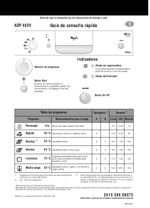
Whirlpool is a registered trademark of Whirlpool USA5019 396 98075ADP 4600Guía de consulta rápidaAntes de usar el lavavajillas lea las instrucciones de montaje y uso!(Reservado el derecho de introducir modificaciones técnicas)Añada sal regeneradoraLa sal debe añadirse inmediatamente antes de iniciar un ciclo de lavado.Añada abrillantador1)Programa de referencia para la etiqueta de datos energéticosconforme a la norma EN 50242;2)Vea “Uso del lavavajillas”;3)Datos relacionados con los programas, obtenidos conforme a la norma EN 50242. Los datos pueden variar en función de la carga, la temperatura (superior o inferior a 15°C), la dureza del agua, la tensión de alimentación, etc.Selector de programasBotón StartEl piloto se ilumina durante elfuncionamiento, parpadea cuando hay una anomalía y se apaga al final del programa.IndicadoresBotón On/OffTabla de programasDetergente 2)Consumo 3)ProgramasRecomendaciones para la cargaABLitros kWh MinutosPrelavado frío Vajilla que debe lavarse más tarde.--5,00,0210Rápido 40°C Vajilla poco sucia sin residuos secos.X -13,00,7030Normal 1)50°C Suciedad normal.XX16,01,05120Normal 65°C Suciedad normal o muy sucia.X X 16,01,65100Intensivo 70°C Programa aconsejado para vajilla muysucia, particularmente indicado parasartenes y ollas.X X 17,01,90135Media carga50°C Suciedad normal o ligera, o mitad de la carga normal.X X 13,00,87130Advertencia para los laboratorios de pruebas:Para obtener información más detallada sobre las condiciones de la prueba comparativa EN y de otras pruebas, escriba a la siguiente direccióndecorreoelectrónico:“*************************”.Cómo usar el lavavajillasPara mayor información lea las instrucciones de uso.Presione el botón ON /OFF.Compartimiento grande A:Cada ciclo de partimiento pequeño B:Sólo para programas con prelavado.Indicador mecánico C .Piloto eléctrico en el panel de mandos (si existe).Sólo si hay equipo de ablandamiento.Indicador mecánico D . Indicador eléctrico en el panel de mandos (si existe).Lea las instrucciones de carga.Se enciende el último programa seleccionado.Elija un programa (presionando el botón o mando).El piloto se enciende.Si es necesario (si existe). El piloto se enciende.El programa elegido queda memorizado (aunque se corte la corriente).-Abra la puerta sólo si es necesario (Atención: salida de vapor muy caliente).-Si el lavavajillas se apaga antes detiempo, cuando se vuelve a encender, el programa continúa desde donde se había interrumpido.Cuando se haya apagado el botón START: presione el botón ON/OFF . Todos los pilotos se apagan.Advertencia: cuando se abre la puerta, sale vapor muy caliente. Descargue el lavavajillas empezando por el cesto inferior.Encienda el lavavajillas Llenado del distribuidorde detergenteA B CControle el abrillantadorControle la sal regeneradoraCargue los cestos Cierre la puerta,abra el grifo de agua Seleccione el programaSeleccione lasfunciones suplementariasPresione el botón START“Cambiar programa”Mantenga presionado el botón START 2segundos hasta que el piloto Start se apague;Seleccione el nuevo programa y vuelva a presionar el botón START.C i c l o d e l a v a d oApague el lavavajillas Cierre el grifo de agua,descargue los cestosIndicaciones para la carga del lavavajillas y dotación de cestosCesto superior:según el modelo de lavavajillasSoporte multifunción (A): 1)Según la posición, utensilios largos, tazas y vasos. Son posibles tres posiciones.Soportes para la vajilla (B):Según la posición, platos, tazas y copas.Soporte para vasos giratorio (C): 2)Según la posición, vasos pequeños o copas.Los utensilios largos como, por ejemplo, tenedores de carne o cuchillos se han de colocar con la punta hacia el aparato.Media carga:Cargue sólo el cesto superior.Coloque el cesto de los cubiertos (D ) en el cesto superior.Regulación de la altura del cesto (vacío o cargado):•Regulación inferior: tire de las dos manillas del cesto (E ) hacia afuera y baje el cesto.•Regulación superior: tire de las dos manillas hacia arriba (E ) hasta que el cesto quede encastrado (esta es la regulación de fábrica).Los lados del cesto deben estar a la misma altura.Extracción del cesto superior para poder lavar platos grandes o bandejas en el cesto inferior:Abrir los seguros derecho eizquierdo (F ) de las guías del cesto y extraer el cesto superior.Cuando el cesto superior está colocado, los seguros deben estar cerrados.Cesto inferior:Según el modelo de lavavajillas, con soportes para platos rebatibles o fijos (G ).Media carga:Cargue sólo el cesto inferior.Mayor potencia de lavado sobre todo para platos y ollas.Cesto para los cubiertos (J) o (H):Algunos modelos están dotados de una rejilla (I ) para cubrir el cesto de los cubiertos. Cesto para los cubiertos (D ), si existe, sólo para aparatos con media carga.Los objetos que puedan causar heridas se han de colocar en el cesto con la punta hacia abajo.Utilice sólo vajillas aptas para el lavado en lavavajillas. No lave en el lavavajillas objetos no idóneos: piezas de madera o aluminio, utensilios de plástico, vajillas con decoraciones no esmaltadas, cubiertos de plata.Su revendedor le ofrece:1)Soporte multifunción (A) - N. serie AMH 369.2)Soporte para vasos giratorio (C) - N. serie WGH 1000.FFSeguro cerradoSeguro abiertoQué hacer en caso de...Si el lavavajillas presenta alguna anomalía de funcionamiento, verifique los siguientes detalles antes de llamar al Servicio de Asistencia (*vea el capítulo correspondiente en las instrucciones de uso).Problema Causa SoluciónEl lavavajillas nofunciona•No recibe agua.•Abra el grifo de agua.•El lavavajillas no carga suficiente agua.•Limpie el filtro de entrada del grifo del agua.•Verifique si el tubo de alimentación está doblado.•No hay corriente.•Enchufe la clavija en la toma de corriente.•Presione el botón START.•Cierre la puerta.•Controle el fusible de la casa.•Inicio del programa preseleccionado.•Si es necesario ponga el inicio del programa en “0”. Si la vajilla no quedaperfectamente seca•Abrillantador insuficiente.•Aumente la dosis*.•Queda agua en las cavidades de la vajilla.•Cargue la vajilla inclinada.Si la vajilla no queda perfectamente limpia •El chorro de agua no alcanza toda lasuperficie.•Coloque la vajilla de manera que las piezas no setoquen entre sí.Las cavidades de las piezas deben estar hacia abajo.•Detergente insuficiente.•Dosifique el detergente siguiendo las indicaciones delenvase.•Elección de un programa inadecuado.•Seleccione un programa de lavado más intenso.•Brazos aspersores bloqueados.•Los brazos aspersores tienen que girar libremente.•Boquillas de los brazos aspersoresatascadas.•Quite las impurezas que obstruyen el flujo del agua *.•Detergente no adecuado / demasiadoviejo.•Utilice un detergente de buena calidad.Residuos arenosos y granulares •Filtros atascados.•Controle regularmente los filtros y límpielos si esnecesario *.•Filtros mal introducidos.•Introduzca los filtros correctamente y bloquéelos *.Partes de plástico manchadas •Jugo de tomate / zanahoria,...•Según el material, si es necesario utilice undetergente con mayor poder blanqueador.Depósitos en la vajilla•poco adheridos•Rayas en la vajilla / en los vasos.•Aumente la dosis de abrillantador *.•Rayas / surcos en los vasos.•Reduzca la dosis de abrillantador *.•Capa de sal en la vajilla / en los vasos.•Cierre bien la tapa del recipiente de sal *.•muy adheridos•Ablandamiento del agua insuficiente,manchas calcáreas.•Regule el selector de la dureza del agua, si es necesario añada sal *.Vasos opacos / no brillantes •Este tipo de vasos no es lavable enlavavajillas.•Cargue vasos lavables en lavavajillas.Óxido en los cubiertos•No son de acero inoxidable.•Utilice cubiertos de acero inoxidable.Identificación de los errores del lavavajillas •El piloto START parpadea.•Indicador F... (si existe).•Compruebe que el conjunto de filtros no estéatascado y que la alimentaciónon del agua no estéinterrumpida (si fuera necesario, limpie los filtros *).Ponga de nuevo en marcha el programa. Mantengapulsada la tecla START durante 2 segundos, hasta quese apague el piloto correspondiente. Seleccione denuevo el programa y pulse la tecla START.Si tras efectuar los controles citados la anomalía persiste o se vuelve a presentar, apague el aparato y cierre el grifo del agua; luego póngase en contacto con el Servicio de Asistencia (las direcciones aparecen en la garantía).Tenga preparados los siguientes datos:•Tipo de anomalía.•Tipo y modelo de lavavajillas.•Código de asistencia (número de la etiqueta adhesiva de AsistenciaTécnica que está en la parte interior de la puerta, a la derecha)。
水利水电土建西班牙语词汇

水利水电土建西班牙语词汇水利水电词汇电站central f.水力发电厂planta hidráulica变电站subestación, subcentral发电generar, producir electricidad 流量caudal河床lecho del río枢纽punto clave大坝dique, presa弧形arco闸门compuerta水轮机turbina hidráulica轴流式水轮机turbina de flujo axial 混流式水轮机turbina mixta 反击式水轮机turbina de reacción冲击式水轮机turbina de impulsión 型号modelo参数parámetro变压器transformador轴eje轴承cojinete直径diámetro 轮叶aspas发电机generador电压voltaje, tensión电流corriente eléctrica功率potencia电阻resistencia阻抗impetancia电感inductancia电容capacitancia电容器condensador电流表amperímetro电压表voltímetro吊车grúa管路tubo, conducto栅empalizada开关interruptor隔离开关interruptor aislado闸刀开关interruptor de cuchilla 断路器cortador检测supervisar, monitorizar 避雷针pararrayos电源fuente de alimentación 结构图organigrama电路circuito集成电路circuito integrado回路bucle短路cortocircuito效率eficiencia磁铁imán磁magnetismo电磁的electromagnético弹簧muelle线圈/绕组bobina匝espila调节ajustar继电器relé热继电器relétérmico时间继电器reléde tiempo继电保护protección relevadora 相互关系,相互作用reciprocidad 气态的gaseoso汽油gasoleno交点intersección 导线alambre绝缘aislamiento绝缘体aislante电缆cable eléctrico插座enchufe维护mantenimiento抽象的abstracto横剖面sección transversal纵剖面sección longitudinal蜗壳concha尾水agua de cola用户usuario图cuadro,gráfico,diagrama 串联conexión en serie 并联conexión en paralelo电荷electrón电极electrodo分子molécula电工electricista电网sistema eléctrico电弧arco eléctrico向量/矢量vector垂直的perpendicular, vertical 平行的paralelo感光的fotosensible坐标coordenada横坐标abscisa纵坐标ordenada横线horizontal曲线curva线段segmento折线quebrada平行四边形paralelogramo对称的simétrico不对称的asimétrico函数función几何geometría接力器servomotor活塞pistón一次设备equipo primario二次设备equipo secundario测量仪器instrumentos de medida 截面sección 装置dispositivo 原线圈bobina original副线圈vice-bobina空载carga vacía误差error额定电压voltaje nominal电容式capacitivo熔断器fusible三相trifase铁芯núcleo de hierro 粉碎机trituradora按钮pulsador套管(变压器)borne风扇ventilador 储油盒depósito de aceite母线barra colectora铝aluminio零序secuencia cero正序secuencia positiva负序secuencia negativa后备的supletorio晶体管transistor焊接soldar熔化fundir座环corona硬度dureza耐久性durabilidad脉冲impulso法兰pesta?a剪断销pestillo导水机构conductor hidráulico立轴eje logitudinal卧轴eje transversal导叶杆barra de aspa连杆enlace空心的hueco膨胀espansión密封hermeticidad, hermético adj. 磨损desgastar, desgaste m. 摩擦系数coeficiente de fricción弹性elasticidad振荡<电> oscilación, vibración补气inflar, inflado m.橡胶垫圈retén沸腾ebullición 汽化vaporizar空蚀corrosión de aire空化机理mecanismo de cavitación水锤martillos de aguas氧化oxidar冲击,撞击esbestir划痕huella微粒partícula穿孔perforar光泽brillo, glaseado adj.泄露fuga f.尖利的aguzado惯性inercia电气的eléctrico干扰estorbar涡旋vórtice稳定性estabilidad不稳定性inestabilidad压缩comprimir严重化engravecer介质medio发电部departamento de generación流动性fluidez粘滞性viscosidad相位差desfase转速velocidad giratoria飞逸转速velocidad huida直角坐标coordenadas rectilíneas 矩形rectángulo反馈realimentación调速器regulador de velocidad 励磁excitación励磁起励excitación inicial浮充态estado de carga flotante 均充态estado de carga máxima 硫化vulcanización硫化物sulfuro集水井pozo de almacenamiento 分离器separador储气罐tanque del gas消防室cámara por incendio高程escalón冲洗池fregadero厂房taller 双投开关inversor复归reponerse气压机compresor de aire消防水泵bomba para incendio风机ventilador消毒desinfectar连片conectar开关操作把手contactor验电器electroscopio验电笔busca-polo电动势potencial electrodinámico 电枢反应reacción de inducido外径diámetro externo整流型rectificador强度intensidad转换器conmutador气态estado gaseoso模拟信号se?al simulada数字信号se?al digital水银温度计termómetro de mercurio 集气瓶recipiente槽pesebre汛期temporada de crecida推力轴承cojinete de presión过滤器filtrador, filtro空气冷却器radiador de aire停电apagón阀门válvula逆止阀válvula contra inversión蝴蝶阀válvula de mariposa盘型阀válvula de plato备用阀válvula de reserva阀组grupo de válvulas轴瓦forro de eje弹性elasticidad排污suspilo, descarga水池algibe风闸cerrodo杂质impureza集油槽depósito de almacenamiento del aceite压油罐depósito de aceite de presión 浮子flotador 通气孔agujero de ventilación 消火栓manguera示波管osciloscopio示波器oscilógrafo分瓣键pasador(大锤)击mazobear大锤mazo套筒manguito链条polea防水的impermeable数据处理procesamiento de datos传感器sensor <工> transductor <电>互感器inductancia mutua酸值índice de ácido硅胶gel de sílice粘度viscosidad乳化emulsión乳化剂agentes emulsificantes再生器regenerador手轮volante取样muestreo火线alambre cargado零线alambre neutral中和neutralizar导电性conductibilidad 腐蚀corroer老化envejecimiento 有机orgánico沉淀precipitación氢氧化物hidróxido厚度espesor呼吸器respirador吸附剂adsorbente防腐剂conservador饱和saturación单相的monofásico三相的trifásico不锈钢acero inosidable 萃取extracción提纯purificación蒸馏水agua destilada 甘油glicerina外壳caparazón纤维fibra比色计colorímetro 异步电动机motor asincrónico步进电动机motor de avance gradual 电抗reactancia 锈herrumbre裂痕raja变阻器reóstato膜película水溶性的hidrosoluble渗漏infiltración拧紧apretar巡回ambulante砂眼poro脱落desprenderse凸轮leva潜水泵bomba de buceo油污mugre耐压aguante摇表megóhmetro屏蔽环anillo apantallado铅皮lámina de plomo电站central f.水力发电厂planta hidráulica变电站subestación, subcentral发电generar, producir electricidad 流量caudal河床lecho del río枢纽punto clave大坝dique, represa弧形arco闸门compuerta水轮机turbina hidráulica轴流式水轮机turbina de flujo axial 混流式水轮机turbina mixta 反击式水轮机turbina de reacción冲击式水轮机turbina de impulsión 型号modelo参数parámetro变压器transformador轴eje轴承cojinete直径diámetro轮叶aspas发电机generador电压voltaje, tensión 电流corriente eléctrica功率potencia电阻resistencia阻抗impetancia电感inductancia电容capacitancia电容器condensador电流表amperímetro电压表voltímetro吊车grúa管路tubo, conducto栅empalizada开关interruptor隔离开关interruptor aislado闸刀开关interruptor de cuchilla 断路器cortador检测supervisar, monitorizar 避雷针pararrayos电源fuente de alimen tación 结构图organigrama电路circuito集成电路circuito integrado回路bucle短路cortocircuito效率eficiencia磁铁imán磁magnetismo电磁的electromagnético弹簧muelle线圈/绕组bobina匝espila调节ajustar继电器relé热继电器relétérmico时间继电器reléde tiempo继电保护protección relevadora 相互关系,相互作用reciprocidad 气态的gaseoso汽油gasoleno交点intersección导线alambre绝缘aislamiento绝缘体aislante电缆cable eléctrico 插座enchufe维护mantenimiento抽象的abstracto横剖面sección transversal纵剖面sección longitudinal蜗壳concha尾水agua de cola用户usuario图cuadro,gráfico,diagrama 串联conex ión en serie 并联conexión en paralelo电荷electrón电极electrodo分子molécula电工electricista电网sistema eléctrico电弧arco eléctrico向量/矢量vector垂直的perpendicular, vertical 平行的paralelo感光的fotosensible坐标coordenada横坐标abscisa纵坐标ordenada横线horizontal曲线curva线段segmento折线quebrada平行四边形paralelogramo对称的simétrico不对称的asimétrico函数función几何geometría接力器servomotor活塞pistón一次设备equipo primario二次设备equipo secundario测量仪器instrumentos de medida 截面sección 装置dispositivo原线圈bobina original副线圈vice-bobina空载carga vacía误差error 额定电压voltaje nominal电容式capacitivo熔断器fusible三相trifase铁芯núcleo de hierro 粉碎机trituradora按钮pulsador套管(变压器)borne风扇ventilador 储油盒depósito de aceite母线barra colectora铝aluminio零序secuencia cero正序secuencia positiva负序secuencia negativa后备的supletorio晶体管transistor焊接soldar熔化fundir座环corona硬度dureza耐久性durabilidad脉冲impulso剪断销pestillo导水机构conductor hidráulico立轴eje logitudinal卧轴eje transversal导叶杆barra de aspa连杆enlace空心的hueco膨胀espansión密封hermeticidad, hermético adj. 磨损desgastar, desgaste m. 摩擦系数coeficiente de fricción弹性elasticidad振荡<电> oscilación, vibración补气inflar, inflado m.沸腾ebullición汽化vaporizar空蚀corrosión de aire空化机理mecanismo de cavitación电力工程词汇地回路电流circuito de retorno por tierra控制电路circuito de control选择性电路circuito selectivo ;选择电路circuito selector二次电路circuito secundario;主电路,干线circuito principal;原电路circuito primario;多相电路circuito polifásico;振荡电路circuito oscilante;栅极电路circuito de rejilla;反馈电路circuito de realimentación;闭合电路circuito cerrado;双向电路circuito bifilar;附加电路circuito aplicado;分支电路circuito derivado平行馈电alimentación en paralelo电应力tensión eléctrica ;机械应力tensi ón mecánica相位fase;故障电路avería直流电源red de corriente continúa / fuente alimentadora de C.C;负荷carga额定电压voltaje nominal额定频率frecuencia nominal三相短路cortocircuito trifásico临时停电apagón momentáneo无定向电流,无差电流corriente estática漏(泄)电流,漏流corriente de fuga感应电流,法拉第电流corriente farática电动电流(指稳定的直电流)corriente galv ánica过电压sobretensión相电流corriente de fase零序电压voltaje de secuencia cero频率frecuencia;功率因子factor de potencia电能energía eléctrica额定值valor nominal端电压voltaje del terminal绝缘等级grado de aislamiento 额定次级电流corriente secundaria nominal 额定动态电流corriente dinámica nominal 额定输出exportación nominal停电apagón串联电路circuito en paralelo并联电路circuito en serie感应电路circuito inductivo感应器inductor检波电路circuito detector振荡电路circuito oscilatorio缓冲电容器condensador de absorción耦合电容器condensador de acoplamiento 电容耦合acoplamiento capactivo紧耦合(连接)acomplamiento cerrado弱(松)耦合acomplamiento fluídico电导耦合acomplamiento conductor临界耦合acomplamiento crítico交叉耦合acomplamiento cruzado可变耦合acomplamiento variable交流耦合acomplamiento de corriente alterna直流耦合acomplamiento de corriente continua电感耦合acomplamiento óptico涡流,傅科电流corriente de Fouaut防放电,过电压及牵引回路电流保护系统sistema de protección contra descargas eléctricas, sobretensiones y corriente de tracción de retomo防雷,过电压保护及接地sistema de protección contra royos, sobre tensiones y corriente de retorno a tierra真空断路器disyuntor en vacío自动断路器disyuntor automático双投断路器disyuntor de doble dericción真空接触器contactor en vacío电流互感器transformador (inductancia mutua) de corriente (el CT)电压互感器transformador (inductancia mutua) de tención (el PT)一次和二次熔断器fusible primario ysegundario断电器relé电压调节器regulador de la tensión整流器conmutador / rectificador初级熔断器fusible primario中压开关interruptor de tesión media母线barras colectoras二次侧母线La barra lateral secundaria母线开关el interruptor de barra一次侧绕组devanado(绕组) primario牵引变压器trasformador de tracción电力变压器trasformador de potencia电动隔离开关seccionador eléctrico手动隔离开关seccionador mecánico土建水电词汇Replanteo 放样Limpieza清表debroce 清表(强调植被的清除)Las boras viviles 土建工程Especificaicones tecnicas 技术规范Captaicon del rio 或者toma 取水Area del ambalse 蓄水区域Presa大坝Obras anexas附属工程Area de prestamos 租界区域Areas vecinas 临近区域Taludes边坡Forma de pago支付方式Obras de desvio 倒流工程Excavacion开挖Desvio del rio 河水倒流Desalojo del agua de fundacion 基底排水Cuidado del rio 河流的维护Cierredel tunel隧洞的封堵Tapon de hormigon混凝土堵头Las instalaciones temporales临时设施Ataguia围堰La margen河岸Dique防护墙(导流工程出口处防止倒流水冲击的设施)Desvio definitivo最终倒流Desalojo del auga de fundacion 基底排水Excavacion a cielo abierto 明挖,露天开外Metodologia 方案(监理整天大事小事都要有方案才同意)Dimension 尺寸Asentamiento基础Precaucion预防措施Derrumbe 塌方Erosion 剥蚀Sobre excavacion过度开挖,超挖(隧洞里最怕这个,一旦超挖还要填回去,还要自己承担费用)Empotramiento de la presa 大坝嵌入Voladura爆破Disposicion de materales de excavacion开挖料Entibado支撑Ancelaje ,peno锚杆Barra de anclaje 锚铁棒Anclage postensado 后拉紧锚索Red metalica,malla metalica金属网,钢网Hormigon lanzado喷混凝土Seccion con entibado支撑面Gavion石笼Enrocado堆石Enrocado hormigonado 混凝土堆石Preconsolidacion 预先固结Tratamiento superficail表面处理Acabado del hormigon 混凝土收尾Cuirado养护Juntas impermeable 防水连接Inferferencia entre obras 工程妨碍Control de voladura 爆破控制Iluminacion 照明Ventilacion通风Drenaje排水Ruido噪音Explosivo爆破物Tunel 坑道Pozo矿井TBM隧道挖掘机Tunel para construccion施工通道Perforacion 钻井Perforaciones para drenaje排水钻井Perforacion prar inyeccion 灌浆钻井Evacuacion del agua en daleria巷道排水Evacuacion del agua en pozo 矿井排水Captacion de filtraciones e impermeabilzacion 防水渗漏系统Cemento 水泥Tipo de cemento 水泥,水泥标号Trasporte 运输Almacenamiento存储Fuentes de abastecimiento 供应源Agregado骨料Diseno de mezacla 配合比Impureza indeseable 有害杂质Granulometria粒径Agregado fino 细骨料Agregado grueso粗骨料Agregado manufacturado 加工的骨料Aditivos quimico化学添加剂Acelerante速凝剂Introductores de aire 引气剂Reductores de agua retardante 缓凝减水剂Microsilica 微硅粉Dosificaicon de hormigon 配比Clases de hormigon 等级Contenido de cemento 水泥含量Hormigon ciclopeo 大体积混凝土Mortero para instalacion de quipo 设备安装所用砂浆Proporcion de las mezclas 拌合比例Preparacion del hormigon 混凝土拌合Plantas dosificadora配比站Dosificaicon de materiale 材料配比Aditivio 添加剂Balanza 称量Mezcladora estacionarias 固定拌和站Mezcladora moviles 移动拌和站Encofrado模板Encofrado curvos prar trasiciones 过渡弯曲模板Sujecion de los encofrado 模板固定Hormigon de segunda stapa 二期混凝土Compactacion振捣Cuirado de agua 水养护Cuirado del hormigon de alta resistencia 高抗混凝土养护Laboratorio实验室Reparaciones del hormigon 混凝土修复Acabados 混凝土收尾Superficies de hormigon a la vista 可见混凝土表面Superficies formada sin encofarado非模板形成的表面Inyeccion灌浆Bubdivision de los trabajos工作细化Perforadora凿岩机Permeabilidad con agua渗水性Planta de ynyeccion灌浆车间Tuberias管道系统Mezcals灰泥Arena 沙子Aditivos添加剂Secciones 截面Tramos地段Inyecciones de contacto 接触灌浆Inyecciones de consolidacion加固灌浆Inyeccion a presion 高压灌浆Inyecciones de cavidades de gran volumen 打孔灌浆Tramos de prueba de inyeccion灌浆试验地段Parametro de inyeccion 灌浆参数Memoria descriptiva de la metodologia del contratista 承包商工作方法报告Criterios de suspension de la inyeccion 悬液灌浆的标准Lechadas 砂浆Inyeccion de impermeabilizacion 防水灌浆Inyecciones con tubos valvulado阀管的灌浆Acero de refuerzo 钢筋Fibra de acero 钢纤维Mallas electrosoldad 电焊Soportes支架Pernos 螺栓Electrodos 电极Piezas forjadas 铸件Galvanizado 镀锌Examenes mediante ensayos no destructivo 通过无损性测试Montaje 装配。
A conceptual model completely independent
A conceptual model completely independentof the implementation paradigmOscar Diestea,*,Marcela Genero b,1,Natalia Juristoc,2,Jos e L.Mat ec,2,Ana M.Moreno c,2aDepartamento de Electr onica y Sistemas,Escuela Polit e cnica Superior,Universidad Alfonso X el Sabio,28691-Villanueva de la Ca ~n ada,Madrid,SpainbDepartamento de Informatica,Escuela Superior de Informatica,Universidad de Castilla-La Mancha,Paseo de la Universidad,4,13071Ciudad Real,SpaincDepartamento de Lenguajes y Sistemas,Inform a ticos e Ingenier ıa del Software,Facultad de Inform a tica,Universidad Polit e cnica de Madrid,28660-Boadilla del Monte,Madrid,SpainReceived 23December 2002;accepted 27December 2002AbstractSeveral authors have pointed out that current conceptual models have two main shortcomings.First,they are clearly oriented to a specific development paradigm (structured,objects,etc.).Second,once the conceptual models have been obtained,it is really difficult to switch to another development paradigm,because the model orientation to a specific development approach.This fact induces problems during development,since practitioners are encouraged to think in terms of a solution before the problem at hand is well understood,thus anticipating perhaps bad design decisions.An appropriate analysis task requires models that are independent of any implementation issues.In concrete,models should support developers to understand the problem and its constraints before any solution is identified.This paper proposes such an alternative approach to conceptual modelling,called ‘‘problem-oriented analysis method’’.Ó2003Elsevier Inc.All rights reserved.Keywords:Conceptual modelling;Generic conceptual model;Development orientation1.IntroductionRequirements engineering (RE)activity is composed by four iterative tasks:elicitation,analysis,documen-tation and validation (SWEBOK,2000).Of these tasks,analysis is one of the most critical,due to the huge im-portance of its goals:(1)understand the problem to be solved;(2)develop conceptual models (CMs),which represent the problem understanding;and (3)define the features of an implementation-independent solution tothe problem in question,that is,identify the require-ments to be satisfied by the future software system.CMs play a central role during analysis,since they make possible to•make real-world concepts and relationships tangible (Motschnig-Pitrik,1993);•record parts of reality that are important for per-forming the task in question and downgrade other el-ements that are insignificant (Borgida,1991);•support communication among the various ‘‘stake-holders’’(customers,users,developers,testers,etc.)(Mylopoulos et al.,1997);•detect missing information,errors or misinterpreta-tions,before going ahead with system construction (Schreiber et al.,1999).Conceptual modelling is gaining in importance as software systems become more complex and the problem*Corresponding author.Present address:Departamento de Sist-emas Informaticos y Programacion,Facultad de Informatica,Uni-versidad Complutense de Madrid,Ciudad Universitaria S/N,28040Madrid,Spain.Tel.:+34-91-394-75-46.E-mail addresses:odiestet@fdi.ucm.es (O.Dieste),marcela.gen-ero@uclm.es (M.Genero),natalia@fi.upm.es (N.Juristo),jlmate@fi.upm.es (J.L.Mat e ),ammoreno@fi.upm.es (A.M.Moreno).1Tel.:+34-926-29-54-85x3740.2Tel.:+34-91-336-6922/6921/6929.0164-1212/$-see front matter Ó2003Elsevier Inc.All rights reserved.doi:10.1016/S0164-1212(03)00061-XThe Journal of Systems and Software 68(2003)183–198/locate/jssdomain moves further away from knowledge familiar to developers.In complex domains,to understand the user need becomes more difficult and,therefore,conceptual modelling grows to be crucial.Several researchers claim that proper conceptual modelling is crucial since it helps to represent the problem to be solved in the user domain(McGregor and Korson,1990;Bon-fatti and Monari,1994;Høydalsvik and Sindre, 1993).Nevertheless,several authors have argued that the CMs used nowadays are oriented to specific software development approaches.This orientation has two re-percussions:(1)CMs have computational constraints, that is,CMs developers represent specific implementa-tion characteristics in the domain models(Bonfatti and Monari,1994;Høydalsvik and Sindre,1993;McGinnes, 1992);(2)CMs prescribe the subsequent development process,in which the CMs are more or less directly transformed into design models(Henderson-Sellers and Edwards,1990;Davis,1993;Jalote,1997;Northrop, 1997;Juristo and Moreno,2000),and their trans-formation to a design model related to another de-velopment paradigm is exceedingly complicated and sometimes impossible.This means that the CMs used nowadays are not appropriate for analysis.In this paper,we propose an alternative approach that aims to remove the above constraints.The paper is structured as follows:Section2 discusses the problems with using CMs identified by several researchers,and establish the requirements for an appropriate CM.Sections3and4describe our ap-proach for a conceptual modelling process independent of any development paradigm.Finally,the preliminary results of applying our approach are discussed in Sec-tion5.2.The computational orientation of conceptual modelsThe term CM originally emerged in the database field.CMs were used to represent the data and relations that were to be managed by an information system,ir-respective of any implementation feature.Nevertheless, CMs are used for more than is acknowledged in data-bases.CMs are used in RE to•encourage the analyst to think and document in terms of the problem,as opposed to the solution (Davis,1993);•describe the universe of discourse in the language and in the way of thinking of the domain experts and users(Beringer,1994);•formally define aspects of the physical and social world around us for the purposes of understanding and communication(Loucopoulos and Karakostas, 1995);•help requirements engineers understand the domain (Kaindl,1999).Taking into account the above definitions,the main characteristics of any CM can be said to be description and understanding.That is,CMs should be used by de-velopers to•understand the user needs;•reach agreement with users on the scope of the system and how it is to be built;•use the information represented in the model as a ba-sis for building a software system to meet user needs.Several authors have pointed out that current CMs sometimes fail to do their jobs of description and un-derstanding during analysis.Criticisms can be divided into two major groups:•The orientation of the conceptualisation methods, stressing the fact that most CMs are oriented to get-ting a computational solution to the problem or need raised and not to easing the understanding of the user need.For instance,regarding to object orientation: It is argued that object-oriented methods are a ÔnaturalÕrepresentation of the world.Nevertheless, this idea is a dangerous over-simplification (McGinnes,1992).Object-oriented analysis has several shortcomings, most importantly in being target oriented ratherthan problem oriented(Høydalsvik and Sindre,1993).Object-oriented analysis techniques are strongly affected by implementative issues(Bonfatti and Monari,1994).Thus,for example,dataflow diagrams(DFD)are clearly guided by functions,the key components of structured software,and,likewise,the models used in object-oriented analysis lead directly to software de-veloped by means of classes,objects,messages, polymorphism,etc.,the basic concepts of object-ori-ented software.•The association between CMs and specific ap-proaches to software development.Here,the use ofa given CM during early phases of the developmentlimits the number of possible implementation alterna-tives and means that only the options that are com-patible with the CM used originally are feasible.If computational characteristics are included in CMs,these are linked to a particular implementation approach,that is,once a given conceptualisation method has been selected to describe the problem do-main,it is practically impossible to change the above method a posteriori without having to reanalyse the problem.This has also been stressed by several re-searchers:184O.Dieste et al./The Journal of Systems and Software68(2003)183–198Because of a poorly understood overlap among different requirements languages,it is difficult tochange languages mid-project(Davis et al.,1997).The use of a CM during analysis defines nearly univocally how the design shall be done(Hender-son-Sellers and Edwards,1990).Perhaps the most difficult aspect of problem anal-ysis is avoiding software design(Davis,1993).It is sometimes mistakenly believed that the struc-tures produced during analysis will and should becarried through in design(Jalote,1997).The boundaries between analysis and design activ-ities in the object-oriented model are fuzzy(Nor-throp,1997).The CM used preconditions the software system development approach(Juristo and Moreno, 2000).Owing to this limitation,if dataflow diagrams have been used to model the problem domain,for example,it will almost certainly be necessary to use the structured method in later development phases;whereas a method of object-oriented development will have to be used following upon an object-oriented analysis.Therefore,if we intended to switch development paradigms,that is, for example,pass from a dataflow diagram to an object-oriented design,this transformation would lead to an information gap that is very difficult tofill.This occurs because each CM acts like a pair of glasses used by the developer to observe the domain and user reality.These glasses highlight certain features,tone down others and hide others.Once the real world has beenfiltered through the CM,it is difficult to retrieve anything that has been lost or condensed,even if the later development process requires this information.The only way of recovering the features lost in the CMfilter is to reanalyse reality using a different pair of glasses;that is,to repeat the operation using another CM.Authors like Coleman et al.(1994), Champeaux et al.(1993)or Wieringa(1991)have already discussed this situation,addressing the incompatibility between the CMs used in the structured approach and object-oriented CMs,owing to the conceptual difference between the elements used in both approaches.In short,the software system development approach can be said to be preconditioned from the very start,as soon as the CMs are built.The problem with including computational considerations within the CM is that developers are forced to make a solution-oriented deci-sion during the early development phases,when the problem to be solved is still not well enough understood. This means making design decisions when not all the information relevant to the problem is known.Devel-opers thus run the risk of making the wrong decision, because they are not in possession of all the information. Excepting trivial problems,this precondition implies that the development approach is chosen before the user need has been understood,which is the job of concep-tual modelling.Even worse,very often the CMs selected are models with which developers are familiar,models called for by individual standards or even,as specified by Mylopoulos et al.(1999),the models that are‘‘in fashion’’.So,in the era when the structured approach was in vogue,techniques such as DFDs were used for conceptual modelling,whereas,today,with the rise of object-oriented programming and design,techniques like object diagrams,interaction diagrams,etc.,are employed for problem analysis.In order to avoid the commented problems of current CMs,they should include all the information required about the problem for developers to later address the software system that is to solve the user problem.In-deed,it is needed that conceptualisation methods meet the following:•Understanding the need raised by the user before considering an approach for developing a software system that meets this need.•The understanding of the need must be independent of the chosen problem-solving approach,that is,it must not precondition the use of any development approach.•Having criteria for deciding which is the best develop-ment approach once the user need has been under-stood.These criteria can only be met by redefining the conceptual modelling process as it is now carried out in the RE analysis task.3.An implementation-paradigm independent conceptual modelThe proposed approach,called‘‘problem-oriented analysis method’’(POAM),tries to meet the above-mentioned criteria,and is characterised by(1)using representation diagrams,which we call generic concep-tual models(GCMs),that do not presuppose any im-plementation paradigm;(2)defining a detailed analysis process;and(3)deriving,from the GCM,the best-suited CM(that is,a CM now used in RE,like DFD,use cases, etc.)to continue with development according to the methods used nowadays.The following sections present the main components of the proposed approach,that is, the GCM,which is described in Section3.1,and the POAM process,which is discussed in Section3.2.3.1.Generic conceptual modelThe CMs currently used in software engineering have to be used exclusively,that is,mostly rule out the use ofO.Dieste et al./The Journal of Systems and Software68(2003)183–198185a complementary CM.In some cases,when using a DFD,for example,the use of supplementary notations, such as process specifications or even the entity/rela-tionship model,is permitted,although these are sub-ordinated to the process diagram set out in the DFD.The GCM proposed in this approach is based on complementariness.Instead of using a representation schema that dominates the modelling process,three complementary representation schemas are -plementary means:(1)each schema supports the others, satisfactorily recording information they do not repre-sent and(2)the information in one schema can migrate, that is,move from one schema to another without the GCM losing information.Complementariness is important because the way the information is expressed benefits or impairs its under-standing(Vessey,1991).The different components of the GCM can represent the same information,expressing it either as a graph,table or text.This means that each analysis process participant can select and use the best-suited expression,either on the basis of previous expe-rience or in accordance with current needs.The proposed GCM components are as follows:•Element maps:Information representation structures belonging to a given knowledge domain or problem.Element maps are variations on the conceptual maps, derived from the work of Ausubel on Learning The-ory and Psychology,later formalised by Novak andG owin(1984).We use the termÔelement mapsÕin-stead ofÔconcepts mapsÕ,becauseÔconceptÕis a over-loaded word in SE.For example,ÔconceptÕis often used to meanÔdataÕ.When we useÔelementÕ,we are talking aboutÔstatic conceptsÕ,like data,rules or facts,but also aboutÔdynamic conceptsÕ,like pro-cesses,events,and so on.Conceptual maps(as employed in psychology)can be used to express and graphically represent concepts and associations between concepts as a hierarchical struc-ture.Element maps differ from conceptual maps used in Psychology on three essential points:(1)they are gen-erally structured as a complex graph and not necessarily hierarchically;(2)both the concepts(elements in our approach)and the associations,which represent estab-lished knowledge in conceptual maps,are likely to evolve over time as the analysis progress and(3)some special concepts(elements in our approach)and asso-ciations have been defined to restrict the spectrum of possible readings of the elements map for the purpose of raising the efficiency of POAM application.•Dictionaries:Tabulated information representation schemas.Dictionaries have a set of predefinedfields that define what sort of information they record.There are two main types of dictionaries:Identificative dictionary(or glossary):This dictio-nary merely records the information required torecognise a element or association appearing whileinvestigating the problem and to distinguish oneelement or association from another.Descriptive dictionary:Its goal is to record negoti-ated information about elements and associations,that is,information that all the participants in the analysis process agree to be true.This information is,additionally,practically complete,that is,all the important aspects of the problem and its solution will have been identified and recorded if this dictio-nary has been correctly built.•Narrative description:Natural language text that describes the information recorded in the elements map and the dictionaries.The narrative description can be automatically derived from the elements map and dictionaries(although the result is not a literary masterpiece),which has some clear benefits for model validation.The text is very understandable for end users and,as there is a bijective relationship between the narrative description and the other representation schemas,the comments and corrections made by the users can be fed back into those schemas.The three above-mentioned representation schemas are used during the POAM process activities and steps. The POAM process is described below.3.2.Generic conceptual model development processThere are two points of inflection during analysis, each determined by its goals,that is:(1)move from ig-norance to an understanding of the problem to be solved,which should be reflected in the creation of CMs, and(2)go from an understanding of the problem to a solution characterization,which moves from a very abstract level in the early stages of analysis(some re-strictions,characteristics,etc.,of the future software system)to a more concrete formulation as the devel-operÕs knowledge about the problem increases(a list of the desired software system features).Therefore,the proposed process is composed of two activities,as shown in Fig.1(a).The two activities differentiate two states in analysis:a problem-oriented state and a solu-tion-oriented state.The goal of thefirst activity,called problem-oriented analysis,is to understand the problem to be solved and ends when the GCM,which represents the acquired knowledge,has been developed.This G CM is the input for the second activity,called software-oriented analysis, whose goal is to identify which typically used CM is best suited for representing the problem,as well as to transform the GCM into the above-mentioned CM.Thisfirst level of decomposition is too general to guide a developer as to how to perform analysis. Therefore,both activities are divided into two steps,as shown in Fig.1(b),which are further broken down into186O.Dieste et al./The Journal of Systems and Software68(2003)183–198detailed tasks.Thus,problem-oriented analysis is de-composed into the following steps:•Preliminary analysis:In this step,the problem is ex-amined superficially with the aim of defining a prelim-inary model.The goals of this step are to(1)identify the most important elements of the problem domain;(2)describe these elements;and(3)organise all theelements of the problem domain into a structure, by means of which to define the associations there are among these elements.•Comprehensive analysis:In this step,the problem is studied in as much detail as required to develop the comprehensive model,that is,the complete GCM.The goals of this step are to(1)check that the impor-tant problem elements have been identified;(2)de-scribe the above elements exhaustively and(3) clearly determine the associations among elements.In the above paragraphs,we introduced the concepts of preliminary and comprehensive models.The prelimi-nary model is a simplified version of the GCM,obtained after the preliminary analysis,which is composed of(1)a elements map––usually hierarchical and not generally a graph,(2)identificative dictionary and(3),narrative descriptions.The comprehensive model,that is,the complete GCM output at the end of the comprehensive analysis,differs from the preliminary model in that(1) the elements map is more detailed and is generally a graph,(2)the descriptive dictionary is used instead of the identificative dictionary and(3)the narrative de-scription is optional and is usually excluded.Having completed the problem-oriented analysis,we will get an exhaustive description of all the important problem elements and of the spectrum of associations between these elements.This information,contained in the GCM,is of intrinsic value,as it helps developers and other participants in analysis to understand the prob-lem,which is one of the key objectives of analysis.Using the proposed approach,however,we can go even further to derive,from the information contained in the GCM,a CM by means of which to continue software system development using any of the develop-ment approaches now available,such as structured, object-oriented or real-time approaches.That CM is derived in the software-oriented analysis activity.This activity is decomposed into two steps.Identification of the suitable conceptual model:In this step,we identify the suitable conceptual model (SCM).The SCM is the target CM that can represent all the information gathered in the GCM for a given problem more fully.An interpretation procedure has to be applied to the G CM to identify the SCM.The interpretationO.Dieste et al./The Journal of Systems and Software68(2003)183–198187procedure can be used to rewrite the GCM from a computational viewpoint,that is,to assign builders used by the classical CMs to the constituent elements of the GCM,which in turn form the building blocks of com-puter systems.We have used a requirements representation formal-ism proposed by Davis et al.(1997)for rewriting pur-poses,although it has been profoundly modified for use with the G CM.This formalism,termed‘‘canonical model’’,in accordance with its authorÕs intent,provides a set of building blocks that can be used to represent the information contained in a range of CMs.This means that it can be used as a lingua franca,which averts,as explained below,having to deal with each CM sepa-rately.The interpretation procedure,therefore,involves as-signing a computational interpretation to each of the building blocks of the GCM or,in other words,as-signing each GCM element to one of the canonical model elements.This assignation will be totally formalised and engi-neer independent,unless any ambiguities arise in the assignation.Ambiguity is the possibility of assigning two or more elements of the canonical model to any given G CM element.In this case,it is the engineer who has to decide,depending on the semantics of the GCM and the canonical model,which particular interpretation is the best suited.After interpretation,the GCM is called the require-ments canonical model(RCM),as the GCM can now be read in computational terms,as a description of what should be future software system operation.After out-putting the RCM,we can determine the SCM.The SCM will be the CM that is capable of repre-senting most RCM propositions.We have defined a measure,calledfitness,to give a quantitative value of suitability.Fitness is defined as the ratio between the propositions a given CM can represent and the total number of RCM propositions.Accordingly,the SCM is the CM with the highestfitness value.Additionally,this measure provides supplementary information,namely,the extent to which the SCM is suitable.For example,a CM may be suitable(that is,be the best of all the models)and still very partially rep-resent the information gathered about the problem do-main(in this case,lowfitness values would be obtained). Additionally,it can even establish what difference,in terms of representation capability,there is between two particular CMs(which would be the difference between the respectivefitness values).Derivation of the selected conceptual model:In this step,the RCM is translated into the target CM.We use a derivation procedure to generate the target CM.The derivation procedure basically involves using a set of derivation tables and rules.There are as many tables as there are possible target CMs.Each derivation table contains all the possible combinations of canonical model elements that can be expressed in a given target CM,along with the expression of this combination in the particular format used by the CM in question (graphs,text,tables,etc.).As each GCM element has been labelled in the RCM and we have calculated thefitness of the different CMs, we can now refer to the appropriate derivation table and use it to directly generate fragments of the target CM. These fragments can later be assembled,unambigu-ously,tofinally output the correct target CM.The derivation rules modulate the use of each deri-vation table,altering the RCM in a controlled manner, so that the target CMfinally obtained resembles as closely as possible a target CM developed independently for the same problem.The target CM obtained in the above step can be refined by entering more information.However,this refinement is neither direct,nor can it be formalised, owing to the fact that the GCM cannot be interpreted directly in computational terms.Therefore,the devel-oper will have to select what knowledge to record in the target CM and what to discard.Once complete,the target CM will have the same drawbacks as CMs de-veloped directly,that is,some knowledge about the problem will have been lost and the target CM will be linked to a given development approach.Nevertheless, there is a big difference betweenfiltering problem ele-ments using the current and the proposed conceptual modelling processes.With the development processes now in use,developers do not take into account the problem elements that are not compatible with the CM used(DFD,use cases,etc.)before the problem is ing the proposed approach,developers are encouraged to study and record all the possible problem perspectives in the G CM.Therefore,the loss of knowl-edge occurs when the problem has been understood,thus avoiding early decisions on how to solve the problem at hand.4.Conceptual modelling using our proposalAn example showing the steps of the proposed pro-cess,as well as the use of the components of the GCM is given in the next section.This example will illustrate all the theory explained above.Suppose we have the fol-lowing problem,set out in natural language: Hospital123has two patient admission procedures.Thefirst is the admission of patients on a waiting list.The second is the admission of patients who visit the emergency department.When a patient on a waiting list is admitted,the patient is assigned a room on a ward depending on the com-188O.Dieste et al./The Journal of Systems and Software68(2003)183–198plaint that is to be treated.For example,if a patient is to undergo coronary by-pass surgery,the patient would be assigned to a room on the cardiology ward.The patients admitted from the waiting list are assigneda reference physician.This physician can be any doctorbelonging to the speciality related to the complaint that is to be treated.On the other hand,patients who are admitted from the emergency department are immediately treated prior to any administrative procedure.Once treated,they are assigned a room no later than three hours after admis-sion,according to the same rules as patients admitted from the waiting list.The only difference is that their reference physician will be the doctor who treated them in the emergency department rather than a physician of any particular speciality.Atfirst glance,this problem could apparently be modelled in several different ways.For example,given the problem characteristics(objects present,transfor-mation processes that seem to exist,etc.),a dataflow diagram would appear to be a suitable representation,as would an entity/relationship or a class diagram.How-ever,the use of POAM makes it unnecessary to hy-pothesize,in this moment,which is the best-suited diagram type.During analysis,the problem is modelled using the GCM and,only later,before passing on to design,will we decide which is the best-suited CM and, depending on this decision,which development ap-proach will be most effective for building the future software product.Thefirst step of POAM is preliminary analysis.As this is not a real case,but a test case where(1)the in-formation is not acquired incrementally,as happens during elicitation,(2)there are no ambiguities and(3) complexity is controlled at minimum levels,the model-ling output after preliminary analysis would be ap-proximately as shown in Fig.2.Fig.2shows the preliminary element map.This map shows the key elements present in the problem descrip-tion(patients,doctors,rooms,wards,etc.),as well as the key associations(a patient is admitted from the waiting list or the emergency doctor is the reference physician of an emergency patient).The preliminary element map is easily confused,during preliminary analysis,with se-mantic data models or class diagrams.However,this is only a seeming similarity,as,in this intermediate step of POAM,we have mainly described the structural aspects of the problem,which are,precisely,the aspects on which the above-mentioned conceptual models focus.The preliminary elements map can be likewise ex-pressed by means of the identificative dictionary,or glossary,shown in Table1or by means of narrative text, as shown in Table2.Note that each representation is similar to,while,at the same time,slightly different from,the others.This is due to the fact that each GCM representation mecha-nism focuses on different aspects of the information acquired.The element map highlights,primarily,the associations between the different elements,whereas theO.Dieste et al./The Journal of Systems and Software68(2003)183–198189。
Departamento de Electr'onica y Tecnolog'ia de Computadores
2 State of the art
Not many references have been found about similar work, but they are related to macroscopic models, like for instance, the mathematical advertising di usion model due to G. Feichtinger 1], used to demonstrate that the optimal policy of advertising difussion in complex systems shows topological chaos. Oh the other hand, the paper by Leven and Levine 2] o ers a good example of modeling consumer behavior with a macroscopic model that uses neural nets. After the observation that real people behavior often di er from that pointed by the inquiry's results, Leven and Levine's neural net analyses the results of an consumer preference inquiry and obtains an output that shows the real people behavior; Leven and Levine's paper is based on the so called frustrative rebound, a psychological term than explains di erences between current and expected reinforcement. Using several Grossberg's gated dipole neural net (which model the fact that a removal of a negative reinforcer is positively reinforcing, and removal of a positive reinforcer is negatively reinforcing), Leven and Levine created a bigger net that explains why the results from the initial inquiry about the taste of a new Coke di ers so much from the real results obtained. People like the new taste of Coke but they prefer the old taste because not only this attribute, taste, is important, but memories and feelings related to it too. This is an example in which neural networks are used in advertising models, but in this case they are used as a computational device, not as models of individuals in a consumer population. The model described in this paper shows advertising e ects in a more general context, where no such feelings take an important role. In fact, results obtained by Leven and Levine show that individuals not used to drink Coke, liked the new Coke avor and they would change their preferences in order to drink this new product; thus, a good marketing campaign could change the preferences of an important number of Coke non-drinkers, keeping unchanged those of the habituals Coke drinkers. Unlike these macroscopic models, the one here presented represents separately each events and each individuals, so, in the future, the model could include some demographic characteristics. Individual-based models usually make easier to include new facts and interactions among its components.
Departamento de Engenharia Informatica
12345efghi UNIVERSITY OF WALES SWANSEAREPORT SERIES Categorisation of clauses in conjunctive normal forms: Minimally unsatisfiable sub-clause-sets and the lean kernelbyOliver Kullmann, Inês Lynce and João Marques-SilvaReport # CSR 3-2006Categorisation of clauses in conjunctive normal forms:Minimally unsatisfiable sub-clause-setsand the lean kernelOliver Kullmann∗Computer Science DepartmentUniversity of Wales SwanseaSwansea,SA28PP,UKe-mail:O.Kullmann@/˜csoliverInˆe s LynceDepartamento de Engenharia InformaticaInstituto Superior TecnicoUniversidade Tecnica de Lisboae-mail:ines@sat.inesc-id.pthttp://sat.inesc-id.pt/˜inesJo˜a o Marques-SilvaSchool of Electronics and Computer ScienceUniversity of SouthamptonHighfield,Southampton SO171BJ,UKe-mail:jpms@/˜jpmsMarch18,2006AbstractFinding out that a SAT problem instance F is unsatisfiable is not enough for applications,where good reasons are needed for explaining the inconsistency(so that for example the inconsistency may be repaired).Previous attempts offinding such good reasons focused onfinding some minimally unsatisfiable sub-clause-set F’of F,which in general suffers∗Supported by EPSRC Grant GR/S58393/011from the non-uniqueness of F’(and thus it will onlyfind some reason,albeit there might be others).In our work,we develop a fuller approach,enabling a morefine-grained analysis of necessity and redundancy of clauses,supported by meaningfulsemantical and proof-theoretical characterisations.We combine knowntechniques for searching and enumerating minimally unsatisfiable sub-clause-sets with(full)autarky search.To illustrate our techniques,wegive a detailed analysis of well-known industrial problem instances.1IntroductionExplaining the causes of unsatisfiability of Boolean formulas is a key requirement in a number of practical applications.A paradigmatic example is SAT-based model checking,where analysis of unsatisfiability is an essential step([7,22])for ensuring completeness of bounded model checking([3]).Additional examples in-cludefixing wire routing in FPGAs([24]),and repairing inconsistent knowledge from a knowledge base([21]).Existing work onfinding the causes of unsatisfiability can be broadly organ-ised into two main categories.Thefirst category includes work on obtaining a reasonable unsatisfiable sub-formula,with no guarantees with respect to the size of the sub-formula([5,11,28,4]).The second category includes work that provides some guarantees on the computed sub-formulas([10,20,23]).Most existing work has focused on computing one minimally unsatisfiable sub-formula or all minimally unsatisfiable sub-formulas.Thus also relevant here is the lit-erature on minimally unsatisfiable clause-sets,for example the characterisation of minimally unsatisfiable clause-sets of small deficiency([1,9,6,12]),where [12]might be of special interest here since it provides an algorithm(based on matroids)searching for“simple”minimally unsatisfiable sub-clause-sets.In this paper now we seek to obtain a more differentiated picture of the(po-tentially many and complicated)causes of unsatisfiability by a characterisation of(single)clauses based on their contribution to the causes of unsatisfiability. The following subsection gives on overview on the this categorisation of clauses.1.1From necessary to unusable clausesThe problem is tofind some“core”in an unsatisfiable clause-set F:Previous attempts were(typically)looking for some minimally unsatisfiable sub-clause-set F ⊆F,that is,selecting some element F ∈MU(F)from the set of all minimally unsatisfiable sub-clause-sets of F.The problem here is that MU(F) in general has many elements,and thus it is hard to give meaning to this process. So let us examine the role the elements of F play for the unsatisfiability of F.2At the base level we have necessary clauses ,which are clauses whose removal renders F satisfiable.These clauses can also be characterised by the condition that they must be used in every resolution refutation of F ,and the set of all necessary clauses is MU(F )(the intersection of all minimally unsatisfiable sub-clause-sets).Determining MU(F )is not too expensive (assuming the SAT decision for F and sub-clause-sets is relatively easy),and every “core analysis”of F should determine these clauses as the core parts of F .It is MU(F )itself unsatisfiable if and only if F has exactly one minimally unsatisfiable sub-clause-set (that is,|MU(F )|=1holds),and in this case our job is finished.However,in many situations we do not have a unique minimally unsatisfiable core,but MU(F )has to be “completed”in some sense to achieve unsatisfiability.At the next level we consider potentially necessary clauses ,which are clauses which can become necessary clauses when removing some other (appropriately chosen)clauses.The set of all potentially necessary clauses is MU(F )(the union of all minimally unsatisfiable sub-clause-sets); MU(F )is unsatisfiable and seems to be the best choice for a canonical unsatisfiable core of F .However,it is harder to compute than MU(F ),and the best method in general seems to consist in enumerating in some way all elements of MU(F ).Clauses which are potentially necessary but which are not necessary are called only potentially necessary ;these are clauses which make an essential contribution to the unsat-isfiability of F ,however not in a unique sense (other clauses may play this role as well). MU(F )is the set of all clauses in F which can be forced to be used in every resolution refutation by removing some other clauses.Now at the third and weakest level of our categorisation of “core clauses”we consider all usable clauses ,that is,all clauses which can be used in some resolution refutation (without dead ends);the set of all usable clauses of F is N a (F )(see below for an explanation for this notation).Clauses which are usable but not potentially necessary are called only usable ;these clauses are superfluous from the semanti-cal point of view (if C is only usable in F ,and F ⊆F is unsatisfiable,then also F \{C }is unsatisfiable),however their use may considerably shorten resolution refutations of F ,as can be seen by choosing F as a pigeonhole formula extended by appropriate clauses introduced by Extended Resolution:Those new clauses are only usable,but without them pigeonhole formulas require exponential res-olution refutations,while with them resolution refutations become polynomial.Dual to these three categories of “necessity”we have the corresponding de-grees of “redundancy”,where a SAT solver might aim at removing redundant clauses to make its life easier;however this also can backfire (by making the problem harder for the solver and even for non-deterministic proof procedures).The weakest notion is given by unnecessary clauses ;the set of all unnecessary clauses is F \ MU(F ).Removing one such a clause still leaves the clause-set unsatisfiable,but in general we cannot remove two unnecessary clauses simulta-neously (after removal of some clauses other clauses might become necessary).3At the next (stronger)level we have never necessary clauses ,that is,clauses which are not potentially necessary;the set of all never necessary clauses is F \ MU(F ).Here now we can remove several never necessary clauses at the same time,and still we are guaranteed to maintain unsatisfiability;however it might be that after removal of never necessary clauses the resolution complexity is (much)higher than before.For necessary clauses we have a “proof-theoretical”characterisation,namely that they must be used in any resolution refutation,and an equivalent “se-mantical”characterisation,namely that removal of them renders the clause-set satisfiable.Now for unnecessary clauses we also have a semantical criterion,namely a clause is never necessary iffit is contained in every maximal satisfi-able sub-clause-set.Finally the strongest notion of redundancy is given by unusable clauses ;the set of unusable clauses is F \N a (F ).These clauses can always be removed without any harm (that is,at least for a non-deterministic resolution-based SAT algorithm).As shown in [15],a clause C ∈F is unusable if and only if there exists an autarky for F satisfying C .This enables a non-trivial computation of N a (F )(as discussed in Section 4),which is among the categorisation algorithms considered here the least expensive one,and thus can be used for example as a preprocessing step.1.2Organisation of the paperThe paper is organised as follows.The next section introduces the notation used throughout the paper.Section 3develops the proposed clause categorisation for unsatisfiable clause sets.A discussion on the computation of the lean kernel is included in Section 4.Section 5presents results for the well-known Daimler-Chrysler’s [27]problem instances.Finally,Section 6concludes the paper and outlines future research work.2Preliminaries 2.1Clause-sets and autarkiesWe are using a standard environment for (boolean)clause-sets,partial assign-ments and autarkies;see [15,17]for further details and background.Clauses are complement-free (i.e.,non-tautological)sets of literals,clause-sets are sets of clauses.The application of a partial assignment ϕto a clause-set F is de-noted by ϕ∗F .An autarky for a clause-set F is a partial assignment ϕsuch that every clause C ∈F touched by ϕ(i.e.,var(ϕ)∩var(C )=∅)is satisfied by4ϕ.1)Applying autarkies is a satisfiability-equivalent reduction,and repeating the process until no further autarkies are found yields the(uniquely determined) lean kernel N a(F)⊆F.2.2HypergraphsA hypergraph here is a pair G=(V,E),where V is a(finite)set of vertices and E⊆P(V)is a set of subsets.Let (G):=(V(G),{V(G)\E:E∈E(G)})be the complement hypergraph of G.Obviously we have ( (G))=G.A transversal of G is a subset T⊆V(G)such that for all E∈E(G)we have T∩E=∅;the hypergraph with vertex set V and hyperedge set the set of all minimal transversals of G is denoted by Tr(G);we have the well-known fundamental fact(see for example[2])Tr(Tr(G))=min(G),(1) where min(G)is the hypergraph with vertex set V(G)and hyperedges all inclu-sion minimal elements of G(the dual operator is max(G)).An independent set of G is a subset I⊆V(G)such that V(G)\I is a transversal of G;in other words,the independent sets of G are the subsets I⊆V(G)such that no hyperedge E∈E(G)with E⊆I exists.Let Ind(G)denote the hypergraph with vertex set G and as hyperedges all maximal independent sets of G.By definition we haveInd(G)= (Tr(G)).(2) 2.3Sub-clause-setsFor a clause-set F let USAT(F)be the hypergraph with vertex set F and hyperedges the set of all unsatisfiable sub-clause-sets of F,and let MU(F):= min(USAT(F)).Thus MU(F)has as hyperedges all minimally unsatisfiable sub-clause-sets of F,and MU(F)=∅⇔F∈SAT.And let SAT(F)be the hypergraph with vertex set F and hyperedges the set of all satisfiable sub-clause-sets of F,and MS(F):=max(SAT(F)). Thus MS(F)has as hyperedges all maximal satisfiable sub-clause-sets of F,and F∈MS(F)⇔F∈SAT;we always have MS(F)=∅.Finally let CMU(F):= (MU(F))and CMS(F):= (MS(F)).In[20]the observation of Bailey and Stuckey has been used that for every clause-set F we haveMU(F)=Tr(CMS(F)).(3) 1)Equivalently,ϕis an autarky for F ifffor all F ⊆F we haveϕ∗F ⊆F .5This can be shown as follows:By definition we have MS(F )=Ind(MU(F )),whence MS(F )= (Tr(MU(F )))by (2),and thus (MS(F ))=Tr(MU(F ));applying Tr to both sides we get Tr( (MS(F )))=Tr(CMS(F ))=MU(F )by(1).3ClassificationLet F ∈USAT be an unsatisfiable clause-set for this section.When we speak of a resolution refutation “using”a clause C then we mean the refutation uses C as an axiom (and we consider here only resolution refutations without “dead ends”;since we are not interested in resolution complexity here this can be accomplished most easily by only considering tree resolution refutations).3.1Necessary clausesThe highest degree of necessity is given by “necessary clauses”,where a clause C ∈F is called necessary if every resolution refutation of F must use C .By completeness of resolution,a clause C is necessary iffthere exists a partial assignment ϕsatisfying F \{C }.So we can compute all necessary clauses by running through all clauses and checking whether removal renders the clause-set satisfiable.The set of all necessary clauses of F is MU(F ).Clause-sets with F = MU(F ),that is,clause-sets where every clause is necessary,are exactly the minimally unsatisfiable clause-sets.So the complexity of computing MU(F )is closely related to deciding whether a clause-set F is minimally unsatisfiable,which is a D P -complete decision problem (see [25]).The corresponding (weakest)notion of redundancy is that of clauses which are unnecessary ,which are clauses C ∈F such that F \{C }still is unsatis-fiable,or,equivalently,clauses for which resolution refutations of F exist not using this clause.3.2Potentially necessary clausesC ∈F is called potentially necessary if there exists an unsatisfiable F ⊆F with C ∈F such that C is necessary for F .In other words,potentially neces-sary clauses become necessary (can be forced into every resolution refutation)by removing some other clauses.Obviously the set of potentially necessary clauses is MU(F )(and every necessary clause is also potentially necessary).The class of (unsatisfiable)clause-sets F with F = MU(F )(unsatisfiable clause-sets,where every clause is potentially necessary)has been considered in [15],and it is mentioned that these clause-sets are exactly those clause-sets6obtained from minimally unsatisfiable clause-sets by the operation of crossing out variables:The operation of crossing out a set of variables V in F is denoted by V ∗F .That if F is minimally unsatisfiable,then V ∗F is the union of minimally unsatisfiable clause-sets,has been shown in [26].For the converse direction consider the characteristic case of two minimally unsatisfiable clause-sets F 1,F 2.Choose a new variable v and let F :={C ∪{v }:C ∈F 1}∪{C ∪{v }:C ∈F 2};obviously F is minimally unsatisfiable and {v }∗F =F 1∪F 2.So given (unsatisfiable)F with F = MU(F ),we have a (characteristic)representation F =V ∗F 0for some minimally unsatisfiable F 0;it is conceivable but not known to the authors whether such a representation might be useful (considering “good”F 0).The complexity of deciding whether for a clause-set F we have F = MU(F )is not known to the authors;by definition the problem is in PSPACE,and it seems to be a very hard problem.See below for the computation of MU(F ).Clauses which are potentially necessary,but which are not necessary (i.e.,the clauses in MU(F )\ MU(F )),are called only potentially necessary .By Lemma 4.3in [12]we have MU(F )=F \ MS(F ),i.e.,a clause is potentially necessary iffthere exists a maximally satisfiable sub-clause-set not containing this clause,or,in other words,a clause is not potentially necessary iffthe clause is in every maximally satisfiable sub-clause-set.Thus for computing MU(F )we see two possibilities:1.Enumerating MU(F )and computing MU(F ).2.Enumerating MS(F )and computing MU(F )=F \ MS(F )(this ismore efficient than using (3),since for applying (3)we must store all elements of MS(F ),and furthermore it is quite possible that while MS(F )is a small set,MU(F )is a big set).The corresponding (medium)degree of redundancy is given by clauses which are never necessary (not potentially necessary),that is,clauses which can not be forced into resolution refutations by removing some other clauses,or equivalently,clauses which are contained in every maximally satisfiable sub-clause-set.A clause which is never necessary is also unnecessary.Blocked clauses (see [13]),and,more generally,clauses eliminated by re-peated elimination of blocked clauses,are never necessary;an interesting exam-ples for such clauses are clauses introduced by extended resolution (see [14]).3.3Usable clausesThe weakest degree of necessity if given by “usable clauses”,where C ∈F is called usable if there exists some tree resolution refutation of F using C .Obviously every potentially necessary clause is a usable clause.7Figure1:Clause classification:an example.By Theorem3.16in[15]the set of usable clauses is exactly the lean kernel N a(F).The set of F with N a(F)=F,which are called lean clause-sets(every clause is usable)has been studied in[17],and the decision problem whether a clause-set is lean has been shown to be co-NP complete.In Section4we discuss the computation of the lean kernel in greater detail.The corresponding strongest degree of redundancy is given by unusable clauses,clauses C∈F which are not used in any resolution refutation,which are exactly the clauses for which an autarkyϕfor F exists satisfying C.An unusable clause is never necessary.Clauses which are never necessary but are which are usable are called only usable,and are given for example by clauses(successfully)introduced by Ex-tended Resolution:They are never necessary as discussed before,but they are usable(since we assumed the introduction to be“successful”),and actually these clauses can exponentially speed up the resolution refutation as shown in [8].3.4DiscussionFigure1relates the concepts introduced above.Consider a formula with9 clauses(represented with bullets).These clauses can be partitioned into nec-essary clauses(nc)and unnecessary clauses(un).The unnecessary clauses can be partitioned into only potentially necessary clauses(opn)and never necessary clauses(nn).The(disjoint)union of the only potentially necessary clauses with the necessary clauses gives the potentially necessary clauses(pn).In addition, the never necessary clauses can be partitioned into only usable clauses(ou)and unusable clauses(uu).The(disjoint)union of the potentially necessary clauses with the only usable clauses gives the usable clauses(us).83.5Finding the causeGiven is an unsatisfiable clause-set F ,which is partitioned into F =F s ·∪F u ,where F s come from “system axioms”,while F u comes from a specific “user requirements”.The unsatisfiability of F means that the user requirements to-gether with the system axioms are inconsistent,and the task now is to find “the cause”of this problem.First if F u is already unsatisfiable,then the user made a “silly mistake”,while if F s already is unsatisfiable,then the whole system is corrupted.So we assume that F u as well as F s is satisfiable.The natural first step now is to consider MU(F ).The best case is that MU(F )is already unsatisfiable (i.e.,F has a unique minimally unsatisfiable sub-clause-set).Now F u ∩ MU(F )are the critical user requirements which together with the system properties F s ∩ MU(F )yield the (unique)contra-diction.So assume that MU(F )is satisfiable in the sequel.That F s ∩ MU(F )=∅is the case typically does not reveal much;it can be a very basic requirement which when dropped (or when “some piece is broken out of it”)renders the whole system meaningless (if for example numbers would be used,then we could have “if addition wouldn’t be addition,then there would be no problem”).However if F u ∩ MU(F )=∅holds,then this could contain valuable information:These clauses could also code some very basic part of the user requirement,where without these requirements the whole user requirement breaks down,and then (again)we do not know much more than before;if however at least some clauses code some very specific requirement,then perhaps with their identification already the whole problem might have been solved.In general the consideration of MU(F )is not enough to find “the cause”of the unsatisfiability of F .Finding some F ∈MU(F )definitely yields some information:F will contain some system clauses and some user clauses which together are inconsistent,however this inconsistency might not be the only inconsistency.Also if F \F is satisfiable (which is guaranteed if MU(F )=∅)we do not gain much,again because some very fundamental pieces might now be missing.So what really is of central importance here is MU(F ).The clauses F u ∩ MU(F )are exactly all (pieces)of user requirements which can cause trouble,while the clauses F s ∩ MU(F )are exactly all pieces of basic require-ments needed (under certain circumstances)to complete the contraction.The clauses in F \ MU(F ),the unnecessary clauses,might be helpful to see some contradiction with less effort,but they are never really needed.So what now is the role of N a (F )(the lean kernel,or,in other words,the set of usable clauses)here?!To identify the causes of inconsistency the clauses in N a (F )\ MU(F )(the only usable clauses)are not needed.One role of N a (F )9is as a stepping stone for the computation ofMU(F),since the computationof N a(F)is easier than the computation ofMU(F),and removing the“fat”helps to get easier to the potentially necessary clauses.Another,quite different role now is,that the set F\N a(F)of unusable clauses are the clauses satisfied by a maximal autarkyϕ;and thisϕcan be considered as the largest“conservative model”,which doesn’t remove any possibilities to satisfy further clauses.Satisfying any clause from N a(F)necessarily implies that some other clause is touched but not satisfied.Trying to satisfy these touched clauses will lead to an element F ∈MS(F),which are characterised by the condition that every satisfying assignmentϕfor F must falsify all clauses in F\F (whence these satisfying assignment are normally not useful here).In a certain sense a maximal autarkyϕfor F is the largest generally meaningful model for some part.Finding such a model yields a fulfilment of the“really harmless”user requirements. So with the set of potentially necessary clauses we covered all causes of the unsatisfiability,while with the set of unusable clauses we covered everything what can be“truly satisfied”(without remorse).4Computing the lean kernelIn Section6of[16]the following procedure for the computation of a“maximal autarky”ϕfor F(that is,an autarkyϕfor F withϕ∗F=N a(F))has been described,using a SAT solver A which for a satisfying input F returns a sat-isfying assignmentϕwith var(ϕ)⊆var(F),while for an unsatisfiable input F a set V⊆var(F)of variables is returned which is the set of variables used in some(tree)resolution refutation of F:1.Apply A(F);if F is satisfiable then returnϕ.2.Otherwise let F:=F[V],and go to Step1.Here F[V]is defined as(V∗F)\{⊥},where V∗F denotes the operation of removing all literals x from F with var(x)∈V,while⊥is the empty clause. So the above procedure can be outlined as follows:Apply the given SAT solver A to F.If we obtain a satisfying assignment,thenϕis a maximal autarky for the original input(and applying it we obtain the lean kernel).Otherwise we obtain a set V of variable used in a resolution refutation of F;cross out all these variables from F,remove the(necessarily obtained)empty clause,and repeat the process.Correctness follows immediately with Theorem3.16in[15]together with Lemma3.5in[15].More specifically,Lemma3.5in[15]guarantees that if by iterated reduction F→F[V]for arbitrary sets V of variables at the end we obtain some satisfiable F∗then any satisfying assignmentϕfor F∗with10var(ϕ)⊆var(F∗)is an autarky for F(thus the above process returns only autarkies).In other direction(which is the non-trivial part)Theorem3.16 guarantees that by using such V coming from resolution refutations we don’t loose any autarky.The computation of V by a SAT solver can be done following directly the correspondence between tree resolution refutations and semantic trees(for a de-tailed treatment see[18]).Since the set of used variables needs to be maintained only on the active path,the space required by this algorithm is(only)quadratic in the input size;the only implementation of this algorithm we are aware of is in OKsolver(as participated in the SAT2002competition),providing an imple-mentation of“intelligent backtracking”without learning;see[19]for a detailed investigation.By heuristical reasoning,a procedure computing some unsatisfiable F ⊆N a(F)for unsatisfiable F has been given in[28],also based on computing reso-lution pared to the autarky approach,F is some set of usable clauses,while N a(F)is the set of all usable clauses.Furthermore N a(F)comes with an autarky(a satisfying assignment for all the other clauses,not touching N a(F)),and the computation of N a(F)can be done quite space-efficient(as out-lined above),while[28]compute the whole resolution tree,and thus the space requirements can be exponential in the input size.5Experimental resultsThe main goal of this section is to analyse a set of problem instances with respect to the concepts described above.To achieve this goal,we have selected 38problem instances from the DC family([27])2).These instances are obtained from the validation and verification of automotive product configuration data and encode different consistency properties of the configuration data base which is used to configure Daimler Chrysler’s Mercedes car lines.For example,some instances refer to the stability of the order completion process(SZ),while others refer to the order independence of the completion process(RZ)or to superfluous parts(UT).We have chosen these instances because they are well known for having small minimal unsatisfiable cores and usually more than one minimal unsatisfiable core[20].Hence,they provide an interesting testbed for the new concepts introduced in the paper.The size of DC problem instances analysed in this paper ranges from1659 to1909variables and4496to8686clauses.However,and as mentioned in[20], these formulas have a few repeated clauses and also repeated literals in clauses. Also,there are some variable codes that are not used.Consequently,we have performed a preprocessing step to eliminate the repeated clauses and literals, 2)Available from rmatik.uni-tuebingen.de/˜sinz/DC/.11as well as non-used variables.In the resulting formulas the number of variables ranges from1513to1805and the number of clauses ranges from4013to7562.Table1gives the number of variables,the number of clauses and the average clause size for each of the38problem instances from the DC family.Table1also gives the number of minimal unsatisfiable sub-clause-sets(#MU)contained in each formula,the number of maximal satisfiable sub-clause-sets(#MS)(recall (3)),the percentage of necessary clauses(nc)and the percentage of the num-ber of clauses in the smallest(min)and largest(max)minimal unsatisfiable sub-clause-set.Furthermore Table1shows the percentages of only potentially necessary clauses(opn)and the percentage of only potentially necessary clauses (pn),as well as the percentage of only usable clauses(ou)and the percentage of usable clauses(us).Then redundant clauses are considered:the percentage of unusable clauses(un),the percentage of never necessary clauses(nn)and the percentage of unnecessary clauses(un).Recall that uu stands for the clauses which can be satisfied by some autarky;in thefinal column we give the per-centage of the uu-clauses which can be covered by(iterated)elimination of pure literals alone.3)These results have been obtained using a tool provided by the authors of[20], and also a Perl script for computing the lean kernel that iteratively invokes a SAT solver([28])which identifies variables used in a resolution refutation.From this table some conclusions can be drawn.As one would expect in general to be the case,as the number of mus’s increases,the relative number of necessary clauses decreases.Regarding the number of mus’s we see of lot of variation: Although half of the problem instances have only a few mus’s,there are also many problems with many mus’s.In addition,there seems to be no relation between the number of mus’s and the number of mss’s.Looking at the levels of necessity,we may observe the following.For all in-stances the percentage of clauses in the smallest mus is quite small(in most cases less than1%)and the largest mus is usually not much larger than the smallest one.The number of potentially necessary clauses is is typically somewhat bigger than the size of the largest mus,but for all instances the set of potentially nec-essary clauses is still fairly small.The percentage of usable clauses is typically substantially larger,but only for the UT-family more than half of all causes are usable.Looking at the levels of redundancy,we see that in many cases autarky reduction to a large part boils down to elimination of pure literals.In most cases most never necessary clauses are already unusable,with the notable exceptions of the UT-and(to a somewhat lesser degree)the SZ-family,while almost all unnecessary clauses are already never necessary.3)Since all instances contain necessary clauses,the maximum(size)maximal satisfiable sub-clause-sets are always as large as possible(only one clause missing);the minimum(size) maximal satisfiable sub-clause-sets here are never much smaller,so we considered these number negligible.12。
1Departamento de Matem'atica, Pontif'icia Universidade Cat'olica do Rio de Janeiro
Robust Adaptive Polygonal Approximation of Implicit CurvesH´E LIO L OPES J O˜AO B ATISTA O LIVEIRA L UIZ H ENRIQUE DE F IGUEIREDODepartamento de Matem´a tica,Pontif´ıcia Universidade Cat´o lica do Rio de JaneiroRua Marquˆe s de S˜a o Vicente225,22453-900Rio de Janeiro,RJ,BrazilFaculdade de Inform´a tica,Pontif´ıcia Universidade Cat´o lica do Rio Grande do SulAvenida Ipiranga6681,90619-900Porto Alegre,RS,BrazilIMPA–Instituto de Matem´a tica Pura e AplicadaEstrada Dona Castorina110,22461-320Rio de Janeiro,RJ,Brazil Abstract.We present an algorithm for computing a robust adaptive polygonal approximation of an implicit curve in the plane.The approximation is adapted to the geometry of the curve because the length of the edges varies with the curvature of the curve.Robustness is achieved by combining interval arithmetic and automatic differentiation.Keywords:piecewise linear approximation;interval arithmetic;automatic differentiation;geometric modeling1IntroductionAn implicit object is defined as the set of solutions of anequation,where.For well-behaved functions,this set is a surface of dimensionin.Of special interest to computer graphics are implicitcurves()and implicit surfaces(),althoughseveral problems in computer graphics can be formulatedas high-dimensional implicit problems[2,3].Applications usually need a geometric model of theimplicit object,typically a polygonal approximation.Whileit is easy to compute polygonal approximations for para-metric objects,computing polygonal approximations forimplicit objects is a challenging problem for two main rea-sons:first,it is difficult tofind points on the implicit ob-ject[4];second,it is difficult to connect isolated points intoa mesh[5].In this paper,we consider the problem of computing apolygonal approximation for a curve given implicitly bya function,that is,In Section2we review some methods for approximatingimplicit curves,and in Section3we show how to computerobust adaptive polygonal approximations.By“adaptive”we mean two things:first,is explored adaptively,in thesense that effort is concentrated on the regions of that arenear;second,the polygonal approximation is adapted tothe geometry of,having longer edges where isflat andFigure1:Our algorithm in action for the ellipse given im-plicitly by.lem is to check the sign of at the vertices of the cell.If these signs are not all equal,then the cell must intersect (provided is continuous,of course).However,if the signs are the same,then we cannot discard the cell,because it might contain a small closed component of in its interior, or might enter and leave the cell through the same edge.In practice,the simplest solution to both problems is to use afine regular grid and hope for the best.Figure2shows an example of such full enumeration on a regular rectan-gular grid.The enumerated cells are shown in grey.The points where intersects the boundary of those cells can be computed by linear interpolation or,if higher accuracy is desired,by any other classical method,such as bisection. Note that the output of an enumeration is simply a set of line segments;some post-processing is needed to arrange these segments into polygonal lines.Full enumeration works well—provided afine enough grid is used—but it can be very expensive,because many cells in the grid will not intersect,specially if has components of different sizes(as in Figure2).If we take the number of evaluations of as a measure of the cost of the algorithm,then full enumeration will waste many eval-uations on cells that are far away from.Typically,if the grid has cells,then only cells will intersect. Thefiner the grid,the more expensive full enumeration is.Another popular approach to approximating an im-plicit curve is continuation,which starts at a point on the curve and tries to step along the curve.One simple contin-uation method is to integrate the Hamiltonian vectorfield Figure2:Full enumeration of the cubic curve given implic-itly by in the square.,combining a simple numerical integra-tion method with a Newton corrector[6].Another method is to follow the curve across the cells of a regular cellular decomposition of by pivoting from one cell to another, without having to compute the whole decomposition[2].Continuation methods are attractive because they con-centrate effort where it is needed,and may adapt the com-puted approximation to the local geometry of the curve,but they need starting points on each component of the curve; these points are not always available and may need to be hunted in.Moreover,special care is needed to handle closed components correctly.What we need is an efficient and robust method that performs adaptive enumeration,in which the cells are larger away from the curve and smaller near it,so that com-putational effort is concentrated where it is most needed. The main obstacle in this approach is how to decide reli-ably whether a cell is away from the curve.Fortunately, interval methods provide a robust solution for this problem, as explained in Section3.Moreover,by combining interval arithmetic with automatic differentiation(also explained in Section3),it is possible to reliably estimate the curvature of and thus adapt the enumeration not only spatially,that is,with respect to the location of in,but also geomet-rically,by identifying large cells where can be approxi-mated well by a straight line segment(see Figure3,left). The goal of this paper is to present a method for doing ex-actly this kind of completely adaptive approximation,in a robust way.Figure3:Geometric adaption(left)versus spatial adaption(right).3Robust adaptive polygonal approximationAs discussed in Section2,what we need for robust adaptive enumeration is some kind of oracle that reliably answers the question“Does this cell intersect?”.Testing the sign of at the vertices of the cell is an oracle,but not a reli-able one.It turns out that it is easier to implement oracles that reliably answer the complementary question“Is this cell away from?”.Such oracles test the absence of in the cell,rather than its presence,but they are just as effec-tive for reliable enumeration.We shall now describe how such absence oracles may be implemented and how to use them to compute adaptive enumerations reliably.3.1Inclusion functions and adaptive enumerationAn absence oracle for a curve given implicitly bycan be readily implemented if we have an inclusion function for,that is,a function defined on the subsets of and taking real intervals as values such thatIn words,is an estimate for the complete set of values taken by on.This estimate is not required to be tight: may be strictly larger than.Nevertheless,even if not tight,estimates provided by inclusion functions are sufficient to implement an absence oracle:If, then,that is,for all pointsin;this means that does not intersect.Note that this is not an approximate statement:is a proof that does not intersect.Once we have a reliable absence oracle,it is simple to write a reliable adaptive enumeration algorithm as follows: Algorithm1:explore:if thendiscardelseif thenoutputelsedivide into smaller piecesfor each,exploreStarting with a call to explore,this algorithm performs a recursive exploration of,discarding subregions of when it can prove that does not contain any part of the curve.The recursion stops when is smaller than a user-selected tolerance,as measured by its diameter or any equivalent norm.The output of the algorithm is a list of small cells whose union is guaranteed to contain the curve.In practice,is a rectangle and is divided into rect-angles too.A typical choice(which we shall adopt in the sequel)is to divide into four equal rectangles,thus gen-erating a quadtree[7],but it is also common to bisect perpendicularly to its longest size or to alternate the direc-tions of the cut[8].3.2An algorithm for adaptive approximation Algorithm1is only spatially adaptive,because all output cells have the same size(see Figure3,right).Geometricadaption requires that we estimate how the curvature of varies inside a cell.This can be done by using an inclusion function for the normalized gradient of,because this gradient is normal to.The inclusion function satisfies where is the normalized gradient of at the point:Figure4:Some automatic differentiation formulas.or computational differentiation.This simple technique has been rediscovered many times[9,23–25],but its use is still not widespread;in particular,applications of automatic dif-ferentiation in computer graphics are still not common[26].Derivatives computed with automatic differentiation are not approximate:the only errors in their evaluation are round-off errors,and these will be significant only when they already are significant for evaluating the function it-self.Like interval arithmetic,automatic differentiation is easy to implement[23,27]:instead of operating with single numbers,we operate with tuples of numbers,where is the value of the function and is the value of its partial derivative with respect to the-th variable.We extend the elementary operations and func-tions to these tuples by means of the chain rule and the elementary calculus formulas.Once this is done,deriva-tives are automatically computed for complicated expres-sions simply by following the rules for each elementary operation or function that appears in the evaluation of the function itself.In other words,any sequence of elementary operations for evaluating can be automati-cally transformed into a sequence of tuple operations that computes not only the value of at a point but also all the partial derivatives of at this point.Again,op-erator overloading simplifies the implementation and use of automatic differentiation,but it can be easily implemented in any language[27],perhaps aided by a precompiler[22].Figure4shows some sample automatic differentiation formulas for.Note how values on the left-hand side of these formulas(and sometimes on the right-hand side as well)are reused in the computation of partial derivatives on the right-hand side.This makes automatic differentiation much more efficient than symbolic differentiation:several common sub-expressions are identified and evaluated only once.We can take the formulas for automatic differentiation and interpret them over intervals:each is now an in-terval,and the operations on them are interval operations. This combination of automatic differentiation with interval arithmetic allows us to compute interval estimates of par-tial derivatives automatically,and is the last tool we needed to implement Algorithm2.3.5Implementation detailsWe implemented Algorithm2in C++,coding interval arith-metic routines from scratch and taking the automatic differ-entiation routines from the book by Hammer et al.[28].To test whether the curve isflat in a cell,we com-puted an interval estimate for the normalized gradient of inside.This gave a rectangle in. The test was implemented by testingwhether both sides of were smaller than.This is not the only possibility,but it is simple and worked well,exceptfor the non-obvious choice of the gradient tolerance.Our implementation of approx()computed the inter-section of with a rectangular cell by dividing alongits main diagonal into two triangles,and using classical bi-section on the edges for which the sign of at the vertices was different.As mentioned in Section3.2,this produces aconsistent polygonal approximation,even at adjacent cells that do not share complete edges.If the sign of was the same at all the vertices of, then we simply ignored;this worked well for the exam-ples we used.If necessary,the implementation of approxmay be refined by using the estimate to test whether the gradient of or one of its components is zero inside. If these tests fail,then can be safely discarded because cannot contain small closed components of and can-not intersect an edge of more than once:closed compo-nents must contain a singular point of,and double inter-sections imply that or vanish in.We did notfind these additional tests necessary in our experiments.3.6Examples of adaptive approximationFigures5–12show several examples of adaptive approxi-mations computed with our program.The examples shown on the left hand side of thesefigures were output by the ge-ometrically adaptive Algorithm2;the examples shown on the right hand side were output by the spatially adaptive Al-gorithm1.The two variants were computed with the same parameters:the region is,the re-cursion was stopped after levels of recursion(that is,the spatial tolerance was),and the tolerance for gra-dient estimates was.As mentioned in Section3.2,we set for the examples on the right hand side,to reduce geometric adaption to spatial adaption.Cells visitedCurve Geometric Spatial Ratio 53412245 6.6Bicorn94300 3.2 77091781 2.5Cubic128262 2.0 923717737.5Pisces logo280488 1.7 11745712121 1.6Taubin233446 1.9 Table1:Statistics for the curves in Figures5–12.The white cells of many different sizes reflect the spa-tial adaption.The grey cells of many different sizes reflect the geometric adaption.Inside each grey cell,the curve is approximated by a line segment.Table1shows some statistics related to these exam-ples.For each curve,we show the total number of cells vis-ited and the number of grey cells(we call also them leaves). We give these numbers for the geometrically adaptive Algo-rithm2and for the spatially adaptive Algorithm1,and also give their ratio for comparison.As can be seen in Table1, for all the examples tested Algorithm2was more efficient than Algorithm1,in the sense that it visited fewer cells and output fewer cells.4Related workEarly work on implicit curves in computer graphics concen-trated on rendering,and consisted mainly of continuation methods in image space.Aken and Novak[29]showed how Bresenham’s algorithm for circles can be adapted to render more general curves,but they only gave details for conics. Their work was later expanded by Chandler[30].These two papers contain several references to the early work on the rendering problem.More recently,Glassner[31]dis-cussed in detail a continuation algorithm for rendering.Special robust algorithms have been devised for alge-braic curves,that is,implicit curves defined by a polyno-mial equation.One early rendering algorithm was proposed by Aron[32],who computed the topology of the curve us-ing the cylindrical algebraic decomposition technique from computational algebra.He also described a continuation algorithm that integrates the Hamiltonian vectorfield,but is guided by the topological structure previously computed. More recently,Taubin[33]gave a robust algorithm for ren-dering a plane algebraic curve.He showed how to compute constant-width renderings by approximating the Euclidean distance to the curve.His work can be seen as a specialized interval technique for polynomials.Dobkin et al.[2]described in detail a continuation method for approximating implicit curves with polygonal lines.Their algorithm follows the curve across a regular triangular grid that is never fully built,but is instead tra-versed from one intersecting cell to another by reflection rules.Since the grid is regular,their approximation is not geometrically adaptive.Moreover,the selection of the grid resolution is left to the user and so the aliasing problems mentioned in Section2may still occur.Suffern[34]seems to have been thefirst to try to re-place full enumeration with adaptive enumeration.He pro-posed a quadtree exploration of the ambient space guided by two parameters:how far to divide the domain without trying to identify intersecting cells,and how far to go before attempting to approximate the curve in the cell.This heuris-tic method seems to work well,but of course its success de-pends on the selection of those two parameters,which must be done by trial and error.Shortly afterwards,Suffern and Fackerell[18]applied interval methods for the robust enumeration of implicit curves,and gave an algorithm that is essentially Algo-rithm1.Their work is probably thefirst application of interval arithmetic in graphics(the early work of Mudur and Koparkar[10]seems to have been largely ignored until then).In a course at SIGGRAPH’91,Mitchell[17]revisited the work of Suffern and Fackerell[18]on robust adaptive enumeration of implicit curves,and helped to spread the word on interval methods for computer graphics.He also described automatic differentiation and used it in ray trac-ing implicit surfaces.Snyder[13,19]described a complete modeling sys-tem based on interval methods,and included an approxima-tion algorithm for implicit curves that incorporated a global parametrizability criterion in the quadtree decomposition. This allowed his algorithm to produce an enumeration that hasfinal cells of varying size,but the resulting approxima-tion is not adapted to the curvature.Figueiredo and Stolfi[37]showed that adaptive enu-merations can be computed more efficiently by using tighter interval estimates provided by affine arithmetic.More recently,Hickey et al.[35]described a robust program based on interval arithmetic for plotting implicit curves and relations.Tupper[36]described a similar, commercial-quality,program.5ConclusionAlgorithm2computes robust adaptive polygonal approxi-mation of implicit curves.As far as we know,this is the first algorithm which computes a reliable enumeration that is both spatially and geometrically adaptive.The natural next step in this research is to attack im-plicit surfaces,which have recently become again an active research area[38].The ideas and techniques presented in this paper are useful for computing robust adaptive approx-imations of implicit surfaces.However,the solution will probably be more complex,because we will have to face more difficult topological problems,not only for the sur-face itself but also in the local approximation by polygons.We are also working on higher-order approximation methods for implicit curves based on a Hermite formula-tion.AcknowledgementsThis research was done while J.B.Oliveira was visit-ing the Visgraf laboratory at IMPA during IMPA’s sum-mer post-doctoral program.Visgraf is sponsored by CNPq, FAPERJ,FINEP,and IBM Brasil.H.Lopes is a mem-ber of the Matmidia laboratory at PUC-Rio.Matmidia is sponsored by FINEP,PETROBRAS,CNPq,and FAPERJ. L.H.de Figueiredo is a member of Visgraf and is partially supported by a CNPq research grant.References[1]H.Lopes,J.B.Oliveira,L.H.de Figueiredo,Robust adap-tive approximation of implicit curves,in:Proceedings of SIBGRAPI2001,IEEE Press,2001,pp.10–17.[2] D.P.Dobkin,S.V.F.Levy,W.P.Thurston,A.R.Wilks,Contour tracing by piecewise linear approximations,ACM Transactions on Graphics9(4)(1990)389–423.[3] C.M.Hoffmann,A dimensionality paradigm for surfaceinterrogations,Computer Aided Geometric Design7(6) (1990)517–532.[4]L.H.de Figueiredo,J.Gomes,Sampling implicit ob-jects with physically-based particle systems,Computers& Graphics20(3)(1996)365–375.[5]L.H.de Figueiredo,J.Gomes,Computational morphologyof curves,The Visual Computer11(2)(1995)105–112. [6] E.L.Allgower,K.Georg,Numerical Continuation Methods:An Introduction,Springer-Verlag,1990.[7]H.Samet,The Design and Analysis of Spatial Data Struc-tures,Addison-Wesley,1990.[8]R.E.Moore,Methods and Applications of Interval Analysis,SIAM,Philadelphia,1979.[9]R.E.Moore,Interval Analysis,Prentice-Hall,1966.[10]S.P.Mudur,P.A.Koparkar,Interval methods for processinggeometric objects,IEEE Computer Graphics&Applications 4(2)(1984)7–17.[11] D.L.Toth,On ray tracing parametric surfaces,ComputerGraphics19(3)(1985)171–179(SIGGRAPH’85Proceed-ings).[12] D.P.Mitchell,Robust ray intersection with interval arith-metic,in:Proceedings of Graphics Interface’90,1990,pp.68–74.[13]J.M.Snyder,Generative Modeling for Computer Graphicsand CAD,Academic Press,1992.[14]T.Duff,Interval arithmetic and recursive subdivision for im-plicit functions and constructive solid geometry,Computer Graphics26(2)(1992)131–138,(SIGGRAPH’92Proceed-ings).[15]W.Barth,R.Lieger,M.Schindler,Ray tracing general para-metric surfaces using interval arithmetic,The Visual Com-puter10(7)(1994)363–371.[16]J.B.Oliveira,L.H.de Figueiredo,Robust approximationof offsets and bisectors of plane curves,in:Proceedings of SIBGRAPI2000,IEEE Press,2000,pp.139–145.[17] D.P.Mitchell,Three applications of interval analysis incomputer graphics,in:Frontiers in Rendering course notes, SIGGRAPH’91,1991,pp.14-1–14-13.[18]K.G.Suffern,E.D.Fackerell,Interval methods in computergraphics,Computers&Graphics15(3)(1991)331–340. [19]J.M.Snyder,Interval analysis for computer graphics,Com-puter Graphics26(2)(1992)121–130(SIGGRAPH’92Pro-ceedings).[20]J.Stolfi,L.H.de Figueiredo,Self-Validated NumericalMethods and Applications,Monograph for21st Brazil-ian Mathematics Colloquium,IMPA,Rio de Janeiro, 1997,available at.[21]V.Kreinovich,Interval software,.[22] F.D.Crary,A versatile precompiler for nonstandard arith-metics,ACM Transactions on Mathematical Software5(2) (1979)204–217.[23]R.E.Wengert,A simple automatic derivative evaluation pro-gram,Communications of the ACM7(8)(1964)463–464.[24]L.B.Rall,The arithmetic of differentiation,MathematicsMagazine59(5)(1986)275–282.[25]H.Kagiwada,R.Kalaba,N.Rasakhoo,K.Spingarn,Numer-ical Derivatives and Nonlinear Analysis,Plenum Press,New York,1986.[26] D.Mitchell,P.Hanrahan,Illumination from curved re-flectors,Computer Graphics26(2)(1992)283–291(SIG-GRAPH’92Proceedings).[27]M.Jerrell,Automatic differentiation using almost any lan-guage,ACM SIGNUM Newsletter24(1)(1989)2–9. [28]R.Hammer,M.Hocks,U.Kulisch,D.Ratz,C++NumericalToolbox for Verified Computing,Springer-Verlag,Berlin, 1995.[29]J.V.Aken,M.Novak,Curve-drawing algorithms for rasterdisplays,ACM Transactions on Graphics4(2)(1985)147–169,corrections in ACM TOG,6(1):80,1987.[30]R.E.Chandler,A tracking algorithm for implicitly definedcurves,IEEE Computer Graphics and Applications8(2) (1988)83–89.[31] A.Glassner,Andrew Glassner’s Notebook:Going the dis-tance,IEEE Computer Graphics and Applications17(1) (1997)78–84.[32] D.S.Arnon,Topologically reliable display of algebraiccurves,Computer Graphics17(3)(1983)219–227(SIG-GRAPH’83Proceedings).[33]G.Taubin,Rasterizing algebraic curves and surfaces,IEEEComputer Graphics and Applications14(2)(1994)14–23.[34]K.G.Suffern,Quadtree algorithms for contouring functionsof two variables,The Computer Journal33(5)(1990)402–407.[35]T.J.Hickey,Z.Qju,M.H.V.Emden,Interval constraintplotting for interactive visual exploration of implicitly de-fined relations,Reliable Computing6(1)(2000)81–92. [36]J.Tupper,Reliable two-dimensional graphing methods formathematical formulae with two free variables,Proceedings of SIGGRAPH2001(2001)77–86.[37]L.H.de Figueiredo,J.Stolfi,Adaptive enumeration of im-plicit surfaces with affine arithmetic,Computer Graphics Fo-rum15(5)(1996)287–296.[38]R.J.Balsys,K.G.Suffern,Visualisation of implicit sur-faces,Computers&Graphics25(1)(2001)89–107.Figure5:Two circles:Figure7:“Clown smile”:.Geometric adaption(left)versus spatial adaption(right)for and.Figure8:Cubic:.Geometric adaption(left)versus spatial adaption(right)for and.Figure9:Pear:.Geometric adaption(left)versus spatial adaption(right)for and .Figure10:Pisces logo:.Geometric adaption(left)versus spatial adaption(right) for and.Figure11:Sextic approximating a Mig outline.(Algebraic curvefitted to data points computed with software by T.Tasdizen available at.)Geometric adaption(left)versus spatial adaption(right)for and .Figure12:Quartic from Taubin’s paper[33]:.Geometric adaption(left) versus spatial adaption(right)for and.。
luainterface
LuaInterface:Scripting CLR with LuaFabio Mascarenhas1,Roberto Ierusalimschy11Departamento de Inform´a tica,PUC-RioRua Marquˆe s de S˜a o Vicente,225–22453-900Rio de Janeiro,RJ,Brasilmascarenhas@,roberto@inf.puc-rio.brAbstract.In this paper we present LuaInterface,a library for scripting CLR with Lua. Common Language Runtime aims to provide interoperability among objects writtenin several different languages.LuaInterface is a library for the CLR that lets Lua script objectsin any language that runs in the CLR.It gives Lua the capabilities of a full CLS consumer.TheCommon Language Specification is a subset of the CLR with rules for language interoperability,and languages that can use CLS-compliant libraries are called CLS consumers.Applicationsmay also use LuaInterface to embed a Lua interpreter and use Lua as a language for configu-ration scripts or for extending the application.LuaInterface is part of the project forintegration of Lua into Common Language Infrastructure.1.IntroductionThe Framework aims to provide interoperability among several different languages through its Common Language Runtime(CLR)[13].The CLR specification is being turned into ISO and ECMA standards[14],and implementations for non-Windows platforms already exist[17,18].Visual Basic, JScript,C#,J#,and C++already have compilers for the CLR,written by Microsoft,and compilers for several other languages are under development[2].Lua is a scripting language designed for to be simple,portable,to have a small footprint,and to be easily embeddable into other languages[8,10].Scripting languages are often used for connecting components written in other languages to form applications(“glue”code).They are also used for building prototypes,and as languages for configurationfiles.The dynamic nature of these languages allows the use of components without previous declaration of types and without the need for a compilation phase. Nevertheless,they perform extensive type checking at runtime and provide detailed information in case of errors.The combination of these features can increase developer productivity by a factor of two or more [16].This work presents LuaInterface,a library for the CLR that allows Lua scripts to access the object model of the CLR,the Common Type System(CTS),turning Lua into a scripting language for components written in any language that runs in the CLR.LuaInterface is part of the project for integration of Lua into the CLR[9].LuaInterface provides all the capabilities of a full CLS consumer.The Common Language Spec-ification(CLS)is a subset of the CLR that establishes a set of rules to promote language interoperability. Compilers that generate code capable of using CLS-compliant libraries are called CLS -pilers that can produce new libraries or extend existing ones are called CLS extenders.A CLS consumer should be able to call any CLS-compliant method or delegate,even methods named after keywords of the language;to call distinct methods of a type with the same name and signature but from different interfaces; to instantiate any CLS-compliant type,including nested types;and to read and write any CLS-compliant property and access any CLS-compliant event[14,CLI Partition I Section7.2.2].With LuaInterface,Lua scripts can instantiate CTS types,access theirfields,and call their methods (both static and instance),all using the standard Lua syntax.CLR applications can run Lua code,acess Lua data,call Lua functions,and register CLR methods as functions.Applications can use Lua as a language for their configuration scripts or as an embedded scripting language,and Lua cripts can glue together different components.Besides these consumer facilities there is also a limited support for dynamically creating new CTS types,but it will not be covered in this paper.Lua is dynamically typed,so it needs no type declarations to instantiate or use CLR objects.It checks at runtime the correctness of each instantiation,field access,or method call.LuaInterface makes extensive use of the reflexive features of the CLR,without the need of preprocessing or creating stubs for each object that needs to be accessed.Its implementation required no changes to the Lua interpreter: the interpreter is compiled to an unmanaged dynamic linked library and the CLR interfaces with it using P/Invoke.The rest of this paper is structured as follows:Section2shows how applications can use LuaIn-terface and the methods it exposes,with examples.Section3describes particular issues of the implemen-tation,with basic performance measurements.Section4presents some related work and comments on their strengths and drawbacks relative to LuaInterface,and Section5presents some conclusions and future developments.2.Interfacing Lua and the CLRAs an embeddable language,Lua has an API that lets an application instantiate a Lua interpreter,run Lua code,exchange data between the application and the interpreter,call Lua functions,and register functions so they can be called from Lua[11].LuaInterface wraps this API into a class named Lua,which provides methods to execute Lua code,to read and write global variables,and to register CLR methods as Lua functions.Auxiliary classes provide methods to access Lua tables’(associative arrays)fields and to call Lua functions.LuaInterface also has the capabilities of a full CLS consumer,so Lua code can instantiate CLR objects and access their their properties and methods.Functions arefirst-class values in Lua,so Lua objects are just tables,and functions stored infields are their methods.By convention,these functions receive afirst argument called self that holds a reference to the table.There is syntactic sugar for accessingfields and methods.The dot(.)operator is used forfields,with obj.field="foo"meaning obj["field"]="foo",for example.The colon (:)operator is used to call methods.A method call like obj:foo(arg1,arg2)is syntactic sugar for obj["foo"](obj,arg1,arg2),that is,the object goes as thefirst argument to the call.2.1.The API wrapperApplications start a new Lua interpreter by instantiating an object of class Lua.Multiple instances may be created,and they are completely independent.Methods DoFile and DoString execute a Lua source file and a Lua chunk,respectively.Access to global variables is through the class indexer,indexed by vari-able name.The indexer returns Lua values with the equivalent CTS value type:nil as null,numbers as System.Double(the Lua interpreter uses doubles to represent all numbers),strings as System.String, and booleans as System.Boolean.The following C#code shows the usage of these methods: //Start a new Lua interpreterLua lua=new Lua();//Run Lua chunkslua.DoString("num=2");//create global variable’num’lua.DoString("str=’a string’");//Read global variables’num’and’str’double num=(double)lua["num"];string str=(string)lua["str"];//Write to global variable’str’lua["str"]="another string";The indexer returns Lua tables as LuaTable objects,which have their own indexers to read and write tablefields,indexed by name or by numbers(arrays in Lua are just tables indexed by numbers).They work just like the indexers in class Lua.Lua functions are returned as LuaFunction objects.Their call method calls the corresponding function and returns an array with the function’s return values.LuaInterface converts CLR values passed to Lua(either as a global or as an argument to a function) into the appropriate Lua types:numeric values to Lua numbers,strings to Lua strings,booleans to Lua booleans,null to nil,LuaTable objects to the wrapped table,and LuaFunction objects to the wrapped function.2.2.Loading CTS types and instantiating objectsScripts need a type reference to instantiate new objects.They need two functions to get a type reference. First they should use load assembly,which loads the specified assembly,making its types available to be imported as type references.Then they should use import type,which searches the loaded assemblies for the specified type and returns a reference to it.The following excerpt shows how these functions work.load_assembly("System.Windows.Forms")load_assembly("System.Drawing")Form=import_type("System.Windows.Forms.Form")Button=import_type("System.Windows.Forms.Button")Point=import_type("System.Drawing.Point")StartPosition=import_type("System.Windows.Forms.FormStartPosition")Notice how scripts can use import type to get type references for structures(Point)and enumerations(FormStartPosition),as well as classes.Scripts call static methods through type references,using the same syntax of Lua objects.For example,Form:GetAutoScaleSize(arg)calls the GetAutoScaleSize method of class Form. LuaInterface does lookup of static methods dynamically by the number and type of arguments.Scripts also read and write to staticfields and non-indexed properties through type references,also with the same syntax of Lua objects.For example,var=Form.ActiveForm assigns the value of the ActiveForm property of class Form to the variable var.LuaInterface treats enumeration values asfields of the corresponding enumeration type.LuaInteface converts arguments to the parameter type not the original Lua type.For example,a number passed to a C#method expecting a System.Int32value is converted to System.Int32,not to System.Double.LuaInterface coerces numerical strings into numbers,numbers into strings and Lua functions into delegates.The same conversions apply tofields and non-indexed properties,with values converted to thefield type or property type,respectively.To instantiate a new CTS object a script calls the respective type reference as a function.Thefirst constructor that matches the number and type of the parameters is used.The following example extends the previous example to show some of the discussed features:form1=Form()button1=Button()button2=Button()position=Point(10,10)start_position=StartPosition.CenterScreen2.3.Accessing other CTS typesOnly numeric values,strings,booleans,null,LuaTable instances and LuaFunction instances have a mapping to a basic Lua type that LuaInterface uses when passing them from the CLR to Lua.LuaIn-terface passes all other objects as references stored inside an userdata value(an userdata is a Lua type for application-specific data).Scripts read and write an object’sfields and non-indexed properties asfields of Lua objects,and call methods as methods Lua objects.To read and write indexed properties(including indexers)they must use their respective get and set methods(usually called get PropertyName and set PropertyName).The same considerations about method matching and type coercion that apply for accessing static members apply for accessing instance members.The following Lua code extends the previous examples to show how to access properties and methods:button1.Text="OK"button2.Text="Cancel"button1.Location=positionbutton2.Location=Point(button1.Left,button1.Height+button1.Top+10) form1.Controls:Add(button1)form1.Controls:Add(button2)form1.StartPosition=start_positionform1:ShowDialog()The three previous examples combined,when run,show a form with two buttons,on the center of the screen.Scripts can register Lua functions as event handlers by calling the event’s Add pseudo-method.The call takes a Lua function as the sole argument,and automatically converts this function to a Delegate instance with the appropriate signature.It also returns the created delegate,allowing deregistration through the event’s Remove pseudo-method.The following Lua code extends the previous examples to add event handlers to both buttons:function handle_mouseup(sender,args)print(sender:ToString().."MouseUp!")button1.MouseUp:Remove(handler1)endhandler1=button1.MouseUp:Add(handle_mouseup)handler2=button2.Click:Add(exit)--exit is a standard Lua function Scripts can also register and deregister handlers by calling the object’s add and remove methods for the event(usually called add EventName and remove EventName).LuaInterface passes any exception that occurs during execution of a CLR method to Lua as an error,with the exception object as the error message(Lua error messages are not restricted to strings).Lua has mechanisms for capturing and treating those errors.LuaInterface also provides a shortcut for indexing single-dimension arrays(either to get or set values),by indexing the array reference with a number,for example,arr[3].For multidimensional arrays scripts should use the methods of class Array instead.2.4.Additional full CLS consumer capabilitiesThe features already presented cover most uses of LuaInterface,and most of the capabilities of a full CLS consumer.The following paragraphs present the features that cover the rest of the needed capabilities.Lua offers only call-by-value parameters,so LuaInterface supports out and ref parameters using multiple return values(functions in Lua can return any number of values).LuaInterface returns the values of out and ref parameters after the method’s return value,in the order they appear in the method’s signature. The method call should ommit out parameters.The standard method selection of LuaInterface uses thefirst method that matches the number and type of the call’s arguments,so some methods of an object may never be selected.For those cases, LuaInterface provides the function get method bysig.It takes an object or type reference,the method name,and a list of type references corresponding to the method parameters.It returns a function that,when called,executes the desired method.If it is an instance method thefirst argument to the call must be the receiver of the method.Scripts can also use get method bysig to call instance methods of the CLR numeric and string types.There is also a get constructor bysig function that does the same thingfor constructors.It takes as parameters a type reference that will be searched for the constructor and zero or more type references,one for each parameter.It returns a function that,when called,instantiates an objectof the desired type with the matching constructor.If a script wants to call a method with a Lua keyword as its name the obj:method(...) syntax cannot be used.For a method named function,for example,the script should call it usingobj["function"](obj,...).To call distinct methods with the same name and signature,but belonging to different interfaces, scripts can prefix the method name with the interface name.If the method is called foo,for example,andits interface is IFoo,the method call should be obj["IFoo.foo"](obj,...).Finally,to get a reference to a nested type a script can call import type with the nested type’s name following the containing type’s name,like in import_type("ContainingType+NestedType").3.Implementation of LuaInterfaceWe wrote LuaInterface mostly in C#,with a tiny(less than30lines)stub in C.The current version uses Lua version5.0.The C#code is platform-neutral,but the stub must be changed depending on the standard calling convention used by the CLR on a specific platform.The implementation assumes the existence of a DLL or shared library named lua.dll containing the implementation of the Lua API plus the stub code, and a library named lualib.dll containing the implementation of the Lua library API.3.1.Wrapping the Lua APILuaInterface accesses the Lua API functions through Platform/Invoke(P/Invoke for short),the CLR’s native code interface.Access is straightforward,with each function exported by the Lua libraries correspondingto a static method in LuaInterface’s C#code.For example,the following C prototype:void lua_pushstring(lua_State*L,const char*s);when translated to C#is:static extern void lua_pushstring(IntPtr L,string s);P/Invoke automatically marshalls basic types from the CLR to C.It marshalls delegates as function pointers,so passing methods to Lua is almost straightforward,for care must be taken so the CLR garbage collector will not collect the delegates.In Windows there is also a conflict of function calling conventions. The C compilers use CDECL calling convention by default(caller cleans the stack)while the Microsoft.NET compilers use STDCALL as default(callee cleans the stack),so we wrote a tiny stub C stub which exports a function that receives an explicit STDCALL function pointer and passes it to the Lua interpreter wrapped inside a CDECL function.Implementing the Lua wrapper class and its methods that deal with Lua standard types was easy once the Lua API was fully available to C#programs.The API has functions to convert Lua numbers to Cdoubles and C doubles to Lua numbers.It also has functions to convert Lua strings to C strings(char*)and C strings to Lua strings,and functions to convert Lua booleans to C booleans(integers)and C booleans to Lua booleans.The Lua class’indexer just calls these functions when numbers,strings and booleans are involved.The indexer returns tables and functions as LuaTable and LuaFunction instances,respec-tively,containing a Lua reference(an integer),and CLR applications access or call them through the ap-propriate API functions.When the CLR garbage collector collects the instances LuaInterface removes their Lua references so the interpreter may collect them.3.2.Passing CLR objects to LuaLua has a data type called userdata that lets an application pass arbitrary data to the interpreter and later retrieve it.When an application creates a new userdata the intrepreter allocates space for it and returns a pointer to the allocated space.The application can attach functions to an userdata to be called when it is garbage-collected,indexed as a table,called as a function,or compared to other values.When LuaInterface needs to pass a CLR object to Lua it stores the object inside a list(to keep the CLR from collecting it),creates a new userdata,stores the index(in the list)of the object inside this userdata, and passes the userdata instead.A reference to the userdata is also stored,with the same index,inside a Lua table.This table is used if the object was already passed earlier,to reuse the already created userdata instead of creating another one(avoiding aliasing).This table stores weak references so the interpreter can eventually collect the userdata.When the interpreter collects it the original object must be removed from the list.This is done by the userdata’sfinalizer function.ing CLR objects from LuaWhen a script calls a CLR method,such as obj:foo(arg1,arg2),the Lua interpreterfirst converts the call to obj["foo"](arg1,arg2),which is an indexing operation(obj["foo"])followed by a call to the value returned by it.The indexing operation for CLR objects is implemented by a Lua function.It checks if the method is already in the object type’s method cache.If it is not,the function calls a C#function which returns a delegate to represent the method and stores it in the object type’s method cache.When the interpreter calls the delegate for a method itfirst checks another cache to see if this method has been called before.This cache stores the MethodBase object representing the method(or one of its overloaded versions),along with a pre-allocated array of arguments,an array of functions to get the arguments’values from Lua with the correct types,and an array with the positions of out and ref parameters (so the delegate can return their values).If there is a method in the cache the delegate tries this methodfirst. If the cache is empty or the call fails due to a wrong signature,the delegate checks all overloaded versions of the method one by one tofind a match.If itfinds one it stores the method in the cache and calls it, otherwise it throws an exception.To readfields LuaInterface uses the same C#function that returns the method delegate,but now it returns the value of thefield.Non-indexed properties and events use this same technique,but events return an object used for registration/deregistration of event handlers.This object implements the event’s Add and Remove pseudo-methods.LuaInterface uses another C#function to treat assignment tofields and non-indexed properties.It retrieves the object from the userdata,uses reflection to try tofind a property orfield with the given name and,if found,converts the assigned value to the property type orfield type and stores it.Type references returned by the import type function are instances of class Type,with their own assignment and indexing functions.They search for static members only,but otherwise work just like the assignment and indexing functions of normal object instances.When a script calls a type reference to instantiate a new object,LuaInterface calls a function which searches the type’s constructors for a matching one,instantiating an object of that type if itfinds a match.3.4.Performance of CLR method callsWe ran simple performance tests to gauge the overhead of calling a CLR method from a Lua script.On average the calls werefive times slower than calling the same method from C#using reflection(with MethodBase.Invoke).Most of the overhead is from P/Invoke:each P/Invoke call generates from ten to thirty CPU instructions plus what is needed for security checking and argument marshalling[15]. One call is needed for each argument of the method plus one for the receiver,one for the delegate,one for each returned value,and one call to get the number of arguments passed to the method.The rest of the overhead(afifth of the call’s time,approximately)is from Lua itself,as each method call is also a Lua function call which checks a Lua table(the method cache).Implementing this cache in C#just makes performance worse(by a factor of2.5),as three more P/Invoke calls are needed to get the receiver of the method,the method’s name and then returning the delegate.Removing the second level of caching so every method call needs to match the arguments against the method’s overloaded versions and their parameters worsens the performance by a factor of three.The naive implementation(no caching at all)is much worse(by about two orders of magnitude),as each method call involves the creation of a new delegate.4.Related WorkThe LuaPlus distribution[12]has some of the features of LuaInterface.It provides a managed C++wrapper to the Lua API that is similar to LuaInterface’s API wrapper,with methods to run Lua code,to read and write Lua globals,and to register delegates(with a specific signature)as Lua functions.Arbitrary CLR objects may be passed to the interpreter as userdata,but Lua scripts cannot access their properties and methods,and applications cannot register methods with arbitrary signatures as Lua functions.LuaOrb is a library,implemented in C++,for scripting CORBA objects and implementing CORBA interfaces[5,6].As LuaInterface,LuaOrb uses reflection to access properties and to call methods of CORBA objects.Registering Lua tables as implementations of CORBA interfaces is done through CORBA’s Dynamic Server Interface,which has no similar in CLR,although a similar feature was implemented for LuaInterface by runtime code generation through Reflection.Emit.LuaJava is a scripting tool for Java that allows Lua scripts to access Java objects and create Java objects from Lua tables[3,4].LuaJava uses an approach very similar to the one in LuaInterface to access Java objects,using Java reflection tofind properties and methods and Java’s native code API to acess the Lua C API.It uses dynamic generation of bytecodes to create Java objects from tables,generating a class that delegates attribute access and method calling to the Lua table.This class is loaded by a custom class loader.The CLR’s Reflection.Emit interface made this task much easier,with its utility classes and methods for generating and loading Intermediate Language(IL)code.Microsoft’s Script for Framework[7]is a set of script engines that a CLR application can host.It provides two engines by default,a Visual Basic engine and a JScript engine.Scripts have full access to CTS classes and the application can make its objects available to them.The scripts are compiled to CLR’s Intermediate Language(IL)before they are executed,instead of being directly executed by a separate interpreter like LuaInterface does with Lua scripts.ActiveState’s PerlNET[1]gives access to Perl code from the CLR.It packages Perl classes and modules as CTS classes,with their functions and methods visible to other objects.This is accomplished by embedding the interpreter inside the runtime,and using proxies to interface the CLR objects with Perl code. This is very similar to the approach used by LuaInterface,but the types generated by LuaInterface are kept on memory and recreated on each execution instead of being exported to an autonomous assembly on disk.Other scripting languages have compilers for the CLR in several stages of development,such as SmallTalk(S#),Python,and Ruby[2].When these compilers are ready these languages may also be used to script CLR applications,but only prototypes are available yet.5.Conclusions and Future WorkThis paper presented LuaInterface,a library that gives Lua scripts full access to CLR types and objects and allows CLR applications to run Lua Code,turning Lua into a glue language for CLR applications. LuaInterface gives Lua the capabilities of a full CLS consumer.We implemented the library in C#so it is platform-neutral,except for a small C ers can compile the C code(the Lua interpreter and the stub)in all the platforms where the CLR is available,with minimal changes to the stub code.The Lua interpreter was designed to be easily embeddable,and with the CLR’s P/Invoke library access to the interpreter was straightforward.We created an object-oriented wrapper to the C API functionsto provide a more natural interface for CLR applications.Performance of method calls from Lua is still poor when compared with reflection,although Lu-aInterface caches method calls.They were aboutfive times slower,on average.Most of the overhead comes from costly P/Invoke function calls.What we learned during the course of this project:•The extensibility of Lua made it easy to implement the full CLS consumer capabilities without any changes to the interpreter or language,and without the need for a preprocessor;•Lua’s dynamic typing and the CLR’s reflection are crucial for the lightweight approach to integra-tion that was used in this project,as the correctness of operations may be checked by the library at runtime;•Reflection is not the performance bottleneck for the library,as we initially thought it would be;•P/Invoke is very easy to use and very clean,but much slower than we thought,and became the bottleneck of the library.The CLR documentation could give more emphasis to the performance penalties of using P/Invoke.LuaInterface is an ongoing project.There is room for improvements with more CLR extension features,as well as further optimization for method calls,reducing the use of P/Invoke or not using it at all.One possible optimization is to reduce the number of P/Invoke calls necessary for each operation.This requires extensions to the API(new C functions).Another optimization is to do a full port of the Lua interpreter to managed code.Both are being considered for future work.References[1]ActiveState.PerlNET— components using the Perl Dev Kit,2002.Available at http:///ASPN/Downloads/PerlNET.[2] Languages,2003.Available at /dotnetlanguages.html.[3]C.Cassino and R.Ierusalimschy.LuaJava—Uma Ferramenta de Scripting para Java.In Simp´o sioBrasileiro de Linguagens de Programac¸˜a o(SBLP’99),1999.[4]C.Cassino,R.Ierusalimschy,and N.Rodriguez.LuaJava—A Scripting Tool for Java.Techni-cal report,1999.Available at http://www.tecgraf.puc-rio.br/˜cassino/luajava/ index.html.[5]R.Cerqueira,C.Cassino,and R.Ierusalimschy.Dynamic Component Gluing Across Different Com-ponentware Systems.In International Symposium on Distributed Objects and Applications(DOA’99), 1999.。
Versus a Model for a Web Repository
Versus:a Model for a Web RepositoryJo˜a o P.Campos M´a rio J.SilvaXLDB Research GroupDepartamento de Inform´a ticaFaculdade de Ciˆe ncias da Universidade de LisboaCampo Grande,1749-016Lisboa,Portugal[jcampos,mjs]@di.fc.ul.ptAbstractWeb data warehouses can prove useful to applications that process large amounts of Web data.Versus is a model for a Repository for Web data management applications,supporting ob-ject versioning and distributed operation.Versus applications control the distribution,and the integration of data.This paper presents the design of Versus and our prototype implementation.Keywords:Web data repository,versioning,distributed database.1IntroductionThe Web is a great personal enhancement tool,but the amount of data available is so vast that its true potential can only be harnessed with tools specialized in aiding usersfind,sort,filter, summarize and mine this data.To handle large amounts of information,applications need bandwidth.With today’s limi-tations,applications wouldn’t be able to solve user queries in due time,because it would take them too long to download the data.Pre-fetching the information(anticipating user interaction)and storing it would be a rea-sonable solution:getting a copy of all the needed information is very expensive(both on time and bandwidth usage),but saved data can then be reused by several applications and users.A Web robot can be used to seek,download and store large portions of Web contents. However available Web robots are either expensive and proprietary[1,8],outdated[9],or both [16].Solutions for storing collected Web data are tightly coupled with the robots used,and, being proprietary,are not readily available for usage by other applications.In addition,to efficiently implement Web applications that deal with Web data,we may need scalable storage,capable of holding large amounts of data,with a high throughput.The motivation for this work is that we couldn’tfind a storage offering high performance meta-data management(like serverlessfilesystems[2]do for data)with an interface to manage web meta-data.Our goal is to provide support for automatically perform the following functions: Retrieval of large quantities of data from the Web.This may represent a huge compu-tational effort,requiring advanced techniques to address scale problems.Applications retrieving and saving data are usually built tightly coupled with the storage system used.Hence,the storage framework for Web data should be highly scalable,allowing the distri-bution of the loading processes among a network of processors.Manage meta-data about Web resources.Most applications built on Web data require both the documents retrieved from the Web and the meta-data available about these documents,such as the URL where the document was retrieved,its last modification date,or MIME-type.The storage system must provide methods for storing and retrieving these meta-data elements along with the documents.Save historic data.History may be relevant.While some applications won’t care about old unavailable documents,some others might be interested in looking at how a portion of the Web was some time ago.The storage must provide access methods enabling user applications to specify what they want to see in respect to time.This paper presents an implementable model for a Web data repository satisfying these functional and architectural requirements and the implementation of a working prototype that serves as its proof of concept.Versus is the name used for the model developed for storing and managing Web data.In the text,we also designate the developed prototype system as Versus.The paper is organized as follows:next section presents some work related with Versus; section3presents the Versus model for a distributed repository;section4details our prototype implementation and section5presents the conclusions and future work.2Related WorkVersion models are a powerful means of representing evolution of objects over time.The empha-sis on versioning systems research was on supporting Computer Aided Design(CAD)systems. The design process is slow:complex objects are developed by teams of designers,each of whom designs independent parts.Parts are integrated to form the whole.Eventually some parts are redrawn and some parts are reused from previous projects.Web data collection is similar to CAD engineering design:data is collected at different times (due to bandwidth constraints)and may be related(through the link structure)or integrated with other data to form complex objects,like pages or sites.Some parts(pages)of the collected Web may be revised,recollected and related with old(already stored)parts.The Web grows everyday,revealing new pages to integrate in the global picture.Version models provide semantic extensions to support the organization of engineering data [14],including unified concepts for managing and structuring information changing over time. Versus uses some of the defined concepts,such as workspaces,versions and check-out/check-in operations.Web-based Distributed Authoring and Versioning(WebDAV)is a set of extensions to the HTTP protocol that enable users to collaboratively edit and managefiles on remote Web servers [18,13].WebDAV implements long lasting locks,preventing two users from writing the same resource without merging changes.WebDAV servers are not designed for holding the amount of data we aim to hold with Versus.A WebDAV interface could,in principle,be developed for Versus.Web repositories are data stores designed to hold Web data.Most were developed to sup-port search engines,storing the data needed to build indexes or compute rankings.Some implementations hold large portions of the Web,and their architecture is designed to hold the entire visible Web.WebBase[10]is a repository of web pages designed for maintaining a large shared repository of data downloaded from the Web.The main focus of WebBase is optimizing data access,storing all the meta-data in a separate database management system.From our experiments we found that meta-data management can be a bottleneck to the system perfor-mance.We couldn’tfind details about how WebBase manages meta-data other than it is saved on a relational database(is it centralized or distributed?)WebBase is specifically tailored for supporting a Web crawler.AIDE[7,3]is a difference engine that allows users to track changes on Internet pages; WebGUIDE[6]is a system for exploring the changes storage system,offering a navigational tool to analyze the differences in Web pages over time.The difference engine is supported by a centralized versioning repository that stores versions of documents so that they are available for comparison in the future.Data is saved in this repository in Revision Control System(RCS) [17]format.Meta-data is saved in a relational database.The Internet Archive[12,4,15]goal is to build an Internet library for offering access to collections in digital format.The main focus is on long term preservation of selected contents and offering access to collected items.We have presented other research on topics related to Versus.A comparison between Versus and the systems presented is out of the scope of this paper and is of little practical interest as they all have a small overlap with Versus with respect to functionality.3Versus ModelProcessing large quantities of information in a Web data-warehouse involves integration of data from multiple sources,indexing,summarizing and mining Web data.The key for scaling up these heavy data processing operations lies in distributing the load among several processors, parallelizing the tasks to perform.However,this distribution must be supported by a storage system that can cope with the new complexities introduced,such as partitioning the work into units,physical distribution of data and scheduling work units among the processors,provisioning of methods for accessing distributed data and,finally,the fusion of the independently processed parts to form coherent views.Our approach is based in a versions and workspaces model for data,enabling paralleliza-tion of applications processing large collections of Web pages.Versus follows this approach, supporting concurrent updates,versioning and distribution.3.1A Typical Usage ScenarioOne example of an application with high data interaction is a distributed Web crawler.In a typical implementation,each thread,running on a separate processor,is responsible for collect-ing documents from certain parts of the Web;in the end,the crawler delivers an integrated archive with the collected documents.The running context of such an application is depicted in Figure1.Each thread,when initializing,would get from the storage server the roots of the crawl(the pages where to start looking for links).Crawling the Web consists of iteratively downloading pages,extracting the links referencing other pages,downloading these pages and so on.During the crawl,threads would exchange data through the repository’s storage server to ensure that each document is not processed more than once.When each of the threadsfinishes, it uploads the documents obtained to the repository’s storage server,making them available to other applications.3.2RequirementsWe identified the following main requirements for a web data repository:•Support partitioning of the work into disjoint units that can be processed concurrently;•Support concurrent updates to disjoint subsets of the data;•Support integration of results from processed units;•Enabling threads working on separate units to exchange information so that applications can avoid duplicate processing;HighBandwidthStorageServerProcessingNodesFigure 1:Running context of applications using Versus.The storage server holdsdata to be shared by the several transactions of the running application.Eachtransaction runs in a processing node and has an associated storage,where dataprocessed locally is kept.The time lost in data transfer between the processingnodes and the storage server is compensated by parallel data processing.•Support storage of large amounts of data,ultimately archiving a very large portion of theentire Web;•Enable reading of stored information while other transactions process updates;•Support periodic partial updates to stored information,refreshing stale data items whilemaintaining their relationships to other items;•Reuse storage when new documents are equal to a previously collected version;•Enable views over past states of data,providing the time dimension in stored data.3.3AssumptionsThe design of Versus is based on the following assumptions:rmation spaces can be partitioned into disjoint subsets that can be processed with ahigh degree of independence;2.The performance overhead introduced by intra-thread communication for synchronizationof the non independent part of the computation is largely compensated by the parallel execution of the threads.3.Applications provide the repository with a function to partition the data into processingunits and a function to reconcile conflicting data generated within different units.Independence among working units is application specific.Assumption 2implicitly states that Versus is most suited for applications that can profit from parallel processing.3.4ConceptsWe now present the main concepts of the Versus model.Archive WorkspaceThreadDataThreadDataCheck out Check inGroupWorkspacePrivateWorkspacesDataApplication451Figure2:Versus supports three classes of workspaces:archive,group and pri-vate workspaces.Thefigure depicts an archive workspace holding a data set partitioned in several subsets.Applications check-out to the group workspace only the data sets they will use.Threads concurrently check-out subsets of the data,process them,and check them back in.3.4.1WorkspacesWorkspaces are well bounded and independent environments where application threads can apply transactions to subsets of the data to be processed,minimizing interaction with other data subsets being processed by other clients.We define three kinds of workspaces:private,group and archive.Private workspace:provides storage to application threads.Private workspaces are inde-pendent of one another,and may reside in different processors.Each parallel thread that accesses the repository and generates results for an application should instantiate a private workspace of its own.Group workspace:integrates partial results generated by clients on private workspaces.Each application(possibly with several threads of execution)processing archived data should instantiate a group workspace.Conflicts may arise when consolidating data from several private workspaces into a group workspace.Versus handles the conflicts using the methods provided by the application that generated them.Archive workspace:stores data permanently.It keeps version history for the data and is able to reconstruct earlier views of data.The archive workspace is an append only storage: data stored in the archive workspace can’t be updated or deleted.Data is passed from one workspace to another via check-out and check-in operations through the following steps(seefigure2):1.When an application is started,it instantiates a new group workspace,checking-out datait will need from the archive workspace;2.The application forks n parallel threads;3.Each of the parallel threads starts its own private workspace and checks out one of thedata subsets;4.Whenfinished with one subset,the thread checks in the results into the group workspaceand restarts with another data subset;5.When the applicationfinishes,the results in the group workspace are checked-in into thearchive workspace.3.4.2LayersVersus sees its data as a collection of objects that can be versioned,organizing them in layers.A layer is a storage unit capable of holding one single version of each object stored in a workspace. Each workspace may contain objects from several layers.Each workspace has an active layer.All objects that are added to the workspace are as-sociated to the active layer.Workspaces can’t save objects in layers other then the active layer.A Versus repository may be set to increment the active layer number automatically or manually.If set to automatically increase the layer number,the current layer is incremented whenever a new version of an object that already exists in the current layer is added;then the new version is added to the new layer.If the repository is set to manually increment the current layer number,then any addition of an object that already exists in that layer is denied and an error is raised.Layers are represented by integers monotonically incremented in a repository,they store the time dimension of data,showing the partial order of object manipulation operations within the repository;for example,in a manually incremented repository,one application knows that any two objects stored in the same layer are contemporary,meaning that they were both inserted into the repository when that layer was the active layer.3.4.3VersionsVersion models allow the storage of several instances of the same objects as saved in different instants over time.This is very useful for storing the evolution of the state of objects,enabling applications to see views of the represented world at different points in time.As the Web can’t (and shouldn’t)be represented at once,saved representations of it can’t be easily refreshed. The application of the version model to Web data is very useful because it allows the refreshing of parts of the represented data known to be stale,maintaining coherence between fresh and non fresh data.Furthermore,applications can choose to work with different views over data: for instance,a search engine built on top of the repository may use the latest available version of each document,while a web difference engine can choose to read all versions of a document to track how it was changed.Versus assumes that if any two versions have the same id,then they both are versions of the same object.As all versions have an associated layer number,which is unique for every version of any given object,two versions of one object have distinct layer numbers,and the order of the layer numbers can be used to derive which of these is the oldest version.3.4.4Objects and AssociationsVersus is designed to process webs of objects that can be viewed as labeled graphs,where nodes are object instances and edges are associations between them.Edge labels denote association types.Objects saved in a Versus repository are modeled as having an associated name,a property set and a stream of data.Streams of data are to be saved in afilesystem,and their management is external to Versus.An object o is represented in Versus as a tuple o(name,{properties},stream). The object name is the identifier of an object and can’t be changed.Objects may be related to each other by oriented,typed associations,modeling the rich associations that exist in the real world between objects.A relationship R of type t from objecta to objectb is represented as a tuple R(a,b,t),where a is the anchor of the relation,b its target and t is the association type.3.4.5Partition and Data UnitsA partition of a workspace is defined as the division of the workspace into disjoint subsets.We call each of the subsets forming the partition a strict data unit,or simply a strict unit.3.4.6PredicatesWhen checking out data from one workspace to another,applications specify the disjoint subset of the data(objects and versions)to be checked out.If applications had to enumerate the objects to check-out one by one,they would have to know in advance the objects’identifiers.This may turn out impossible to some applications. In Versus,applications specify sets of objects to check-out using predicates.A predicate is a function P red A that,given an object o returns true when o belongs to A.P red A is not a belongs-to operation.The application of a predicate to all objects in the workspace defines the unit.On check-out,the repository tests the supplied predicate against candidate objects and returns those that satisfy the predicate.For instance,if one thread wants to perform a transaction on all objects whose identifier starts with letter d,it provides a function to the repository that returns true if an object starts with d and false otherwise.The repository then evaluates that function on all objects of the workspace tofind out which are to be checked-out.Predicates must be defined by Versus applications because only applications have the knowl-edge of how their data can be processed in independent subsets.Predicates defined over one workspace must obey to two invariant conditions:1.No object in a workspace can satisfy two different predicates simultaneously.2.Every object in a workspace will satisfy a predicate for the lifetime of all applications thatoperate on the workspace.Invariant2implies that predicates can’t depend on object attributes that are updated by the application and should be functions of object properties that are invariant(such as the name).3.4.7Strict Data UnitsA strict data unit represents a set of data that can be checked out by a transaction.Partitions vary according to the predicates given.As predicates are application defined,the size of the data units is application dependent.The minimum check-out granularity is ultimately a single object.Invariant1implies that data units defined by a partition are disjoint.The union of all strict data units in a workspace always represents a set of objects contained in the workspace.3.4.8Working unitsA working unit is a container used to check-out a strict data unit from one workspace to another and checking the results of the operations executed on the objects of the working unit back in.A valid working unit definition would consist in creating a data unit for each letter and making all objects whosefirst letter of their identifier match the working unit letter part of the corresponding data unit.This definition would always generate26working units(one for each letter),independently of being applied to an empty workspace or to a workspace with thousands of objects to partition.This working unit definition complies with both repository invariants:tt t t tiii)check-out of the working unit containing the circles data unit;iii)private workspace objects are updated and three new objects(a circle,a cross and a square)are inserted;iv)data is checked back in the original group workspace.an object with a given identifier will only match one starting letter;and as the identifier will always have the samefirst letter,it will always belong to the same data unit and will be always checked out to the same working unit.3.4.9Loose Data UnitsA loose data unit is a strict data unit plus all objects for which there is a relationship between versions belonging to the strict data unit and other versions added to the working unit.Objects can only be added to a working unit if they satisfy the predicate defining the strict data unit that originated it,or if they are directly related with objects in the strict data unit.Figure3represents the relationship between working units and workspaces.At check-out, a working unit is identical to the strict working unit:all the checked out objects satisfy the predicate originating the unit.At check-in,there might be objects(like the new square in the example of Figure3)that don’t satisfy the predicate(“is a circle?”in the example).Loose data units are the data units in this condition.3.5OperationsSo far we have seen that,to update an object,an application checks out the working unit that contains the object into a private workspace,modifies the object and then checks the working unit back in.The intuition behind this mode of operation is that if we have a massive processing on a large collection of objects,we can make it concurrently by copying the objects into separate data stores,have them manipulated while isolated from the collection,and then reconcile them with the collection.We now present the semantics of these operations on workspaces.3.5.1Operations on data and conflict generationAddition of new objects to a working unit while isolated would be very restricted if this were possible only with objects within the strict data unit checked out.For example,consider a crawler collecting pages from the Web,working on a private workspace that checked out a working unit for all objects of a given site;if,when downloading one of the Web pages itfinds a link to some page on another site,how would it save that reference?Not within the partition, because it doesn’t satisfy the predicate.It would not be able to check-out the proper working unit either,because it can’t handle two working units at a time.To mitigate this problem,we allow for data that doesn’t belong to the current strict data unit(the one previously checked out)to be conditionally inserted within the working unit, enlarging it into a loose data unit.Insertion is allowed for objects that,albeit not belonging to the strict working unit,are directly associated with objects that are within the strict working unit.On the other hand,insertion is always allowed for objects belonging to the strict working unit.Inserting or updating object belonging to the working unit does not generate conflicts as objects in data units are checked out to one workspace at a time,no two parallel threads concur to use the same objects.However,conditional insertion of objects that don’t belong to the strict working unit may generate conflicts,because two parallel processes might insert the same object while isolated.When reconciling the data,conflicts must be automatically resolved by an application-supplied code.3.5.2Check-outTransactions check-out a data unit from one workspace,called the source workspace,into an-other,called the target workspace.They determine what to check-out by applying the predicate associated with the working unit to the source workspace.The check-out operation for a given unit defined by a predicate takes one argument,the source workspace to check-out,and generates two workspaces:the source workspace after the check-out and the target workspace.The check-out operation is defined only if the unit to check-out is not already in use.The only modification to the source workspace is that the unit is added to the set of units currently in use.The target workspace will contain all the objects of the source workspace that satisfy the predicate,plus all the relationships from the source workspace where both the anchor and target objects are checked out.Check-out doesn’t copy relationships from objects that belong to the checked out unit to objects that don’t belong to the corresponding unit at the target workspace.Hence,threads working on the target workspace don’t have access to these relationships.Applications that require access to these relationships should define a partition that generates units big enough to contain them.Transactions can only check-out data from one working unit at a time.As check-out doesn’t copy relationships involving objects outside the strict data unit to the more private workspace, applications operating on the private workspace will only see relationships among objects in the workspace.3.5.3Conflict resolutionImplementation of a conflict resolution policy in the repository would force all the applications to use it,even if it is not appropriate to their needs.To satisfy the specific needs of Web applications the model defines a conflict manager interface that applications must implement to solve the conflicts while saving conflicting data.Figure4:Class model for the data handled by the repository.Versus applications must implement a conflict management function,that,given two can-didate objects,decide which should be saved in the repository.The result may be one third object generated by merging the two candidates.The decision is application driven.3.5.4Check-inApplying an operation to the data in one workspace is equivalent to partitioning the workspace, checking out each of the data units,applying the operation to each of the working units and then checking them in.As this is true for operations that don’t need to see relations between objects in different partitions,the repository is suited for serving applications for loading large amounts of data,allowing the parallelization of the process.The reintegration of working units’data previously checked out from a workspace has to consider the existence of new data that might conflict with the already existing data.Check-in is a function that takes two workspaces W and W x and returns a third workspace, resulting from checking W x into W .Its effects are:1.The resulting set of objects consists of those objects created before the check-out plus:•Objects created before check-out that belong to the strict unit,but were updatedduring isolated operations;•Objects identified by the resolution of conflicts between new objects and those thatexisted before and don’t belong to the unit;•The remaining objects,those created after check-out,that satisfy the predicate.2.The resulting relationships are all the relationships that existed before the check-out,minus relationships from updated versions,plus new relationships.3.The lock created when the unit was checked out is released.3.6Data ModelFigure4shows the UML class model of the data handled in a Versus repository.We have the following main classes:。
- 1、下载文档前请自行甄别文档内容的完整性,平台不提供额外的编辑、内容补充、找答案等附加服务。
- 2、"仅部分预览"的文档,不可在线预览部分如存在完整性等问题,可反馈申请退款(可完整预览的文档不适用该条件!)。
- 3、如文档侵犯您的权益,请联系客服反馈,我们会尽快为您处理(人工客服工作时间:9:00-18:30)。
A Spoken Dialog System to Access a Newspaper Web Site∗César González-Ferreras†,Rubén San-Segundo-Hernández‡,Valentín Cardeñoso-Payo††Departamento de Informática.Universidad de Valladolid,Spain.{cesargf,valen}@infor.uva.es‡Departamento de Ingeniería ElectrónicaUniversidad Politécnica de Madrid,Spain.lapiz@die.upm.esAbstract:In this paper we present a spoken dialog system which provides speech ac-cess to the information stored in a newspaper web site.The user is allowed to accessthe contents by query and browse mechanisms.The system is based on an InteractionModel and on an Information Model.The interaction model describes how the inter-action with the user is carried out.The information which supports that interaction isdescribed by means of an Information Model.A decision tree and inverted indexes areused depending on the interaction modality chosen by the user.1IntroductionNowadays,there is a huge quantity of on-line information available.The most important repository is Internet,which allows access to contents using a web browser,i.e.,visual interaction.However,using speech interaction to access that information would be really useful,because the proliferation of mobile devices which allow Internet access anytime and anywhere,but which have really small displays.Moreover,speech is a modality of interaction which has some advantages over GUI:it is more natural for most of the people, it is more suitable for some environments(eyes-busy)and for some users(blinds). Current state of the art spoken dialog systems offer a user-friendly interaction using natural language[La99,Zu00].Those systems are designed to interact with the user in specific tasks,where the way of interaction is well understood.The majority of the systems access structured information stored in a database.Trying to use those dialog systems to access on-line information is really difficult,because information found on the web is,most of the times,free text and lacks the required structure.Textual information tends to be massive.Displaying it in a visual interface is not a prob-lem,because all the information is presented at once and the user selects the piece hewants.However,vocal interface is sequential and not persistent,and thus,we have to min-imize the information sent to the user.Moreover,the user is not used to interact with a computer using speech to access textual information.We mustfind an efficient and natural way of interaction.There are several approaches to make web contents available using speech.Some of them add a vocal interface to an existing web browser,[HT95,Ve03].Others convert HTML contents into V oiceXML,[Go00,FKL01].Finally,the solution could be restricted to a limited domain,like in[La97,PCS03],where the dialog system works for selected on-line resources.From the opposite point of view,some traditional Information Retrieval systems have been extended with a vocal interface,[Cr99,Ch02].However,they emphasize on the search of documents and not on the interaction with the user.In our work we use two strategies to access information:browse and query.Those strate-gies are the ones used to access information in the web,and we have adapted them to the vocal interface.Our system is based on an Interaction Model and on an Information Model.The interaction model describes how the system dialogs with the user.The infor-mation model describes how the web contents must be processed and structured in order to support that interaction.We have applied our proposal to a newspaper web site.The structure of the paper is as follows.Section2presents browse strategy.Section3 presents query strategy.Section4describes in detail our system and section5shows the conclusions of the work.2BrowseBrowse mechanism is useful when the user does not have a specific information need,and he wants to know which information is available.2.1Interaction modelThe information must be presented gradually,at different levels of detail.First,the user selects which group of items he wants to access.Then,the items are presented with a headline that describes each option.Once the user chooses an option,the system expands the item description.Then,he can ask for more information about that option or he can go back and choose another option.2.2Information modelThe information must be organized in groups of items,and all the items in different levels of detail:first a headline,next a short description andfinally all the information.If the original information is not organized in this way,we mustfind an automatic procedure toprocess and convert it:clustering and automatic summarization.The data structure more suitable to such kind of interaction is a decision tree,in which information elements are leafs,and internal nodes are questions to ask the user.When going through the tree,the answers to the questions at each node tells us which descendant node we have to visit next.3QueryQuery mechanism is useful when the user has a specific information need which he can express as a query.The complexity of the query depends on the system,and it ranges from simple terms to natural language.It depends on the available speech and understanding technology.3.1Interaction modelThe system searches the text information,and presents the results to the user.The user chooses one result and accesses the information.3.2Information modelIn order to process the queries efficiently,the use of an index is required.In our case we use an inverted index.An inverted index contains,for each term in the lexicon,a list of documents in which that term appears.We have used the vector space model to build such index,[SWY75].The vector space model represents each document by a vector in the document space.Each dimension of the space corresponds to a term in the document collection.A stemming algorithm is used to reduce the dimensionality of the space.Given a document,there are several methods to compute the value of each vector coordinate.We have used the one called term frequency-inverse document frequency(tf-idf).The following formula is used to compute the weight(w)of each term in the document,where tf is the number of times the term occurs in the document;d f is the number of documents in which that term appears;and N is the number of documents in the collection:Nw=(1+log(tf))∗log4System overviewOur main objective was to build a spoken dialog system to allow users access textual information using speech.The system is based on an interaction model,which describes the interaction using browse and query mechanisms,and on an information model,which structures the information to enable that kind of interaction.We have selected a newspaper domain.We have used V oiceXML as a language to describe dialogs.Our system works for Spanish language.In the following section,we describe the system architecture in detail.Next,we explain the interaction model and the information model.Finally,a sample interaction is included to show how the system works.4.1System architectureThe architecture of the system can be seen infigure1.The system has2main parts:the first one processes all the information and builds the Information Model,and the second one dialogs with the user using the Interaction Model.Figure1:System architectureFirst,HTML pages are downloaded from the newspaper web site by a Crawler,and stored in a local repository for later use.There are2kinds of pages useful for our system:sections and news.Next,the Information Manager builds the Information Model.First all the HTML pages are converted into XML,using Tidy1and XSLT pages.With that information the browsingtree is built.Second,the dictionaries are updated to include all the new terms.Finally, using that dictionaries,the inverted index is built.The Dialog Manager reads the Information Model to build V oiceXML pages,which de-scribe how to dialog with the user.We implemented the Dialog Manager as a Java Servlet, in order to communicate it with the V oiceXML browser in a standard way,i.e.,using the HTTP protocol.We used Tomcat as servlet container.The VoiceXML Browser dialogs with the user using speech synthesis and speech recog-nition over the telephone line.The main advantage of using V oiceXML is that the voice applications can be accessed using off-the-shelf technology.In our system,any V oiceXML browser can be used to access the information.We have tested the system using our V oiceXML platform,which is composed of:our own V oiceXML interpreter;speech syn-thesis and speech recognition engines developed at Universidad Politécnica de Cataluña2; and a Dialogic telephone card.4.2Interaction modelThe system has two main functionalities:browse and query.Query allows the user to access a specific information,using a query term.On the other hand,browse allows the user to access available information,but without a specific purpose.We have decided to use a system initiative strategy to control the dialogflow in order to get a higher speech recognition rate.We had a large dynamically generated vocabulary,and our objective was to divide it in several smaller ones,each associated with one state of the dialog.This dialog strategy guides the user during the interaction,and may be preferred by novice users.The Finite State Diagram used for browse can be seen infigure2.When the user browses information,the interaction is very similar to going through the decision tree which holds the information(figure3).First,the user selects the section of the newspaper he wants to access.Next,the system presents all the news in that section,and the user selects one of them.If there are more thanfive news,they are grouped into blocks.When the user has selected a news,the system presents a short summary of that news,and if the user wants more information,he could access the full news.The Finite State Diagram used for query can be seen infigure4.The userfirst selects a section of the newspaper he wants to access and later specifies a query term.Then,the system searches for the requested information in the inverted index of that section(figure 5).If there is more than one news related to that term,a list of options is presented to the user,who selects one.Like in browse,the userfirst access to a short summary of the news, and if he wants more information he accesses the full data.At some points of the dialog,the information given by the system is large.We decided to enable barge-in in order to let the user interrupt the system.The system uses two different confirmation strategies,depending on the size of the vo-<new>bodyFigure2:Finite state diagram for browseFigure3:Decision treecabulary at a given state.For small vocabularies(less than25words)we use implicit confirmation which is faster.For large vocabularies we use explicit confirmation,because the probability of a recognition error is higher.4.3Information modelOur information model is built extracting information from the web site of a local news-paper,El Norte de Castilla.3Contents are updated everyday and we automated the con-struction of the information model in order to build it daily.The contents of the newspaper are divided into several sections.Each section contains several news stories.Each news story is composed of several elements:a headline,a shortFigure4:Finite state diagram for query..Figure5:Inverted indexessummary and a ing those structural elements,we build our decision tree.We have news in the leafs of the tree and summaries in the next level.News are grouped into blocks offive elements at most.Finally,a section is composed by several blocks(figure3).In order to build the inverted index,each news story is converted into a vector.First, we extract all the terms,next we use the Snowball stemmer4andfinally we calculate the weight of each term using ing the25most relevant components of each news,we build one inverted index for each section of the newspaper(figure5).To use tf-idf weighting scheme,we need a document collection.We have collected news stories from that web site during more than a year(71,141news).With all those stories, we have built dictionaries which give us the document frequency of each term,that is,in how many documents of the collection it appears.We have built a different dictionary for each section of the newspaper,in order to obtain more accurate results.4.4Sample interactionsFigure6shows a sample interaction where the user queries for news related to“elections”in the international section.The user selects one of the3news found and accesses to the news summary.Figure7shows a sample interaction where the user accesses the same news using browse strategy.Figure6:Sample interaction using Query strategy(translated from Spanish)5ConclusionsSpeech access to Internet contents is really useful,mainly because of the proliferation of mobile devices which allow access to the web anytime and anywhere.However,serious limitations of the voice channel must be overcome in order to deliver textual information to the user using speech.In this paper we have presented a system which allows speech access to a newspaper web site.The system is based on an Interaction Model and on an Information Model. The interaction model combines browse and query mechanisms in order to allow the user access the information.The information model supports that interaction using two data structures:a decision tree and an inverted index.All the contents used by the system are automatically obtained from the web,and we process them to build the information model and the grammars used by the recognition engine.The dialog manager uses a system initiative strategy to control the dialogflow, which increases the recognition performance.We used V oiceXML as a language to de-Figure7:Sample interaction using Browse strategy(translated from Spanish)scribe dialogs.As future work,we plan to make an evaluation of the system performance and an usability study.We will study how users respond to the system and this will allow us to validate the adequacy of the Interaction Model proposed to access the information.References[Ch02]Chang,E.et.al.:A System for Spoken Query Information Retrieval on Mobile Devices.IEEE Transactions on Speech and Audio Processing.10(8).November2002.[Cr99]Crestani,F.:V ocal access to a Newspaper Archive:Design Issues and Preliminary Inves-tigations.In:ACM Digital Libraries.1999.[FKL01]Freire,J.;Kumar,B.;Lieuwen,D.F.:WebViews:Accessing Personalized Web Content and Services.In:International World Wide Web Conference.2001.[Go00]Goose,S.et.al.:Enhancing Web Accessibility Via the V ox Portal and a Web Hosted Dynamic HTML&V oxML Converter.In:International World Wide Web Conference.May2000.[HT95]Hemphill,C.T.;Thrift,P.R.:Surfing the Web by V oice.In:ACM International Confer-ence on Multimedia.1995.[La97]Lau,R.et.al.:WebGalaxy-Integrating Spoken Language And Hypertext Navigation.In: European Conference on Speech Communication and Technology(Eurospeech).1997. [La99]Lamel,L.et.al.:The Limsi Arise System For Train Travel Information.In:International Conference on Acoustic,Speech and Signal Processing(ICASSP).1999.[PCS03]Polifroni,J.;Chung,G.;Seneff,S.:Towards the Automatic Generation of Mixed-Initiative Dialogue Systems from Web Content.In:European Conference on SpeechCommunication and Technology(Eurospeech).2003.[SWY75]Salton,G.;Wong,A.;Yang,C.S.:A vector space model for automatic -munications of the ACM.18(11).November1975.[Ve03]Vesnicer,B.et.al.:A V oice-driven Web Browser for Blind People.In:European Con-ference on Speech Communication and Technology(Eurospeech).2003.[Zu00]Zue,V.et.al.:JUPITER:A Telephone-Based Conversational Interface for Weather Information.IEEE Transactions on Speech and Audio Processing.January2000.。