Whole-chip ESD protection design with efficient VDD-to-VSS ESD clamp circuits
芯片IO缓冲及ESD设计

芯片I/O缓冲及ESD电路设计摘要:文章详细介绍了基于C MOS的芯片I/O缓冲电路分类,功能,电路及版图设计的一些考虑以及芯片引脚的静电保护问题。
广告插播信息维库最新热卖芯片:ST10043QC IRFR024N SMBJ5.0CA XC17S10PD8C ICL7612BCPA TC35302P2 4LC128T-I/SN TC551001BFL-85L PQ30RV21UPD485505G-35关键词:I/O;缓冲电路;静电保护;CMOS针对引脚的输入输出缓冲(I/O buffer)电路设计,也可以称为输入输出接口(I/O interface)电路设计,是一颗完整芯片设计中不可或缺的组成部分,但是详细论述其设计规则的文章或者著作在国内却比较鲜见,这对初学者或者没有这方面经验的工程师无疑会造成困惑。
本文以CMOS工艺为例,较全面的论述I/O缓冲电路设计中各种考虑,可以作为芯片引脚输入输出电路设计的一个参考。
根据I/O缓冲电路应用目标的不同,可将其分为输入、输出等几类,详见表1。
表1 I/O缓冲电路的分类输出缓冲(是个大驱动器,他将信号输出芯片)输出缓冲电路的功能要求能够驱动大的片外负载,通常为2~50pF,并且提供适当的上升/下降时间。
一组连续的大尺寸的缓冲器(buffer)对驱动能力的提高是有益的。
大尺寸的管子容易受闩锁效应(latch-up)的影响,在版图设计时建议采用保护环(Guardrings)保护以避免闩锁效应,如图1-1所示。
在图中,用P+作为内保护环,而N+作为外保护环(In n-well)。
图1-1缓冲器一种常见的输出电路如图1-2所示,En是输出电路的使能信号,Dout是输出数据,MOS管组合的功能如图中所示。
当En为低而Dout有效时,A、B均为高电平,输出Y为低,且由外向里看为高阻抗状态,如果Dout未定,则Y为高阻。
需要注意的是,最后输出级的管子尺寸要大到能够提供足够的电流源或电流沉并且减少延迟时间。
system-level ESD

Investigation and Design of On-Chip Power-Rail ESD Clamp Circuits Without Suffering Latchup-LikeFailure During System-Level ESD TestMing-Dou Ker ,Fellow,IEEE ,and Cheng-Cheng Yen ,Student Member,IEEEAbstract—On-chip power-rail electrostatic discharge (ESD)protection circuit designed with active ESD detection func-tion is the key role to significantly improve ESD robustness of CMOS integrated circuits (ICs).Four power-rail ESD clamp circuits with different ESD-transient detection circuits were fab-ricated in a0.18-m CMOS process and tested to compare their system-level ESD susceptibility,which are named as power-rail ESD clamp circuits with typical RC -based detection,PMOS feed-back,NMOS+PMOS feedback,and cascaded PMOS feedback in this work.During the system-level ESD test,where the ICs in a system have been powered up,the feedback loop used in the power-rail ESD clamp circuits provides the lock function to keep the ESD-clamping NMOS in a “latch-on”state.The latch-on ESD-clamping NMOS,which is often drawn with a larger device dimension to sustain high ESD level,conducts a huge current between the power lines to perform a latchup-like failure after the system-level ESD test.A modified power-rail ESD clamp circuit is proposed to solve this problem.The proposed power-rail ESD clamp circuit can provide high enough chip-level ESD robust-ness,and without suffering the latchup-like failure during the system-level ESD test.Index Terms—Electromagnetic compatibility (EMC),elec-trostatic discharge (ESD),ESD protection circuit,latchup,system-level ESD test.I.I NTRODUCTIONELECTROSTATIC discharge (ESD)protection has been one of the most important reliability issues in CMOS in-tegrated circuit (IC)products.ESD failures caused by thermal breakdown due to high current transient,or dielectric break-down in gate oxide due to high voltage overstress,often re-sult in immediate malfunction of IC chips.In order to obtain high ESD robustness,CMOS ICs must be designed with on-chip ESD protection circuits at the input/output (I/O)pins and across the power lines [1].With the reduced breakdown voltage of the thinner gate oxide in advanced deep-submicron CMOS pro-cesses,turn-on-efficient ESD protection circuit is required to clamp the overstress across the gate oxide of internal circuits.Manuscript received May 23,2007;revised August 01,2008.Current version published November 19,2008.This work was supported by the National Sci-ence Council (NSC),Taiwan,R.O.C.,under Contract NSC 97-2221-E-009-170,and partially supported by Himax Technologies Inc.,Taiwan,R.O.C.M.-D.Ker was with the Nanoelectronics and Gigascale Systems Laboratory,Institute of Electronics,National Chiao-Tung University,Hsinchu 300,Taiwan,and is now with the Department of Electronic Engineering,I-Shou University,Kaohsiung,Taiwan (e-mail:mdker@).C.-C.Yen is with the Nanoelectronics and Gigascale Systems Laboratory,Institute of Electronics,National Chiao-Tung University,Hsinchu 300,Taiwan.Digital Object Identifier 10.1109/JSSC.2008.2005451Since the stored electrostatic charges could be either positive or negative,there are four different ESD-testing modes at input-output (I/O)pins with respect to thegroundedor pins [2].Besides,for a comprehensive ESD verification,two addi-tional pin combinations under ESD test,which are the pin-to-pinESD stress andthe-to-ESD stress,are performed to verify the ESD reliability of IC chip [2].These two additional ESD testing modes often lead to some unexpected ESD cur-rent through I/O pins and power lines into the internal circuits and result in ESD damage in the internal circuits [3].Therefore,effective power-rail ESD clamp circuitbetweenand power lines is necessary for whole-chip ESD protection.The typical on-chip ESD protection design with active power-rail ESD clamp circuit in CMOS ICs is shown in Fig.1[4].When the input (or output)pin is zapped under thepositive-to-(PS-mode)ornegative-to-(ND-mode)ESD stresses,thepower-rail ESD clamp circuit can provide a low impedance pathbetweenand power lines to efficiently discharge ESD current.To avoid unexpected ESD damages in the internal cir-cuits under pin-to-pinand-to-ESD stresses,the power-rail ESD clamp circuit must be designed with high turn-on effi-ciency and fast turn-on speed.In the active power-rail ESD clamp circuit,the ESD-transient detection circuit is designed to detect ESD event and sends a control voltage to the gate of ESD-clamping NMOS.Since the ESD-clamping NMOS is turned on by a positive gate voltage rather than by snapback breakdown,the ESD-clamping NMOS can be turned on quickly to discharge ESD current before the in-ternal circuits are damaged.Thus,the effective power-rail ESD clamp circuit is necessary for protecting the internal circuits against ESD damage.Some modified designs on the ESD-tran-sient detection circuits had been reported to enhance the perfor-mance of power-rail ESD clamp circuits [5]–[9].Recently,system-level ESD reliability has attracted more at-tentions than before in microelectronics products.This tendency results from not only the integration of more functional circuits in a single chip,but also the strict requirement of reliability reg-ulation,such as the system-level ESD test for electromagnetic compatibility (EMC)[10].During the system-level ESD test,the microelectronics products must sustain the ESD stressof 8kV(15kV)under the contact-discharge (air-discharge)test mode to meet the immunity requirement of “level 4.”During such a high-energy ESD event,some of ESD-induced overshooting/undershooting pulses may be coupled into the microelectronics products to cause damage or malfunction on the CMOS ICs inside the device under test (DUT)[11],[12].0018-9200/$25.00©2008IEEEFig.1.Typical on-chip ESD protection design with active power-rail ESD clamp circuit.Some CMOS ICs are very susceptible to system-level ESD stresses,even though they have passed the component-level ESD specifications of human-body model (HBM)of 2kV,machine-model (MM)of 200V,and charged-device model (CDM)of kV [13].In this work,the malfunction or wrong triggering be-havior among different on-chip power-rail ESD clamp circuits under system-level ESD test are investigated [14].Some ESD-transient detection circuits designed with feedback loop in the power-rail ESD clamp circuits continually keep the ESD-clamping NMOS in the latch-on state after the system-level ESD test.The latch-on ESD-clamping NMOSbetweenand power lines in the powered-up micro-electronic system causes a serious latchup-like failure in CMOS ICs.The system-level ESD gun [15]and the transient-induced latchup (TLU)measurement method [16]are used to eval-uate the susceptibility among four different power-rail ESD clamp circuits to system-level ESD test.Furthermore,a mod-ified power-rail ESD clamp circuit is proposed to avoid such latchup-like failure.The proposed power-rail ESD clamp circuit can provide high enough chip-level ESD robustness without suffering the latchup-like failure during the system-level ESD test.II.P OWER -R AIL ESD C LAMP C IRCUITSTo provide effective on-chip ESD protection,four different power-rail ESD clamp circuits had been reported [5]–[9],which are redrawn in Fig.2(a)–(d)with the names of 1)power-rail ESD clamp circuit with typical RC -based detection,2)power-rail ESD clamp circuit with PMOS feedback,3)power-rail ESD clamp circuit with NMOS+PMOS feedback,and 4)power-rail ESD clamp circuit with cascaded PMOS feedback,in this work.Those power-rail ESD clamp circuits have been designed and fabricated in a0.18-m CMOS process to investigate their sus-ceptibility to system-level ESD test.A.Power-Rail ESD Clamp Circuit With Typical RC-Based DetectionThe typical RC -based power-rail ESD clamp circuit is illus-trated in Fig.2(a)with a three-stage buffer between the RC circuit and the ESD-clamping NMOS [5].The ESD-clamping NMOS is used to provide a low impedance pathbetweenand to discharge ESD current.The ESD-transient detection circuit detects ESD pulses with the rise timeof 10ns and sends a control voltage to the gate of ESD-clamping NMOS.Underthe ESD stress condition,the voltage level atthenode is increased much slower than thatonpower line,because the RC circuit has a time constant in the order of microsecond(s).Due to the delay of the voltage increase atthe node,the three-stage buffer is powered by the ESD energy and con-duct a voltage tothenode to turn on the ESD-clamping NMOS.The turned-on ESD-clamping NMOS,which provides alow-impedance pathbetweenand power lines,clamps the overstress ESD voltage to effectively protect the internal cir-cuits against ESD damage.The turn-on time of ESD-clamping NMOS during ESD tran-sition can be adjusted by designing the RC time constant in the ESD transient detection circuit.The turn-on time is usually de-signedaround 100ns to meet the half-energy discharging time of HBM ESD current.Under normal circuit operating condi-tions,the power-rail ESD clamp circuit must be kept off to avoidpower lossfromto .The rise timeof powered up isaround 1ms or even longer in the most of microelectronics systems.To meet such a timing requirement,the RC time con-stant in the RC -based ESD-transient detection circuit is typically designed with0.1–1s to achieve the design constraints.B.Power-Rail ESD Clamp Circuit With PMOS Feedback Another design consideration for power-rail ESD clamp cir-cuit is the circuit immunity to false triggering during power-up condition.The power-rail ESD clamp circuit should be turnedon when the ESD voltage appearsacrossand power lines,but kept off when the IC is under normal power-on condition.To meet these requirements,the RC time constant was usually designed with0.1–1s to achieve the design constraints.However,the large RC time constant used in the power-rail ESD clamp circuit may cause false triggering during a fast power-up condition with a rise time of less than10s.The modified power-rail ESD clamp circuit incorporated with PMOS feedback,as shown in Fig.2(b),was used to mitigate such a mistrigger problem [6].The transistor MPFB can help to keep the gate voltage of ESD-clamping NMOS below its threshold voltage and further reduce the current drawn during the power-up condition.KER AND YEN:INVESTIGATION AND DESIGN OF ON-CHIP POWER-RAIL ESD CLAMP CIRCUITS2535Fig.2.Four different power-rail ESD clamp circuits designed with(a)typ-ical RC-based detection,(b)PMOS feedback,(c)NMOS+PMOS feedback,and (d)cascaded PMOS feedback.C.Power-Rail ESD Clamp Circuit With NMOS+PMOS FeedbackIn the advanced CMOS technology with thinner gate oxide, the power-rail ESD clamp circuit with a large MOS capacitance in the RC timer was reported to cause significant standby power consumption due to gate oxide leakage current[7].Thus,the modified power-rail ESD clamp circuits with small MOS ca-pacitance are desired to combat the gate leakage.It was reported that the power-rail ESD clamp circuit incorporated with a regen-erative feedback network can be used to significantly reduce the RC time constant,as illustrated in Fig.2(c)[8].The transistors MPFB and MNFB provide a feedback loop, which can latch the ESD-clamping NMOS in the conductive state during ESD-stress condition.When a fast positive going ESD transient across the power rails,the MNFB can further pull the potential of INV2OUT node towards ground to latch the ESD-clamping NMOS in the conductive state until the voltageon drops below the threshold voltage of ESD-clamping NMOS.With this feedback loop in the power-rail ESD clamp circuit,the dynamic currentsof,,MPFB,and MNFB determine the critical voltage to trigger on the ESD-clamping NMOS.After the timing out of the RC time constant in ESD transient detection circuit,thetransistor begins to conduct and increase the potential of INVOUT2node.The settling po-tential of INVOUT2node is set by the current balancebetween and MNFB.Thus,the device ratiosof and MNFB in the power-rail ESD clamp circuit with NMOS+PMOS feedback should be appropriately selected.D.Power-Rail ESD Clamp Circuit With Cascaded PMOS FeedbackAnother RC-based power-rail ESD clamp circuit with cas-caded PMOS feedback has been proposed to reduce the RC time constant and to solve false trigger issue during fast power-up constraints,as shown in Fig.2(d)[9].The PMOS transistor MPFB is connected to form the cascaded feedback loop,which is a dynamic feedback design.During the ESD-stress condition,the transistor MPFB was turned off and the voltage on the INV2OUT node can be remained in a low state.Thus,the turn-on time of the ESD-clamping NMOS can be longer than that of the typical RC-based power-rail ESD clamp circuit.If the ESD-clamping NMOS is mistriggered during fast power-up condition or by an overvoltage under normal operating conditions,the voltage on the INV2OUT node can be charged uptoward by the subthreshold current of MPFB.Therefore,the ESD-clamping NMOS will not stay at latch-on state and turn itself off after the fast power-up pared with the feedback designs with direct PMOS feedback in Fig.2(b),the power-rail ESD clamp circuit with cascaded PMOS feedback has the advantage of capacitance reduction.E.Realization in Silicon ChipFor the four power-rail ESD clamp circuits in this work, the ESD-clamping NMOS is designed to turn on under the ESD-stress condition to efficiently discharge the ESD currentbetweenand power lines.The turn-on time of the ESD-clamping NMOS is designed to meet the half-energy discharging time of HBM ESD event.In the normal operating conditionand power-up condition,the ESD-clamping NMOS is designed to keep off to avoid power loss or false triggering.The four power-rail ESD clamp circuits in this2536IEEE JOURNAL OF SOLID-STATE CIRCUITS,VOL.43,NO.11,NOVEMBER 2008TABLE ID EVICE D IMENSIONS (W =L IN m)OF THE P OWER -R AIL ESD C LAMP C IRCUITW ITH T YPICAL RC -B ASED DETECTION TABLE IID EVICE D IMENSIONS (W =L IN m)OF THE P OWER -R AIL ESD C LAMPC IRCUIT W ITH PMOS FEEDBACKTABLE IIID EVICE D IMENSIONS (W =L IN m)OF THE P OWER -R AIL ESD C LAMPC IRCUIT W ITH NMOS+PMOS FEEDBACKwork are designed with such design concepts to evaluate their susceptibility to system-level ESD tests.The device dimensions of four different power-rail ESD clamp circuits realized in a given0.18-m CMOS process are summarized in Tables I–IV.To verify such design,some simulations are provided in the following.In Fig.3(a),a power-on voltage waveform with a rise time of 0.1ms and a voltage height of 1.8V is applied totheline of the power-rail ESD clamp circuits.During suchapower-on condition,among the four different power-rail ESD clamp circuits,the voltage waveforms on thenode are shown in Fig.3(b),wherethe peak voltage during the power-on transition are all below the threshold voltage(0.44V)of the ESD-clamping NMOS.With a very smallTABLE IVD EVICE D IMENSIONS (W =L IN m)OF THE P OWER -R AIL ESD C LAMP C IRCUITW ITH C ASCADED PMOS FEEDBACKFig.3.HSPICE simulated voltage waveforms among the four different power-rail ESD clamp circuits under theVpower-on condition.(a)A slow ramp voltage waveform with rise time of 0.1ms is used to simulate the rising edge of theV power-on voltage.(b)The simulated voltage waveforms on the nodeV when theV power-on voltage is applied toV.voltage in Fig.3(b),the ESD-clamping NMOS in the four different power-rail ESD clamp circuits was expected to be always kept off when the IC is in normal operating conditions.In Fig.4(a),a fast ramp voltage with a rise time of 10ns is used to simulate the rising edge of HBM ESD pulse.The pulse height of the fast ramp voltage set as 5V is used to mon-itor the voltage on thenodebefore the drain breakdown of ESD-clamping NMOS.As shown in Fig.4(b),among the four different power-rail ESD clamp circuits,the voltage waveformson thenodeare simultaneously increased when the fast rampKER AND YEN:INVESTIGATION AND DESIGN OF ON-CHIP POWER-RAIL ESD CLAMP CIRCUITS2537Fig.4.HSPICE simulated voltage waveforms among the four different power-rail ESD clamp circuits under HBM ESD stress condition.(a)A fast rampvoltage waveform with rise time of 10ns is used to simulate the rising edge of an HBM ESD pulse.(b)The simulated voltage waveforms on the nodeV when the fast ramp voltage is applied toV .voltage is appliedto ,whereasthe is grounded.The four power-rail ESD clamp circuits are designed to provide alow impedance pathbetweenand power lines to ef-ficiently discharge ESD current under ESD stress bing with feedback circuit structure in the ESD-transient detection circuits,the turn-on time of the ESD-clamping NMOS can be increased by static or dynamic latches [8],[9].For the power-rail ESD clamp circuits with NMOS+PMOS feedback and cascaded PMOS feedback,the turn-on time of the ESD-clamping NMOS can be longer than that of power-rail ESD clamp circuits with typical RC -based detection and PMOS feed-back.The turn-on time of power-rail ESD clamp circuits with NMOS+PMOS feedback or cascaded PMOS feedback can be designed around 100ns,if the RC time constant in the corre-sponding ESD-transient detection circuit is further reduced.To simply the comparison for transient-induced latchup-like failure in this work,the RC values in the ESD-transient detection cir-cuits among four power-rail ESD clamp circuits are set the same ofR 50k andC 2pF in siliconfabrication.Fig.5.Measurement setup for transient-induced latchup (TLU)[16].III.T RANSIENT -I NDUCED L ATCHUP (TLU)T ESTA.Measurement SetupTransient-induced latchup (TLU)test has been used to inves-tigate the susceptibility of DUT to the noise transient or glitch on the power lines under normal circuit operating condition.The component-level TLU measurement setup with bipolar trigger voltage can accurately simulate the ESD-induced noises on the power lines of CMOS ICs under system-level ESD test [16].The measurement setup for TLU test is shown in Fig.5.The chargingvoltagehas two different polarities,which are positive()or negative().The positive (nega-tive)can generate the positive-going (negative-going)bipolar trigger noises on the power pins of DUT.A 200-pF ca-pacitor used in the machine model (MM)ESD test [17]is em-ployed as the charging capacitor.The power-rail ESD clamp circuits shown in Fig.2(a)–(d)are placed as DUT.The supplyvoltage of 1.8V is usedasand the noise trigger source is di-rectly connected to DUT through the relay in the measurementsetup.Thecurrent waveform is measured by a separated current probe.The current-limiting resistance is used to avoid electrical-over-stress (EOS)damage in DUT under a high-cur-rent latch-up state.The voltage and current waveforms on DUT(atnode)after TLU test are monitored by the oscilloscope.B.Measurement ResultsWith the TLU measurement setup in Fig.5,theand transient responses can be recorded by the oscilloscope,whichcan clearly indicate whether TLU occurs(significantly in-creases)or not.Fig.6(a)and (b)show themeasuredand transient waveforms on the power-rail ESD clamp circuit with NMOS+PMOS feedback under the stresseswith of 4Vand 12V,respectively.After the TLU test with aninitialof 4V,the latchup-like failure occurs in this power-rail ESD clamp circuit,becausesignificantly increasesand is pulled down,as shown in Fig.6(a).After the TLU testwith aninitialof 12V,latchup-like failure occurs in Fig.6(b).All the PMOS and NMOS devices in the ESD-tran-sient detection circuits are surrounded with double guard rings to guarantee no latchup issue in this part [18].This implies that the feedback loop in the ESD-transient detection circuit is locked after TLU test and continually keeps the ESD-clamping2538IEEE JOURNAL OF SOLID-STATE CIRCUITS,VOL.43,NO.11,NOVEMBER2008Fig.6.MeasuredV andI waveforms on the power-rail ESD clamp cir-cuit with NMOS+PMOS feedback under TLU test withV of (a)04V and (b)+12V.NMOS in the latch-on state.From the observed voltage and cur-rent waveforms,largecurrent is caused by the latch-on state of ESD-clamping NMOS after TLU test.For the power-rail ESD clamp circuit with cascaded PMOSfeedback,themeasuredand transient responses are shown in Fig.7(a)and (b)under the TLU test with the ini-tialof 120Vand 700V,respectively.The similar latchup-like failure also occurs in this power-rail ESD clamp circuit due to the latch-on state of ESD-clamping NMOS afterTLU test.The TLU levels (the minimum voltageofto induce the latchup-like failureon )among the aforemen-tioned four different power-rail ESD clamp circuits are listed in Table V.IV .S YSTEM -L EVEL ESD T ESTA.Measurement SetupIn the standard of IEC 61000–4-2[10],two test modes have been specified,which are air-discharge test mode and contact-discharge test mode.Fig.8shows the standard measurement setup of the system-level ESD test with indirect contact-dis-charge test mode [10].The measurement setup of system-level ESD test consists of a wooden table on the grounded reference plane (GRP).In addition,an insulation plane is used to sepa-rate the equipment under test (EUT)from the horizontal cou-pling plane (HCP).The HCP are connected to the GRP withtwoFig.7.MeasuredV andI waveforms on the power-rail ESD clamp cir-cuit with cascaded PMOS feedback under TLU test withV of (a)0120V and (b)+700V.TABLE VC OMPARISON ON TLU L EVELS A MONG F OURD IFFERENT P OWER -R AILESD C LAMP C IRCUITS U NDER TLU TEST470k resistors in series.When the ESD gun zaps the HCP,the electromagnetic interference (EMI)coming from the ESD will be coupled into all CMOS ICs inside EUT.The power lines of CMOS ICs inside EUT will be disturbed by such high ESD-cou-pled energy.With such a standard measurement setup,the susceptibility of different power-rail ESD clamp circuits against the system-level ESD stresses can be evaluated.The stand alone power-rail ESD clamp circuit in IC package is powered up with power supplyof 1.8V.Before any ESD zapping,theinitialvoltage levelKER AND YEN:INVESTIGATION AND DESIGN OF ON-CHIP POWER-RAIL ESD CLAMP CIRCUITS2539Fig.8.Measurement setup for system-level ESD test with indirect contact-discharge test mode [10]to evaluate the susceptibility of power-rail ESD clamp circuits.on the IC is measured to make sure the correct bias of 1.8V.After every ESD zapping,the voltage levelonnode of IC is measured again to watch whether latchup-like failure occurs after the system-level ESD test,or not.If the latchup-like failureoccurs,the potentialonnode will be pulled down to a much lower level due to the latch-on state of ESD-clamping NMOS inthe power-rail ESD clamp circuits,andwill be significantly increased.B.Measurement ResultsWith the system-level ESD measurement setup in Fig.8,theand transient responses can be recorded by the os-cilloscope,which can clearly indicate whether the latchup-like failure occurs or not.Fig.9(a)and (b)show themeasuredand transient responses on the power-rail ESD clamp circuit with typical RC -based detection when ESD gun with ESD voltage of 10kVand 10kV zapping on the HCP,respectively.After the system-level ESD test with an ESD voltage of 10kV,latchup-like failure is not initiated in thispower-rail ESD clamp circuit,becauseis still kept at zero,as shown in Fig.9(a).After the system-level ESD test with an ESD voltageof 10kV,latchup-like failure is not observed in Fig.9(b).Under system-level ESD test with ESDvoltage of 10kVand 10kV,themeasuredand transient waveforms on the power-rail ESD clamp circuit with PMOS feedback are shown in Fig.10(a)and (b),respec-tively.Under system-level ESD test with an ESD voltage of 10kV(10kV),acts with the intended bipolar trigger.Meanwhile,latchup-like failure does not occurbecauseis not increased,as shown in Fig.10(a)(Fig.10(b)).For the power-rail ESD clamp circuits with typical RC -based detection or PMOS feedback,latchup-like failure does not occur even though the ESD voltage is as high as 10kVor 10kV in the system-level ESD test.Fig.11(a)and (b)show themeasuredand tran-sient responses on the power-rail ESD clamp circuit with NMOS+PMOS feedback under the system-level ESD testwithFig.9.MeasuredV andI waveforms on the power-rail ESD clamp cir-cuit with typical RC -based detection under system-level ESD test with ESD voltage of (a)010kV and (b)+10kV.ESD voltages of 0.2kVand 2.5kV,respectively.After the system-level ESD test with an ESD voltage of 0.2kV,latchup-like failure can be initiated in this power-rail ESDclamp circuit,becauseis significantly increasedand is pulled down as shown in Fig.11(a).After the system-level2540IEEE JOURNAL OF SOLID-STATE CIRCUITS,VOL.43,NO.11,NOVEMBER2008Fig.10.MeasuredV andI waveforms on the power-rail ESD clamp circuit with PMOS feedback under system-level ESD test with ESD voltage of (a)010kV and (b)+10kV.ESD test with an ESD voltageof 2.5kV,the latchup-like failure can be also found in Fig.11(b).For the power-rail ESD clamp circuit with cascaded PMOSfeedback,themeasuredand transient responses are shown in Fig.12(a)and (b)under the system-level ESD test with ESD voltages of 1kVand 10kV,respectively.The similar latchup-like failure also occurs in this power-rail ESD clamp circuit due to the latch-on state of ESD-clamping NMOS under the system-level ESD test with an ESD voltage of 1kV,as shown in Fig.12(a).The susceptibility among the aforementioned four different power-rail ESD clamp circuits against system-level ESD test are listed in Table VI.The power-rail ESD clamp circuits with NMOS+PMOS feedback or with cascaded PMOS feedback have lower ESD voltages to cause latchup-like failure after system-level ESD test.Such measured results by ESD gun test are consistent with those of TLU shown in Table V.From the experimental results,the power-rail ESD clamp circuit designed with NMOS+PMOS feedback is highly sensitive to transient-induced latchup-like failure.The typical power-rail ESD clamp circuits with RC -based detection and with PMOS feedback are free to such a latchup-like failure.The failure location after system-level ESD test has been in-spected,as shown in Fig.13.The failure location is located atthemetal line fromthe pad to the power-rail ESD clamp circuit,which was drawn with a metal width of30m in the testchip.Fig.11.MeasuredV andI waveforms on the power-rail ESD clamp circuit with NMOS+PMOS feedback under system-level ESD test with ESD voltage of (a)00.2kV and (b)+2.5kV.V .M ODIFIED P OWER -R AIL ESD C LAMP C IRCUITFrom the above measurement results,some ESD-transient detection circuits designed with feedback loop in the power-rail ESD clamp circuits continually keep the ESD-clamping NMOS in the latch-on state after the system-level ESD test.Thelatch-on ESD-clamping NMOSbetweenand power lines in the powered-up microelectronic system causes a serious latchup-like failure in CMOS ICs.In order to meet electromag-netic compatibility regulation under system-level ESD test,modified power-rail ESD clamp circuits without suffering the latchup-like failure are highly desirable.It has been reported that the power-rail ESD clamp circuit with conventional rise time detector and a separated on-time control circuit can reduce the RC area and improve the immunity to false trig-gering [19].The separated on-time control circuit can keep the ESD-clamping NMOS turned on for the expected maximum duration of an ESD event.From the measured results under the system-level ESD test,two ESD-transient detection circuits designed with feedback loop in the power-rail ESD clamp circuits had been found suffering latchup-like failure.In order to avoid such a latchup-like failure,it could be useful to reduce the latch strength of the feedback loop in the ESD-transient de-tection circuit by suitable device dimension sizing.In this work,another modified power-rail ESD clamp circuit is proposed to avoid such latchup-like failure.The proposed power-rail ESD clamp circuit can provide high enough chip-level ESD。
一种ESD保护电路的版图设计
课程名称:集成电路版图设计穿、抗闩锁、寄生小、面积小、工艺兼容等特点[6,7],且在深亚微米互补性氧化金属半导体CMOS工艺中,ESD保护电路由于要承受大电流或大电压的保护,通常把管子做得比较大,以实现I/O输入输出ESD保护、电源钳位ESD 保护和轨到轨ESD保护。
因此ESD保护电路的设计需要结合实际情况与应用需求,再综合考虑以上各个因素,才能设计出具有较好鲁棒性指标的保护电路。
除了要有较好鲁棒性的ESD保护电路外,我们还需注意一些外接引脚所引起的静电效应,做到电路(软件)和硬件的完美结合。
在集成电路的引脚中,除了少数一些自己能抵抗ESD 的引脚外,我们都需要将他们接到衬底或扩散层上去,比如说NPN 管的集电极,这些面积较大的结能在静电荷聚积到足以破坏器件之前吸收掉它们。
而在提供电源或大功率的引脚上,我们可以多接一些扩散层。
又由于那些直接连接到MOS 管栅极的的引脚很容易形成ESD 的介电体,因此必须有一些特别的保护结构设计在这些引脚上,比如我们可以用一些大的电阻(500Ω~5KΩ)或者是使电流不经过没有任何连接的发射极而直接接到外部的衬底上[8]。
3.2传统的静电保护电路和版图设计传统的方法是利用了TVS二极管的特性来保护电路免受ESD的冲击。
TVS全称是瞬态抑制二极管(Transient V oltage Suppressor),是一种二极管形式的高效能保护器件。
当TVS二极管的两极受到反向瞬态高能量冲击时,它能以10的负12次方秒量级的速度,将其两极间的高阻抗变为低阻抗,吸收高达数千瓦的浪涌功率,使两极间的电压箝位于一个预定值,有效地保护电子线路中的精密元器件,免受各种浪涌脉冲的损坏。
图1 电路中的TVS二极管如图2所示,传统的静电保护电路一般设计在芯片的管脚旁边,静电保护源和地,这样保证PMOS 和NMOS 在芯片正常工作时候处于关闭状态,这种类型的静电保护电路存在二个寄生二极管(TVS),当IO 到VCC 放生正静电时候,静电通过上面的寄生二极管正向通道泄放,当IO 到GND发生正静电时候,N+(漏端)-P+(衬底)-N+(源端)形成寄生NPN,静电通过这个寄生三极管泄放,当IO 到GND 发生负静电时候,静电通过下面的寄生二极管正向导通泄放,当IO 到VCC 放生负静电时候,静电没有合适的泄放通路。
小度写范文[静电放电人体模型测试标准EIA/JEDEC中的问题研究] 静电放电人体模型hbm模板
![小度写范文[静电放电人体模型测试标准EIA/JEDEC中的问题研究] 静电放电人体模型hbm模板](https://img.taocdn.com/s3/m/4de2cdf4c77da26925c5b074.png)
[静电放电人体模型测试标准EIA/JEDEC中的问题研究] 静电放电人体模型hbm摘要:通过具体的实例说明目前的静电放电(Electrostatic Discharge,ESD)人体模型测试标准EIA/JEDEC尚存在一些需要完善的问题。
目前的标准EIA/JEDEC中缺少对起始测试电压的规定,导致有些测试直接从千伏(kV)量级的高压开始进行,造成一些设计不良的ESD防护器件在低压发生失效的状况可能被漏检的后果。
本文研究对象为一个漏端带N阱镇流电阻(Nwell-ballast)的GGNMOS(Gate-Grounded NMOS)型ESD防护结构。
用Zapmaster对它做人体模型(Human Body Model,HBM)测试,发现从1Kv起测时,能够通过8Kv的高压测试;而从50V起测时,却无法通过350V。
TLP测试分析的结果显示此现象确实存在。
本文详细剖析了该现象产生的机理,并采用OBIRCH失效分析技术对其进行了佐证。
因该问题具有潜在的普遍性,因此提出了对目前业界广泛采用的EIA/JEDEC测试标准进行补充完善的建议。
关键词:静电放电;人体模型;EIA/JEDEC 测试标准 A Case Study of Problems in EIA/JEDEC HBM ESD Test Standard HAN Yan, HUO Ming-xu, SONG Bo (ZJU-UCF Joint ESD Lab, Department of Information Science and Electronics Engineering, Zhejiang University, Hangzhou 310027,China)Abstract: There is a current need for modification of EIA/JEDEC Human-Body Model (HBM) Electrostatic Discharge (ESD) test standard, which does not define start and step test voltages. Some measurements start at several kilo-volts, which ignore that ESD protection devices might fail under low voltage stresses. A Gate-Grounded NMOS (GGNMOS) structure with an Nwell-ballast resistor connecting its drain and PAD is investigated for HBM ESD sustaining levels in this paper. When tested with a Zapmaster starting from 1 kilo-volts, the withstand voltage exceeds 8 kilo-volts, whereas the structure failed at 350 volts when the test initiates from 50 volts. The test results from a Transmission-Line Pulsing (TLP)system validate the phenomenon. The reason for the failure is also studied and confirmed with OBIRCH Failure Analysis (FA) results. To address this general issue, a suggestion for improving the present EIA/JEDEC HBM ESD test standard for industry applications is made. Key Words: Electrostatic Discharge, Human Body Model, EIA/JEDEC Test Standard 1引言随着微电子技术的发展和集成电路(Integrated Circuit, IC)工艺的进步,ESD引起的集成电路器件失效的几率越来越大,其防护设计引发业界的高度重视[1-3]。
Introduction to ESD Protection Design in CMOS Integrated Circuits

1Ker’04Introduction to ESD Protection Designin CMOS Integrated CircuitsSlides for ICEMAC 2004(Copyright by Ming-Dou Ker)Outline1.Introduction to Electrostatic Discharge (ESD).2.Design Techniques of ESD Protection Circuit.3.Whole-Chip ESD Protection Design.4.Suggestion and Discussion.3Ker’04#!@*!#$...Introduction to ESD :HBMGrounded Surface!@#$%&*$^#IntroductionESD : ElectroStatic DischargeDischarge event due to tribo-electrically generated charges.ESD is a High-Current (~Amps) and Short-duration (~ ns) stress event.5Ker’04(1). Human Body Model (HBM)Standards :1. MIL-STD-833C Method 3015.72. EIA/JESD22-A114-A (JEDEC, 1997)3. ESD STM 5.1 (EOS/ESD, 1998)C HBM = 100pF; R HBM = 1.5k ΩI peak = ~ 1.3A (for 2000V HBM)t r = 2 ~ 10 nsDEVICE UNDER TEST1.5k ΩBA 100pFRV+_(2). Machine Model (MM)Standards :1. EIAJ-IC-121 Method 202. EIA/JESD22-A115-A (JEDEC, 1997)3. ESD STM 5.2 (EOS/ESD, 1999)C MM = 200pF R MM = 0ΩV ESDDevice Under TestC=200pF GNDRgI peak = ~ 3.8A (for 200V MM)Resonance Freq.= ~ 16 MHzModels of ESD (E lectro s tatic D ischarge) Events7Ker’04(3). Charged Device Model (CDM)Standards :1. JESD22-C101 (JEDEC, 1997)2. ESD STM 5.3 (EOS/ESD, 1999)C CDMQ = C x V i = dQ/dtStep of PLCC trim-and-form :Ref.: W. Tan, “Minimizing ESD hazards in IC test handlers and automatic trim/form ESD Events During Package AssemblyESD event :9Ker’04ESD Events During IC Function TestingRef.: H. Sur, C. Jiang, and D. Josephs, “Identification of charged device ESD induced IC parameter degradation due to tester socket charging,”Proc. of Int. Symp. for Testing and Failure Analysis , 1994, pp. 219-227.ESD Events During the IC Back-End ProcessRef.: J. Marley, D. Tan, and V. Kraz, “Controlling ESD damage of ICs at various steps of back-endprocess,”Proc. of EOS/ESD Symp.,11Ker’04HBM ESD Failure on the output PMOSOutput PMOS in a 0.25-µm CMOS ProcessESD Failureafter HBM +/-3kV ZappingSerious Contact spikingEach finger PMOS : W/L= 50/0.5 (µm/µm)MM ESD Failure on Output NMOSESD Failures after PS-mode MM 300V Zapping :(fabricated in a 0.5-um CMOS process)13Ker’04Pictures of CDM FailureCDM Failure Located on the First Input Stageafter CDM 500V ZappingCDM Failure Located on the output NMOS(0.18-µm CMOS Process)after field return(0.5-µm CMOS Process)System-Level EMC/ESD Test on LCD Panel of Notebook by An ESD GunSystem-Level EMC/ESD Test(Standard IEC 61000-4-2)Driver ICs with Tape Carrier Package15Ker’04General ESD Specifications for IC ProductsHBM MM CDM+/-2kV+/-200V+/-1kV+/-4kV +/-400V +/-1.5kV +/-10kV +/-1kV +/-2kVOkay Safe Super* An IC during ESD test with all pin combinations has topass above ESD specifications (both positive and negative ESD voltages).* ESD failure criterion including pin leakage current and all function testing.Basic Spec. for Commercial IC’sDesign Concept of On-Chip ESD ProtectionPMOSInput PADNMOSInternal CircuitsE S D C l a m pE S D C l a m pPMOSOutput PADNMOSE S D C l a m pE S D C l a m pVDDVSSInput Stage Output BufferInput ESDProtection CircuitOutput ESD Protection CircuitP o w e r -R a i l E S D C l a m p17Ker’04Devices in CMOS Technology for Using in the On-Chip ESD Protection Circuits(1). Resistor (diffusion, well, poly resistors);(2). Diode (p-n junction);(3). Thin-oxide (Gate-oxide) NMOS/PMOS;(4). Thick-oxide (Field-oxide) devices;(5). Parasitic vertical / lateral bipolar junction transistor;(6). Parasitic SCR device (p-n-p-n structure);(7). Capacitor / Inductor.ESD Robustness vs. Device I-V CharacteristicsDiodeNMOS VI 0SnapbackV t1V sbI t2Field-Oxide Device (Lateral n-p-n BJT)Lateral SCR VISnapbackV t1V sbI t2VIV switchV holdHolding RegionPower = I ESD x V operatingVIBreakdownV BDThe device, which has a lower operating voltage during the ESD stress,can sustain a higher ESD level.The device, which has a lower trigger voltage, can clamp the overstress voltage to a lower voltage level.19Ker’04Evolution of CMOS TechnologyReliability ConcernsHot Carrier degradationLDDESD degradationSilicide/SalicideESD Process optimizationHC Process optimizationProcessMin. L (µm)Junction Depth (µm)Gate Oxide Thickness (Å)3 2 1.5 1.0 0.8 0.5 0.35 0.25 0.18 0.15 0.130.8 0.5 0.4 0.35 0.3 0.25 0.2 0.18 0.15 ~ 0.15 ~ 0.15500 400 300 200 150 100 70 5030 20 16Process Issue on ESD RobustnessP-substrateP-wellN+P+N+SourceBulk GateDrainL Deep-Submicron CMOS Technologies:(1). thinner gate oxide (2). shorter channel length(3). shallower Drain/Source junction (4). Lightly-Doped Drain (LDD) structure (5). Silicide / Salicide(6). Locos ÆShallow Trench Isolation (STI)(7). Epitaxial substrate (8). SOI(IBM’s paper)21Ker’04Process Issue on ESD RobustnessLDD and Silicide seriously degrade ESD robustness of NMOSEffect of Silicide thickness on ESD robustness of NMOSRef.: A. Amerasekera and C. Duvvury, ESD in Silicon Integrated Circuits , John Wiley & Sons, 1995.Salicide :Ti : Si = 1:2.5 (T= ~850ºC)Co:Si = 1:3.5 (T= 700 ~ 800 ºC)Ni : Si = 1:1.x (T= 500 ~ 600 ºC)(TI’s paper)Finger-Type Layout of CMOS Devices for ESD ProtectionLDcg ScgWf}Ndc}NscNfW=Ws×NfSbaThe device structure of an NMOS.D c gS c gGuard RingsAA'B'BSbaN+N+P+The finger-type layout of an NMOS device23Ker’04Finger-Type Layout of ESD-Protection NMOSOutput PADdsN+N+P+MetalBreakdown Behavior of NMOS and PMOS--Snapback I-V CurvesNMOS and PMOS with W/L of 300µm/0.35µm.NMOS DeviceI D+V DS_PMOS DeviceI D-V DS+(fabricated in a 0.35-µm bulk CMOS process.)25Ker’04AB CDIHG FJEI DV DSABCDEF G H I J +V DS -I DSnapback Breakdown of Gate-Grounded NMOS(W/L = 300/0.5)Non-Uniform Turn-on Behavioramong the Multiple Fingers of the GGNMOSSnapback I-V Curves of NMOS(L=0.35µm)00.511.522.533.54100200300400500600700Channel Width (µm)H B M V E S D (k V )Silicide-Blocking NMOS Silicided NMOSChannel Length = 0.8 µmNon-uniformly Turn-on EffectRef: T.-Y. Chen and M.-D. Ker, “Analysis on the dependence of layout parameters on ESD robustness of CMOS devices for manufacturing in deep-submicron CMOS process,”IEEE Trans. on Semiconductor27Ker’04Design Method to Improve ESD Robustness --Gate-Driven and Substrate-Triggered Techniques Gate-Driven TechniqueV GV B I BESD Detection CircuitPADVSSESD Detection CircuitVSSPADSubstrate-Triggered TechniqueRef.: T.-Y. Chen and M.-D. Ker, “Investigation of the gate-driven effect and substrate-triggered effect on ESD robustness of CMOS devices,”IEEE Trans. on Device and Materials Reliability,vol. 1, no. 4, pp. 190-203, Dec. 2001.VDDInternal CircuitsInput PadRnCnRRpCpMp1Mn1The Gate-Coupled DesignUS Patent # 5,631,793Issued by Winbond .29Ker’04Turn-on Behavior among theMultiple Fingers of the Gate-Coupled NMOSEMMI Picture of the Gate-Coupled NMOSVSSPadRnCnMn1V ESD+V 0VV GTurn-on Behavior in Substrate-Triggered NMOSCBA+V DS-I DI BI DV DSAB C31Ker’04Substrate-Triggered DesignRef: M.-D. Ker, T.-Y. Chen, and C.-Y. Wu, “ESD protection design in a 0.18-µm salicide CMOS technology by using substrate-triggered technique,”in Proc. of IEEE Int. Symp. on Circuits and Systems (ISCAS), May 6-9, 2001. Input ESD Protection Circuit00.511.522.533.54050100150200250300350Channel Width (µm)H B M V E S D (k V )L=0.3µmUnit Finger width=25µmSubstrate-Triggered DesignTraditional DesignExperimental Results :VDD-to-VSS ESD ProtectionVSSOutput PadVDDPMOSNMOSInput PADInternal CircuitsNMOSVDD-to-VSS ESD clamp DeviceDp1Dn1Dp2Dn2R+V 0VI ESDI ESDI ESDI ESDI ESDI ESDI ESD33Ker’04A 1.5-KV PS-mode ESD stress on an input pin causes a burnout damage located at the parasitic n-p-n BJT in the internal circuits of the IC.ESD Damage on the Parasitic Lateral Bipolar TransistorRef: C.-N. Wu, Ming-Dou Ker, et al., “Unexpected ESD damage on internal circuits of sub-mm CMOS technology,”Proc. of International Electron Devices and Materials Symposium , 1996, pp.143-146.Input PADVDD PADVSS PADInternal CircuitsSchmitt TriggerM3M1M20V1.5KV Picture of the Failure LocationN+ (VDD)N+ (VSS)P-WELLInternal ESD Damageafter 4-kV HBM ESD Stress on I/O PinI/O Pin has no leakage after ESD test, but there is leakage between VDD and VSS.35Ker’04Effective VDD-to-VSS ESD Protection DesignVSSOutput Pad VDDPMOSNMOSInput PADInternal CircuitsVDD-to-VSS ESD clamp CircuitDp1Dn1Dp2Dn2R +V 0VV ESDI ESDI ESDI ESDI ESDI ESDESD-TransientDetection Circuit+V G Under the ESD-stress condition, the NMOS provides a low-impedance path between the VDD and VSS power lines.Turn-on Effective VDD-to-VSS ESD Clamp CircuitThe ESD current across the VDD and VSS power lines can be quickly discharged through the turned-on NMOS.VDD-to-VSS ESD Clamp CircuitRCESD-Transient Detection Circuit+V GVSSVDDInput PadInternal CircuitsDp1Dn1ROutput Pad PMOSNMOSDp2Dn237Ker’04Design of VDD-to-VSS ESD Protection CircuitVthVoltTimet onV ESDV G (t)VSSVDDRCESD-Transient Detection CircuitMpMnV GVx ESD-Stress Condition :Ref.: M.-D. Ker, “Whole-chip ESD protection design with efficient VDD-to-VSS ESD clamp circuit for submicron CMOS VLSI,”IEEE Trans. on Electron Devices , vol. 46, no.1 , pp. 173-183, Jan. 1999. Design of VDD-to-VSS ESD Protection Circuit (II)VSSVDDRCESD-Transient Detection CircuitMpMnV GVx VDD Power-on Condition :VthVoltTimeVDD Power-onV G (t)5V1mS39Ker’04Verification of the ESD Clamp Circuitin the ESD-Stress ConditionAn ESD-like voltage pulse with a rise time of 5.5ns, a pulse height of 8 V, and a pulse width of 400ns is applied to the VDD pad with the VSS pad grounded.0VVp PulseGeneratorVSSVDDR(10K Ω)C(10pF)Mp(100/1.2)Mn(20/1.2)V GVx ( t on = 135ns; V drop =5.2V )Time (100ns/div)V o l t a g e (2V /d i v )0V8V0Vt onVerification of the ESD Clamp Circuit in the VDD-Power-On ConditionA ramp voltage with a rise time of 0.1ms and a high-voltage level of 5V is applied to the VDD pad with the VSS pad grounded.V DD0VVDDPower-OnVSSVDDR(10K Ω)C(10pF)Mp(100/1.2)Mn(20/1.2)V GVxV o l t a g e (1V /d i v )0V5VTime (50µs/div.)tr= 0.1ms41Ker’04Improvement on the Input-to-VSS ESD ProtectionWith the VDD-to-VSS ESD Clamp circuit, the ESD robustness of the input (or output) pins can be also significantly improved.I ESD+V 0VV ESDVSSVDDInput PadInternal CircuitsVDD-to-VSS ESD Clamp CircuitRCESD-Transient Detection CircuitI ESDI ESDI ESDI ESDI ESDI ESDWhole-Chip ESD Protection SchemeInternal CircuitsESD ClampESD ClampESD ClampESD ClampOutput CellESD ClampI n p u t C e l lI n p u t C e l lI n p u t C e l lI n p u t C e l lI n p u t C e l lI n p u t C e l lOutput Cell Output CellOutput CellOutput Cell Output CellVSS_InternalV S SI n t e r n a lESD ClampV D DI n t e r n a lESD ClampVDD(I/O)ESD ClampVSS(I/O)ESD ClampI n p u t C e l lV S S _I /OV D D _I /OI n p u t C e l lI n p u t C e l lI n p u t C e l lI n p u t C e l lVDD_InternalI/O CellESD ClampI n p u t C e l lI/O CellI/O CellI/O Cell I/O CellI/O Cell43Ker’04An ESD voltage occurs on a digital input pin with an analog input pin grounded, but all the digital and analog power pins are floating.Internal ESD Damage Due to Pin-to-Pin ESD Stressin a CMOS IC with the Separated Power Pins+V 0VMp1Mn1Input PadDigital CircuitInput PadRsubAnalog CircuitVDDAAI ESDI ESDI ESDI ESDI ESDI ESDI ESDI ESDVDDDp1Dn1Dn6VSSMp3Mn3VSSADn2Dp2Ref: M.-D. Ker and T.-L. Yu, “ESD protection to overcome internal gate-oxide damage ondigital-analog interface of mixed-mode CMOS IC’s,”Journal of Microelectronics and Reliability,vol. 36, 1996, pp.1727-1730.Circuit IVDDLVDDHVSSHVSSLInterface CircuitsESD CellESD CellCircuit IIESD ClampESD ClampI ESD+V 0VInput PadDp1Dn1Output PadMp5Mn5I ESDI ESDI ESDI ESDI ESDI ESDI ESDI ESDESD Current Paths in the ESD Protection Scheme for a CMOS IC with Mixed-Voltage Power Supplies45Ker’04Whole-Chip ESD Protection Scheme with ESD BusesA simplified version of ESD protection design with ESD buses :VDD ESD BusVSS ESD BusCircuitsI VDD1VSS1ESD Conduction CircuitESD Conduction CircuitCircuits IIVDD2VSS2ESD Conduction CircuitESD Conduction CircuitCircuits IIIVDD3VSS3ESD Conduction CircuitESD Conduction CircuitP o w e r -R a i l E S D C l a m p C i r c u i tP o w e r -R a i l E S D C l a m p C i r c u i tP o w e r -R a i l E S D C l a m p C i r c u i tP o w e r -R a i l E S D C l a m p C i r c u i tRef.: M.-D. Ker and H.-H. Chang, “ESD bus lines in CMOS IC’s for whole-chip ESD protection,”USA Patent 6144542, Nov. 2000.ESD Protection Issue in Nanoscale CMOS ICsTechnology Generation (µm)V o l t a g e (V )24681012141618gate-oxide breakdown voltageLNPN trigger voltage0.10.130.25Ref: A. A. Salman et al., “ESD-Induced Oxide Breakdown on Self-Protecting GG-nMOSFET in 0.1-µm CMOS Technology,”IEEE T-DMR, How to effectively protect the much thinner gate oxide in the nanoscale CMOS ICs ?(100-ns Pulse)47Ker’04Suggestion and DiscussionWhat is the future of nanoscale CMOS IC products :(1)Thinner gate oxide (< 20Å)(2)Smaller device dimension(3)Much larger die size (die capacitance is larger)(4)Higher speed I/O interface or GHz RF Signal(limit to adding larger ESD device to the I/O pad)having much lower robustness to ESD events What we can do :(1)Reduce the ESD level generated during manufacturing, assembly,and testing.(2) Enhance the on-chip ESD protection robustness of IC products,especially for CDM ESD events. (3) …Taiwan ElectroStatic Discharge Association/。
LDMOS 器件在ESD 保护中的应用()
LDMOS器件在ESD保护中的应用电子科技大学功率集成技术研究室肖艳 贺江平 张波摘要: 本文针对LDMO S器件在ESD保护应用中的原理进行了分析,重点讨论了设计以及应用过程中如何降低高触发电压和有效提高二次击穿电流,结合实际工艺对器件进行参数优化,得到了承受4KV ESD电压的LDMOS 器件。
1 引言ESD(Electrostatic Discharge)现象对集成电路的可靠性造成了巨大威胁,利用片内半导体器件形成保护电路是提高ESD保护的重要手段[1]。
一般的消费电子产品要求在人体放电模式(HBM,Human-Body Mode)模式下承受的ESD电压大于2KV。
智能功率集成电路通常需要高低压器件兼容集成来实现,横向双扩散绝缘栅场效应晶体管(LDMOS,Lateral Double Diffused MOS Transistor)具有较高耐压,且与双极、CMOS低压工艺兼容,易于集成而被广泛应用于智能功率IC中。
同时,LDMOS被广泛选用对高压通道进行ESD保护。
本文利用双金属层、0.6µm 双极-互补MOS-双扩散MOS(BCD)工艺下的LDMOS来实现一块智能功率IC输出端口的静电保护,并成功通过测试,有效提高了芯片的可靠性。
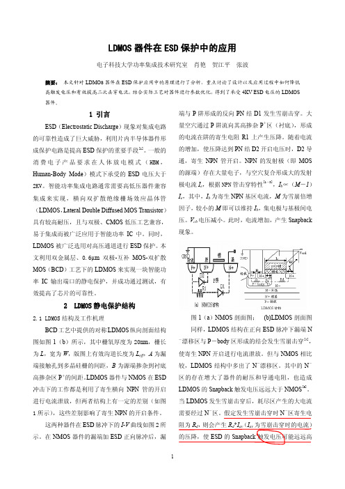
2 LDMOS静电保护结构2.1 LDMOS结构及工作机理BCD工艺中提供的对称LDMOS纵向剖面结构图如图1(b)所示,其中栅氧厚度为20nm,栅长为L,宽为W,版图上有效沟道长度为L eff,A为漏端接触孔到多晶硅栅的间距,B为源端掺杂到衬底高掺杂区P+的间距。
LDMOS器件与NMOS在ESD 冲击下的工作都是利用了寄生横向NPN管的开启进行电流泄放,但两者结构上有一定的差别(如图1所示),这些差别影响了寄生NPN的开启条件。
这两种器件在ESD脉冲下的I-V曲线如图2所示。
在NMOS器件的漏端加ESD正向脉冲后,漏端与P阱形成的反向PN结D1发生雪崩击穿。
CMOS集成电路ESD保护技术研究
CMOS集成电路ESD保护技术研究董培培;张海涛【摘要】介绍了 ESD 保护原理、测试方法及典型的 ESD 保护电路,针对2000V 的 HBM模型ESD 保护指标要求,采用 CSMC 0.5μm 25V(VGS)/25V (VDS)DPTM工艺模型和 GGMOS 器件进行了全芯片的 ESD 保护电路设计,并对 ESD 保护管的输出驱动级做了探索,在保证输出级 ESD 保护能力的同时,提高了输出端口的带负载能力。
鉴于 ESD 保护结构工艺移植性较差,保护性能与工艺密切相关的特点,结合具体版图设计实践,总结了 ESD 保护结构版图设计的通用原则。
这些原则旨在提高 ESD 保护结构的抗静电能力或提高 ESD 保护器件的工作可靠性,与具体的实现工艺无关。
流片后的 ESD 实验表明,设计的 ESD 保护结构可以承受2000V HBMESD 攻击。
%The principles,measurement methods and typical circuits of ESD Protection are introduced in this ing CSMC 0.5μm 25V(VGS)/25V(VDS)DPTMProcess and GGMOS devices,the ESD protection circuits of the whole chip are designed to achieve 2000V HBMESD protection ability,and output driver designed with ESD protection FETs is explored to raise the driving ability of output pin while keeping the ESD protection ability.Because technology portability of ESD protection circuits is bad and ESD protection ability is highly related with technology,combined with layout design practice,the general principles of ESD layout design are presented.The principles,regardless of technology,aim at raising the protection ability or reliability of ESD protection structure.The ESD experiment of the fabricated chip shows that the designed ESD protection structure can endure 2000V HBMESD attack.【期刊名称】《微处理机》【年(卷),期】2016(037)005【总页数】4页(P9-12)【关键词】ESD保护;GGMOS 器件;电路设计;版图设计;通用原则;工作可靠性【作者】董培培;张海涛【作者单位】中国电子科技集团公司第四十七研究所,沈阳 110032;中国人民解放军 95979 部队,辽宁,沈阳 110045【正文语种】中文【中图分类】TN4随着电路设计和制造工艺水平的发展,CMOS集成电路工艺尺寸不断缩小,单芯片集成度不断变大,且电路结构越来越复杂,极大提高了集成电路的性价比。
ESD保护结构设计
ESD保护结构设计静电放电会给电子器件带来破坏性的后果,它是造成集成电路失效的主要原因之一。
随着集成电路工艺不断发展,CMOS电路的特征尺寸不断缩小,管子的栅氧厚度越来越薄,芯片的面积规模越来越大,MOS管能承受的电流和电压也越来越小,而外围的使用环境并未改变,因此要进一步优化电路的抗ESD性能,如何使全芯片有效面积尽可能小、ESD性能可靠性满足要求且不需要增加额外的工艺步骤成为IC设计者主要考虑的问题。
ESD保护原理ESD保护电路的设计目的就是要避免工作电路成为ESD的放电通路而遭到损害,保证在任意两芯片引脚之间发生的ESD,都有适合的低阻旁路将ESD电流引入电源线。
这个低阻旁路不但要能吸收ESD电流,还要能箝位工作电路的电压,防止工作电路由于电压过载而受损。
在电路正常工作时,抗静电结构是不工作的,这使ESD保护电路还需要有很好的工作稳定性,能在ESD发生时快速响应,在保护电路的同时,抗静电结构自身不能被损坏,抗静电结构的负作用(例如输入延迟)必须在可以接受的范围内,并防止抗静电结构发生闩锁。
CMOS电路ESD保护结构的设计大部分的ESD电流来自电路外部,因此ESD保护电路一般设计在PAD 旁,I/O电路内部。
典型的I/O电路由输出驱动和输入接收器两部分组成。
ESD通过PAD导入芯片内部,因此I/O里所有与PAD直接相连的器件都需要建立与之平行的ESD低阻旁路,将ESD电流引入电压线,再由电压线分布到芯片各个管脚,降低ESD的影响。
具体到I/O电路,就是与PAD相连的输出驱动和输入接收器,必须保证在ESD发生时,形成与保护电路并行的低阻通路,旁路ESD电流,且能立即有效地箝位保护电路电压。
而在这两部分正常工作时,不影响电路的正常工作。
常用的ESD保护器件有电阻、二极管、双极性晶体管、MOS管、可控硅等。
由于MOS管与CMOS 工艺兼容性好,因此常采用MOS管构造保护电路。
CMOS工艺条件下的NMOS管有一个横向寄生n-p-n(源极-p型衬底-漏极)晶体管,这个寄生的晶体管开启时能吸收大量的电流。
深亚微米大容量PROM芯片ESD保护技术
深亚微米大容量PROM芯片ESD保护技术裴国旭;邓玉良;樊利慧;李晓辉;彭锦军【摘要】The ESD protection circuit design of PROMs is introduced based on 0. 18μm CMOS process. From a whole-chip’s point of view, the whole chip is protected in the round using multiple power and whole-chip ESD protection design. At the same time,the high voltage programming port’s ESD protection design is optimized. Final products pass the ESD testing and satisfy the project required.%从全芯片角度出发,采用多电源ESD架构和全芯片ESD设计,对整颗芯片提供全方位的ESD保护,介绍了基于0.18μm CMOS工艺设计的大容量PROM芯片的ESD设计技术。
同时,通过对高压编程引脚的ESD加固设计,提高了芯片的整体抗ESD能力。
最终产品ESD测试满足项目要求。
【期刊名称】《电子器件》【年(卷),期】2014(000)004【总页数】4页(P587-590)【关键词】静电放电(ESD);可编程只读存储器(PROM);全芯片【作者】裴国旭;邓玉良;樊利慧;李晓辉;彭锦军【作者单位】深圳市国微电子股份有限公司,广东深圳518057;深圳市国微电子股份有限公司,广东深圳518057;深圳市国微电子股份有限公司,广东深圳518057;深圳市国微电子股份有限公司,广东深圳518057;深圳市国微电子股份有限公司,广东深圳518057【正文语种】中文【中图分类】O472.8在IC(集成电路)产业中,静电放电ESD(Electro-Static Discharge)是影响IC芯片可靠性的主要因素之一,通过ESD保护电路设计,可以提高IC芯片的可靠性[1]。
功率集成中的ESD保护技术
静电放电(Electrostatic Discharge, ESD)是造成大多数的电子组件或电子系统受到过度电性应力(Electrical Overstress , EOS)破坏的主要因素。
这种破坏会导致半导体器件以及计算机系统等,形成一种永久性的毁坏,因而影响集成电路(Integrated Circuits, ICs)的电路功能,而使得电子产品工作不正常[1]。
据报道,集成电路35%的失效是由于ESD引起的,IC行业每年因ESD而带来的损失达几十亿美元。
早些时候,齐纳二极管是主要的保护器件。
随着半导体IC技术的发展以及ESD保护要求的提高,更多的结构被用来当做ESD保护,如BJT、MOS、SCR。
器件通常是由于ESD导致迅速产生的热量或者快速建立的强电场而遭到破坏。
在按比例缩小的CMOS工艺中,为了获得高速低功耗的电路性能,MOS器件具有更浅的结深,更薄的栅氧,轻掺杂漏区(LDD)结构以及slicided(硅化物掺杂)注入,而这些先进的工艺使得ESD保护结构的性能大大降低了[2]。
为了克服这些先进工艺对ESD保护结构的影响,同时不影响电路的性能,工艺上通常通过增加额外的掩模版(Mask)来解决,但这又大大增加了制造的成本。
因此,需要研究ESD 保护结构的保护机制,设计出性能优良的结构以降低成本。
芯片级ESD保护的本质有两种:运用低阻的泄放路径安全地消去瞬间大电流来防止硅的热损伤和金属的互联;将巨大的ESD电压脉冲嵌位在安全的电压值以防止介质的击穿[3]。
完整的ESD保护应该是对整个芯片的保护,关键点是在芯片上每一个pin脚与其他任一pin脚之间创建一条有效的泄放通道。
功率集成中的ESD保护分为低压保护、高压保护和接口电路的保护,本节将通过这三个方面一一阐述功率集成中ESD保护的基本内容与设计方法。
[1]ESD Protection in CMOS Integrated Circuits[2]Advanced Signal Processing, Circuits,and System Design Techniques for Communications[3]on-chip esd protection for IC1、低压保护为了防止ESD情况下内部电路形成大电流泄放通道,基本原则是采用低压半导体器件进行保护。
- 1、下载文档前请自行甄别文档内容的完整性,平台不提供额外的编辑、内容补充、找答案等附加服务。
- 2、"仅部分预览"的文档,不可在线预览部分如存在完整性等问题,可反馈申请退款(可完整预览的文档不适用该条件!)。
- 3、如文档侵犯您的权益,请联系客服反馈,我们会尽快为您处理(人工客服工作时间:9:00-18:30)。
Whole-Chip ESD Protection Design with Efficient VDD-to-VSS ESD Clamp Circuits for Submicron CMOS VLSIMing-Dou Ker,Senior Member,IEEEAbstract—A whole-chip ESD protection design with efficient VDD-to-VSS ESD clamp circuits is proposed to provide a real whole-chip ESD protection for submicron CMOS IC’s without causing unexpected ESD damage in the internal circuits.The efficient VDD-to-VSS ESD clamp circuit has been designed to provide a low-impedance path between the VDD and VSS power lines of the IC during the ESD-stress condition,but this ESD clamp circuit is kept off when the IC is under its normal operating condition.Due to the parasitic resistance and capacitance along the VDD and VSS power lines,the ESD-protection efficiency is dependent on the pin location on a chip.Therefore,an experimen-tal test chip has been designed and fabricated to build up a special ESD design rule for whole-chip ESD protection in a0.8- m CMOS technology.This whole-chip ESD protection design has been practically used to rescue a0.8- m CMOS IC product with a pin-to-pin HBM ESD level from the original level of0.5kV to become above3kV.Index Terms—ESD,ESD clamp circuit,snapback.I.I NTRODUCTIONE LECTROSTATIC DISCHARGE(ESD)protection hasbecome an important task on the reliability of CMOS IC’s.Especially in the submicron CMOS technologies,the advanced processes greatly degrade the ESD robustness of CMOS IC’s[1],[2].Besides the input or output ESD pro-tection circuits placed around the input or output pads,some unexpected ESD damages are still found in the internal circuits of CMOS IC’s beyond the input or output ESD protection circuits[3]–[11].Even the parasitic capacitance and resistance along the power lines of the IC also causes a negative impact on the ESD reliability of the CMOS IC[9]–[11].Since the ESD stress may have positive or negative voltage on an input(or output)pin with the VDD or VSS pins, respectively,grounded,there are four ESD-stress modes on an input(or output)pin[12].The four modes of ESD stresses on the input or output pins are illustrated in Fig.1.The input or output ESD protection circuits are therefore designed to bypass the ESD current from the stressed pin to the VDD or VSS pins. However,the ESD current may enter into any pin and go out from another pin of the IC.The ESD voltage may be applied Manuscript received February6,1998;revised September16,1998.This work was supported by the Elan Microelectronics Corp.(EMC),Science-Based Industrial Park,Hsinchu,Taiwan,R.O.C.The review of this paper was arranged by Editor C.-Y.Lu.The author is with the VLSI Design Division,Computer and Communica-tion Research Laboratories(CCL),Industrial Technology Research Institute (ITRI),Hsinchu,Taiwan310,R.O.C.(e-mail:mdker@.tw). Publisher Item Identifier S0018-9383(99)00265-8.Fig.1.Four modes of ESD stress on an input(or output)pin with respectto the grounded VDD or VSS pins.across any two pins of the IC and cause some unexpected ESDdamages in the internal circuits.Two additional ESD testingconditions,the pin-to-pin ESD stress and the VDD-to-VSSESD stress,had been specified in the ESD testing standardto verify the whole-chip ESD reliability[12].These twoadditional ESD testing conditions are illustrated in Fig.2(a)and(b).In these two ESD testing conditions,the internalcircuits are more vulnerable to ESD damage even if there areinput and output ESD protection circuits in the IC’s[13]–[15].In the pin-to-pin ESD stress of Fig.2(a),the ESD voltageacross the pins can be conducted into the VDD or VSS powerlines of the IC.The ESD current discharging paths in theIC under the pin-to-pin ESD stress condition are illustratedin Fig.3.In Fig.3(a),a positive ESD voltage is applied toan input pin with some output pin relatively grounded,butboth the VDD and VSS pins arefloating.Before the positiveESD voltage on the input pad is discharged through the inputprotection diode Dn1,the ESD current is conducted into thefloating VDD power line through the forward-biased diodeDp1in the input ESD protection circuit.The ESD current istherefore conducted into the internal circuits through the VDDpower line and discharged through the internal circuits to VSS.In Fig.3(b),a negative ESD voltage is applied to an outputpin,while some input pin is grounded but the VDD and VSSarefloating.Such negative ESD voltage is also conducted intothe internal circuits through the VSS power line of the IC.In the VDD-to-VSS ESD testing condition of Fig.2(b),theESD voltage is directly applied to the VDD pin with the VSS 0018–9383/99$10.00©1999IEEE(a)(b)Fig.2.Two additional ESD-testing conditions to verify the whole-chip ESD reliability.(a)The pin-to-pin ESD stress:the ESD voltage is applied to an input (or output)pin while all other input and output pins are grounded but the VDD and VSS pins are floating.(b)The VDD-to-VSS ESD stress:the ESD voltage is directly applied to the VDD pin with the VSS pin grounded but all input and output pins are floating.pin grounded but all the input and output pins are floating.The ESD current discharging path in this VDD-to-VSS ESD stress condition is illustrated in Fig.4.Because the internal circuits are often drawn with the minimum device dimensions and layout spacings to save layout area,the internal circuits are very vulnerable to the ESD current.The ESD damages in the internal circuits are difficult to be found by only measuring the leakage current on the input or output plex failure analyzes with full function verification are often required to find the failure location.In order to clamp the ESD overstress voltage across the power lines,the gate-grounded NMOS was used as the ESD clamp device between the VDD and VSS power lines [7]–[9],[14],[15],as shown in Fig.5.In the pin-to-pin or the VDD-to-VSS ESD stresses,the ESD voltage across the VDD and VSS power lines of the IC is clamped by the gate-grounded NMOS in its snapback-breakdown region.Because the ESD current is discharged through the gate-grounded NMOS,this gate-grounded NMOS has to be drawn with a larger device dimension to protect itself.However,the device dimensions and layout spacings of the internal circuits are further reduced in the scaled-down CMOS technology.During the pin-to-pin or the VDD-to-VSS ESD stresses,the internal circuits with minimum device dimensions and spacings are easily damaged by the ESD overstress voltage before the gate-grounded NMOS with larger device dimension is broken down to bypass the ESD current.So,to really protect all the circuits in an IC,a suitable ESD clamp circuit has to be placed between the VDD and VSS power lines of the IC to clamp the ESD overstress voltage across the power lines[16]–[20].(a)(b)Fig.3.ESD current paths through the IC under the pin-to-pin ESD testing condition.(a)A positive ESD voltage is applied to some input pin while another output pin is grounded.(b)A negative ESD voltage is applied to some output pin while another input pin isgrounded.Fig.4.ESD-current discharging path through the IC under the VDD-to-VSS ESD testing condition.However,when more functions and circuits are integrated into a single chip,the die size of a CMOS IC is enlarged with longer VDD and VSS power lines surrounding the whole chip.The longer power lines can cause a delay to discharge ESD current through the desired ESD clamp circuit in the CMOS VLSI [9]–[11].This causes that the ESD levels of different pins are dependent on their pin locations in the chip.If the ESD-stressed pin is far from the desired VDD-to-VSS ESD clamp circuit,the ESD current can be still conducted into the internal circuits to cause some unexpected ESD damages in the internal circuits.In this paper,the dependence of ESD level on different pin location is investigated by an experimental test chip.Therefore,a whole-chip ESD protection design with efficientKER:WHOLE-CHIP ESD PROTECTION DESIGN175Fig.5.Prior art of VDD-to-VSS ESD protection design by using a gate-grounded NMOS as the ESD clamp device between the VDD and VSS powerlines.Fig.6.An effective VDD-to-VSS ESD protection design to achieve the whole-chip ESD protection.VDD-to-VSS ESD clamp circuits is demonstrated to fully protect a submicron CMOS IC without causing unexpected ESD damage in the internal circuits[21].This whole-chip ESD protection design has been successfully implemented in a mass-production consumer IC to improve its human-body-model(HBM)ESD level from0.5to above3kV in all ESD testing conditions,but without increasing the die size of the IC product.II.E FFICIENT VDD-T O-VSS ESD C LAMP C IRCUITA.Concept of the Efficient ESD Clamp CircuitTo efficiently clamp the ESD voltage across VDD and VSS power lines before the internal circuits are damaged,an ESD-transient detection circuit is used to turn on the VDD-to-VSS ESD-clamping NMOS,as illustrated in Fig6.The ESD-transient detection circuit is designed to detect the ESD event and sends a control voltage to the gate of the ESD-clamping NMOS.Because the ESD-clamping NMOS is turned on by a positive gate voltage rather than by the drain snapback-breakdown,the NMOS can be turned on at lower voltage to bypass the ESD current before the internal circuits are damaged by the ESD overstress voltage.In the pin-to-pin ESD stress condition,as shown in Fig.6,the ESD current is diverted from the input pin into thefloating VDD power line. Thefloating VSS power line is initially biased at a ground level through the parasitic diode Dn2in the output NMOS with a grounded output pin.Therefore,the ESD-transient detection circuit is biased by the ESD energy and turns on the ESD-clamping NMOS to provide a low-impedance path between the VDD and VSS power lines to bypass ESD current.Thus,the ESD current can be efficiently discharged through the forward-biased diode Dp1,the ESD-clamping NMOS,and the diode Dn2.The devices operating in the forward-biased conditions can sustain much higher ESD current than they operating in the reverse-biased breakdown conditions.But,when the IC is in the normal operating condition with the power supplies,this ESD-clamping NMOS has to be kept off to avoid power loss from VDD to VSS.B.Realization of the ESD Clamp CircuitTo realize the aforementioned ESD-transient detection func-tion,as to achieve the desired operations.Initially,thenodesto176IEEE TRANSACTIONS ON ELECTRON DEVICES,VOL.46,NO.1,JANUARY1999Fig.7.Realization of the efficient VDD-to-VSS ESD clamp circuit.(a)(b)Fig.8.Schematic voltage waveform on the node V G in Fig.7under(a)theESD-stress condition and(b)the normal power-on condition.rise up the voltage level of10ns[12].The voltage level ofs).Due to the delay of the voltageincrease on the node)of the ESD-clamping NMOS can bemainly adjusted by theKER:WHOLE-CHIP ESD PROTECTION DESIGN177(a)(b)Fig.11.Turn-on verification on the proposed VDD-to-VSS ESD clamp circuit in the ESD-stress condition:(a)the experimental setup used to simulate the ESD-stress condition and (b)the measured voltage waveform on the VDD power line.as can follow the VDD voltage in timeto keeptheat a voltage level of 0V.So,the ESD-clamping NMOS is guaranteed to be kept off when the IC is under the VDD power-on condition or in the normal operating conditions.The schematic voltage waveformofm CMOSprocess are chosenask,andof.Theresistorm/mCMOS(a)(b)Fig.12.Turn-on verification on the proposed VDD-to-VSS ESD clamp circuit in the VDD power-on condition:(a)the experimental setup used to simulate the normal VDD power-on condition and (b)the measured voltage waveform on the VDD power line.process.Them CMOS process,the pulse heightof the ramp voltage is set as 10V to monitor the voltage on thenode178IEEE TRANSACTIONS ON ELECTRON DEVICES,VOL.46,NO.1,JANUARY 1999dimension of the ESD-clamping NMOS is strongly dependent on the required ESD level and the specified layout area of the IC.For an IC product with a higher ESD specification,it needs a larger ESD-clamping NMOS to protect the internal circuits of the IC and itself.C.Turn-On Verification of the ESD Clamp CircuitThe VDD-to-VSS ESD clamp circuit had been fabricated in a0.6-mCMOS process.With a gate voltage of 10V,the ESD-clamping NMOS can be quickly triggered into its snapback region to bypass the ESD current from VDD to VSS power lines.But,an NMOS device with a higher gate voltage or a longer turn-on timeoften causes alower (secondary breakdown current)value [22],[23],because a shallow current flows through the channel surface of the NMOS.Thus,the ESD-clamping NMOS were designed with a large device dimension of 8000/0.8in [16]to sustain an HBM ESD level of 3kV.In the advanced submicron CMOS technology with silicided diffusion and LDD structure,the ESD-clamping NMOS has better to be drawn with the silicide-blocking mask,the ESD-implant mask,and a wider layout spacing from the drain contact to its ploy gate to improve its ESD-sustained level.In other design to increase the ESD-sustained level of the ESD-clamping NMOS,an N-well resistor was added into the drain region of the ESD-clamping NMOS in the VDD-to-VSS ESD clamp circuit [24].In order to avoid the gate-driven effect [23]which causes a low ESD level on the NMOS device,and also to reduce the device dimension and layout area for the ESD-clamping device between VDD and VSS power lines,a substrate-triggering technique has been applied to trigger on a field-oxide device to provide a more area-efficient design for VDD-to-VSS ESD clamp circuit [25].To verify the action of the VDD-to-VSS ESD clamp circuit in the normal VDD power-on condition,an experimental setup is shown in Fig.12(a).A ramp voltage with a rise time of 0.1ms and a high-level voltage of 5V is applied to the VDD power line with the VSS power line grounded to simulate the VDD power-on condition.The voltage waveform on the VDD power line is monitored and shown in Fig.12(b),where the voltage waveform is still remained as a ramp voltage without any degradation on the waveform.So,the ESD-clamping NMOS in the VDD-to-VSS ESD clamping circuit has been verified to be indeed kept off in the VDD power-on condition.This ESD clamping circuit can be always kept off while the IC is in the normal operating condition with the static VDD power supply.III.W HOLE-C HIP ESD P ROTECTION D ESIGNThe operation of pin-to-pin ESD protection with the efficient VDD-to-VSS ESD clamp circuit has been explained in Fig.6.With suitable design on the ESD-transient detection circuit,the ESD-clamping NMOS can provide an effective discharging path between VDD and VSS power lines to bypass ESD current away from the internal circuits of the IC.However,the modem VLSI (or ULSI)often has a very large die size,which has much longer VDD and VSS power lines to surround the whole chip and to connect the I/O circuits.Such longer power lines had been reported to have a negative impact on the ESD protection of IC’s [9]–[11].The negative impact on the pin-to-pin ESD protection owing to the longer VDD and VSS power lines is illustrated in Fig.13,where the VDD-to-VSS ESD clamp circuit is placed far from the stressed input and output pads.The longer VDD and VSS power lines generally causehigher series resistance()along the power lines or a larger VDD-to-VSS parasitic capacitance()across the power lines.Theparasitic,and along the VDD and VSS power lines contribute a time delay to limit the ESD current discharging through the ESD-clamping NMOS.Theequivalentparasitic,and along the VDD and VSS power lines are strongly dependent on the location of theKER:WHOLE-CHIP ESD PROTECTION DESIGN179Fig.13.Schematic diagram to show the spacing effect on the ESD protection of a chip due to the parasitic resistance and capacitance along the VDD and VSS powerlines.Fig.14.Test chip design to investigate the pin-location spacing effect on the ESD-protection performance with the efficient VDD-to-VSS ESD clamp circuit.stressed pad and the grounded pad in the IC.If the VDD-to-VSS ESD clamp circuit is located too far from the stressed pad and the grounded pad,as shown in Fig.13,the speed and efficiency to bypass the ESD current through the VDD-to-VSS ESD clamp circuit is seriously delayed and degraded by the parasitic resistance and capacitance along the power lines.Some ESD current is still discharged through the internal circuits and causes some ESD damages on the internal circuits.So,the pins of the IC may have different ESD levels,even if the pins have the same ESD protection circuits.The stressed pin has a higher ESD level if the stressed pin is closer to the VDD-to-VSS ESD clamp circuit.Therefore,a special design rule to specify the spacing from the input or output pins to the VDD-to-VSS ESD clamp circuit for effective whole-chip ESD protection has to be established.An experimental test chip has been designed to investigate the pin-location spacing effect on the ESD-protection perfor-mance with the efficient VDD-to-VSS ESD clamp circuit.A schematic diagram of the experimental test chip to investigate the spacing effect is shown in Fig.14.The VDD-to-VSS ESD clamp circuit is located on the VDD pad in the center of Fig.14and a VSS pad is adjacent to this VDD pad.The output pads are located at the left-hand part of Fig.14with different spacings to the VDD-to-VSS ESD clamp circuit.Ateach output pad,the output PMOS and NMOS devices have the same device dimension()of 150/1.2(m,and the spacing between the anode and cathode of the diodes is2.4m).Theresistors.The metalwidth of both VDD and VSS power lines is drawn as30m CMOStechnology with LDD process.The HBM ESD testing results are measured in Figs.15and 16to verify the spacing effect on the ESD-protection efficiency.In the HBM ESD test,the ESD pulse is applied to the stressed pin with three zaps per stress voltage level [12].After the ESD stress,the test chip is inspected by the full function test including the leakage currents on the input,output,and VDD pins to judge whether the test chip is damaged by the applied ESD pulse.In Fig.15(a),it shows the dependence of the input PS-mode180IEEE TRANSACTIONS ON ELECTRON DEVICES,VOL.46,NO.1,JANUARY1999(a)(b)Fig.15.Experimental results to verify the spacing effect on the HBM ESD robustness of the input pin in (a)the PS-mode and (b)the ND-mode,ESD-stress conditions.ESD level on the spacing from the input pad to the VDD-to-VSS ESD clamp circuit.The ESD level of the input pad is significantly increased when the input pad is closer to the VDD-to-VSS ESD clamp circuit.The PS-mode ESD level of the input pad is improved from the original level about 2.5kV to more than 4kV,while the location spacing from the input pad to the ESD clamp circuit is below2000m.The shorter distance from the inputpad to the VDD-to-VSS ESD clamp circuit leads to a much higher ESD level of the input pad.This provides a new ESD protection concept to improve ESD level of the input pin by only using the efficient VDD-to-VSS ESD clamp circuit but without increasing the device dimensions in the input ESD protection circuits.The pin-to-pin ESD protection performance is measured in Fig.16(a)and (b).In Fig.16(a)and (b),a positive (negative)ESD voltage is applied to some input pin of Fig.14,while(a)(b)Fig.16.Experimental results of the spacing effect on the HBM ESD robustness of the pin-to-pin ESD reliability from an ESD-stressed input pin to another relatively grounded output pin.(a)A positive ESD voltage and (b)a negative ESD voltage is applied to an input pin while another output pin is grounded,but other pins including the VDD and VSS pins are all floating.another output pin is grounded but the other pins including the VDD and VSS pins are all floating,to investigate the spacing effect on the pin-to-pin ESD protection with the efficient VDD-to-VSS ESD clamp circuit.In Fig.16(a),the positive pin-to-pin ESD level is increased greater than 3.5kV while the spacing between the stressed input pad and the grounded output pad is less than3000m.By using theefficient VDD-to-VSS ESD clamp circuit,the pin-to-pin ESD level can be significantly improved if the spacing between the stressed pin and the grounded pin is not too large.To provide a 3-kV pin-to-pin ESD reliability for the CMOS IC with thepower line width of30m CMOS process,the VDD-to-VSS ESD clamp circuit has to be repeatedly inserted between the VDD and VSS power lines in every distance of3000KER:WHOLE-CHIP ESD PROTECTION DESIGN181Fig.17.Schematic diagram to show the concept of whole-chip ESD pro-tection design with four efficient ESD clamp circuits between the VDD andVSS power lines in an CMOS chip.surrounding the whole chip,and the shorter distance of everyrepeat of the VDD-to-VSS ESD clamp circuit can lead to amuch higher pin-to-pin ESD protection.Through the detailedanalysis and experimental investigation,a special ESD designrule for whole-chip ESD protection with efficient VDD-to-VSS ESD clamp circuits has been established in a0.8-m CMOS ICproduct.In the original ESD design of this IC product,twogate-grounded NMOS’s(182IEEE TRANSACTIONS ON ELECTRON DEVICES,VOL.46,NO.1,JANUARY1999Fig.19.Microphotograph of a0.8- m CMOS IC product using the proposed whole-chip ESD protection design withfive VDD-to-VSS ESD clamp circuits(indicated by the arrows).location is not found in the internal circuits of the failedIC.So,the internal circuits of this IC product can be fullyprotected against ESD damage by this proposed whole-chipESD protection design with suitable spacing distribution to addthe efficient VDD-to-VSS ESD clamp circuits into the chip.V.C ONCLUSIONBased on them to providea3-kV pin-to-pin HBM ESD level in a0.8-m.Such a whole-chipESD protection design has been successfully applied to rescuethe ESD level of an IC product in a0.8-KER:WHOLE-CHIP ESD PROTECTION DESIGN183[12]EOS/ESD Standard for ESD Sensitivity Testing,EOS/ESD Association,Inc.,New York,1993.[13] C.Cook and S.Daniel,“Characterization of new failure mechanismsarising from power-pin ESD stressing,”in Proc.EOS/ESD Symp.,1993, pp.149–156.[14]X.Guggenmos and R.Holzner,“A new ESD protection concept forVLSI CMOS circuits avoiding circuit stress,”in Proc.EOS/ESD Symp., 1991,pp.74–82.[15]N.Maene,J.Vandenbroeck,and L.V.D.Bempt,“On chip electro-static discharge protections for inputs,outputs,and supplies of CMOS circuits,”in Proc.EOS/ESD Symp.,1992,pp.228–233.[16]R.Merrill and E.Issaq,“ESD design methodology,”in Proc.EOS/ESDSymp.,1993,pp.233–237.[17]S.Dabral,R.Aslett,and T.Maloney,“Core clamps for low voltagetechnologies,”in Proc.EOS/ESD Symp.,1994,pp.141–149.[18] E.R.Worley,R.Gupta,B.Jones,R.Kjar,C.Nguyen,and M.Tennyson,“Submicron chip ESD protection schemes which avoid avalanching junctions,”in Proc.EOS/ESD Symp.,1995,pp.13–20.[19]T.Maloney and S.Dabral,“Novel clamp circuits for IC power supplyprotection,”in Proc.EOS/ESD Symp.,1995,pp.1–12.[20]G.D.Croft,“Transient supply clamp with a variable RC time constant,”in Proc.EOS/ESD Symp.,1996,pp.276–279.[21]M.-D.Ker and S.-C.Liu,“Whole-chip ESD protection design forsubmicron CMOS VLSI,”in Proc.IEEE Int.Symp.Circuits and Systems, 1997,pp.1920–1923.[22] C.Duvvury and C.Diaz,“Dynamic gate coupling of nMOS for efficientoutput ESD protection,”in Proc.IRPS,1992,pp.141–150.[23]J.-Z.Chen,A.Amerasekera,and C.Duvvury,“Design methodologyfor optimizing gate driven ESD protection circuits in submicron CMOS processes,”in Proc.EOS/ESD Symp.,1997,pp.230–239.[24] E.Worley,B.Jones,and R.Gupta,“ESD protection for submicronCMOS circuits,”U.S.Patent5440162,Aug.1995.[25]M.-D.Ker,“Area-efficient VDD-to-VSS ESD protection circuit,”U.S.Patent5744842,Apr.1998.Ming-Dou Ker(S’92–M’94–SM’97)was born inTaiwan,R.O.C.,in1963.He received the B.S.degree from the Department of Electronics Engi-neering,and the M.S.and Ph.D.degrees from theInstitute of Electronics,National Chiao-Tung Uni-versity(NCTU),Hsinchu,Taiwan,in1986,1988,and1993,respectively.In1994,he joined the Computer and Commu-nication Research Laboratories(CCL),IndustrialTechnology Research Institute(ITRI),Hsinchu,as aCircuit Design Engineer.Currently,he is a Depart-ment Manager in the VLSI Design Division of CCL/ITRI.He is also currently a Research Advisor in the Integrated Circuits and Systems Laboratory,NCTU. In thefield of ESD/latchup in CMOS technology,he has published more than 60technical papers in the international journals and conferences.He has15 U.S.patents on the CMOS ESD protection circuits.He has been invited to teach ESD protection design more than30times by the IC/semiconductor companies in the Science-Based Industrial Park,Hsinchu.Dr.Ker was included in the1998Who’s Who in the World.。