流量计使用指南说明书
ALICAT 流量计 流量控制器 简易操作指南说明书

针脚号DB15 DB15K DB9/DB9M 8针mini-DIN 6针工业接头 1 接地 不接 4-20mA 输出 4-20mA 输出 电源正 2 模拟输出 模拟输出 第2路模拟出 第2路模拟出 TX(+)发送 3 接地 不接 RX(-)接收 RX(-)接收 RX(-)接收 4 不接 不接 模拟输入 模拟输入 模拟输入 5 电源正 接地 TX(+)发送 TX(+)发送 接地 6 不接 不接 0-5V 输出 0-5V 输出 模拟输出 7 不接 电源正 电源正 电源正 8 模拟输入 模拟输入 接地 接地 9 接地 第2路模拟出 接地 10 接地 不接 11 第2路模拟出 接地 12 不接 接地 13 RX(-)接收 RX(-)接收 14 接地 TX(+)发送 15 TX(+)发送 接地ALICAT 流量计/流量控制器简易操作指南1.外观概览2.针脚定义流量方向比例阀 背光灯开关功能键 屏幕电源插孔通讯线接口NPT 螺纹接口安装螺孔8-32 UNC3.功能按键3.2屏幕背光灯:按屏幕下方红色ALICAT 商标 可打开/关闭屏幕背光灯。
3.3切换输入信号源:进入菜单Menu ,在Control – ADV Control – SETPT Source 中可切换数字信号控制或模拟信号控制。
Serial/Front Panel 即数字信号/面板控制,Analog 即模拟信号。
3.4切换控制对象:在Control – ADV Control – Loop Setup – Loop VAR 中可切换控制对象为质量流量、体积流量或压力。
默认为质量流量。
3.5调节PID 增益:在Control – ADV Control – Loop Setup – Loop Gains 中可调节PID 增益值。
PID 值会影响控制器的稳定性和响应速度。
3.6输入设定值:在对应的信号模式下可分别使用数字信号、面板按键、模拟信号来输入设定值。
E+H质量流量计中文说明书

BA057D/06/zh/06.0550098468PROline promass80科氏力质量流量测量系统操作指南简明操作指南该操作指南指导您对测量仪表进行快速简便的设定安全指南第页7安装第页31接线第页13第页23显示和操作单元使用“快速设定”进行调试QUICK SETUP ()第页50您可使用“快速设定”菜单对测量仪表进行快速、方便的调试,使用现场显示设置基本功能,如显示语种、测量变量、变量单位、信号种类等以下功能可单独实现(如需要):-零点校正-密度校正-电流输出设置(有源无源)QUICK SETUP()/用户专用设置复杂测量操作需要某些附加功能,您可以借助于功能矩阵进行设置,并将其用户化以满足您的测量过程需要提示:所有功能的详细描述,请查阅“”手册功能描述提示:如在调试后或操作过程中出现故障,请启动故障诊断,见第页诊断清单,找出故障原因以及相应的排障措施。
61第页52主显示页快速设定初始化质量流量E E语言预设定体积流量标准体积流量密度温度退出质量流量单位体积流量单位密度单位温度单位累积器单位累积器单位参考密度单位参考密度值设定其他单位?选择系统单位是否测量模式选择输出模式电流输出1电流输出2频率/脉冲输出退出操作模式频率脉冲电流对应变量电流对应变量电流范围电流范围0/4mA 对应值20mA 对应值时间常数失效模式0/4mA 对应值20mA 对应值时间常数频率对应变量频率上限频率下限频率上限值输出信号时间常数脉冲对应变量脉冲当量脉冲宽度输出信号失效模式失效模式设定其他输出?是否自动设定显示是否自动设定显示参数失效模式标准体积流量单位快速设定提示:快速设定菜单的详细信息,尤其是不带现场显示仪表的操作,请查阅第页。
50·在参数输入过程中按ES C 键,返回QU I CK S ET U P CO MM I SS I O N ,所设定的参数值有效·在进行以下快速设定前必须启动“快速设定”功能·①对当前设定中未设置的单位进行选择,在相应的流量单位中选择质量流量、体积流量、标准体积流量单位·②保持“Y E S ”选项,直到所有单位设置完成“N O ”选项表示没有需要设置的单位·③只对当前设定中未设置的输出进行选择·④保持“Y E S ”选项,直到所有输出设置完成“N O ”选项表示没有需要设置的输出·⑤“参数化显示”包含下列基本设定/出厂设定:YE S :第一行=质量流量;第二行=累积量1;NO :保持现有的设定提示:正确使用安装、调试和操作操作安全返修安全规范和图标名称变送器铭牌传感器铭牌标志,一致性声明注册商标收货确认、运输和储存收货确认运输储存安装条件尺寸安装位置安装方向伴热保温进出口直管段振动限流安装指南旋转变送器外壳墙挂式变送器安装旋转现场显示模块安装后的检查分离型仪表的连接传感器的连接电缆规格测量单元的连接变送器的连接端子分配连接防护等级接线后的检查显示和操作单元功能矩阵简明操作指南注意事项激活编程模式禁止编程模式错误信息通信操作选项仪表和过程变量1.安全指南.标识...7....................................................2 (9)1.1...............................................................71.2..........................................71.3...............................................................71.4.....................................................................81.5. (8)2.1 (9)2.1.1...................................................92.1.2.................................................102.2CE ....................................102.3.............................................................113.1.. (13)3.1.1....................................................133.1.2............................................................133.1.3............................................................143.2. (14)3.2.1.............................................................143.2.2....................................................143.2.3....................................................163.2.4............................................................183.2.5............................................................193.2.6.............................................193.2.7............................................................193.2.8............................................................193.3 (20)3.3.1.........................................203.3.2......................................213.3.3.......................................223.4......................................................224.1. (23)4.1.1..............................................234.1.2....................................................244.2. (25)4.2.1.............................................254.2.2....................................................274.2.3HART .................................................284.3......................................................294.4....................................................305.1.............................................315.2.. (32)5.2.1......................................................335.2.2............................................335.2.3............................................335.3.......................................................345.4. (35)5.4.1....................................................355.4.2 (36)仪表3.................................................................134...................................................................235...................................................................31安装接线操作目录5.4.3/HART .................375.4.4/..................................436.1...................................................496.2. (49)6.2.1..........................................496.2.2....................................506.2.3.................................................526.2.4.................................................546.2.51/.............................556.2.62/............................566.2.7..............................579.1............................................619.2............................................629.3............................................679.4.............................699.5..............................................709.6........................................................729.7.............................739.8....................................779.9...................................................78.........................................................................................................................................................................................................................................................................................................................................................................................................................................................................................................................................................................................................................................................................................通用型普通应用型指令仪表状态错误信息功能检测调试测量仪表上电快速设定“调试”零点校正密度校正电流输出:有源无源电流输出:有源无源吹扫和压力监测连接故障诊断指南系统错误信息过程错误信息无显示信息的过程错误输出响应错误备品备件更换和安装印刷线路板仪表保险丝的更换软件版本6.................................................................497................................................................588................................................................599.......................................................6110.....................................................调试维护附件故障诊断技术参数一览应用功能和系统设计输入输出供电性能特性操作条件机械结构用户接口认证订货信息附件相关文件尺寸;墙挂式变送器尺寸:不锈钢现场变送器技术参数8110.18110.1.18110.1.28110.1.38110.1.48310.1.58310.1.68410.1.78810.1.89710.1.910010.1.1010010.1.1110010.1.1210110.1.1310110.210210.310210.4(P r om a s s F ,M ,A,H ,I )....10310.5尺寸:分离型(P r om a s s E )10310.6尺寸:分离伴热型10310.7尺寸:高温型(一体化型)10410.8尺寸:高温型(分离型)10410.9尺寸:Pr o ma ss F 10510.10尺寸:Pr o ma ss M 11510.11尺寸:Pr o ma ss E 12910.12尺寸:Pr o ma ss A 13810.13尺寸:Pr o ma ss H 14410.14尺寸:Pr o ma ss I 146尺寸:分离型.....................................................................................................................................................................................................................................................................................................................................................................................1安全指南1.1正确使用PR Ol in e P ro ma s s 8系列流量计用于测量液体和气体的质量流量,同时也可测量流体密度和温度。
FLS F6.60电磁流量计安全说明说明书
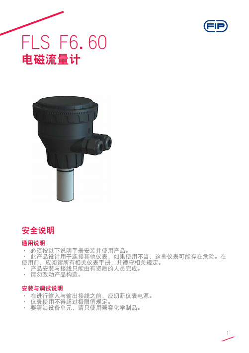
FLS F6.60电磁流量计安全说明通用说明• 必须按以下说明手册安装并使用产品。
• 此产品设计用于连接其他仪表,如果使用不当,这些仪表可能存在危险。
在使用前,应阅读所有相关仪表手册,并遵守相关规定。
• 产品安装与接线只能由有资质的人员完成。
• 请勿改动产品构造。
安装与调试说明• 在进行输入与输出接线之前,应切断仪表电源。
• 仪表使用不得超过极限值规定。
• 要清洁设备单元,请只使用兼容化学制品。
包装清单请核实产品完整,并且没有任何损坏。
必须包含以下物品:• F6.60 电磁流量计• F6.60 电磁流量计说明手册• 带接口软件的 USB 笔式驱动器• 用于仪表/电脑接口的 USB 电缆说明新型 FLS F6.60 是一种无移动机械部件的流量计,可以用于测量具有导电性的匀质污染液体。
F6.60可以提供三种不同的选项:与FLS流量监视器相连的频率输出,长距离传输和PLC连接的4-20mA输出,以及新的可自由设置的体积脉冲输出。
F6.60插入型电磁流量计装有USB接口和完整专用软件(可从FLS网站免费下载),可以通过电脑按照特殊的安装要求轻松设置所有参数(例如满刻度和截止参数)。
此特定设计可以在DN15(0.5”) - DN600(24”)的宽范围管道尺寸内实现精确的流量测量。
技术数据通用• 管道尺寸范围:DN15 至 DN600(0.5”至 24”)• 最大流量范围:0.05 - 8m/s(0.15 - 26.24 ft./s)• 满量程:8 m/s (26.24 ft/s)• 线性:读数的± 1% + 1.0 cm/s• 可重复性:读数的± 0.5%• 外壳:IP65• 材料:- 箱体:PC/ABS- 垫片:EPDM• 焊接材料:- 传感器本体:316L SS/PVDF;316L SS/PEEK;CuNi合金/PVDF- O形圈:EPDM或FPM- 电极:316L SS 或 CuNi 合金电气• 电源:- 12 - 24VDC±10% 稳压(逆极性和短路保护)- 最大电流:消耗量:250 mA- 保护性接地:< 10 Ω• 电流输出:- 4-20 mA,隔离- 最大环路阻抗:800Ω(24VDC)- 250Ω(12VDC)- 正流量指示或负流量指示• 固态继电器输出:- 用户可选择:最小值警报、最大值警报、体积测定、脉冲输出、窗口警报、关闭- 光隔离,50mA最大漏电流,24VDC最大上拉电压- 最大脉冲/分钟:300- 迟滞:用户可选择• 开路集电极输出(频率):- 类型:开路集电极NPN- 频率:0 – 800 Hz- 最大上拉电压:24 VDC- 最大电流:50 mA,限流- 与FLS M9.02、M9.03、M9.50兼容• 开路集电极输出(方向):- 类型:开路集电极NPN- 最大上拉电压:24 VDC- 最大电流:50mA,限流- 电流方向:0 VDC 箭头方向+ VDC 箭头反向环境• 存储温度:-30°C - +80°C(-22°F - 176°F)• 环境温度:-20°C - +70°C(-4°F - 158°F)•相对湿度:0 - 95%(无结露)• 液体条件:- 均质液体、糊剂或料浆,还有固体成份- 最小电导率:20 μS- 温度:PVDF底部版本:-10°C - +60°C(14°F - 140°F)PEEK底部版本:-10°C - +150°C(14°F - 302°F)• 最大工作压力:- 16 bar @ 25°C (232 psi @ 77°F)- 8.6 bar @ 60°C (124 psi @ 140°F)标准和认证•按照ISO 9001要求制造•按照ISO 14001要求制造•CE•RoHS合规性•GOST R尺寸A 传感器本体B F6.60 电磁流量计1 O形圈(EPDM 或 FPM)2 传感器本体(316L SS 或 CuNi)3 隔离板(PVDF 或 PEEK)4 电极(316L SS 或 CuNi)5 电缆填料盖6 管件内安装使用的 ABS 端帽7 电子盒安装管道位置• 图1中显示的六个最普通的安装配置有助于在管道中为转轮式流量传感器和电磁流量传感器选择最佳位置。
流量计说明书

流量计说明书流量计是一种用来测量液体或气体在管道中流动速度的仪器,它具有精确测量、稳定性好、使用方便等特点。
本说明书将详细介绍流量计的使用方法、操作步骤以及注意事项,以便用户能够正确、有效地使用流量计。
一、产品简介流量计是一种基于流体动力学原理制作而成的仪器,它采用了先进的传感技术和自动化控制技术,能够准确、精确地测量流体的流速。
流量计是工业生产过程中广泛应用的一种仪器,它可以帮助用户实现流体管道的监测、控制和调节,从而提高生产效率。
二、流量计的使用方法1. 准备工作在使用流量计之前,需要确认流量计的型号、规格和安装位置是否符合要求。
同时,还需检查流量计的外观是否完好,有无损坏或污垢。
如果有损坏或污垢,应及时清洗或更换。
2. 安装流量计将流量计按照要求正确安装在管道上,并注意连接的紧固程度。
安装时应注意避免弯曲、损坏或挤压传感器。
3. 接通电源将流量计的电源线连接到电源插座上,并确保电源线连接稳固。
在接通电源之前,要阅读并理解流量计的电气连接图,确保正确连接。
4. 设置参数根据实际需要,通过流量计的操作界面设置相应的参数,包括流速单位、报警值、输出信号等。
在设置参数时,应仔细阅读产品说明书,确保操作正确。
5. 启动流量计接通电源后,按照流量计的操作说明进行启动操作。
启动时要注意阀门的开关和流量计的指示灯状态,确保流量计正常工作。
6. 监测流量启动流量计后,可以通过液晶显示屏或其他指示装置实时监测流量变化。
在监测过程中,应注意观察流量计的指示,避免超过量程或出现异常情况。
7. 停止使用在使用完毕后,应及时停止流量计的运行,关闭电源。
同时进行相应的维护工作,保证流量计的正常使用寿命。
三、注意事项1. 使用环境:流量计适用于室内使用,不适宜在潮湿、高温或极寒的环境中使用。
2. 清洁保养:定期检查流量计的工作状态,如发现异常情况应及时清洁或进行维修。
避免污水、灰尘等污染物对流量计的影响。
3. 防雷保护:在雷电天气时,应及时切断流量计的电源,以免被雷击损坏。
电磁流量计说明书

电磁流量计操作使用说明书目录一、操作指南1.基本设置 (5)1.1 流量单位 (5)1.2 流量显示分辨率 (5)1.3 总量单位 (5)1.4 总量显示分辨率 (5)1.5 阻尼时间(s) (5)2.信号处理设置 (6)2.1 刻度流量 (6)2.2 小信号切除% (6)3.脉冲输出设置 (7)3.1 频率上限 (7)3.2 脉冲当量 (7)3.3 脉冲宽度 (7)3.4 脉冲电平 (8)3.5 频率/脉冲输出选择 (8)4.RS485输出设置 (8)4.1 通讯协议选择 (8)4.2 波特率 (8)4.3 数据位 (9)4.4 校验方式 (9)4.5 设备地址 (9)5.累计管理 (9)5.1 清累计 (9)5.2 预置累计 (9)6.仪表校准 (10)6.1 4mA校准 (10)6.2 20mA校准 (10)6.3 零点校准 (10)7.工厂设置 (11)7.1 传感器口径 (11)7.2 转换器系数 (11)7.3 传感器系数 (12)7.4 励磁频率 (12)7.5 低流量报警开关 (12)7.6 高流量报警开关 (12)7.7 空满管检测开关 (12)7.8 高流量报警点% (13)7.9 低流量报警点% (13)7.10 RS485功能开关 (13)7.11 非稳态时间 (13)7.12 响应极限........................................................................................ 1错误!未定义书签。
7.13 响应时间........................................................................................ 1错误!未定义书签。
7.14 保存设置........................................................................................ 1错误!未定义书签。
流量计说明书.pdf_1718715200.0919275

TABLE OF CONTENTS Introduction (4)Specifications (6)Installation (7)Operational Start-Up (9)Troubleshooting (11)Flow Monitor Information (12)Repair Kit Information (13)Statement of Warranty (15)INTRODUCTIONFluid entering the meter passes through the inlet flow straightener which reduces its turbulent flow pattern and improves the fluid’s velocity profile. Fluid then passes through the turbine blades causing it to rotate at a speed proportional to the fluid velocity. As each blade passes through the magnetic field, created at the base of the pickoff transducer, AC voltage (pulse) is generated in the pick-up coil (see Figure 1). These impulses produce an output frequency proportional to the volumetric flow through the meter. The output frequency is used to represent flow rate and/or totalization of fluid passing through the turbine flow meter.FIGURE 1Schematic illustration of electric signalgenerated by rotor movementTURBINE METERThe FTB-1400 Series Turbine Flow Meter is designed to withstand the rigorous demands of the most remote flow measurement applications. The FTB-1400 Series Flow Meter maintains measurement accuracy and mechanical integrity in the corrosive and abrasive fluids commonly found in oil field waterflood project pipelines, in-situ mining operations, offshore facilities and plant locations. Simple to install and service, it can operate in any orientation (horizontal to vertical) as long as the“flow direction” arrow is aligned in the same direction as the actual line flow. For optimum performance, the flow meter should be installed with a minimum of 10 diameters upstream pipe length and 5 diameters downstream pipe length.FIGURE 2Typical cross-section of FTB-1411 throughFTB-1441 turbine flow meterSPECIFICATIONSMATERIALS of CONSTRUCTION: Body : 316 Stainless SteelRotor : CD4MCU Stainless SteelRotor Support and Bearings : 316 Stainless SteelRotor Shaft : Tungsten CarbideOPERATING LIMITATIONS:Temperature: -150 °F to +350 °F (-101 °C to +177 °C) The metershould not be subjected to temperatures above +350° F(177° C), or below -150° F (-101° C) or the freezingpoint of the metered liquid. High temperatures willdamage the magnetic pick-up, while lower temperatureswill limit the rotation of the rotor.Pressure : Maximum pressure ratings as follows:5,000 psi ─ all NPT meters up to 2"2,000 psi ─ 3" male NPT1,500 psi ─ 4" male NPT1,000 psi ─ 6" male NPT800 psi ─ all grooved end metersNote: Consult factory for pressure ratings for flanged meters. Accuracy:± 1.0% of reading Repeatability: ± 0.1%Calibration: Water (NIST Traceable Calibration) Corrosion: All FTB-1400 series turbine meters are constructed ofstainless steel and tungsten carbide. The operator mustensure that the operating fluid is compatible with thesematerials. Incompatible fluids can cause deterioration ofinternal components and cause a reduction in meteraccuracy.Pulsation andVibration: Severe pulsation and mechanical vibration will affectaccuracy and shorten the life of the meterFiltration: If small particles are present in the fluid, it is recommendedthat a strainer be installed upstream of the meter (see Table 1 WARNING: Pressure in excess of allowable rating may cause the housing to burst and cause serious personal injury.FLOW MONITOR:For a complete flow monitor package, Omega offers the FTB-1400 Series Flow Monitors (see Appendix B on page 12 for flow monitor information). These digital signal processing displays utilize the low-level frequency input from the FTB-1400 Series Turbine Meters to calculate flow rate and total. When ordered with an Omega FTB-1400 Series Turbine Meter, the included factory calibration will provide dependable and accurate flow information.REPAIR KIT:The FTB-1400 Series Turbine Meter Repair Kit is designed for easy field service of a damaged flow meter, rather than replacing the entire flow meter (see Appendix B on page 12 for repair kit information).Repair parts are constructed of stainless steel alloy and tungsten carbide and are factory calibrated to ensure accuracy throughout the entire flow range. Each kit is complete and includes the calibrated K-factor which is used to recalibrate the flow monitor or other electronics to provide accurate output data.INSTALLATION INSTRUCTIONSPrior to installation, the flow meter should be checked internally for foreign material and to ensure the turbine rotor spins freely. Fluid lines should also be checked and cleared of all debris.The flow meter must be installed with the flow arrow, etched on the exterior of the meter body, pointing in the direction of fluid flow. Though the meter is designed to function in any position it is recommended, where possible, to install horizontally with the magnetic pick-up facing upward.The liquid being measured should be free of any large particles that may obstruct rotation of the rotor. If particles are present, a mesh strainer should be installed upstream before operation of the flow meter. (See Table 1 on page 8.)TABLE 1 Strainer Mesh Installation DetailsThe preferred plumbing setup is one containing a by-pass line (Figure 3 on page 10) that allows meter inspection and repair without interrupting flow. If a by-pass line is not utilized, it is important that all control valves be located downstream of the flow meter (Figure 4 on page 10).This is true with any restriction in the flow line that may cause the liquid to flash. If necessary, air eliminators should be installed to ensure that the meter is not incorrectly measuring entrained air or gas.PARTNUMBER STRAINER MESH CLEARANCE FILTER SIZE FTB-1411, FTB-142160 × 60 .0092 260 Micron FTB-1412, FTB-142260 × 60 .0092 260 Micron FTB-1413, FTB-142360 × 60 .0092 260 Micron FTB-142460 × 60 .0092 260 Micron FTB-1425 60 × 60 .0092 260 MicronFTB-1431 20 × 20 .0340 .86mm FTB-1441 20 × 20 .0340 .86mmCAUTION: Damage can be caused by striking an empty meter with a high velocity flow stream.It is recommended that a minimum length, equal to ten (10) pipe diameters of straight pipe, be installed on the upstream side and five (5) diameters on the downstream side of the flow meter. Otherwise, meter accuracy may be affected. Piping should be the same size as the meter bore or threaded port size.Do not locate the flow meter or connection cable close to electric motors, transformers, sparking devices, high voltage lines, or place connecting cable in conduit with wires furnishing power for such devices. These devices can induce false signals in the flow meter coil or cable, causing the meter to read inaccurately.If problems arise with the flow meter and monitor, consult Appendix A (Troubleshooting Guide) on page 11. If further problems arise, consult the factory.If the internal components of the turbine flow meter are damaged beyond repair, turbine meter repair kits are available. Information pertaining to the turbine meter repair kits is referenced in Appendix B on page 12.OPERATIONAL START-UPThe following steps should be followed when installing and starting the meter.WARNING: Make sure that fluid flow has been shut off and pressure in the line released before attempting to install the meter in an existing system.1. After meter installation, close the isolation valves and open theby-pass valve. Flow liquid through the by-pass valve for sufficient time to eliminate any air or gas in the flow line.CAUTION: High velocity air or gas may damage the internal components of the meter.2. Open upstream isolating valve slowly to eliminate hydraulic shockwhile charging the meter with the liquid. Open the valve to full3. Open downstream isolating valve to permit meter to operate.4. Close the by-pass valve to a full closed position.5. Adjust the downstream valve to provide the required flow ratethrough the meter. Note: The downstream valve may be used as a control valve.FIGURE 3Meter installation utilizing a by-pass line(Shown with an FTB-1400 Series Flow Monitor)FIGURE 4Meter installation without utilizing a by-pass lineAPPENDIX ATROUBLESHOOTING GUIDE Trouble Possible Cause RemedyMeter indicates higher than actual flow rate -Cavitation-Debris on rotor support-Build up of foreign materialon meter bore-Gas in liquid-Increase back pressure-Clean meter-Clean meter-Install gas eliminatorahead of meterMeter indicates lower than actual flow rate -Debris on rotor-Worn bearing-Viscosity higher than calibrated-Clean meter and add filter-Clean meter and add filter-Recalibrate monitorErratic system indication, meter alone works well (remote monitor application only) Ground loop in shielding Ground shield one placeonly. Look for internalelectronic instrumentground. Reroute cablesaway from electrical noiseIndicator shows flow when shut off Mechanical vibration causesrotor to oscillate without turningIsolate meterNo flow indication. Full or partial open position Fluid shock, full flow into drymeter or impact caused bearingseparation or broken rotor shaftRebuild meter with repairkit and recalibrate monitor.Move to location wheremeter is full on start-up oradd downstream flowcontrol valveErratic indication at low flow, good indication at high flow Rotor has foreign materialwrapped around itClean meter and add filterNo flow indication Faulty pick-up Replace pick-upSystem works perfect, except indicates lower flow over entire range By-pass flow, leak Repair or replace by-passvalves, or faulty solenoidvalvesMeter indicating highflow, upstream pipingat meter smaller thanmeter boreFluid jet impingement on rotor Change pipingOpposite effects of above Viscosity lower than calibrated Change temperature,change fluid or recalibratemeter11APPENDIX BFTB-1400 SERIES FLOW MONITOR Simplified Version• Displays rate and/or total• Large 8 digit by 3/4” display• Front panel programming• NEMA 4X enclosure• Five selectable units of measure• Programs in seven simple stepsPart Number InformationFTB 1400 X DMounting StyleM = Meter MountR =Remote MountS =Swivel Mount Advanced Version• Displays rate and/or total• Large 8 digit by 3/4” display• Front panel programming• NEMA 4X enclosure• Thirteen selectable units of measure• Selection of time intervals for rate measurement• Ten point linearization• Provides additional programming optionsPart Number InformationFTB 1400 X D AMounting StyleM = Meter MountR =Remote MountS =Swivel Mount1213FTB-1400 REPAIR KITFigure 5Typical turbine meter component directoryFlow Meter SizeRepair Kit FitsMeter Part NumberRepair KitPart Number3/8" FTB-1411,FTB-1421 FTB-1400A-RK 1/2" FTB-1412, FTB-1422 FTB-1400B-RK 3/4" FTB-1413, FTB-1423 FTB-1400C-RK 7/8" FTB-1424 FTB-1400D-RK 1" FTB-1425 FTB-1400E-RK 1-1/2" FTB-1431 FTB-1400F-RK 2" LowFTB-1441 FTB-1400F-RK Standard Magnetic Pick-upAll Meter SizesFTB-1400-MPNOTES 141516。
E+H流量计说明书
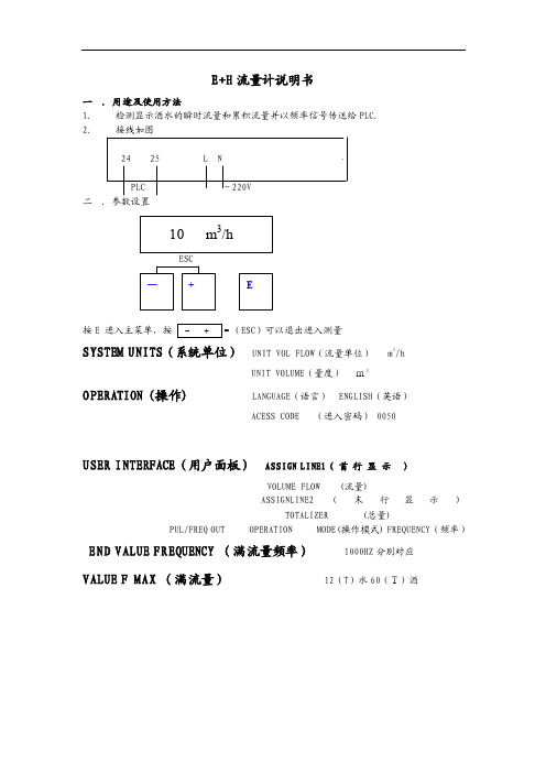
E+H 流量计说明书一 .用途及使用方法 1. 检测显示酒水的瞬时流量和累积流量并以频率信号传送给PLC. 2. 接线如图24 25 L NPLC ~220V 二 .参数设臵按E 进入主菜单,按ESC )可以退出进入测量SYSTEM UNITS (系统单位) UNIT VOL FLOW (流量单位) m 3/hUNIT VOLUME (量度) m3OPERATION (操作) LANGUAGE (语言) ENGLISH (英语)ACESS CODE (进入密码) 0050USER INTERFACE (用户面板) ASSIGN LINE1( 首 行 显 示 )VOLUME FLOW (流量)ASSIGNLINE2(末行显示)TOTALIZER (总量)PUL/FREQ OUT OPERATION MODE(操作模式) FREQUENCY (频率)END VALUE FREQUENCY (满流量频率) 1000HZ 分别对应 VALUE F MAX (满流量) 12(T )水60(T)酒二、安装1.安装位臵只有当满管时才能获得准确的测量,要避免以下安装位臵:(1)管道最高点(易聚积气泡);(2)直接向下的管线的敞开出口前;(3)泵的入口侧(防止抽压而造成的对流量管衬里的破坏);(4)有残渣聚积的场合和排水管的最低点(最好安装一个清洁阀)。
2.安装方位最适宜的方位可帮助避免气体的累积和测量管内的残渣存积。
垂直安装、流体自下而上的安装位臵为最佳方位。
若为水平安装,测量电极平面必须水平,这样可以防止由于夹带的气泡而产生的电极短时间绝缘。
空管检测功能仅当测量装臵为水平安装及变送器外壳向上时能正确工作。
3.振动如果振动剧烈,注意支撑管道和传感器;若振动非常剧烈应将传感器和变送器分开安装。
不允许利用外框承住传感器的重量,这会使外框变形并破坏内部励磁线圈。
4.出入口直管段安装传感器时要尽量避免阀门、三通、弯头等组件,与他们之间的距离应能保证所需的进口和出口直管段以确保测量精度:入口长度≥5DN,出口长度≥2DN。
HXC 超声波明渠流量计 用户使用手册说明书
HXC超声波明渠流量计用户使用手册Version 1.0海阳市海讯环保科技有限公司简易安装操作指南1、将传感器安装于标准堰槽支架上。
2、设置槽型类型及堰槽参数——按菜单键进入设置菜单,进入“管理员”->“堰槽设置”,选择或设置所使用的堰槽尺寸参数,▲/▼键切换三角堰、巴歇尔槽、矩形堰。
(原始密码000000)。
3、设置传感器参数及安装高度——按菜单键进入菜单,进入“管理员”-> “设传感器”菜单,此时用尺子测量堰槽中实际液位高度,并输入到“实测液位”后,按“确定”键保存,设备将自动计算零点高度。
4、由于实际液位并不恒定,若有可能,请临时关闭排水,待堰槽内无水流时,将“实测液位”输入为0即可。
一、产品概述1.1概述超声波明渠流量计是新型的固定式明渠标准堰槽流量测量仪器,广泛应用于各排污企业的污水流量的监测。
根据HJT 15-2019 《环境保护产品技术要求超声波明渠污水流量计》技术要求计算瞬时流量和累计流量。
广泛适用于污水处理厂、水利、水务及科研院所、排污企业的明渠标准堰槽流量的测量。
1.2存储数据(1)近十年的每日的日累计流量(2)近十年的每月的月累计流量(3)近十年的年总累流量(3)关键参数变更保存记录操作员、管理员独立密码保护,掉电不丢失,上电后自动运行。
掉电状态下数据有效保存十年。
1.3技术规格1、流量范围: 10L/s~10m3/s (由配用的量水堰槽的种类、规格确定)2、适用堰槽: 三角堰、巴歇尔槽、矩形堰3、功耗: ≤15W4、M P E: ±5%5、分辨率: 0.1mm6、测距准确度: ±3mm7、时钟误差:< 5分钟/每月8、电源: 220V市电9、信号输出: RS232、485、4-20mA10、工作环境: 温度-10℃-50℃,相对湿度0-95%二、工作原理2. 1明渠堰槽的工作原理明渠内的流量越大,液位越高;流量越小,液位越低。
如下图所示:对于一般的渠道,液位与流量没有确定的对应关系。
- 1、下载文档前请自行甄别文档内容的完整性,平台不提供额外的编辑、内容补充、找答案等附加服务。
- 2、"仅部分预览"的文档,不可在线预览部分如存在完整性等问题,可反馈申请退款(可完整预览的文档不适用该条件!)。
- 3、如文档侵犯您的权益,请联系客服反馈,我们会尽快为您处理(人工客服工作时间:9:00-18:30)。
流量计使用指南说明书
一、产品简介
流量计是一种用于测量液体或气体的流量的仪器,它广泛应用于工业、农业、石油、化工等领域。
本产品使用指南将为用户提供准确详
细的操作步骤,助您正确使用流量计,提高工作效率。
二、安装要求
1. 选择合适的位置:流量计应安装在离主管道适当距离的稳定位置,以确保测量的准确性。
2. 连接管道:将流量计与管道进行牢固连接,接口应严密,不得有
泄漏。
3. 起始调零:在使用流量计之前,应进行起始调零操作,以确保后
续测量的准确性。
三、操作步骤
1. 打开流量计电源,并确认指示灯是否亮起。
2. 进入菜单界面,依次设置测量单位、流速范围和报警参数等,根
据实际需要进行调整。
3. 进行测量操作:根据流量计的型号和功能,选择合适的测量方法,按照相应步骤进行操作。
4. 确认测量结果:流量计将显示实时测量结果,确保结果准确可靠。
5. 关闭流量计电源,结束使用。
四、常见问题解决方法
1. 测量结果异常:检查是否有漏气或漏液现象,重新校准流量计,
保持管道清洁。
2. 操作错误:仔细阅读说明书,按照操作步骤进行操作。
3. 存储异常:检查流量计的存储功能是否正常,如有问题,请联系
厂家技术支持。
五、维护保养
1. 定期清洁流量计:使用软布擦拭流量计外壳,确保表面干净整洁。
2. 避免冲击:流量计为精密仪器,应避免剧烈震动或冲击,防止损坏。
3. 定期校准:根据使用频率和要求,定期对流量计进行校准,确保
测量结果准确可靠。
六、安全注意事项
1. 使用过程中如发现异常情况或故障,应立即停止使用,并联系专
业人员进行维修或更换。
2. 避免流量计被高温、低温、潮湿或腐蚀性物质所接触,以免损坏
设备。
3. 请勿未经授权进行拆卸或维修,以免造成二次损伤。
七、售后服务
本公司提供完善的售后服务,在保修期内,对质量问题提供免费维修或更换服务。
详细的售后服务政策请参考售后服务文件。
八、结束语
本使用指南仅为流量计用户操作提供参考,并不能包含所有细节和情况。
在实际使用中,应结合具体情况进行操作。
如有疑问或需要进一步了解产品信息,欢迎联系我们的客服人员。
通过本使用指南,您将能够正确操作流量计,确保测量结果准确可靠,提高工作效率。
希望本指南能够为您的实际操作提供帮助,谢谢您的选择和支持!。