光纤光栅应变测试实验
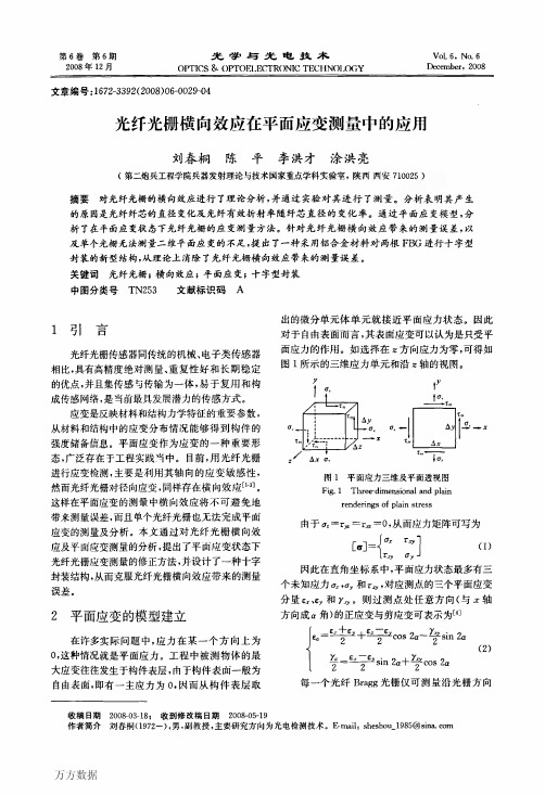
光纤光栅横向效应在平面应变测量中的应用
万方数据
光学与光电技术
第6卷
上的一个正应变,因此,如果一个自由表面的应 力状态完全未知时,就需要三个光纤Bragg光栅 构成的应变花来进行测量。而对于方向预知的 平面应变,则只需要两个光纤光栅即可实现测 量。
3 FBG的横向效应及实验测量
3.1光纤光栅的横向效应 如图2所示,在一个单向应变场中给定一个单
的作用,沿其轴向的应变记为e。,沿其横向的应变
记为‘£B,其波长的变化可表示为:
猷一A(KL£L+KBeB)
(8)
式(8)表示,Bragg波长的变化足两部分的叠加,一 部分是光栅仅受到£t作用fI寸的波长变化,另一部 分是光栅受到eB作用时的波长变化,由式(4)和式
(8)可得:
Z2n=AKL(1+塑).eL
bare grating transverse effect
由表l及图4的拟合曲线可知,随着负载的增 加,待测光纤光栅的中心反射波长向短波长方向漂 移。由实验数据所得的拟合直线斜率为一0.29 pm/tL£。由光纤光栅横向应力下的传感模型可知, 纵向拉伸的应力灵敏度约为横向应力的1.3倍‘e3; 且径向应变下光纤直径变化引起的波导效应比轴 向应变增加5倍,因而光纤Bragg光栅的横向应变 灵敏度约为0.045 pm/g.£。从而可以确定该实验 所采用光纤光栅的横向效应系数为
(9)
令口一£。/£L,对于已经安装的光纤光栅,表示
作用在光栅上的横向应变与轴向应变之比,因此它
与测点的应变场特征和光纤安装方位有关。此式
不仅适用于应变第一主应变方向与光纤轴向重合 的情况,而且表明光栅的应变灵敏系数的确定除了
取决于光栅本身的特性外,还与安装方位、被测点
应变场有关。如果使用条件满足应变第一主应变 方向与光纤轴向重合,则有EB/e-一--y,I,s为材料的
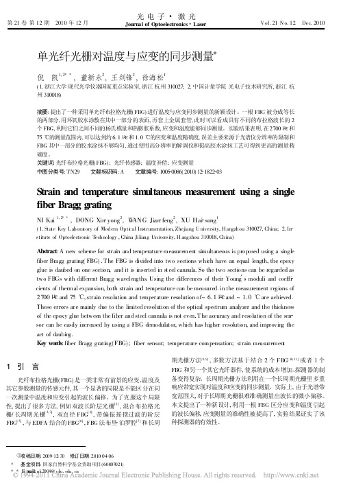
单光纤光栅对温度与应变的同步测量
and temperature measurement
图 1 传感器结构 Fig. 1 Structure of the proposed FBG sensor
3 实验结果和讨论
图 3 布拉格波长与应变的关系 Fig. 3 Relationship between Bragg wavelength and strain
4结 论
提出了一种新型的 FBG 传感器结构, 利用一根 FBG 实现 应变和温度的同步测量, 制备简单, 只需将环氧胶水涂抹于 FBG 的一部分, 并套上金属套管。通过使用高分辨率的解调仪 和保证胶水涂抹均匀, 可以达到约 6. 1 和 1. 0 ! 的应变和温 度测量精确度。
参考文献:
[ 1] Xu M G, Archambault J L, Reekie L, et al. Discrimination be tween strain and temperature effects using dual wavelength fi bre grating sensors[ J] . Electron Lett, 1994, 30 ( 13) : 1085 1 087.
fbg传感器分成等长的两部分每一部分长10mm用环氧胶水涂敷在其中一部分的表面上再套上金属套管初始的反射波长用光谱仪osa154645nm154651nm涂胶后套上金属套管的fbg减少了光纤的折射率因而这部分的布拉格波长要小于另一部分
第 21 卷 第 12 期 2010 年 12 月
光电子 激光
Journal of Optoelectronics Laser
大型装备应变检测中光纤Bragg光栅的应用研究

光纤 光栅 检 测技术 是 2 纪 9 0世 0年 代初 逐 步发 展起 来 的先进 测 试技 术 … , 所基 于 的敏 感 元 件 光 它 纤Bag 栅 ( brBaggaigF G) 近 年来 发 rg 光 i f e rg rt ,B 是 n 展迅 速 的一种 新 型光 学 无 源 器 件 , 有 不 受 光 源 功 具
维普资讯
第3 7卷 第 1 0期
20 0 7年 1 0月
激 光 与 红 外
L S R & I R A E NF ARE D
V0 . 7 . . 0 13 No 1
O tb r2 0 co e , 0 7
文章 编号 :0 1 0 8 20 )0 19 - 10 - 7 (0 7 1-0 1 4 5 0
1 引 言
发现并排除安全隐患。应变是大型装备检测最为重
要 的参 数 之一 , 反映 了工 程结 构 的 固有特征 , 局 它 对 部 特性 变化 —— 尤 其 是 对 局 部 应 力 、 部 结 构 损 伤 局 比较敏 感 J 。而 传 统 的 应 变 仪 测 量 在 使 用 中 往 往 受 到 限制 , 不能 满 足 大 型 装 备 高 精 度 、 距 离 、 布 远 分 式 检测 的技 术 要 求 。相 比较 而 言 , 纤 光 栅 检 测 技 光
i t d c d I o sd rt n o e sr i ee t n i r cie o a g c e e up n s e p t t d o e p n il n r u e . n c n ie a i ft tan d t ci n p a t flr e s a q i me t , x ai e n t r cp e o o h o c l a h i
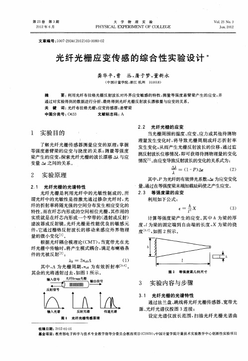
光纤光栅应变传感的综合性实验设计
z 50mi 一 8 T t
6 7 . 8 O 15 9 7 5 . 2
光纤光栅 中心波 长
1 O 1 9 1 15 9 7 2 5 . 4 1. 3 5 1O 6 .5 15 9 7 4 5. 8 1 . 6 5 1 6 2 9 . 15 9 8 5 5 . 3
第2 5卷
第 3期
大
学
物
理
实
验
Vo . 5 No 3 12 .
21 0 2年 6 月
PHYS C I AL P EX ERI MENT 0F COLLE GE
J n 2 1 u.02
文 章 编 号 :0 72 3 ( 0 20 —000 10 —94 2 1 ) 30 8 —2
光 纤光栅 应 变传 感 的综 合 性 实验 设 计 *
龚华平 , 丛 , 于梦 , 曹 屠 董新永
( 国计 量 学 院 , 江 杭 州 中 浙 301) 1 0 8
摘 关 键
要: 利用光纤布拉格光栅 反射 波长对外界应变敏感 的特性 , 测量等强度悬 臂梁产生 的应变 , 并 词: 光纤布拉格 光栅 ; 应变传感器 ; 悬臂梁
00 . 61
014 . 0 l1P3 _1
016 . 3
0 7 .1 8
029 . 2 i
由此 产 生 的应 变 误差 为 1 8 ; . £ 挠度 测 量 产生 的
4 实 验 结 果
文章 采用 光纤 光栅 对等 强度 梁产 生 的应变 进 行 测试 研 究 , 到 的实 验结果 如 下表 1 示 。 得 所
误 差 约 为 0 2mm, . 由此 导 致 的灵 敏 度 误 差 为 0 0 m/ £气流气 压 挠 动 导致 的波 长 漂 移 误 差 .2p ; ( 与前 两项 导致 的误差 可 以忽 略不计 ) 。综合 以上 因素 , 实验误 差 的影 响很小 , 本对 测量 结果没 有 基 影响。
光纤Bragg光栅温度和应变传感特性的试验研究

,
安 姜德 生 ,
40 7 ) 30 0
0 1 42 武 湖 ( . 京 工 业大 学机 械 工 程 与 应 用 电 子 技 术 学 院 , 京 10 2 ;. 汉 理 工 大 学 光 纤 传 感 技 术 中 心 , 北 武 汉 1北 北
摘要 : 在光 纤 Bag光栅传感原理的理论分析基础 上 , rg 采用保 温装置 和等 强梁结构 对其 温度 和应 变传感 特性进行 了 试验研究 , 并做 了试验 结果的误 差分析 。其 结果表 明光纤光栅 的 Bag波长随温度和 轴向应 变的变化呈现 出良好 的线性 rg
Ex e i e t lS u y 0 mp r t r n t an S n i g p rm n a t d n Te e a u e a d S r i e sn Ch r c e itc fFi e a g Gr t g a a t rsiso b rBr g a i n
20 0 8正
仪 表 技 术 与 传 感 器
I sr me t T c n q e a d S n o n tu n e h i u n e s r
20 08
No .11
第 1 1期
光 纤 B a g光 栅 温 度 和 应 变 传 感 特 性 的 试 验 研 究 rg
2 pia FbrSnigT cn lg eerhC ne , hnU ies yo eh o g , h n407 , hn ) .O t l ie es eh ooyR sac etr Wu a nvr t f cn l y Wu a 300 C ia c n i T o A s at O ebs fh erta aa s f brBagg t g( B bt c: nt ai o t t oecl n yi o f e rg r i F G)snigpi i e t prt e n t i snig r h s e h i l s i an es r c l,e ea r dsa es n np m u a rn n
光纤光栅动态应变测试实验
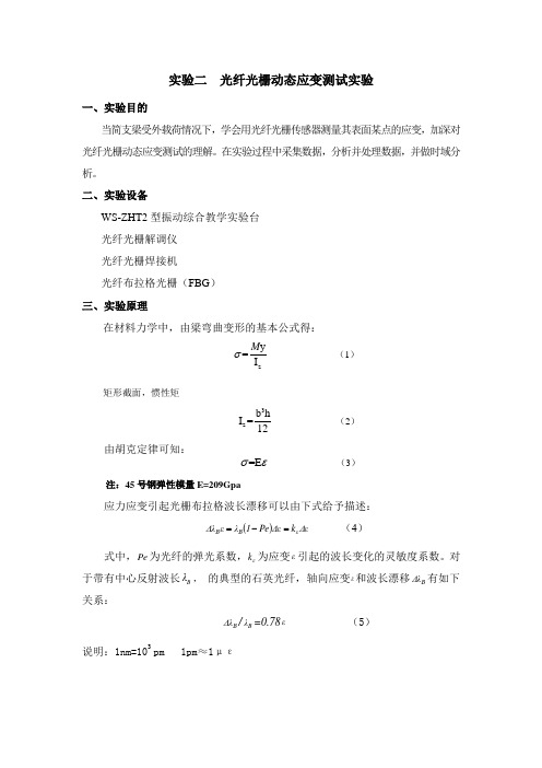
实验二 光纤光栅动态应变测试实验一、实验目的当简支梁受外载荷情况下,学会用光纤光栅传感器测量其表面某点的应变,加深对光纤光栅动态应变测试的理解。
在实验过程中采集数据,分析并处理数据,并做时域分析。
二、实验设备WS-ZHT2型振动综合教学实验台光纤光栅解调仪光纤光栅焊接机光纤布拉格光栅(FBG )三、实验原理在材料力学中,由梁弯曲变形的基本公式得:zy =I M σ (1) 矩形截面,惯性矩3z b h I =12(2) 由胡克定律可知:=E σε (3)注:45号钢弹性模量E=209Gpa应力应变引起光栅布拉格波长漂移可以由下式给予描述:()Δεk ΔεPe 1λεΔλεB B =-= (4)式中,Pe 为光纤的弹光系数,εk 为应变ε引起的波长变化的灵敏度系数。
对于带有中心反射波长B λ, 的典型的石英光纤,轴向应变ε和波长漂移B Δλ有如下关系:B Δλ/B λ=0.78ε (5)说明:1nm=103pm 1pm ≈1με四、实验内容与步骤1 测量出简支梁的长宽高以及所测点在的位置,根据公式(1)、(2)、(3),给出在激励F 作用下所测点对应的应变该变量ε,即F 与ε的关系。
2 在静载荷下采集波长,求得波长的平均值0λ3 在同一频率下分别施加F1、F2、F3,分别采集所对应的波长13λλλ、2、,求出波长变化量13λλλ∆∆∆、2、(0=-λλλ∆),然后分别代入(5)式中计算得应变13εεε、2、 3 每一实验小组分别选三个频率,分别在每个频率下施加F1、F2、F3,通过采样、计算后得到应变13εεε、2、。
4 绘出时域上的应变图,进行频谱分析,观察频谱图中频率大小是否与实验中所给频率大小相同,分析时域图中应变变化与力的变化的关系,从而判断实验与理论是否吻合。
五、实验报告要求1 从理论上推导外载荷F 与应变ε之间的关系2 先在静态下求出波长平均值0λ,通过加外载荷实验得到的波长λ,算出变化量λ∆,再转化成应变ε,用EXCEL 或MATLAB 绘制时域图,并分析图形走势3 频谱分析,试着从频谱上观察振动频率,振动幅值。
实验七、光纤光栅传感的特性测试

布拉格波长为 1550nm,1300nm 时, RB,T 分别为 0.01nm/ °C和0.0087nm/ ° C 。
与压力灵敏度表达式类似,长周期光纤光栅温度灵敏度 R L,T 可表示为
R L,T
=
dλL dT
=
⎜⎛ ⎝
nco
dΛ dT
+ Λ dnco dT
⎟⎞ ⎠
−
⎜⎜⎝⎛
nc(il
)
dΛ dT
4
盘用金属细丝相连,通过滑块另一侧的托盘内加放重物如滚珠来拉动滑块,滑块沿传光轴拉伸光纤 光栅,从而给光栅施加轴向拉力。由光谱分析仪可以看到,FBG 反射的中心波长随着轴向应力增大 而向长波偏移,将应力变化转换为波长的变化,从而达到传感的目的。(附录一中给出几种不同应 力情况下 FBG 中心波长偏移情况)。
实验数据表 1 滚珠数 2 4 6 8 10 12 14 16 18 20 22 24 26 28 30
1 λB,N 2 λB,N 3 λB,N
λB,N
ΔλB,N
δλB,N
δλB,N / λB,N
5
2.温度传感 (1)原理
由宽带光源(如 LED)发出的光信号由光环形器的 1 端口进入,由 2 端口输出进入光纤光栅, 经光纤光栅反射的光由 3 端口送入光谱分析仪。因光纤光栅的中心反射波长随温度而异,温度的升 高时,中心波长向长波方向移动,反之亦然,故可通过波长的检测推知温度的变化,实现温度传感 (附录一给出典型的光纤光栅随温度变化的反射情况)。该实验装置较应力传感实验装置多了一个 温度传感头,其结构如图 3 所示。传感头的控温仪是通过调压器改变加热丝电流大小,通过热电偶 检测温度与设定值比较控制加热丝电流通断实现恒温,从而控制传感头内的温度,传感头应具有在 一段时间间隔内阻断与外界热交换的功能,同时应尽可能地使光纤光栅周围迅速达到热平衡。因此 传感头内部是一个绝热性能较好地空腔体。将加热丝、光纤光栅和热电偶包含其内。
光纤光栅应变传感器二维应变测量方法
光纤光栅应变传感器二维应变测量方法作者:李金娟来源:《无线互联科技》2015年第02期摘要:文章介绍了光纤光栅二维应力传感测量的试验台的准备、光纤光栅的制备、光纤光栅的粘贴、实验仪器、实验过程、光纤光栅测量应变与电阻应变片的测量结果作对比。
实验结果说明利用光纤光栅应变花可以得出与电阻应变花一致的结果。
关键词:光纤光栅;电阻应变片;应变;直角应变花光纤光栅应变花进行二维平面应力测量是通过三个光纤光栅的中心波长的变化来测定应变的,电阻应变片应变花测出的应变值对光纤光栅中心波长进行标定。
所以粘贴时尽可能保证光纤光栅与对应的电阻应变片的测量方位一致。
1 实验台的准备由于本实验需要用多个光纤光栅进行二维应力测量,所以不能使用一般的等强度梁,而是用一个十字架形结构,实际上也是一种等强度梁,不过这种装置有两个等强度梁,分别作为十字架的X轴向和Y轴向,用来施加压力,如图1所示。
这是实验的被测表面的俯视图,表面是由我们用一块马口铁皮做成的。
实验时在X轴、Y 轴方向分别悬挂砝码盘。
砝码的重力通过试验台的等悬梁臂结构拉伸X或者Y方向的铁皮,铁皮的应力的变化引起光纤光栅中心波长的变化,因此为了保证试验的效果,光纤光栅的粘贴必须使光栅光纤紧贴被测表面时同时发生应变。
2 光纤光栅的制备实验台准备好后重要的是制备光纤光栅,本实验使用3只不同中心波长的光纤光栅,串联成直角应变花来测试动态应力的变化,因而需制备3只不同波长的光纤光栅。
由于实验条件的限制,试验室中只有两块相位掩模板,在实验室中只能制备两只光纤光栅,另外一只光纤光栅是已经制备好的光纤光栅。
三只光纤光栅的波长位置分别在:1532nm,1544nm,1548nm处附近。
根据实验条件,组建一个光纤光栅制作系统,制作方法采用目前最有效,也是最流行的相位掩模法,其实验系统如图2所示。
本实验用光纤,是载氢掺锗光敏光纤-普通光纤经过载氢处理(在室温下,压强为107Pa 的容器中,载氢两周左右),使得普通通信光纤的光敏性大大增加,达到写制光栅的要求。
- 1、下载文档前请自行甄别文档内容的完整性,平台不提供额外的编辑、内容补充、找答案等附加服务。
- 2、"仅部分预览"的文档,不可在线预览部分如存在完整性等问题,可反馈申请退款(可完整预览的文档不适用该条件!)。
- 3、如文档侵犯您的权益,请联系客服反馈,我们会尽快为您处理(人工客服工作时间:9:00-18:30)。
†
* Author to whom correspondence should be addressed; E-Mail: ofrazao@inescporto.pt; Tel.: +351-226082328; Fax: +351-22608799. Received: 28 December 2013; in revised form: 28 March 2014 / Accepted: 8 April 2014 / Published: 14 April 2014
Abstract: An ultra-high sensitive strain sensor is proposed. The sensing head, based on the post-processing of a fiber Bragg grating, is used to perform passive and active strain measurements. Both wavelength and full width half maximum dependences with the applied strain are studied for the passive sensor, where maximum sensitivities of 104.1 pm/µε and 61.6 pm/µε are respectively obtained. When combining the high performance of this sensor with a ring laser cavity configuration, the Bragg grating will act as a filter and high resolution measurements can be performed. With the proposed sensor, a resolution of 700 nε is achieved. Keywords: strain sensor; post-processing; fiber Bragg grating
Fibers 2014, 2, 142-149; doi:10.3390/fib2020142
OPEN ACCESS
fibers
ISSN 2079-6439 /journal/fibers Article
Ultra-High Sensitive Strain Sensor Based on Post-Processed Optical Fiber Bragg Grating
Marta S. Ferreira 1,2, Jörg Bierlich 3,†, Martin Becker 3,†, Kay Schuster 3,†, José L. Santos 1,2 and Orlando Frazão 1,2,*
1
2
3
INESC Porto, Rua do Campo Alegre, 687, Porto 4169-007, Portugal; E-Mails: msaf@inescporto.pt (M.S.F.); josantos@fc.up.pt (J.L.S.) Faculdade de Ciências da Universidade do Porto, Rua do Campo Alegre, 687, Porto 4169-007, Portugal; E-Mail: josantos@fc.up.pt IPHT Jena, Institute of Photonic Technology, Albert-Einstein-Str. 9, Jena 07745, Germany; E-Mails: joerg.bierlich@ipht-jena.de (J.B.); martin.becker@ipht-jena.de (M.B.); kay.schuster@ipht-jena.de (K.S.) These authors contributed equally to this work.
Fibers 2014, 2 1. Introduction
143
Optical fiber tapers, usually applied in sensors or fiber lasers, can be divided in two groups according to their manufacture: mechanical or chemical tapers. Mechanical tapers, produced by stretching the fiber, present reduced core and cladding diameters. Usually, these structures have a biconical structure. Different fibers have been tapered such as a large-mode-area microstructured fiber [1], suspended-core fiber [2] and large-mode-area holey fiber [3]. The development of these, and other structures, has opened a new window in optical fiber sensing. For instance, the tapering of long period gratings (LPGs) proved to be suitable to measure pressure [4], temperature and strain [5]. In addition, the use of fiber Bragg gratings (FBGs) in tapered fibers was used to measure strain and temperature [6]. A different approach has been proposed by depositing metals in tapered fibers, in order to have surface plasmon resonances [7,8]. The production of an S-tapered fiber sensor led to an axial strain sensor with a maximum sensitivity of −183.4 pm/µε . Chemically etched tapers do not suffer modification of the fiber core, whereas the cladding is partially or totally removed. Besides the biconical tapers [10,11], fiber tip sensors have been proposed. These sensors present high-sensitivity to the environment [12] and are very well suited to perform biosensing [13]. Fiber Bragg gratings have attracted significant attention not only from academia, but also from industry [14]. These structures have been widely explored as sensors as well as optical filters that are suitable, for instance, for application in fiber lasers. The periodical structure is easy to manufacture, reproducible and very straightforward for application in various situations. In this paper, a sensor based on a post-processed fiber Bragg grating is proposed. The sensing head is subjected to strain measurements, where it exhibits an ultra-high sensitivity. Two different configurations are compared, for passive and active measurements. 2. Experimental Results A 3 mm long fiber Bragg grating (FBG) was written in photosensitive single mode fiber (SMF) using an excimer laser. Due to the photosensitivity of the fiber, there was no need to hydrogenate it prior to the grating inscription.was produced by splicing the FBG to the end section of SMF. The end section of the sensor was cleaved, guaranteeing that there were 2 mm of SMF with no inscription between the FBG and the fiber end. This ensured that the post-processing would not destroy the FBG length. The fiber tip with the FBG was then subjected to wet chemical etching, being submerged in a 40% hydrofluoric acid (HF) solution during 55 min. This led to a tapering of the fiber, with a final tip diameter of ~12 µm, and a length of 4.5 mm, accordingly to the scheme of Figure 1a. Due to the strength of the etch near the end face of the fiber tip relative to that throughout the cladding, the sensor acquired a conical shape. Consequently, the reflection spectrum of the grating changed, not only did its Bragg wavelength shift ~10 nm, but also the full width half maximum (FWHM) increased from 0.36 nm to 6.03 nm, see Figure 1b. This chirp behavior had a strong influence in the sensing head response to strain. Due to the predictability of the etching behavior, it was possible to obtain several sensing heads with identical properties.