蜗杆斜齿轮设计软件
蜗杆蜗轮设计软件
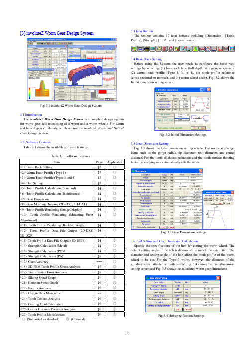
[3] involute Σ Worm Gear Design SystemFig. 3.1 involute Σ Worm Gear Design System3.1 IntroductionThe involute Σ Worm Gear Design System is a complete design system for worm gear sets (consisting of a worm and a worm wheel). For worm and helical gear combinations, please use the involute Σ Worm and Helical Gear Design System .3.2. Software FeaturesTable 3.1 shows the available software features.Table 3.1. Software FeaturesItem Page Applicable<1> Basic Rack Setting13 ○<2> Worm Tooth Profile (Type 1) 13 ○<3> Worm Tooth Profile (Types 3 and 4) 13 ◎ <4> Hob Setting13 ○ <5> Tooth Profile Calculation (Standard) 14 ○ <6> Tooth Profile Calculation (Interference)14 ◎ <7> Gear Dimension14 ○ <8> Gear Meshing Drawing (2D-DXF, 3D-DXF) 14 ○<9> Tooth Profile Rendering (Image Display) 14◎ <10> Tooth Profile Rendering (Mounting Error Adjustment)14◎<11> Tooth Profile Rendering (Backlash Angle) 14◎ <12> Tooth Profile Data File Output (2D-DXF, 3D-DXF)14○<13> Tooth Profile Data File Output (3D-IGES) 14 ◎ <14> Strength Calculation (Metal) 14 ○ <15> Strength Calculation (POM) 14 ○ <16> Strength Calculation (PA) 15 ◎ <17> Gear Accuracy--- ○ <18> 2D-FEM Tooth Profile Stress Analysis 15 ◎ <19> Transmission Error Analysis 15 ◎ <20> Sliding Speed Graph 15 ◎ <21> Hertzian Stress Graph 16 ◎ <22> Fourier Analysis 16 ◎ <23> Design Data Management -- ○ <24> Tooth Contact Analysis 16 ◎ <25> Bearing Load Calculation 16 ○ <26> Center Distance Variation Analysis 16 ◎ <27> Tooth Profile Modification 16◎○ (Supported as standard) ◎ (Optional)3.3 Icon ButtonsThe toolbar contains 17 icon buttons including [Dimension], [Tooth Profile], [Strength], [FEM], and [Transmission].3.4 Basic Rack SettingBefore using the System, the user needs to configure the basic rack settings by selecting: (1) basic rack type (full depth, stub gear, or special), (2) worm tooth profile (Type 1, 3, or 4), (3) tooth profile reference (cross-sectional or normal), and (4) worm wheel shape. Fig. 3.2 shows the Initial dimension setting screen.Fig. 3.2 Initial Dimension Settings3.5 Gear Dimension SettingFig. 3.3 shows the Gear dimension setting screen. The user may change items such as the gorge radius, tip diameter, root diameter, and center distance. For the tooth thickness reduction and the tooth surface thinning factor , specifying one automatically sets the other.Fig. 3.3 Gear Dimension Settings3.6 Tool Setting and Gear Dimension CalculationSpecify the specifications of the hob for cutting the worm wheel. The default setting angle of the hob is determined to match the axial pitch. The diameter and setting angle of the hob affect the tooth profile of the worm wheel to be cut. For the Type 3 worm, however, the diameter of the grinding wheel affects the tooth profile. Fig. 3.4 shows the Tool dimension setting screen and Fig. 3.5 shows the calculated worm gear dimensions.Fig.3.4 Hob specification SettingsFig. 3.5 Calculated Worm Gear Dimensions3.7 Tooth Profile Calculation(1) Standard Tooth Profile AnalysisThe System calculates the tooth profile of the worm wheel using the hob specifications specified in Fig. 3.4. (2) Interference AnalysisSetting a large lead angle prevents the worm from contacting the worm wheel at the center of the tooth flank because of the lead difference between the worm and the hob. The Interference Analysis feature analyzes the tooth profile of the hob to help the user eliminate interference. For details, refer to Section 3.20.Fig. 3.6 Tooth Profile Calculation3.8 Gear Meshing DrawingFig. 3.7 shows the cross-sectional tooth profiles of the worm and the wheel meshed at the axial center of the worm. Even if the teeth seem to be meshed correctly in this 2D drawing, interference may occur in other sections. Incorrect tooth contact due to interference or assembly errors can be checked using the Tooth Profile Rendering feature in Section 3.9.Fig. 3.7 Gear Meshing Drawing3.9 Tooth Profile RenderingUsing the Tooth Profile Rendering feature may reveal severe interference on some tooth flanks of the wheel as shown in Fig. 3.8 and Fig. 3.9, even if it seems that there is no interference in this 2D drawing in Fig. 3.7. Fig. 3.10 shows the control form used for Tooth Profile Rendering. The user can not only change the viewing angle by specifying the X-, Y-, and Z-axis rotation angles, but also scale the image by entering the Z-axis travel distance. It is also possible to observe how the meshing state changes by varying the angle and position of the worm shaft.The control form also offers optional features: The first feature provides (1) worm shaft angle, (2) worm shaft position, and (3) center distanceadjustments. The second feature is used to display the backlash angle.Fig. 3.8 Tooth Profile Rendering (Left) Fig. 3.9 Tooth Profile Rendering (Right)Fig 3.10 Tooth Profile Rendering Control Form3.10 Tooth Profile Data File OutputAs shown in Fig. 3.11, the user can choose to output worm and wheel tooth profile data into four kinds of CAD-format files. Fig. 3.12 is an example of a 3D worm wheel tooth profile displayed in a CAD system.File 3.11 Tooth Profile File Fig. 3.12 3D Tooth Profile Data in a CAD System (IGES)3.11 Initial Strength Calculation SettingFig. 3.13 shows the Initial strength calculation settings screen, in which the user can select the material used for the worm wheel. Clicking the [Select material] button displays the Metal material selection screen asshown in Fig. 3.14.Fig. 3.13 Initial Strength Calculation Settings (with [Select Material] button)Fig. 3.14 Metal Material Selection3.12 Strength CalculationFig. 3.15 shows the strength setting screen for resin (PA) materials. The results of the strength calculation for the resin and metal materials are shown in Fig. 3.16 and Fig. 3.17, respectively.Fig. 3.16 Strength Calculation Result for Resin Material (PA)Fig. 3.17 Strength Calculation Result for Metal Material3.13 FEM Tooth Profile Stress AnalysisStress analysis can be easily performed by simply clicking the [FEM] button after strength calculation. Fig. 3.18 shows the FEM analysis setting screen. The user may change the Young modulus, Poisson ratio, number of partitions, and load values. Fig. 3.19 and Fig. 3.20 show the results of FEM analysis on the worm and the wheel, respectively.Fig. 3.18 FEM Analysis SettingsFig. 3.15 Strength Specification Settings for Resin Material (PA)Fig. 3.19 FEM Analysis on Worm Fig. 3.20 FEM Analysis on Wheel (Stress=ó1) (Stress=ó1)3.14 Transmission Error AnalysisFig. 3.21 and Fig. 3.22 show the setting screens for transmission error analysis. The graphs in Fig. 3.23 and Fig. 3.24 show the results of analysis on the rotation transmission error and wow and flatter, respectively. These errors were raised by assembling the worm and wheel pair to have pitch and radial runout errors and rotating the worm by one turn. The graphs in Fig. 3.25 and Fig. 3.26 also show the results of analysis on the rotation transmission error and wow and flatter, respectively, but they were raised by rotating the wheel by one turn.Fig. 3.21 Transmission Error Analysis Fig. 3.22 Transmission Error Settings (Worm) Analysis Settings (Wheel)Fig. 3.23 Rotation Transmission Fig. 3.24 Wow & Flatter 1 Error 1Fig. 3.25 Rotation Transmission Fig. 3.26 Wow & Flatter 2 Error 23.15 Frequency AnalysisFig. 3.27 shows the result of analysis on the frequency measured when the worm is rotated by one turn; Fig. 3.28 shows the result of analysis on the frequency measured when the wheel is rotated by one turn.Fig. 3.27 Fourier Analysis 1 Fig. 3.28 Fourier Analysis 23.16 Hertzian Stress and Sliding Speed GraphsFig. 3.29 shows the Hertzian stress exerted on the tooth flank surface when the worm is rotated by one turn; the graph in Fig. 3.30 shows the sliding speed measured during that time.These graphs are useful after the transmission error analysis.Fig. 3.29 Hertzian Stress Graph Fig. 3.30 Sliding Speed Graph3.17 Center Distance VariationThis feature simulates how the center distance changes when, like on a double-flank gear rolling tester, the worm and the wheel rotate while mutually pressing each other's tooth flanks. The results of this simulation are shown in Fig. 3.31 (circle graph) and Fig. 3.32 (line graph), respectively.Fig. 3.31 Center Distance Variation Fig. 3.32 Center Distance Variation Graph 1 Graph 23.18 Bearing Load CalculationFig. 3.33 shows the bearing load setting screen; Fig. 3.34 shows the result of the bearing load calculation.Fig. 3.33 Bearing Load Calculation Fig. 3.34 Bearing Load Settings Calculation Result3.19 Tooth Contact AnalysisAn example of analysis on the tooth flanks of the worm and worm wheel is shown below. The setting screen in Fig. 3.35 provides various settings for tooth contact analysis. In this example, analysis will be made on the tooth contact of the worm and wheel specified in Fig. 3.3. Here, the number of rotation position partitions is set to "4" although it accepts values in a range of 3 to 20. Fig. 3.36 shows a tooth contact state between the worm and the wheel and Figs. 3.37 to 3.40 show their tooth contact states by 1/4 pitch. This example, however, does not take the deflection of the teeth and the pitch error into account.It is noticeable that tooth contact pattern in Fig. 3.36 slightly differs from the tooth profile rendering image shown in Fig. 3.8. The reason for this is that the analysis in this example was made at a fineness that is two times (up to five times allowed) greater than that of the number of tooth profilepartitions setting used for the tooth profile rendering image of the wheel.Fig. 3.35 Tooth Contact Analysis SettingsFig. 3.36 Tooth Contact State (Worm and Wheel)Fig. 3.37 Tooth Contact State 1 Fig. 3.38 Tooth Contact State 2Fig. 3.39 Tooth Contact State 3 Fig. 3.40 Tooth Contact State 4In addition to viewing the tooth contact state as a color pattern as shown in Fig. 3.36, to examine it in more detail, the user may click the [Tooth contact value] button in Fig. 3.35 to display the contact clearance values in Fig. 3.41. The slider control bar at the bottom of the screen can be used to change the target rotation position (1 to 4 in this example).Fig. 3.41 Contact Clearance Values3.20 Example of Hob Tooth Profile Analysis Simulation 1)3.20.1 IntroductionThe tooth contact state between the worm and the worm wheel in mesh will be influenced by the hob used to cut them. The contact point will be deviated to a great extent particularly if the lead angle of the worm is large or if there is a significant difference between the diameters of the worm and the hob. Since this is caused by the lead difference between the worm and the hob, to obtain a proper tooth contact, it is necessary to modify the tooth profile of the hob. The following is the result of examination on the tooth contact and backlash of the worm gear using the involute Σ Worm Gear Design System .3.20.2 Examined Gear SetThe specifications of the examined gear set are shown in Table 3.2. Compared with the worm's pitch diameter of 12 mm, the pitch diameter of the hob used to cut the worm wheel (shown in Fig. 3.42) is 36 mm. This requires the hob to be installed at a setting angle of 14.5916 (degrees) to match the axial pitch.Fig. 3.42 Hob DimensionsTable 3.2 Worm Gear Specifications3.20.3 Tooth Profile RenderingFig. 3.43 and Fig. 3.44 show the tooth profile rendering images of the Type 1 worm and worm wheel. It can be seen that, while there are three occurrences of major interference on the worm and wheel cut using the non-modified hob, the modified hob has no interference and the worm and wheel mesh without interference around the center of the tooth flank.Fig. 3.43 Tooth Profile Rendering Fig. 3.44 Tooth Profile Rendering (Non-Modified Hob) (Modified Hob)3.20.4 Relationship between Hob Diameter and BacklashFig. 3.45 shows the change in the backlash amount when the diameter of the non-modified hob is increased from 12 to 100 mm. The graph shows that the backlash becomes the maximum at a hob diameter of 18 mm and decreases as the hob diameter increases. With the modified hob (shown in Fig. 3.47), the amount of change in backlash improves significantly and the backlash becomes approximately constant as shown in Fig. 3.26.Fig. 3.45 Hob Diameter versus Fig. 3.46 Hob Diameter versus Backlash Graph 1 Backlash Graph 2Fig. 3.47 Tooth Profile of Modified Hob1) MPT2001-Fukuoka, Excerpt from Amtec Catalog, 2001。
ProE中斜齿轮的创建与运动仿真

Pro/E中斜齿轮的创建与运动仿真一、斜齿轮的建模分析建模分析(如图1-1所示):(1)输入参数、关系式,创建齿轮基本圆(2)创建渐开线(3)创建扫引轨迹(4)创建扫描混合截面(5)创建第一个轮齿(6)阵列轮齿图1-1渐开线斜齿圆柱齿轮建模分析二、斜齿轮的建模过程1.输入基本参数和关系式(1)单击,选择“零件”,在新建对话框中输入文件名“hecial_gear”,然后单击;(2)在主菜单上单击“工具”→“参数”,系统弹出“参数”对话框,如图2-1所示;图2-1参数”对话框(3)在“参数”对话框内单击按钮,可以看到“参数”对话框增加了一行,依次输入新参数的名称、值、和说明等。
需要输入的参数如表3-2所示;名称值说明名称值说明Mn6法面模数HA___齿顶高Z34齿数HF___齿根高ALPHA20压力角X0变位系数BETA16螺旋角D___分度圆直B50齿轮宽度DB___基圆直径HAX 1.0齿顶高系数DA___齿顶圆直径CX0.25顶系系数DF___齿根圆直径注意:表2-1中未填的参数值,表示是由系统通过关系式将自动生成的尺寸,用户无需指定。
完成后的参数对话框如图2-2所示:图2-2“参数”对话框(4)在主菜单上依次单击“工具”→“关系”,系统弹出“关系”对话框,如图2-3所示;(5)在“关系”对话框内输入齿轮的分度圆直径关系、基圆直径关系、齿根圆直径关系和齿顶圆直径关系。
由这些关系式,系统便会自动生成表3-2所示的未指定参数的值。
输入的关系式如下:/*齿轮基本关系式(可不用输入,只做解释用)ha=(hax+x)*mnhf=(hax+cx-x)*mnd=mn*z/cos(beta)da=d+2*hadb=d*cos(alpha)df=d-2*hf完成后的“关系”对话框如图2-3所示;图2-3 “关系”对话框2.创建齿轮基本圆(1)在工具栏内单击按钮,系统弹出“草绘”对话框;(2)选择“FRONT”面作为草绘平面,选取“RIGHT”面作为参考平面,参考方向为向“右”,如图2-4所示。
械设计课程设计的好助手——减速箱、减速器计算软件
械设计课程设计的好助手——减速箱、减速器计算软件
Gearbox是基于Windows开发的适用于圆柱齿轮减速器、圆锥齿轮减速器和蜗杆蜗轮减速器设计以及齿轮传动机构设计的辅助设计系统。
该系统包括速比分配、几何参数计算、强度计算、精度查询、结构简图、数据输出和参数化零件图和装配图设计等子功能模块。
本系统具有操作简单、自动化程度高、灵活性等特点,对机械行业生产厂家,尤其是减速器生产厂家来说,是一个非常实用、高效的设计软件。
最新3.0版下载地址:/download/gearbox.zip。
国内外优秀齿轮设计开发软件介绍
无图版| 风格切换| 帮助| Home首页| 论坛首页»您尚未登录注册| 搜索| 新搜索| 社区服务社区服务银行勋章中心FTP服务中心风格切换wind中国机械CAD论坛»齿轮类零件及减(增)速机设计、制造及应用专区»【重点推荐】国内外优秀齿轮设计开发软件介绍本页主题: 【重点推荐】国内外优秀齿轮设计开发软件介绍打印| 加为IE收藏| 复制链接| 收藏主题| 上一主题| 下一主题mrmrw志于齿道精于齿艺小中大引用推荐编辑只看复制【重点推荐】国内外优秀齿轮设计开发软件介绍齿轮设计是一个计算工作量很大的工作,反复的计算是齿轮设计不可避免的过程,还有就是由于齿轮计算过程中涉及一些超越方程,若是采用手工计算,其难度和工作量非常大。
另外,齿轮的数学模型已经基本成熟,采用专业开发的软件作为齿轮开发工具是一个很不错的选择。
级别: 论坛版主精华: 1发帖: 854威望: 5 点金钱: 870 机械币贡献值: 0 点注册时间:2006-11-04 最后登录:2010-06-03 本帖将搜集国内外优秀的齿轮设计软件工具介绍资料,向大家介绍。
注意:本帖主要是介绍,不提供下载D版软件。
跟帖者可推荐自己使用或者知道的专业齿轮软件的信息,便于大家学习与参考!志于齿道精于齿艺顶端Posted: 2008-07-07 08:03 | [楼主]mrmrw志于齿道精于齿艺小中大引用推荐编辑只看复制图片:级别: 论坛版主精华: 1发帖: 854威望: 5 点金钱: 870机械币贡献值: 0点注册时间:2006-11-04最后登录:2010-06-03图片:图片:图片:图片:图片:图片:图片:图片:图片:图片:图片:图片:图片:图片:第一款软件:渐开线齿轮专家系统齿轮设计专家系统 6.00版涉及内容:1.详细计算2.齿轮精度3.强度校核4.几何计算软件简介:渐开线圆柱齿轮设计专家系统是集国内外齿轮最新研究成果和实践经验,结合最新国家及国际标准,经知名齿轮专家的几十年研究和提炼,推出的全新设计的齿轮专家系统。
GearTrax 注册及使用指南 for SW
GearTrax注册及使用指南
Camnetics系列汉化插件
网盘下载地址:/s/1c0mqv2S
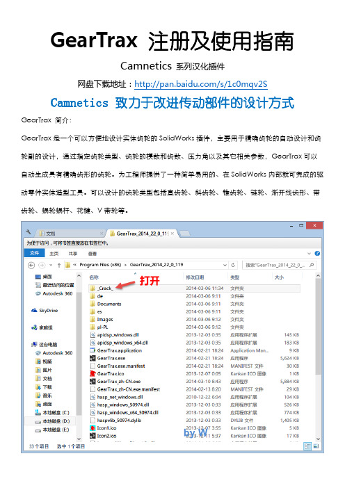
Camnetics 致力于改进传动部件的设计方式GearTrax 简介:
GearTrax是一个可以方便地设计实体齿轮的SolidWorks插件,主要用于精确齿轮的自动设计和齿轮副的设计,通过指定齿轮类型、齿轮的模数和齿数、压力角以及其它相关参数,GearTrax可以自动生成具有精确齿形的齿轮。
为工程师提供了一种简单易用的、在SolidWorks内部就可完成的驱动零件实体造型工具。
可以设计的齿轮类型包括直齿轮、斜齿轮、锥齿轮、链轮、渐开线齿形、带齿轮、蜗轮蜗杆、花键、V带轮等。
Camnetics 致力于改进传动部件的设计方式。
-----------------------【汉化问题反馈】--------------------------
邮箱:hua200905@
/991421914(QQ空间)
********
QQ群:
GearTeq汉化群(182945790)
SolidWorks 技术交流(133712153)
SolidWorks 机械3D化(133713690)
CamTrax64汉化群(182945602)
整理及制作by W。
蜗轮蜗杆KISSsoft分析
蜗轮蜗杆KISSsoft分析摘要:本文主要包含KISSsoft软件简介,KISSsoft软件在蜗轮蜗杆分析操应用的作步骤及注意事项,如何分析评价传动误差的影响。
一、KISSsoft软件简介KISSsoft是冲变速箱公司内部使用的一个软件发展而来,包含了各种齿轮、紧固件、轴承、轴等模块。
具有计算结果准确、操作过程简便的特点,适用于在机械行业常规零件的计算分析,尤其擅长对齿轮进行分析。
齿轮是机械传动的主要使用方式,在机械传动领域应用非常广泛,但齿轮设计是一个计算工作量很大的工作,在设计过程中需要反复计算,若采用手工计算,其难度和工作量非常大。
KISSsoft工程软件可用于:齿轮设计、优化和评级;螺旋齿轮加工仿真;锥齿轮、准双曲面齿轮、蜗杆齿轮和交叉轴斜齿轮、平面齿轮的评级;轴承非线性刚度分析、轴承应力计算,修改参考寿命等级;轴变形和强度分析;联轴器连接,高强度螺栓计算。
长度角度传感器是测量机械臂伸缩长度和角度的传感器,其中经常用到齿轮或蜗轮蜗杆进行传动,而齿轮的传动误差直接影响传感器的测量精度,本文主要针对蜗轮蜗杆的传动对长度角度传感器的影响进行仿真分析。
二、齿轮分析过程1、材料选择与编辑KISSsoft自带材料库,并且材料的种类比较多,软件中的材料库是根据计算单元进行分类。
比如轴计算使用轴材料库、齿轮计算使用齿轮材料库。
如果初始材料库中没有想要的材料,如图1所示。
也可以自定义材料,利用快速模块输入或建立材料到材料库。
图1如材料库中无对应的材料,可手动添加材料:点击工具栏添加按钮;选择“材料,基本数据”,点击编辑;点击添加行;输入材料参数,保存;点击“材料,包络环面齿轮”,选择编辑;选择添加行,选择上面添加的材料名称,设置参数,点击保存,如图2所示;如果提示有误,可点击右侧“+”,选择自行输入,点击确定,如图3所示。
图32、齿轮基本参数设定:本此分析蜗轮蜗杆采用渐开线齿形,它的特点是齿形容易加工,齿根粗壮、轻度高,齿面由同一条曲线构成,当中心距存在一定误差时也能正确啮合。
KISSsoft Hirnware v10.2004齿轮方面软件

Altair.HyperWorks.Solvers.v12.0.224.HotFix.Win32_64.&.Linux64 3CD
Altair SimLab Composer 2015 v5.0.2.0 Win32_64 2CD 3D场景创建软件
SIMLAB Composer是一个3D框架,提供了工作台的建设场景,渲染,共享,动画和自动化,SIMLABComposer的目的是使艺术工
等,目前实验室利用 CFDRC 并配合实验系统以了解燃料电池的作用机制)
CFDRC v2009.0 Win64 1CD
CFDRC.v2004 User Manual-ISO 1CD
AutoSEA2 2004.v2.5.0.8-ISO 1CD(噪声和振动分析软件,它代表了统计能量分析(SEA)领域的最高水平)
Altair.Acusolve.v12.0.311.HotFix.Win32_64.&.Linux64 3CD计算流体动力学(CFD)求解器
Altair AcuSolve是一款领先的基于有限元的通用计算流体动力学(CFD)求解器,可以解决非常复杂的工业和科研问题。AcuSolve的稳健性和扩展性求解技术在全非结构网格基础上仍能保持无与伦比的求解精度。无论是稳态的RANS仿真应用还是复杂瞬态的多物理场仿真,AcuSolve都能容易求解并保证良好的精度。
领先的技术 精确的结果
AcuSolve是一款基于Galerkin/Least-Squares (GLS)有限元方法的求解器,GLS是一种高阶精确并且稳健的算法,可用于包括压力在内所有变量的等阶节点插值。这一算法专门为在各种工况及网格类型下保持相关参数整体和局部守恒开发的。除了优秀的空间精确性,AcuSolve还具有二阶时间积分功能,因此它能在每个时间步实现快速非线性收敛,进而获得时间精度。
基于SolidWorks的斜齿轮参数化三维建模

基于SolidWorks的斜齿轮参数化三维建模SolidWorks是一款广泛应用于机械设计领域的三维建模软件。
在机械设计中,斜齿轮常常被用于传递动力和转矩。
在SolidWorks中,我们可以很容易地进行斜齿轮的参数化三维建模。
首先,我们需要定义斜齿轮的各个参数。
斜齿轮有许多参数,其中包括压力角、齿数、分度圆直径、齿宽等。
压力角是指齿面与法平面间的夹角,齿数是指齿轮上的齿数,分度圆直径是指齿轮的中心直径。
由于斜齿轮具有不同的参数,所以要根据要求来定义这些参数。
接下来,我们可以开始建模。
首先,我们需要绘制分度圆。
在SolidWorks的草图模式下,使用圆工具绘制一个示意圆圈,并确定其大小和位置。
然后,使用切削工具切去多余的部分。
接下来,绘制出齿身和齿顶。
在草图模式下,使用线性工具绘制出齿身和齿顶,并进行修剪以得到完整的齿面形状。
然后,绘制出齿槽。
在草图模式下,使用线性工具绘制出齿槽形状,并进行修整以使其与齿身和齿顶一致。
最后,我们需要在三维模式下提取出斜齿轮的主体,进行渲染和实体化。
点击拉伸命令,然后指定草图中的线段作为拉伸路径,即可将草图拉伸为一个3D斜齿轮。
最后,可以添加材质和纹理等效果,使其更加逼真。
需要注意的是,斜齿轮的制造过程更加复杂,必须对其进行加工、热处理和质量检测等环节,确保其精度和质量。
通过SolidWorks可以模拟斜齿轮的三维模型,为之后的加工和质量检测提供方便,并且能够看到斜齿轮的动态参数,以及对各种参数的敏感度,为优化设计提供帮助。
总之,SolidWorks提供了广泛的工具和功能,让工程师能够更加方便地进行斜齿轮的参数化三维建模设计,这种建模方式可以在实际斜齿轮制造过程中提供帮助和指导。
在斜齿轮参数化三维建模中,涉及到许多的数据,例如压力角、齿数、分度圆直径、齿宽等。
这些数据的不同取值会对斜齿轮的机械性能产生影响,下面对这些数据进行分析。
1. 压力角压力角是斜齿轮齿面上的轴向力作用于法向方向的角度。
- 1、下载文档前请自行甄别文档内容的完整性,平台不提供额外的编辑、内容补充、找答案等附加服务。
- 2、"仅部分预览"的文档,不可在线预览部分如存在完整性等问题,可反馈申请退款(可完整预览的文档不适用该条件!)。
- 3、如文档侵犯您的权益,请联系客服反馈,我们会尽快为您处理(人工客服工作时间:9:00-18:30)。
[4] involute Σ Worm and Helical Gear Design SystemFig. 4.1 involute Σ Worm and Helical Gear Design System4.1 IntroductionThe involute Σ Worm and Helical Gear Design System is a complete design system for worm and helical gear sets. 4.2. Software FeaturesTable 4.1 shows the available software features.Table 4.1. Software FeaturesItem Page Applicable <1> Basic Rack Setting 18 ○ <2> Worm Tooth Profile (Type 1) 18 ○ <3> Worm Tooth Profile (Type 3,4) 18 ◎<4> Gear Dimension 18 ○<5> Gear Meshing Drawing18 ○ <6> Tooth Profile Rendering (Image Display) 19 ◎ <7> Tooth Profile Rendering (Mounting Error Adjustment)19◎<8> Helical Gear Specification Correction 19 ◎ <9> Tooth Profile Data File Output (2D-DXF, 3D-DXF)20○<10> Tooth Profile Data File Output (3D-IGES) 20 ◎<11> Strength Calculation (POM)18 ○ <12> 2D-FEM Tooth Profile Stress Analysis 19 ◎<13> Transmission Error Analysis 19 ◎<14> Fourier Analysis20 ◎ <15> Sliding Speed and Hertzian Stress Graphs 20 ◎ <16> Design Data Management -- ○ <17> Tooth Profile Modification 18 ◎ <18> Strength Calculation (Polyamide) 18 ◎ <19> Tooth Contact Analysis20◎○ (Supported as standard) ◎ (Optional)4.3 Basic Rack SettingFig. 4.2 shows the Basic rack initial dimension setting screen. For the worm type, Type 1, 3, or 4 can be selected.Fig.4.2 Basic Rack Initial DimensionSetting4.4 Gear Dimension SettingThe user can specify the module, number of starts, number of teeth, pressure angle, and reference tip diameter to calculate the gear dimensions. The center distance and tooth surface thinning factor can be specified as desired. Fig. 4.3 shows the gear dimension setting screen and Fig. 4.4 shows the calculated gear dimensions. The Tooth profile modification screen shown in Fig. 4.4 enables the user to modify the tooth profile of the worm.Fig. 4.3 Gear Dimension SettingsFig. 4.4 Tooth Profile ModificationFig. 4.5 Calculated Worm Gear Dimensions4.5 Tooth Profile DrawingFig. 4.6 shows the cross-sectional tooth profiles of the worm and the helical gear meshed at the axial center of the worm.Fig. 4.6 Gear Meshing Drawing4.6 Strength CalculationFig. 4.7 shows the strength setting screen. For helical gears (resin), the System calculates the strength based on the Lewis formula. The stress values are experimental values taking into account the temperature and life cycle of the material. Fig. 4.8 shows the result of the strength calculation. The available material options for helical gears are M90-44, KT-20, GH-25, and Nylon.Fig. 4.7 Initial Strength Calculation SettingsFig. 4.8 Strength Calculation Result4.7 Tooth Profile RenderingFig. 4.9 shows a satisfactory tooth contact state. However, care should betaken when designing a gear set because setting a large lead angle maycause double contact or tip contact (as shown in Fig. 4.10) failures.Faulty tooth contact may also occur in worm and worm wheel gear setsbecause the tooth profile of the worm wheel is dependent on the diameter ofthe gear-cutting tool.Fig. 4.9 Tooth Profile Rendering Fig. 4.10 Tooth Profile Rendering(γ11.5°) (γ=16.5°)4.8 Helix Angle Correction (Helical Gear)One way to improve the tooth contact state in Fig. 4.10 is to adjust thepressure angle or helix angle of the helical gear. Fig. 4.11 shows themodified tooth profile rendering image drawn by using the correctedspecifications shown in Fig. 4.12 to increase the helix angle of the helicalgear by 1 degree.Fig. 4.11 Tooth Profile Rendering (β=17.5°)Fig. 4.12 Corrected Specifications4.9 FEM Tooth Profile Stress AnalysisStress analysis can be easily performed by simply clicking the [FEM]button after the strength calculation. Fig. 4.13 shows the FEM analysissetting screen. Fig. 4.14 and Fig. 4.15 show the results of FEM analysison the worm and the helical gear, respectively.Fig. 4.13 FEM Analysis SettingsFig. 4.14 FEM Analysis on Worm Fig. 4.15 FEM Analysis on(Stress=ó1) Helical Gear (ó1)4.10 Transmission Error AnalysisFig. 4.16 and Fig. 4.17 show the setting screens for transmission erroranalysis. The graphs in Fig. 4.18 and Fig. 4.19 show the results of analysison the rotation transmission error and wow and flatter, respectively. Theseerrors were raised by assembling the worm and helical gear pair to have apitch error and rotating the helical gear by one turn. Fig. 4.20 shows aFourier analysis graph.Fig. 4.16 Transmission Error Fig. 4.17 Transmission Error Analysis Settings (Worm) Analysis Settings (Helical Gear)Fig. 4.18 Rotation Transmission Error Fig. 4.19 Wow & FlatterFig. 4.20 Fourier Analysis4.11 Sliding Speed and Hertzian Stress GraphsFig. 4.21 and Fig. 4.22 are graphs showing the sliding speed and the Hertzian stress, respectively. Because graphs show the results of analysis on the point of contact between the tooth flanks of the worm and helical gear, the optional transmission error analysis feature is required.Fig. 4.21 Sliding Speed GraphFig. 4.22 Hertzian Stress Graph 4.12 Bearing Load CalculationFig. 4.23 shows the bearing load setting screen; Fig. 4.24 shows the result of the bearing load calculation.Fig. 4.23 Bearing Load Calculation Fig. 4.24 Bearing Load Settings Calculation Result4.13 Tooth Contact AnalysisAn example of contact analysis on the tooth flanks of the worm and helical gear is shown below. The setting screen in Fig. 4.25 provides various settings for tooth contact analysis. In this example, analysis will be made on the tooth contact of the worm and helical gear specified in Fig. 4.3. Here, the number of rotation position partitions is set to "3" although it accepts values in a range of 3 to 20. Fig. 4.26 shows a tooth contact state between the worm and the helical gear and Figs. 4.27 to 4.29 show their tooth contact states by 1/3 pitch. This example, however, does not take the deflection of the teeth and the pitch error into account.It is noticeable that tooth contact pattern in Fig. 4.26 slightly differs from the tooth profile rendering image shown in Fig. 4.9. The reason for this is that the analysis in this example was made at a fineness that is two times (up to five times allowed) greater than that of the number of tooth profilepartitions setting used for the tooth profile rendering image.In addition to viewing the tooth contact state as a color pattern as shown in Fig. 4.26, to examine it in more detail, the user may click the [Tooth contact value] button in Fig. 4.25 to display the contact clearance values in Fig. 4.30. The slider control bar at the bottom of the screen can be used to change the target rotation position (1 to 3 in this example).Fig. 4.25 Tooth Contact Analysis Fig.4.26 Tooth Contact State Settings (Worm and Helical Gear)Fig. 4.27 Tooth Contact State 1 Fig. 4.28 Tooth Contact State 2Fig. 4.29 Tooth Contact State 3 Fig. 4.30 Contact ClearanceValues 4.14 Tooth Profile Data File OutputThis feature enables the user to output gear meshing drawings into DXF-format files. A lso available is the option to output the tooth profiles of the worm and the helical gear into 3D-IGES-format files.。