模拟电子和数字电子电子信息专业英语文章
电子信息专业英语自我介绍
电子信息专业英语自我介绍英文回答:Distinguished professors and esteemed peers,。
My name is [Your Name], and I am honored to introduce myself as an applicant for the esteemed Electronic Information Engineering program at your prestigious university. I am a highly motivated and ambitious individual with a deep-seated passion for the intricacies of electronics and information technology.Throughout my academic journey, I have consistently excelled in my studies, particularly in the domains of electrical engineering, signal processing, and computer science. I am proficient in various programming languages, including Python, C++, and Java, and possess a strong foundation in circuit analysis, digital logic design, and data structures.Beyond my academic pursuits, I am an active participant in extracurricular activities that have fostered my leadership skills, teamwork abilities, and problem-solving capabilities. As president of my university's Electronics Club, I was responsible for organizing technical workshops, industry guest lectures, and robotics competitions. These experiences have not only honed my technical knowledge but also instilled in me a profound understanding of the practical applications of electronic engineering in various industries.My research interests lie at the intersection of wireless communications, artificial intelligence, and embedded systems. I am particularly fascinated by the potential of 5G technology to revolutionize the telecommunications landscape and its applications in areas such as autonomous vehicles, smart cities, and healthcare. Additionally, I am eager to explore the integration of AI into electronic systems to enhance their efficiency, performance, and reliability.I am confident that my academic achievements, practicalexperiences, and research aspirations make me an ideal candidate for your program. I am eager to delve deeper into the world of electronic information engineering and contribute to the advancement of this rapidly evolving field. Thank you for your time and consideration.中文回答:尊敬的教授和各位同学,。
电子专业英语作文

电子专业英语作文Title: The Evolution of Electronic Engineering。
In the realm of electronic engineering, innovation is not just a buzzword but a way of life. Over the years, this field has witnessed remarkable transformations, driven by advancements in technology and the insatiable quest for efficiency, miniaturization, and performance. This essay delves into the evolution of electronic engineering,tracing its journey from its inception to its current state and projecting potential future trends.The genesis of electronic engineering can be traced back to the late 19th century with the invention of the vacuum tube. This breakthrough paved the way for numerous technological revolutions, including the development of radio communication, television broadcasting, and early computing devices. However, vacuum tubes were bulky, power-hungry, and prone to failure, prompting researchers to seek alternative solutions.The advent of the transistor in the 20th century marked a significant turning point in electronic engineering. Transistors, with their smaller size, lower power consumption, and greater reliability, revolutionized the design of electronic circuits. This innovation fueled the rapid growth of the semiconductor industry and laid the foundation for the digital revolution that followed.The integration of transistors into integrated circuits (ICs) further propelled the field of electronic engineering forward. ICs, which contain thousands to billions of transistors on a single chip, enabled the development of increasingly complex and powerful electronic systems. From microprocessors powering computers to memory chips storing vast amounts of data, ICs have become ubiquitous in modern electronics.The emergence of complementary metal-oxide-semiconductor (CMOS) technology in the late 20th century further enhanced the capabilities of electronic devices. CMOS technology offers low power consumption, high noiseimmunity, and scalability, making it ideal for a wide range of applications, from mobile devices to aerospace systems. The relentless pursuit of miniaturization and integration has led to the development of System-on-Chip (SoC) solutions, where entire electronic systems are integrated onto a single chip, further reducing size, cost, and power consumption.The rise of digital signal processing (DSP) has also been instrumental in shaping the field of electronic engineering. DSP techniques enable the manipulation, analysis, and transmission of signals in digital form, revolutionizing telecommunications, audio processing, and image processing. From smartphones with advanced camera capabilities to wireless communication systems with unprecedented data rates, DSP has permeated virtually every aspect of modern life.Looking ahead, the future of electronic engineering promises even greater innovation and disruption. Emerging technologies such as artificial intelligence (AI), quantum computing, and Internet of Things (IoT) are poised toredefine the boundaries of what is possible. AI algorithms are increasingly being deployed in electronic systems to enhance functionality, optimize performance, and enable autonomous operation. Quantum computing holds the potential to revolutionize computing paradigms, enabling the solution of complex problems that are currently intractable for classical computers. The IoT is connecting billions of devices, from smart appliances to industrial sensors, creating vast networks of interconnected systems with unprecedented capabilities and insights.In conclusion, the evolution of electronic engineering has been characterized by relentless innovation, driven by the pursuit of efficiency, miniaturization, and performance. From the humble beginnings of the vacuum tube to the era of SoCs and AI-powered electronics, this field has continually pushed the boundaries of what is possible. As we stand on the cusp of a new technological revolution, the future of electronic engineering appears brighter and more exciting than ever before.。
关于电子信息工程的英语作文

关于电子信息工程的英语作文English:Electronic information engineering is a discipline that combines electrical engineering and computer science to develop and design electronic devices and systems for the transmission, storage, processing, and access of information. It involves the study of various electronic components, digital systems, communication networks, and computer hardware and software. Electronic information engineering is an increasingly important field as our society becomes more reliant on technology, with applications ranging from telecommunications and radar systems to consumer electronics and healthcare devices. Graduates in this field are equipped with the necessary skills to work in a variety of industries, such as telecommunications, aerospace, automotive, and healthcare, where they can design, develop, and maintain electronic systems and devices.Translated content:电子信息工程是结合电气工程和计算机科学的学科,用于开发和设计用于信息传输、存储、处理和访问的电子设备和系统。
第4章电电子信息类专业英语(第二版)_李白萍
Unit Nine Microelectronics
Passage A Introduction to Microelectronics Passage B The Simple Atom, Conductors, Insulators and Semiconductors Passage C Diode and Transistor
Unit Nine Microelectronics
FET (Field effect transistors)场效应管 impedance 阻抗 dissipation 损耗 extractive 抽出; 释放出 fabrication 制造, 装配; 捏造事实 bias 偏差; 偏置 capacitor 电容 inductive 电感 dispense 分配 lumped element 集总元件 transistor 晶体管
Unit Nine Microelectronics
Most electronic circuits are composed of active devices, e.g. transistors and diodes, together with resistors (for bias, collector load, impedance transformation, etc.) and capacitors (e.g. for coupling ac signals while blocking dc supplies). Each of these elements can be produced in a form suitable for integrated circuit inclusion within limitations, e.g. capacitance values must not be too large. Some elements are difficult to produce in a suitable form, e.g. inductive elements, or large capacitors. Usually some alternative circuit form can be devised that dispenses with the requirement. Otherwise they must be included as an external lumped element.
电子信息工程专业英语英译汉翻译
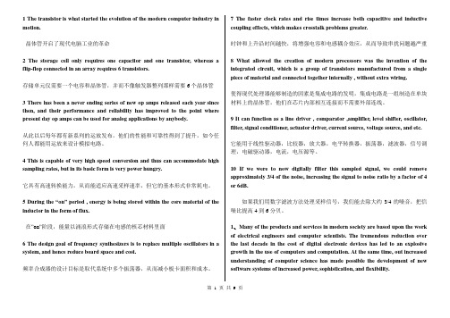
1 The transistor is what started the evolution of the modern computer industry in motion.晶体管开启了现代电脑工业的革命2 The storage cell only requires one capacitor and one transistor, whereas a flip-flop connected in an array requires 6 transistors.存储单元仅需要一个电容和晶体管,并而不像触发器整列那样需要6个晶体管3 There has been a never ending series of new op amps released each year since then, and their performance and reliability has improved to the point where present day op amps can be used for analog applications by anybody.从此以后每年都有新系列的运放发布,他们的性能和可靠性得到了提升,如今任何人都能用运放来设计模拟电路。
4 This is capable of very high speed conversion and thus can accommodate high sampling rates, but in its basic form is very power hungry.它具有高速转换能力,从而能适应高速采样速率,但它的基本形式非常耗电。
5 During the “on” period , energy is being stored within the core material of the inductor in the form of flux.在”on”阶段,能量以涌浪形式存储在电感的核芯材料里面6 The design goal of frequency synthesizers is to replace multiple oscillators in a system, and hence reduce board space and cost.频率合成器的设计目标是取代系统中多个振荡器,从而减小板卡面积和成本。
电子信息专业英语
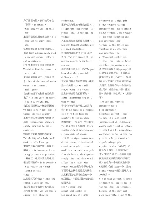
为了测量电阻,我们使用单位“欧姆”。
To measure resistance,we use the unit "ohm".重要的是要应用这些定律。
It is important to apply these laws. 这种装置能用来测量电流电压电阻。
Such a device can be used to measurecurrent,voltage and resistance. 我们想要求这个电流中的电流。
We wish to find the current in the circuit.无线电波的用途之一是发送信息。
One of the uses of radio waves is to transmit intelligence.在这种情况下该物体被说成带电了。
In this case the object is said to be charged.我们感到理解这个概念很困难。
We find it very difficult to understand this concept.工科学生应该知道如何使用计算机。
Engineering studentsshould know how to use acomputer.物体做工的能力被称为能量。
The ability of a body to do workis called energy.重要的是我们要把理论应用于实践。
It is important for us toapply theory to practice.计算在这个电流中流动的电流密度是可能的。
It is possible tocalculate the current flowing inthis circuit.这些是常用的设备。
These arecommonly used devices.电压等取决于电路中的电阻以及所加的电压。
Voltage equalscurrent multiplied byresistance.显然电流与外加电压成正比。
信息科学与电子工程专业英语翻译(第9、11单元)

Unit 9 数字信号和信号处理Unit 9-1第一部分:数字信号处理数字信号处理(DSP)是研究数字表示的信号以及这些信号的处理方法。
数字信号处理和模拟信号处理是信号处理的子领域。
数字信号处理包括音频及语音信号处理、声纳和雷达信号处理、传感器阵列处理、谱估计、统计信号处理、图像处理、通信信号处理、生物医学信号处理等子领域。
数字信号处理的目标通常是测量连续的真实世界的模拟信号或对其滤波,因此,第一步常常是使用模数转换器将信号从模拟形式转换成数字形式。
通常,要求的输出信号为另一个模拟输出信号,这就需要数模转换器。
数字信号处理的算法有时通过使用专用计算机来实现,它们(专用计算机)利用被称为数字信号处理器的专用微处理器(简称DSP)。
这些数字信号处理器实时处理信号,通常是针对具体目的而设计的专用集成电路(ASIC)。
当灵活性和快速开发比大批量生产的成本更重要时,DSP算法也可以用现场可编程门阵列来实现。
数字信号处理域在数字信号处理中,工程师通常在下面几个域的一个域中来研究数字信号:时域(一维信号),空域(多维信号),频域,自相关域以及小波域。
他们按照某些依据来猜测(或试验不同的可能性)那一个域能够最好地表示信号的本质特性来选择在其中进行信号处理的域。
从测量设备得到的样本序列产生(信号的)时域或空域表示,而离散Fourier变换则产生频域表示即频谱。
自相关定义为信号与其自身经过时间或空间间隔变化后的互相关。
信号采样随着计算机应用的增长,数字信号处理的使用和需求日益增多。
为了能够在计算机上使用模拟信号,必须使用模数转换器(ADC)对其进行数字化。
采样通常分两步实现:离散化和量化。
在离散化阶段,信号空间被分割为相等的区间,用相应区间的代表性信号值代替信号本身。
在量化阶段,用有限集中的值来近似代表性的信号值。
为了能够正确地重建被采样的模拟信号,必须满足奈奎斯特-香农采样定理。
定理规定:采样频率必须大于两倍的信号带宽。
(完整版)电子技术专业英语
1、汉译英1)直流电路direct current circuits2)放大器(扩音器)amplifier3)模拟电子技术analog electronics4)半导体二极管semiconductor diode5)晶体管效应transistor effect6)微处理器microprocessor7)电气工程electrical engineering8)能源工程(或电力工程)power engineering9)通信工程telecommunications engineering10)内部器件internal devices11)电子元件electrical components12)欧姆定律Ohm law13)限制电流limit current14)分压器voltage divider15)晶体管偏置电路transistor biasing circuits16)阻碍电流block DC current17)存储点能store electrical energy18)感抗inductive reactance19)绝缘材料insulating material20)交流阻抗AC resistancea)通用仪表general-purpose meterb)模拟仪表analog meterc)交换测试笔reverse the test leadsd)机械调节mechanical adjuste)测量电阻measure resistancef)正向电压positive voltageg)测量电流measure currenth)电压幅度voltage amplitudei)双踪示波器dual-trace oscilloscopej)信号发生器signal generator21)PN结PN junction22)三极管bipolar transistor23)电子和空穴electron and hole24)稳压电源electronic power supply或steady DC voltage source25)桥式整流器bridge rectifier26)脉冲直流电pulsating DC27)二极管的正极anode of diode28)峰值电压peak voltage29)电容滤波器capacitor filter30)充电和放电charge and discharge31)稳压管Zener diode32)电器电子工程师学会IEEE(Institute of Electrical and Electronics Engineers)33)专业技术组织technical professional association34)基尔霍夫电压定律Kirchhoff’s V oltage Law35)电压源voltage sources36)电荷守恒定律the law of conservation of electric charge37)在每一瞬时at every instant of time38)元件两端的电压voltages across elements39)无线电传输radio transmission40)频率调制或调频frequency modulation41)频域the frequency domain42)线性电阻linear resistor43)调幅波形amplitude modulation wave44)专用集成电路(ASIC)45)快速时间响应fast response time46)有效信号valid signal47)十进制数字系统decimal system48)逻辑运算logic operation1)控制信号线the control bus2)中断线interrupt lines1)结构化语言structured language2)局部变量local variables3)副作用side effect4)汇编语言指令assembly language instructions1)静止图像still image2)阴极射线管,显像管CRT or the cathode ray tube3)像素pixel4)电子束electron beam2、英译汉1)assembler language汇编语言2)alternating current circuits交流电路3)passive electrical circuits无源电路4)three phase circuits三相电路5)digital electronics数字电子技术6)logic gates逻辑门7)3D virtual reality image三维虚拟图像8)computer programming计算机编程9)major in(在大学里)主修10)advanced programming techniques高级编程技术1)known as capacitive reactance称为容抗2)with units ohms单位为欧姆3)prevent device from burning out防止器件烧掉4)has an AC resistance to AC current对交流电流由阻抗5)adjustment with a screw用一个螺丝调节6)in the shape of a cylinder 呈圆柱形式7)block DC current,but pass AC current阻直流通交流8)to vary the inductance改变电感9)be given by the formula 由公式给出10)the RF amplifier 音频放大器1)analog multimeter模拟万用表2)extended range扩展范围3)specific meters特殊仪表4)includes the function and range switches具有功能及范围选择旋钮5)present an electronic picture呈现一幅电子图像6)display the voltage waveform显示电压波形7)appear on the screen在屏幕上出现8)phase relationships相位关系9)an example例如,作为一个例子10)in series with the circuit串连接入电路1)Semiconductor material半导体材料2)forward biased正向偏置3)depend on the external circuit resistance取决于外部电路的电阻4)excessive reverse-biased voltage过高的反偏电压5)is directly proportional to the amount ofbase current是正比于基极电流6)may even appear almost as a short几乎可看成是短路7)cause stability problems for a transistorcircuit引起晶体管电路的稳定性问题8)digital technology数字技术9)the most popular technology最常用的技术10)use two complementary typeset oftransistors N-channel and P-channel用两种互补型的晶体管——N沟道和P沟道1)equipment operation设备的运行2)device that converts AC into DC把交流电转换成直流电的器件3)the power lines电源线4)depending on the value of DC voltageneeded 根据所需要的直流电压值5) a half-wave rectifier平波整流器6)so as to produce a constant DC output从而产生一个稳定的直流输出7)in the negative side of the capacitor在电容的负极8)flow through the load流过负载9)in the forward-biased condition在加正向偏置电压的条件下10) a series(current-limiting)resistor一个串联(限制电流)电阻1)current source电流源2)under this circumstance在这种情况下3)present the second of Kirchhoff’s laws给出基尔霍夫第二定律4)introduce the concept of a “loop”引入“回路”的概念5)An alternative statement of KVLKVL的另一种表述法6)voltages algebraically sum电压代数和7)sinusoidal steady-syate response正弦稳态响应8)ordinary household voltage日常用电的电压9)time-invariant circuit时不变电路10)percentage of modulation调制百分比reduce the power consumption减小消耗功率flip-flop 触发器the octal and hexadecimal systems当时钟脉冲信号来到时改变状态①直流电路direct current circuits②放大器(扩音器)amplifier③欧姆定律Ohm law④正极positive electrode⑤充电与放电Charge and discharge⑥无线电传输Radio transmission⑦模拟仪表Analogue Meters⑧模拟电子技术analog electronics⑨半导体二极管semiconductor⑩晶体管效应transistor effect⑪微处理器microprocessor⑫通信工程telecommunications engineering ⑬汇编语言assembler language⑭电子元件electrical components⑮限制电流limit current⑯分压器voltage divider⑰偏置电路biasing circuits⑱阻碍电流block DC current⑲感抗inductive reactance⑳容抗capacitive21正向电压positive voltage22扩展范围extended range23电压波形voltage waveform24连接入电路in series with the circuit25PN结PN junction 26三极管bipolar transistor27电子与空穴electron and hole28半导体材料semiconductor material29正向偏置forward biased30数字技术digital technology31桥式整流器bridge rectifier32稳压管Zener diode33电源线the power lines34在电容的负极in the negative side of the capacitor 在加正向偏置的条件下in the forward-biased condition一个串联电阻 a series (current-limiting)resistor35电压源voltage sources36在每一瞬时at every instant of time37无线电传输radio transmission38频率调制或调频frequency modulation39快速时间响应fast response time40有效信号valid signal41结构化语言structured language42局部变量local variables43副作用side effect44静止图像still image45阴极射线管pixel46电子束electron beam1.resistors are used to limit current flowing to adevice ,thereby preventing it from burning out, as voltage dividers to reduce voltage for other circuits, as transistor biasing circuits, and to serve as circuit loads.电阻常用做限流器,限制流过器件的电流防止烧坏器件,电阻也可用作分压器,以减小其他电路电压,还可以用在晶体管偏执电路中和作为电路负载。
- 1、下载文档前请自行甄别文档内容的完整性,平台不提供额外的编辑、内容补充、找答案等附加服务。
- 2、"仅部分预览"的文档,不可在线预览部分如存在完整性等问题,可反馈申请退款(可完整预览的文档不适用该条件!)。
- 3、如文档侵犯您的权益,请联系客服反馈,我们会尽快为您处理(人工客服工作时间:9:00-18:30)。
Analog and Digital(模拟电子和数字电子):Analog and DigitalIdeal Operational Amplifiers and Practical LimitationsIn order to discuss the ideal parameters of operational amplifiers, we must first define the terms, and then go on to describe what we regard as the ideal values for those terms. At first sight, the specification sheet for an operational amplifier seems to list a large number of values, some in strange units, some interrelated, and often confusing to those unfamiliar with the subject. The approach to such a situation is to be methodical, and take the necessary time to read and understand each definition in the order that it is listed. Without a real appreciation of what each means, the designer is doomed to failure. The objective is to be able to design a circuit from the basis of the published data, and know that it will function as predicted when the prototype is constructed.1It is all too easy with linear circuits, which appear relatively simple when compared with today‟s complex logic arrangements, to ignore detailed performance parameters which can drastically reduce the expected performance.Let us take a very simple but striking example. Consider a requirement for an amplifier having a voltage gain of 10 at 50 kHz driving into a 10 k load. A common low-cost, internally frequency-compensated op amp is chosen; it has the required bandwidth at a closed-loop gain of 10, and it would seem to meet the bill. The device is connected, and it is found to have the correct gain. But it will only produce a few volts output swing when the data clearly shows that the output should be capable of driving to within two or three volts of the supply rails. The designer has forgotten that the maximum output voltage swing is severely limited by frequency, and that the maximum low-frequency output swing becomes limited at about 10 kHz. Of course, the information is in fact on the data sheet, but its relevance has not been appreciated. This sort of problem occurs regularly for the inexperienced designer. So the moral is clear: always take the necessary time to write down the full operating requirements before attempting a design. Attention to the detail of the performance specification will always be beneficial. It is suggested the following list of performance details be considered:1. Closed loop gain accuracy, stability with temperature, time and supply voltage2. Power supply requirements, source and load impedances, power dissipation3. Input error voltages and bias currents. Input and output resistance, drift withtime and temperature4. Frequency response, phase shift, output swing, transient response, slew rate,frequency stability, capacitive load driving, overload recovery5. Linearity, distortion and noise6. Input, output or supply protection required. Input voltage range,common-mode rejection7. External offset trimming requirementNot all of these terms will be relevant, but it is useful to remember that it is better to consider them initially rather than to be forced into retrospective modifications.All parameters are subject to wide variationsNever forget this fact. How many times has a circuit been designed using typical values, only to find that the circuit does not work because the device used is not typical? The above statement thus poses a tricky question: when should typical values and when should worst-case values be used in the design? This is where the judgment of the experienced designer must be brought to bear. Clearly, if certain performance requirements are mandatory, then worst-case values must be used. In many cases, however, the desirability of a certain defined performance will be a compromise between ease of implementation, degree of importance, and economic considerations. Do not over-specify or over-designIn the end, we are all controlled by cost, and it is really pointless taking a sledgehammer to crack a nut, Simplicity is of the essence since the low parts count implementation is invariably cheaper and more reliable.As an example of this judgment about worst-case design, consider a low-gain DC transducer amplifier required to amplify 10 mV from a voltage source to produce an output of .l V with an accuracy of ±1% over a temperature range of 0~70︒C. Notice that the specification calls for an accuracy of ±1%. This implies that the output should be 1 V ±10 mV from 0 ~ 70︒C. The first step is, of course, to consider our list above, and decide which of the many parameters are relevant. Two of the most important to this (very limited) specification are offset voltage drift and gain stability with temperature. We will assume that all initial errors are negligible (rarely the case in practice). The experienced designer would know that most op amps have a very large open-loop gain, usually very much greater than 10000. A closed-loop gain change of ±1% implies that the loop gain (as explained later) should change by less than ±100% for a closed-loop gain of 100. This is clearly so easily fulfilled that the designer knows immediately that he can use typical open-loop gain values in his calculations. However, offset voltage drift is another matter. Many op amp specifications include only typical values for offset voltage drift; this may well be in the order of 5 μV/︒C, with an unquoted maximum for any device of 30 μV/︒C. If by chance we use a device which has this worst-case drift, then the amplifier error could be 30×70=2100 μV=2.1 mV over temperature, which is a significant proportion of our total allowable error from all sources.Here is a case, then, where one can be confident that the typical value of open-loop gain can be used, but where the maximum value of drift may well cause significant errors. This sort of judgment is essential in careful design, and great care is required in interpreting manufacturers‟ data. This consideration must be ext ended toall the details listed above apart from the fact that worst-case values are often not quoted. It is often found that values given are not 100% tested. Statistical testing is employed which, for example, guarantees that 90% of all devices fall within the range specified. It could be very inconvenient for the user who relies on the specified performance and then finds that he has several of the …other‟ 10% actually plugged into his circuit.Data Registers and CountersData registerThe simplest type of register is a data register, which is used for the temporary storage of a “word” of data. In its simplest form, it consists of a set of N D flip-flops, all sharing a common clock. All of the digits in the N bit data word are connected to the data register by an N-line “data bus”. Figure 1.1 shows a 4 bit data register, implemented with four D flip-flops. The data register is said to be a synchronous device, because all the flip-flops change state at the same time.Shift registersAnother common form of register used in computers and in many other types of logic circuits is a shift register. It is simply a set of flip-flops (usually D latches or RS flip-flops) connected together so that the output of one becomes the input of the next, and so on in series. It is called a shift register because the data is shifted through the register by one bit position on each clock pulse. Figure 1.2 shows a 4 bit shift register, implemented with D flip-flops.On the leading edge of the first clock pulse, the signal on the DATA input is latched in the first flip-flop. On the leading edge of the next clock pulse, the contents of the first flip-flop is stored in the second flip-flop, and the signal which is present at the DATA input is stored in the first flip-flop, etc. Because the data is entered one bit at a time, this called a serial-in shift register. Since there is only one output, and data leaves the shift register one bit at a time, then it is also a serial out shift register. (Shift registers are named by their method of input and output; either serial or parallel.) Parallel input can be provided through the use of the preset and clear inputs to the flip-flop. The parallel loading of the flip-flop can be synchronous (i.e., occurs with the clock pulse) or asynchronous (independent of the clock pulse) depending on the design of the shift register. Parallel output can be obtained from the outputs of each flip-flop as shown in Figure 1.3.Communication between a computer and a peripheral device is usually done serially, while computation in the computer itself is usually performed with parallel logic circuitry. A shift register can be used to convert information from serial form to parallel form, and vice versa. Many different kinds of shift registers are available, depending upon the degree of sophistication required.Counters — weighted coding of binary numbersIn a sense, a shift register can be considered a counter based on the unary numbersystem. Unfortunately, a unary counter would require a flip-flop for each number in the counting range. A binary weighted counter, however, requires only flip-flops to count to N. A simple binary weighted counter can be made using T flip-flops. The flip-flops are attached to each other in a way so that the output of one acts as the clock for the next, and so on. In this case, the position of the flip-flop in the chain determines its weight; i.e., for a binary counter, the “power of two” it corresponds to.A 3-bit (modulo 8) binary counter could be configured with T flip-flops as shown in Figure 1.4. A timing diagram corresponding to this circuit is shown in Figure 1.5.Note that a set of lights attached to O0, O1, O2 would display the numbers of full clock pulses which had been completed, in binary (modulo 8), from the first pulse. As many T flip-flops as required could be combined to make a counter with a large number of digits.Note that in this counter, each flip-flops changes state on the falling edge of the pulse from the previous flip-flop. Therefore there will be a slight time delay, due to the propagation delay of the flip-flops between the time one flip-flop changes state and the time the next one changes state, i.e., the change of state ripples through the counter, and these counters are therefore called ripple counters. As in the case of a ripple carry adder, the propagation delay can become significant for large counters.It is possible to make, or buy in a single chip, counters which will count up, count down, and which can be preset to any desired number. Counters can also be constructed which count in BCD and base 12 or any other number base.A count down counter can be made by connecting the Q output to the clock input in the previous counter. By the use of preset and clear inputs, and by gating the output of each T flip- flop with another logic level using AND gates (say logic 0 for counting down, logic 1 for counting up), then a presetable up-down binary counter can be constructed. Figure 1.6 shows an up-down counter, without preset or clear.Synchronous countersThe counters shown previously have been “asynchronous counters”; so called because the flip-flops do not all change state at the same time, but change as a result of a previous output. The output of one flip-flop is the input to the next; the state changes consequently “ripple through” the flip-flops, requiring a time proportional to the length of the counter. It is possible to design synchronous counters, using JK flip-flops, where all flip-flops change state at the same time; i.e., the clock pulse is presented to each JK flip-flop at the same time. This can be easily done by nothing that, for a binary counter, any given digit changes its value (from 1 to 0 or from 0 to 1) whenever all the previous digits have a value of 1. A count down timer can be made by connecting the Q output to the J and K, through the AND gates. Preset and clear could also be provided, and the counter could be made “programmable” as in the previous case.The timing diagram is similar to that shown for the asynchronous (ripple) counters, except that the ripple time is now zero; all counters clock at the same time. It is common for synchronous counters to trigger on the positive edge of the clock,rather than the trailing edge.Nature of Phase LockThe phase detector compares the phase of a periodic input signal against the phase of the VCO. Output of PD is a measure of the phase difference between its two inputs. The difference voltage is then filtered by the loop filter and applied to the VCO. Control voltage on the VCO changes the frequency in a direction that reduces the phase difference between the input signal and the local oscillator.When the loop is locked, the control voltage is such that the frequency of the VCO is exactly equal to the average frequency of the input signal. For each cycle of input there is one, and only one, cycle of oscillator output. One obvious application of phase lock is in automatic frequency control (AFC). Perfect frequency control can be achieved by this method, whereas conventional AFC techniques necessarily entail some frequency error.To maintain the control voltage needed for lock it is generally necessary to have a nonzero output from the phase detector. Consequently, the loop operates with some phase error present. As a practical matter, however, this error tends to be small in a well-designed loop.A slightly different explanation may provide a better understanding of loop operation. Let us suppose that the incoming signal carries information in its phase or frequency; this signal is inevitably corrupted by additive noise. The task of a phase lock receiver is to reproduce the original signal while removing as much of the noise as possible.To reproduce the signal the receiver makes use of a local oscillator whose frequency is very close to that expected in the signal. Local oscillator and incoming signal waveforms are compared with one another by a phase detector whose error output indicates instantaneous phase difference. To suppress noise the error is averaged over some length of time, and the average is used to establish frequency of the oscillator.If the original signal is well behaved (stable in frequency), the local oscillator will need very little information to be able to track, and that information can be obtained by averaging for a long period of time, thereby eliminating noise that could be very large. The input to the loop is a noisy signal, whereas the output of the VCO is a cleaned-up version of the input. It is reasonable, therefore, to consider the loop as a kind of filter that passes signals and rejects noise.Two important characteristics of the filter are that the bandwidth can be very small and that the filter automatically tracks the signal frequency. These features, automatic tracking and narrow bandwidth, account for the major uses of phase lock receivers. Narrow bandwidth is capable of rejecting large amounts of noise; it is not at all unusual for a PLL to recover a signal deeply embedded in noise.History and applicationAn early description of phase lock was published by de Bellescize in 1932 and treated the synchronous reception of radio signals. Superheterodyne receivers hadcome into use during the 1920s, but there was a continual search for a simpler technique; one approach investigated was the synchronous, or homodyne, receiver. In essence, this receiver consists of nothing but a local oscillator, a mixer, and an audio amplifier. To operate, the oscillator must be adjusted to exactly the same frequency as the carrier of the incoming signal, which is then converted to an intermediate frequency of exactly 0 Hz. Output of the mixer contains demodulated information that is carried as sidebands by the signal. Interference will not be synchronous with the local oscillator, and therefore mixer output caused by an interfering signal is a beat-note that can be suppressed by audio filtering.Correct tuning of the local oscillator is essential to synchronous reception; any frequency error whatsoever will hopelessly garble the information. Furthermore, phase of the local oscillator must agree, within a fairly small fraction of a cycle, with the received carrier phase. In other words, the local oscillator must be phase locked to the incoming signal.For various reasons the simple synchronous receiver has never been used extensively. Present-day phase lock receivers almost invariably use the superheterodyne principle and tend to be highly complex. One of their most important applications is in the reception of the very weak signals from distant spacecraft. The first widespread use of phase lock was in the synchronization of horizontal and vertical scan in television receivers. The start of each line and the start of each interlaced half-frame of a television picture are signaled by a pulse transmitted with the video information. As a very crude approach to reconstructing a scan raster on the TV tube, these pulses can be stripped off and individually utilized to trigger a pair of single sweep generators.A slightly more sophisticated approach uses a pair of free-running relaxation oscillators to drive the sweep generators. In this way sweep is present even if synchronization is absent.Free-running frequencies of the oscillators are set slightly below the horizontal and vertical pulse rates, and the stripped pulses are used to trigger the oscillators prematurely and thus to synchronize them to the line and half-frame rates (half-frame because United States television interlaces the lines on alternate vertical scans).In the absence of noise this scheme can provide good synchronization and is entirely adequate. Unfortunately, noise is rarely absent, and any triggering circuit is particularly susceptible to it. As an extreme, triggered scan will completely fail at a signal-to-noise ratio that still provides a recognizable, though inferior, picture.Under less extreme conditions noise causes starting-time jitter and occasional misfiring far out of phase. Horizontal jitter reduces horizontal resolution and causes vertical lines to have a ragged appearance. Severe horizontal misfiring usually causes a narrow horizontal black streak to appear.Vertical jitter causes an apparent vertical movement of the picture. Also, the interlaced lines of successive half-frames would so move with respect to one another that further picture degradation would result.Noise fluctuation can be vastly reduced by phase locking the two oscillators to the stripped sync pulses. Instead of triggering on each pulse a phase-lock techniqueexamines the relative phase between each oscillator and many of its sync pulses and adjusts oscillator frequency so that the average phase discrepancy is small.Because it looks at many pulses, a phase lock synchronizer is not confused by occasional large noise pulses that disrupt a triggered synchronizer. The flywheel synchronizers in present day TV receivers are really phase-locked loops. The name “flywheel” is used because the circuit is able to coast through periods of increased noise or weak signal. Substantial improvement in synchronizing performance is obtained by phase-lock.In a color television receiver, the color burst is synchronized by a phase-lock loop.Space flight requirements inspired intensive application of phase lock methods. Space use of phase lock began with the launching of the first American artificial satellites. These vehicles carried low-power (10 mW) CW transmitters; received signals were correspondingly weak. Because of Doppler shift and drift of the transmitting oscillator, there was considerable uncertainty about the exact frequency of the received signal. At the 108 MHz frequency originally used, the Doppler shift could range over a ±3 kHz interval.With an ordinary, fixed-tuned receiver, bandwidth would therefore have to be at least 6 kHz, if not more. However, the signal itself occupies a very narrow spectrum and can be contained in something like a 6 Hz bandwidth.Noise power in the receiver is directly proportional to bandwidth. Therefore, if conventional techniques were used, a noise penalty of 1000 times (30 dB) would have to be accepted. The numbers have become even more spectacular as technology has progressed; transmission frequencies have moved up to S-band, making the Doppler range some ±75 kHz, whereas receiver bandwidths as small as 3 Hz have been achieved. The penalty for conventional techniques would thus be about 47 dB. Such penalties are intolerable and that is why narrowband, phase-locked, tracking receivers are used.Noise can be rejected by a narrowband filter, but if the filter is fixed the signal almost never will be within the pass-band. For a narrow filter to be usable it must be capable of tracking the signal. A phase-locked loop is capable of providing both the narrow bandwidth and the tracking that are needed. Moreover, extremely narrow bandwidths can be conveniently obtained (3 to 1000 Hz are typical for space applications); if necessary, bandwidth is easily changed.For a Doppler signal the information needed to determine vehicle velocity is the Doppler shift. A phase-lock receiver is well adapted to Doppler recovery, for it has no frequency error when locked.Other applicationsThe following applications, further discussed elsewhere in the book, represent some of the current uses of phase-lock.1. One method of tracking moving vehicles involves transmitting a coherentsignal to the vehicle, offsetting the signal frequency, and re-transmitting back to the ground. The coherent transponder in the vehicle must operate so that the input and output frequencies are exactly related in the ratio m/n, where m and nare integers. Phase-lock techniques are often used to establish coherence.2. A phase-locked loop can be used as a frequency demodulator, in which it hassuperior performance to a conventional discriminator.3. Noisy oscillators can be enclosed in a loop and locked to a clean signal. If theloop has a wide bandwidth, the oscillator tracks out its own noise and its output is greatly cleaned up.4. Frequency multipliers and dividers can be built by using PLLs.5. Synchronization of digital transmission is typically obtained by phase-lockmethods.6. Frequency synthesizers are conveniently built by phase-lock loops.中文翻译:模拟电子和数字电子理想运算放大器和实际限制为了讨论运算放大器的理想参数,我们必须首先定义一些指标项,然后对这些指标项讲述我们所认为的理想值。