Experimental validation of PID based cascade control system through SCADA-PLC-OPC interface
自动送料机控制系统设计毕业论文
自动送料机控制系统设计毕业论文让我来给你提供一些关于自动送料机控制系统设计的毕业论文的思路和段落结构。
1. Introduction介绍自动送料机控制系统的背景和意义,说明自动送料机在工业生产中的重要性,以及设计一个高效可靠的控制系统对于提高生产效率和质量的意义。
2. Literature Review综述现有的自动送料机控制系统设计方法和技术,包括传统的PID控制方法以及现代控制理论中的模型预测控制和自适应控制等方法。
对各种方法的优缺点进行分析和比较。
3. System Modeling对自动送料机进行数学建模,建立动力学模型。
可以考虑使用系统辨识技术,从实际运行数据中提取模型参数,或者基于物理原理和传感器测量数据建立模型。
4. Control System Design基于建立的系统模型,设计自动送料机的控制系统。
可以选择合适的控制方法,如PID控制、模型预测控制等,并设计合适的控制器结构和参数。
5. Simulation and Analysis通过数值模拟和仿真实验,验证控制系统设计的性能。
比较不同控制方法的性能优劣,分析控制系统的稳定性、鲁棒性和性能指标等。
6. Hardware Implementation将控制系统在自动送料机的实际硬件平台上进行实现和集成,包括传感器、执行机构和控制器等部件的配置和连接。
7. Experimental Validation在实际工作场景中进行试验验证,对比实验结果与仿真结果,评估控制系统在实际工作环境中的性能和可靠性。
8. Conclusion总结研究工作,回顾控制系统设计的目标和方法,总结主要研究结果和创新点。
讨论研究的局限性和未来的改进方向。
这是一个简单的论文结构框架,你可以根据自己的实际情况进行修改和完善。
在每个章节中,可以根据具体内容添加故障诊断、控制策略优化等相关内容。
希望对你的论文写作有所帮助!。
PNA-FISH-探针
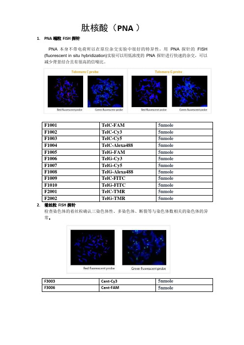
1.PNA 端粒FISH 探针肽核酸(PNA )PNA 本身不带电荷所以在原位杂交实验中很好的特异性,用PNA 探针的FISH (fluorescent in situ hybridization)实验可以用低浓度的PNA 探针进行快速的杂交,可以减少背景结合且有很高的信噪比。
F1001 TelC-FAM5nmoleF1002 TelC-Cy3 5nmoleF1003 TelC-Cy5 5nmoleF1004 TelC-Alexa488 5nmoleF1005 TelG-FAM 5nmoleF1006 TelG-Cy3 5nmoleF1007 TelG-Cy5 5nmoleF1008 TelG-Alexa488 5nmoleF1009 TelC-FITC 5nmoleF1010 TelG-FITC 5nmoleF2001 TelC-TMR 5nmoleF2002 TelG-TMR 5nmole2.着丝粒FISH 探针检查染色体的着丝粒确认三染色体性、多染色体、断裂等与染色体数相关的染色体的异常。
F3003 Cent-Cy3 5nmoleF3006 Cent-FAM 5nmole参考文献(端粒FISH 探针和着丝粒FISH 探针):1Kentaro Taemura et al., Dynamic rearrangement of telomeres during spermatogenesis in mice. Developmental Biology. 2005;281:196-207.2Won-Woo Lee et al., Age-related telomere length dynamics in peripheral blood mononuclear cells of healthy cynomolgus monkeys measured by Flow FISH. Immunology. 2002;105:458-465.3Heather Perry et al., Identification of indicator microorganisms using a standardized PNA FISH method. Journal of Microbiological Methods 2001;47:281-292.4Caifu Chen et al., Single base discrimination of CENP-B repeats on mouse and human chromosomes with PNA-FISH. Mammalian Genome. 1999;10:13-18.5M. Hultdin et al., Telomere analysis by flourescence in situ hybridization and flow cytometry. Nucleic Acids Research. 1998;26(16):3651-3656.6Peter M. Landsdorp et al., Heterogeneity in telomere length of human chromosomes. Human Molecular Genetics. 1996;5(5):685-691.3.PNA oligomers for PCR clamping 球蛋白抑制剂血液内存在的mRNA 的70%以上是球蛋白mRNA,显著减少基因的发现分析及敏感度。
高热通量水平管外池沸腾传热

高热通量水平管外池沸腾传热冀文涛;张定才;赵创要;何雅玲;陶文铨【摘要】For the flooded evaporator in refrigeration or air conditioning systems,refrigerant is boiling on the shell side and water is flowing in the tube side.The pool boiling heat transfer coefficient of R134a outside one smooth tube and one reentrant cavity enhanced tube No.1 is investigated with an experimental approach.At the saturate temperature of 6,10 and 16℃,the heat flux of 10-250 kW · m-2,the heat transfer coefficient versus heat flux of smooth tube is investigated and compared with Cooper correlation.The external diameter of smooth tube and enhanced tube are 15.93 mm and 25.36 mm,respectively.At the heat flux of 10-250 kW · m-2,it is found that the deviation of experimental result and Cooper correlation is within ± 15%.the average value of m in h ∝qm,is 0.67.For the enhanced tube,the enhanced ratio is the largest at the heat flux less than 40 kW · m-2.The enhanced ratio is decreasing as the increment of heat flux.At the heat flux larger than 250 kW · m-2,the heat transfer coefficient of enhanced tube is approaching the smooth tube,and even smaller than smooth tube.%在制冷空调的满液式蒸发器中,制冷剂在壳侧沸腾蒸发,管内为水的单相对流传热.实验研究了高热通量下R134a在一根光管和一根强化管(No.1)外的池沸腾传热,并将光管实验结果和Cooper公式进行了比较.在不同的饱和温度下,热通量10~250 kW·m-2的范围内,研究了R134a在光管和强化管外的沸腾传热系数随热通量的变化关系.光管和强化管外径分别为15.93 mm和25.36 mm.通过研究发现,在热通量10~250 kW·m-2的范围内,光管的池沸腾传热系数和Cooper公式符合较好,偏差小于±15%.在双对数坐标下传热系数和热通量实验结果拟合直线斜率为0.67.在较高热通量,即热通量大于250 kW·m-2时,光管的传热系数相对Cooper公式偏差开始增大.对于高效管,在小于40kW·m-2热通量下的传热效果最好.强化管的强化倍率随热通量增加一直减小,在较高热通量250 kW· m-2下,强化管的传热系数和光管相同,甚至比光管小.【期刊名称】《化工学报》【年(卷),期】2016(067)0z1【总页数】5页(P28-32)【关键词】池沸腾;热通量;饱和温度;传热系数;强化管【作者】冀文涛;张定才;赵创要;何雅玲;陶文铨【作者单位】西安交通大学能源与动力工程学院,热流科学与工程教育部重点实验室,陕西西安710049;中原工学院能源与环境学院,河南郑州450007;西安交通大学能源与动力工程学院,热流科学与工程教育部重点实验室,陕西西安710049;西安交通大学能源与动力工程学院,热流科学与工程教育部重点实验室,陕西西安710049;西安交通大学能源与动力工程学院,热流科学与工程教育部重点实验室,陕西西安710049【正文语种】中文【中图分类】TK124池沸腾传热广泛应用于制冷空调领域。
基于MCGS组态软件的PID液位控制

2008年8月第14卷第3期安庆师范学院学报(自然科学版)Journal of Anqing Teachers College (Natural Science Edition )Aug.2008Vol.14No.3基于MCGS 组态软件的PID 液位控制吴文进,张 杰(安庆师范学院物理与电气工程学院,安徽安庆246133) 摘 要:以T HJ -2高级过程控制实验装置为基础,采用串级PID 控制方法设计建立了双容水箱的数学模型,构成了以上水箱液位为副参数、下水箱液位为主参数的液位串级控制系统,在组态软件MCGS 中进行了实现,实验测试结果表明,系统实现了对过程参数的无稳态误差控制,具有良好的稳态性能和动态性能。
关键词:液位;串级控制;PID 控制;组态软件中图分类号:TP273 文献标识码:A 文章编号:1007-4260(2008)03-0050-04图1 双容水箱 0 引言液位控制问题是工业生产过程中的一类常见问题,例如在饮料、食品加工、溶液过滤、化工生产等多种行业的生产加工过程中都需要对液位进行适当的控制。
通过液位的检测与控制,可以了解容器中的原料 半成品或成品的数量,以便调节容器内的输入输出物料的平衡,保证生产过程中各环节的物料搭配得当[1]。
通过控制计算机可以不断监控生产的运行过程,即时显示容器的液位,保证产品的质量和数量。
本文将以T HJ -2高级过程控制实验装置为基础,采用串级PID 控制方法来设计液位控制方案,并利用MC GS 组态软件来实现计算机监控,使控制系统具有良好的稳态性能和动态性能。
1 被控对象建模图1是两个串联单容水箱构成的双容水箱,其输入量为调节阀1产生的阀门开度变化△u ,而输出量为第二个水箱的液位增量△h 2。
文献[2,3]中详细推出了双容水箱的传递函数:G (S )=△H 2(S )△U (S )=K T 1T 2S2+(T 1+T 2)S +1=K 13K 2(T 1s +1)(T 2s +1)(1)其中K 1和K 2为两个水箱的传递系数。
计算机网络中隐私信息安全存储系统整体架构设计及仿真实验验证研究
第19期2023年10月无线互联科技Wireless Internet Science and TechnologyNo.19October,2023作者简介:汤培新(1979 ),男,广东广州人,工程师,本科;研究方向:网络安全和数据安全㊂计算机网络中隐私信息安全存储系统整体架构设计及仿真实验验证研究汤培新(广州市人力资源和社会保障数据服务中心,广东广州510000)摘要:信息技术的快速发展带动了计算机在各行各业中的高度应用,但计算机网络在运行中仍存在一定的安全风险,如黑客攻击㊁网络漏洞等,造成用户隐私信息安全受到威胁㊂基于此,文章提出一种基于Linux 系统的隐私信息安全存储系统,从系统整体设计与功能模块设计两方面出发,将隐私信息安全存储系统分为控制平面与数据平面两大版块,同时设计网络报文处理模块功能与数据加密模块功能,以期通过各功能模块的协同配合,增强网络隐私信息安全处理效果,实现计算机网络中隐私信息的安全存储㊂将文章研究的存储系统与基于SAN 技术和基于Modbus /TCP 的隐私信息安全存储系统进行仿真实验验证,得出本系统对于隐私信息存储的安全性和处理效率更高,且存储信息数据更为完整,存储空间也较小,适合实践推广应用㊂关键词:计算机网络;隐私信息安全存储系统;Linux 系统中图分类号:TP333㊀㊀文献标志码:A0㊀引言㊀㊀目前,信息数据的隐私安全已成为计算机网络领域中的研究热点㊂董子渔[1]提出一种基于SAN 技术的隐私信息安全存储系统,通过采用SAN 网络框架,将网络信息安全存储系统划分为管理调控模块㊁资源池模块㊁安全控制模块以及网络安全模块,通过各模块间的调度与协作,实现了隐私数据的储存与管理,有效提高了数据安全保护效率㊂但在使用中,该方法也存在存储量受限的问题,导致系统无法及时更新㊂许建峰等[2]提出一种基于Modbus /TCP 的隐私信息安全存储系统,在硬件方面优化计算机网络的网关,实现了安全级DCS 与非安全级DCS 的Modbus /TCP 协议转换,并通过对安全信息进行加密传输和口令认证,实现信息安全存储㊂此系统在保证隐私数据安全存储效率的基础上,降低了安全检测的读带宽和写带宽,使系统能够同时执行更多的安全存储任务㊂但在使用中,该系统也存在无法压缩数据的缺点,造成该系统占用计算机网络空间较大的问题㊂基于此,本研究通过提出一种基于Linux 系统的隐私信息安全存储系统,通过选取Linux 系统作为设计核心,最大限度地发挥数据加解密技术优势,以实现对iSCSI 报文携带数据的加解密处理,达到安全存储的最终目的,且所需存储空间更小,更适用于实践应用㊂1㊀隐私信息安全存储系统整体架构设计1.1㊀系统整体设计㊀㊀Linux 系统是一种基于自由和开放源代码的操作系统,具有较强的安全性与稳定性,可在多种应用平台上运行,并能为使用者提供众多应用程序的工具,以满足用户的实际操作需求㊂1.1.1㊀控制平面设计㊀㊀本系统控制平面设计时充分借助了Linux 系统的IPC 机制,即基于Netlink Socket 的内核态与用户态间的双向数据传输技术,实现了数据平面数据包的高速转发,切实提高了隐私信息安全存储系统的信息管理效率与报文处理效率[3]㊂结构如图1所示㊂1.1.2㊀数据平面设计㊀㊀数据平面CPU 在ZOL 核上运行,主要负责隐私信息安全存储系统的业务逻辑处理㊂按照系统业务需求的不同,数据平面CPU 共包括网络报文处理模块和3DES 加解密模块两大部分,二者分别以不同的进程进行㊂其中,网络报文处理进程负责为系统生产数据,数据加解密进程则负责对数据进行加解密处理,并在处理完成后,将数据复原为最原始的报文格式,再从网口发送出去[4]㊂在本系统中,将35个CPU 划分为30个CPU 进行数据包处理,5个CPU 进行数据加解密处理,以构建出性能最佳的CPU 分配比例㊂且两个进程所使用的CPU 数量也可根据系统的实际需求进行动态调整,使渠道隐私信息安全存储系统处于最佳工作状态㊂1.2㊀功能模块设计1.2.1㊀网络报文处理模块功能设计㊀㊀网络报文处理模块作为隐私信息安全存储系统的功能模块之一,既负责从网口接收的报文中提取IPSAN 系统传输的数据;也负责将数据加解密模块处理后的数据复原成最初接收时的报文格式,再传输给mPIPE,从网口中发送出去㊂详细工作流程如图2所示㊂图1㊀控制平面CPU结构图2㊀网络报文处理模块流程㊀㊀(1)TCP 重组㊂TCP 重组是指信息系统在工作时,Linux 内核会依据网络拥塞情况,将一段较长的TCP 流分割成一定长度,然后再给其添加IP 头部,并重新计算校验,最后封装成IP 数据从网口发送出去㊂通过此流程,可有效避免数据丢失的情况发生,切实保证了隐私数据传输的安全性㊂(2)iSCSI 协议解析㊂因隐私信息安全存储系统只对IPSAN 系统传输的数据加解密,其他报文直接转发,所以iSCSI 协议解析的目的是从携带数据的iSCSI 报文中获取数据,其他报文并不做处理㊂在协议解析时,首选判定iSCSI 报文类型,若是直接进行登录操作㊁注销操作的iSCSI报文,则直接转发;若是携带数据的iSCSI 报文,则需获取携带的数据以及密钥索引(包括目标器名称㊁逻辑单元号等),最后将所涉及的隐私数据保存在网络缓存中,移交至加解密模块对数据进行加解密处理㊂1.2.2㊀数据加解密模块功能设计㊀㊀数据加解密模块的本质是通过复杂的加解密算法,对计算机网络中所传输的隐私数据进行加密处理㊂其模块流程如图3所示㊂从模块流程中可以看出,加解密模块首先从安全头获取密钥索引,然后再从密钥管理模块中查询密钥,最后将所查询到的密钥和数据一起传输到MiCA 引擎中进行加解密处理,以保证隐私数据的安全性㊂图3㊀数据加解密模块流程㊀㊀密钥构成及管理㊂本系统中,数据加解密模块的核心功能是通过密钥管理才得以实现的㊂即将解密报文中的3个域(Logic Block Address㊁Target ID㊁LUN ID)作为密钥索引从密钥管理模块中查询密钥,有效保证了密钥的安全性㊂且在系统中,通过将以上3个密钥索引作为随机数种子,调取Linux 系统的srand 函数生成一组192bit 随机字符串作为密钥,将密钥存储到SQLite 数据库中,可防止黑客攻击所造成的数据丢失,极大地提高了密钥安全性㊂在实际操作时,只需在计算机本地磁盘中保存一个映射表,就可从SQLite 数据库中查找到密钥索引所对应的密钥,完成数据加解密处理㊂2㊀隐私信息安全存储系统仿真实验验证㊀㊀为验证本文提出的基于Linux 系统的隐私信息安全存储系统的应用效果,将基于SAN 技术的信息安全存储系统与基于Modbus /TCP 的信息安全存储系统作为对照组,进行仿真实验验证㊂2.1㊀实验参数设定㊀㊀仿真实验参数设定为:发送信息时的比特数1bit㊁接收端与发送端之间的距离3000km㊁包速率3pkt/s㊁平均时延3ms㊁最大传输单位1200Byte㊁分组负载547bytes㊂2.2㊀存储量测试结果㊀㊀存储量在计算机数据结构中是指算法执行过程时所需的最大存储空间,也指在SQLite数据库中存储数据的多少,计算公式为:存储量=存储单位个数ˑ存储字长㊂设定主存地址寄存器为18位㊁主存数据寄存器为36位,在依据按字寻址范围为6k的情况下,测试不同隐私信息安全存储系统数据存储量㊂测试结果如图4所示㊂图4㊀3种隐私信息安全存储系统存储量测试结果㊀㊀从存储量数据结果中可以看出:第一,当按字寻址范围达到6000k时,本文所提出的基于Linux系统的隐私信息安全存储系统的存储量可达到60GB,基于SAN技术的信息安全存储系统存储量为54GB,基于Modbus/TCP的信息安全存储系统存储量为57 GB,大小排序为本文所提出的系统>基于Modbus/ TCP的系统>基于SAN技术的系统㊂第二,随着按字寻址范围的增大,本文所提出系统的存储量大小要普遍优于其他两种隐私信息安全存储系统㊂由此可见,本文所提出的基于Linux系统的隐私信息安全存储系统存储量要明显优于另外两个存储系统㊂根本原因在于本文所提出的隐私信息安全存储系统在设计初始,就通过设计数据加解密模块功能,对所要传输的隐私信息进行了加密与解密,以此提高了隐私信息数据存储量,避免了信息存储遗漏㊂2.3㊀系统内存测试结果㊀㊀隐私信息安全存储系统在运行时,CPU占用率越低,说明系统运行效果更好,表示系统具有较强的并发能力,可支持多个流程同时运行㊂设定最大储存数据大小为600GB,测试不同隐私信息安全存储系统CPU占用情况㊂测试结果如图5所示㊂图5㊀3种隐私信息安全存储系统系统内存测试结果㊀㊀从图5中可以看出,当计算机储存数据量达到600GB时,本文所提出的基于Linux系统的隐私信息安全存储系统的CPU占用速率为10.12%,基于SAN 技术的信息安全存储系统的CPU占用率为11.23%,基于Modbus/TCP的信息安全存储系统的CPU占用率为11.97%,且随着存储数据的增大,本文提出系统的CPU占用率要明显低于其他两个系统,说明基于Linux的系统具有较好的并发性能,能支持多个流程同时运行,保障了数据的顺利传输㊂3 结语㊀㊀综上所述,通过仿真实验验证可以得出,本文所设计的基于Linux系统的隐私信息安全存储系统,存储量较高为60GB,安全存储占用系统内存较低为10.12%㊂真正通过设计控制平面CPU和数据平面CPU的合理分配与网络报文处理模块与数据加解密模块的功能,实现了数据链的合理传输㊁数据的加密与解密,切实增强了计算机网络中隐私信息安全的存储效果,极大地提高了隐私信息的安全性,为通信传输提供了科学的安全保障,具有较强的实践推广价值㊂参考文献[1]董子渔.基于SAN技术的网络数据安全存储系统设计[J].信息与电脑(理论版),2021(18):209-211.[2]许建峰,许俊渊,方洪波.基于Modbus/TCP的发电厂DCS网关网络信息安全存储系统设计[J].现代电子技术,2022(2):115-119.[3]张小云,张增新.数据加密技术在网络数据信息安全中的应用[J].网络安全技术与应用,2023(4): 22-23.[4]杨晓娇,吴文博,董洁,等.大数据时代下的网络信息安全保护策略研究[J].数字通信世界,2023 (3):4-5,23.(编辑㊀王雪芬)Design and simulation experimental validation of the overall architecture ofprivacy information security storage system in computer networksTang PeixinGuangzhou Human Resources and Social Security Data Service Center Guangzhou510000 ChinaAbstract The rapid development of information technology has driven the high application of computers in various industries.However there are still certain security risks in the operation of computer networks such as hacker attacks network vulnerabilities etc.which pose a threat to the security of user privacy information.Based on this this article proposes a design of a privacy information secure storage system based on Linux system.Starting from the overall system design and functional module design the privacy information secure storage system is divided into two major sections control plane and data plane.At the same time two major functions are designed network message processing module and data encryption module.The aim is to collaborate and cooperate with each functional module Enhance the security processing effect of network privacy information and achieve secure storage of privacy information in computer networks.Finally simulation experiments were conducted to verify the proposed storage system with privacy information security storage systems based on SAN technology and Modbus/TCP.It was found that the system has better security and processing efficiency for privacy information storage and the stored information data is more complete with smaller storage space making it suitable for practical promotion and application.Key words computer network secure storage system for privacy information Linux system。
MicroRNA靶基因研究

microrna靶基因研究MicroRNAs (miRNAs)是一种大小约21—23个碱基的单链小分子RNA,是由具有发夹结构的约70-90个碱基大小的单链RNA前体经过dicer酶加工后生成,不同于siRNA(双链)但是和siRNA密切相关。
据推测,这些非编码小分子RNA(miRNAs)参与调控基因表达,但其机制区别于siRNA介导的mRNA降解。
第一个被确认的miRNA是在线虫中首次发现的lin-4 和let-7,随后多个研究小组在包括人类、果蝇、植物等多种生物物种中鉴别出数百个miRNAs。
最早被发现的两个miRNAs——lin-4 and let-7被认为是通过不完全互补结合到目标靶mRNA 3’非编码区端,以一种未知方式诱发蛋白质翻译抑制,进而抑制蛋白质合成,阻断mRNA的翻译。
多个果蝇miRNAs也被发现和他们的目标靶mRNAs的3’非编码区有部分同源。
由于miRNAs和其潜在的目标靶之间并非完全互补,这使得通过信息学的方法鉴定miRNA的目标靶位点变得困难。
因而也无法确定miRNAs的作用方式是什么,以何种机制影响mRNA的翻译,以何种方式调控基因表达。
miRNAs的作用目标靶和活性机制一直是各地的研究人员的关注热点。
总结了一些microrna靶基因方法的比较重要的文献,与大家共享。
()Combinatorial microRNA target predictionsAbstractMicroRNAs are small noncoding RNAs that recognize and bind to partially complementary sites inthe 3′ untranslated regions of target genes in animals an d, by unknown mechanisms, regulate proteindifferent cell types and may coordinately regulate cell-specific target genes. Here, we present PicTar, a computational method for identifying common targets of microRNAs. Statistical tests usinggenome-wide alignments of eight vertebrate genomes, PicTar's ability to specifically recover published microRNA targets, and experimental validation of seven predicted targets suggest that PicTar has an excellent success rate in predicting targets for single microRNAs and for combinations of microRNAs. We find that vertebrate microRNAs target, on average, roughly 200 transcripts each. Furthermore, our results suggest widespread coordinate control executed by microRNAs. In particular, we experimentally validate common regulation of Mtpn by miR-375, miR-124 and let-7b and thus provide evidence for coordinate microRNA control in mammals./ng/journal/v37/n5/full/ng1536.htmlNature Genetics 37, 495 - 500 (2005)Global identification of microRNA–target RNA pairs by parallel analysis of RNA endsMarcelo A German1, Manoj Pillay1, Dong-Hoon Jeong1, Amit Hetawal1, Shujun Luo2, Prakash Janardhanan1, Vimal Kannan1, Linda A Rymarquis1, Kan Nobuta1, Rana German1, Emanuele De Paoli1, Cheng Lu1, Gary Schroth2, Blake C Meyers1 & Pamela J Green1AbstractMicroRNAs (miRNAs) are important regulatory molecules in most eukaryotes and identification of their target mRNAs is essential for their functional analysis. Whereas conventional methods rely on computational prediction and subsequent experimental validation of target RNAs, we directly sequenced >28,000,000 signatures from the 5′ ends of polyadenylat ed products of miRNA-mediated mRNA decay, isolated from inflorescence tissue of Arabidopsis thaliana, to discover novelmiRNA–target RNA pairs. Within the set of ~27,000 transcripts included in the 8,000,000 nonredundant signatures, several previously predicted but nonvalidated targets of miRNAs were found. Like validated targets, most showed a single abundant signature at the miRNA cleavage site, particularly in libraries from a mutant deficient in the 5′-to-3′ exonuclease AtXRN4. Although miRNAs in Arabidopsis have been extensively investigated, working in reverse from the cleavedtargets resulted in the identification and validation of novel miRNAs. This versatile approach will affect the study of other aspects of RNA processing beyond miRNA–target RNA pairs.Nature Biotechnology 26, 941 - 946 (2008)/nbt/journal/v26/n8/full/nbt1417.htmlmicroRNA target predictions in animalsNikolaus RajewskyCenter for Comparative Functional Genomics Department of Biology, 100 Washington Square East, New York, New York 10003, USA. nikolaus.rajewsky@In recent years, microRNAs (miRNAs) have emerged as a major class of regulatory genes, present in most metazoans and important for a diverse range of biological functions.Because experimental identification of miRNA targets is difficult, there has been an explosion of computational target predictions. Although the initial round of predictions resulted in very diverse results, subsequent computational and experimental analyses suggested that at least a certain class of conserved miRNA targets can be confidently predicted and that this class of targets is large, covering, for example, at least 30% of all human genes when considering about 60 conserved vertebrate miRNA gene families. Most recent approaches have also shown that there are correlations between domains of miRNA expression and mRNA levels of their targets. Our understanding of miRNA function is still extremely limited, but it may be that by integrating mRNA and miRNA sequence and expression data with other comparative genomic data, we will be able to gain global and yet specific insights into the function and evolution of a broad layer of post-transcriptional control.Nature Genetics38, S8 - S13 (2006)/ng/journal/v38/n6s/abs/ng1798.htmlMicroRNA Target Recognition and Regulatory FunctionsDavid P. BartelThe publisher's final edited version of this article is available free at CellSee other articles in PMC that cite the published article.Go to:AbstractMicroRNAs (miRNAs) are endogenous ~23-nt RNAs that can play importantgene-regulatory roles in animals and plants by pairing to the mRNAs ofprotein-coding genes to direct their posttranscriptional repression. This review outlines the current understanding of miRNA target recognition in animals and discusses the widespread impact of miRNAs on both the expression and evolution of protein-coding genes.Cell. Jan 23, 2009; 136(2): 215–233./pmc/articles/PMC3794896/mirWIP: microRNA target prediction based onmicroRNA-containing ribonucleoprotein–enriched transcriptsAbstractTarget prediction for animal microRNAs (miRNAs) has been hindered by the small number ofverified targets available to evaluate the accuracy of predicted miRNA-target interactions. Recently, a dataset of 3,404 miRNA-associated mRNA transcripts was identified by immunoprecipitation of the RNA-induced silencing complex components AIN-1 and AIN-2. Our analysis of this AIN-IP dataset revealed enrichment for defining characteristics of functional miRNA-target interactions, including structural accessibility of target sequences, total free energy of miRNA-target hybridization and topology of base-pairing to the 5' seed region of the miRNA. We used these enriched characteristics as the basis for a quantitative miRNA target prediction method, miRNA targets by weighting immunoprecipitation-enriched parameters (mirWIP), which optimizes sensitivity to verifiedmiRNA-target interactions and specificity to the AIN-IP dataset. MirWIP can be used to capture all known conserved miRNA-mRNA target relationships in Caenorhabditis elegans at a lowerfalse-positive rate than can the current standard methods.Nature Methods 5, 813 - 819 (2008)A guide through present computational approaches for the identification of mammalian microRNA targetsAbstractComputational microRNA (miRNA) target prediction is a field in flux. Here we present a guide through five widely used mammalian target prediction programs. We include an analysis of the performance of these individual programs and of various combinations of these programs. For this analysis we compiled several benchmark data sets of experimentally supported miRNA–target gene interactions. Based on the results, we provide a discussion on the status of target prediction and also suggest a stepwise approach toward predicting and selecting miRNA targets for experimental testing.Nature Methods 3, 881 - 886 (2006)Cell. Apr 2, 2010; 141(1): 129–141.doi: 10.1016/j.cell.2010.03.009PMCID: PMC2861495NIHMSID: NIHMS195398Transcriptome-wide identification of RNA-binding protein and microRNA target sites by PAR-CLIPMarkus Hafner,1,6 Markus Landthaler,1,5,6 Lukas Burger,2 Mohsen Khorshid,2 Jean Hausser,2Philipp Berninger,2Andrea Rothballer,1Manuel Ascano, Jr.,1 Anna-Carina Jungkamp,1,5 Mathias Munschauer,1 Alexander Ulrich,1 Greg S. Wardle,1 Scott Dewell,3 Mihaela Zavolan,2,4 and Thomas Tuschl1,4SummaryRNA transcripts are subject to post-transcriptional gene regulation involving hundreds of RNA-binding proteins (RBPs) and microRNA-containing ribonucleoprotein complexes (miRNPs) expressed in a cell-type dependent fashion. We developed acell-based crosslinking approach to determine at high resolution andtranscriptome-wide the binding sites of cellular RBPs and miRNPs. The crosslinked sites are revealed by thymidine to cytidine transitions in the cDNAs prepared from immunopurified RNPs of 4-thiouridine-treated cells. We determined the binding sites and regulatory consequences for several intensely studied RBPs and miRNPs, including PUM2, QKI, IGF2BP1-3, AGO/EIF2C1-4 and TNRC6A-C. Our study revealed that these factors bind thousands of sites containing defined sequence motifs and have distinct preferences for exonic versus intronic or coding versus untranslated transcript regions. The precise mapping of binding sites across the transcriptome willbe critical to the interpretation of the rapidly emerging data on genetic variation between individuals and how these variations contribute to complex genetic diseases. /pmc/articles/PMC2861495/。
基于偏相关性分析的MPC控制器模型失配检测

基于偏相关性分析的MPC控制器模型失配检测李秋美;田学民;尚林源【摘要】在实际中,模型失配是导致模型预测控制性能下降的关键因素。
传统的相关性分析方法在分析某一通道的预测残差和操作变量之间的相关性时,会受到其他操作变量及干扰的影响,导致结果不可靠,无法准确定位失配。
针对上述问题,现采用偏相关性分析方法。
在滤除其他操作变量和干扰影响的前提下,分析各通道预测残差和操作变量之间的相关性,将模型失配问题转化为一定区间上偏相关系数的分布问题。
通过观察各通道偏相关系数的分布图判断是否发生失配,并通过Shell塔实验验证该方法的有效性。
%In practice, model-plant mismatch(MPM) is a key factor that results in performance deterioration in model predictive control(MPC). Traditional correlation analysis between the prediction residual and the manipulated variable of a channel is usually affected by other manipulated variables and disturbance. The result of this process is unreliable, thus unable to locate the MPM accurately. Based on the above problems, partial correlation analysis is used to calculate the correlation between the prediction residual and the manipulated variable of each channel, under the premise of removing the effect of other manipulated variables and disturbance. The MPM problem is converted to a distribution problem of partial correlation coefficients in a certain interval. Whether a channel is mismatched is judged by observing the distribution graph of partial correlation coefficients. The experimental validation on the Shell tower demonstrates the effectiveness of this method.【期刊名称】《化工学报》【年(卷),期】2016(067)003【总页数】6页(P852-857)【关键词】模型失配;模型预测控制;相关性分析;偏相关性分析;实验验证【作者】李秋美;田学民;尚林源【作者单位】中国石油大学华东信息与控制工程学院,山东青岛 266580;中国石油大学华东信息与控制工程学院,山东青岛 266580;中国石油大学华东信息与控制工程学院,山东青岛 266580【正文语种】中文【中图分类】TP2772015-12-11收到初稿,2015-12-25收到修改稿。
基于PID控制器的扭矩-进气量map补偿方法
基于PID控制器的扭矩-进气量map补偿方法胡云峰;郭帅;宫洵;陈虹【摘要】Mismatch between the experimental calibrated map and the actual engine system will lead to performance degradation of the output torque, as components aging or engine parameter drift. A PID controller, based on the map/physical engine model and the designed dual closed-loop controller for air-path , is proposed for compensating the intake airflow map to solve the mentioned mismatching problem such that the actual engine torque meets the torque demand. Finally, simulation results are represented to verify the validation of the PID compensation controller under the environment of four-cylinder port fuel injection gasoline engine model (enDYNA).%随着发动机使用时间的增加,元器件老化和参数漂移等因素导致发动机的特性map与发动机系统不匹配,使得发动机的扭矩输出性能下降.针对map与发动机系统不匹配的问题,本文基于map/机理混合描述的汽油发动机模型,在双闭环气路控制系统的基础上,以扭矩-进气量转换map为例,设计了PID控制器对期望的进气流量进行动态补偿,从而使得汽油机的实际输出扭矩满足期望的发动机扭矩需求.最后,利用高保真的四缸进气道喷射汽油机仿真模型(enDYNA)进行了仿真实验,仿真结果验证了基于PID控制器补偿方法的有效性.【期刊名称】《北京交通大学学报》【年(卷),期】2012(036)005【总页数】6页(P14-18,35)【关键词】PID控制器;汽油机;扭矩补偿;气路;map【作者】胡云峰;郭帅;宫洵;陈虹【作者单位】吉林大学汽车仿真与控制国家重点实验室,吉林长春130025;吉林大学控制科学与工程系,吉林长春130025;吉林大学控制科学与工程系,吉林长春130025;吉林大学控制科学与工程系,吉林长春130025;吉林大学汽车仿真与控制国家重点实验室,吉林长春130025;吉林大学控制科学与工程系,吉林长春130025【正文语种】中文【中图分类】TP273近年来,为了满足要求日益苛刻的排放法规及油耗法规,缸内直喷[1]、废气再循环[2]、可变气门正时[3]及涡轮增压[4]等新技术大量涌现.这些新技术的应用在一定程度满足了车辆节能减排的性能要求的同时,也使得发动机控制系统开发变得越来越复杂.传统的发动机控制子系统是分别调整且相互影响的,如果各子系统不能很好地协调各种互相冲突的扭矩需求,将很难让发动机达到最佳的运行状态,更谈不上节能减排、提高动力.在这种情况下,基于扭矩的发动机控制体系成为现代发动机控制的必然发展趋势[5].而且这种体系使得动力总成控制系统获得了更灵活的结构和更出色的延展集成性,使得汽车在运行过程中,能够综合考虑驾驶员和车辆运行的扭矩需求[6],并通过气路控制[7]、点火角控制及喷油控制等来实现指定的扭矩输出,从而确保发动机在各个工况下实现排放、耗油及动力性的优化,对降低尾气排放、减少能源消耗和发展低碳经济具有重要的意义.针对基于扭矩的控制策略,文献[8-9]中以4缸进气道喷射式(Port Fuel Injection,PFI)汽油发动机为被控对象,设计了包含进气流量外环跟踪控制器和节气门开度跟踪控制器的双闭环气路控制系统.通过双闭环控制,可以有效地实现进气流量和节气门开度的快速调节,从而实现驾驶员或发动机的扭矩需求.在文献[8-9]中,所研究的问题均是在外界条件、内部参数为理想情况下进行的,然而在实际使用中,如汽车所处海拔的不同、传感器漂移及零部件老化等因素都会导致标定的发动机特性map与发动机系统不匹配,使得发动机的扭矩输出等性能下降.为此,一些专家学者已经在解决map补偿和更新方面做了一些相关工作,文献[10]分别建立了扭矩估计器和扭矩控制器,分析了不同外界气压对于控制结果影响,但并没有应用适当的方法补偿参数变化对系统带来的影响.文献[11]基于扩展卡尔曼滤波(EKF)在线调整map 的方法,克服了不可避免的环境因素对控制模型带来的影响.文献[12]则考虑车速变化时的影响,运用预测控制(MPC)的方法对静态map进行了校正,优化了节气门开度与EGR开度,使得发动机性能与排放获得了有效改善.本文作者在文献[9]中双闭环控制系统的基础上,考虑发动机使用过程中因部件老化和传感器漂移等原因引起的样机标定map与发动机系统不匹配,导致的发动机扭矩输出性能变差等问题,以扭矩-进气量转换map为例,设计了相应的PID控制器对进入气缸的空气质量流量的期望值进行动态补偿,使得发动机的实际输出扭矩能够满足期望的发动机扭矩需求.1 控制方案及模型1.1 控制方案本文的研究目标是通过补偿期望的进入气缸空气流量,解决由于发动机特性map与实际发动机系统不匹配时,引起的实际输出扭矩输出性能下降的问题,从而使发动机的输出扭矩符合发动机的扭矩需求.控制方案如图1所示.图1 控制方案框图Fig.1 Control program block diagram首先根据发动机的扭矩需求及发动机转速算出期望进入气缸的空气流量,这一步由扭矩-进气量转换map来实现.外环跟踪控制器和电子节气门跟踪控制器组成的双闭环气路控制系统的作用是为了使得实际进入气缸的空气流量跟踪上期望的进入气缸的空气流量,从而实现期望的扭矩需求.但是当扭矩-进气量转换map与发动机系统不匹配,这就会导致跟踪期望的进入气缸的空气质量流量不能实现期望的扭矩需求,使得实际的发动机扭矩与期望的扭矩存在偏差,本文根据扭矩的偏差,设计PID控制器对期望的进入气缸空气质量流量进行动态补偿,通过补偿期望进气量,消除参数变化对控制系统性能的影响.由于设计控制器及仿真过程中需要用到发动机的气路模型,因此,下面对发动机的气路模型进行简单分析,主要包括通过节气门的空气质量流量模型、进入气缸的空气质量流量模型、进气歧管压力动力学模型.1.2 发动机气路模型概述通过节气门的空气质量流量模型的作用是模拟通过节气门的空气流动特性,根据发动机平均值建模机理可知,通过节气门的空气质量流量﹒m air(kg/s),可以写成表达式为式中:P r为节气门前后压强比;P a为外界大气压强,Pa 为外界大气温度,K 表示节气门开度,deg;函数 f 1(P r)、f2(θth)、f 3(T a)、f 4(P a)分别表示压强影响因子、节气门空气质量流量特性系数、温度修正因子和压强修正因子,具体表达式参见文献[9].进入气缸的空气质量流量模型的作用是模拟进入发动机气缸的空气质量流量特性,这里将发动机当作有容积的泵,则典型的空气流量计算公式为式中为进气歧管温度,K 为进气歧管内压强,Pa;N为发动机转速,r/min;R为空气质量常数,J/kg◦K;V disp为发动机总排量,m3;ηvol表示发动机容积效率,本文以map 形式表示,如图2所示.图2 发动机容积效率map图Fig.2 Engine volumetric efficiency map假设歧管内温度变化是不变,同时依据质量守恒定理,可以建立进气歧管动力学模型为以上给出了汽油发动机气路系统的简单模型,下面将依据此模型,设计双闭环气路控制系统及基于PID的扭矩-进气量转换map补偿方法.2 控制器设计本文的控制器设计主要包含气路控制系统设计和期望的进气流量补偿控制器两个部分,其中气路控制系统由外环进气流量跟踪控制器和节气门开度跟踪控制器采用文献[9]中的双闭环气路控制系统.期望的进气流量补偿控制器采用工业中最常用的PID控制器对期望的进气流量进行补偿,弥补由于汽车长期使用引起的扭矩输出性能下降问题,满足驾驶员的扭矩需求.2.1 双闭环控制器设计双闭环控制器分为进气歧管压力跟踪控制器与内环电子节气门跟踪控制.通过进气歧管压力的跟踪控制使得实际进入气缸的空气流量跟踪上期望的进入气缸的空气流量,本文中期望的进入气缸的空气流量由发动机的扭矩需求和转速共同生成的map 图查得,如图3所示.通过电子节气门的跟踪控制使得电子节气门跟踪上外环控制输出的期望电子节气门有效开度.图3 扭矩-进气量转换map图Fig.3 Torque-Air mass flow conversion map 1) 外环控制器设计.由第1.2节的发动机气路模型,整理可以得到进气歧管压力的状态方程为θth为控制输入.对式(4)进行反馈线性化,定义Lyapunov函数定性的方法,求得外环进气歧管压力控制律为式中:θstph表示节气门开度的期望值;P﹒ smp表示期望的进气歧管压力的导数.2) 内环节气门控制器设计.在保证一定精度的情况下,这里针对节气门的跟踪控制使用一个包括积分分离的PID控制器,得出电子节气门的驱动电压 u(t),从而保证对期望节气门开度θsthp的精确跟踪.控制律的计算公式如下PID控制器的控制参数;β表示积分分离PID控制器积分限制的门限值.经过多次的试验并运用频率分析法得到控制参数,在本文直接给出一组控制性0.0142,且积分分离β的门限值为12.2.2 补偿控制器设计发动机扭矩的生成主要是受进气缸空气量,点火角与点火正时,喷油量与喷油正时三者的影响.而实际发动机控制中,进气量往往是点火与喷油控制的基础,而随着发动机长期工作,无论如何做好预防与维护,发动机的性能必然下降;若在此时能够进行补偿,便可以保证发动机的工作性能.本文中,发动机扭矩管理系统对发动机的扭矩需求,是通过将期望的扭矩转化为期望的进入气缸的空气量来实现的,当扭矩-进气量转换map与发动机系统不匹配时,将导致实际的发动机输出扭矩与期望的扭矩需求产生较大偏差,使得发动机的扭矩输出性能下降.为了解决上述问题,本文利用实际发动机扭矩和期望发动机扭矩之间的偏差,通过设计PID控制器对期望的进入气缸的空气量进行补偿来改善发动机的扭矩输出性能.为了对期望的进气流量进行修正,通过PID控制器对进入气缸的空气质量流量的期望值进行动态补偿,以满足发动机扭矩的需求,PID补偿控制器的形式如下入气缸空气质量流量的补偿值;k P,k I,k D分别表示PID补偿器的控制器参数.经过多次反复的试验,得到了PID补偿控制器的一组控制性能较好的参数:k P=0.004,k I=0.0 001,k D=0.0 003.仿真过程中主要考虑了由于零部件老化带来摩擦损失扭矩变化及空气量传感器漂移导致容积效应map表失真这两种情况.3 仿真与分析本文中采用高精度的汽油发动机动力学仿真软件enDYNA对PID控制器的补偿效果进行验证.仿真模型选用enDYNA软件中一款2 L的汽油发动机,该发动机仿真模型不仅考虑了发动机的动力学特性,也考虑了传动系、悬架及车辆动力学等对其的影响,故而能够较真实地反映发动机的实际运行状态.其具体参数值为3.1 恒转速工况下仿真仿真环境设置:enDYNA仿真模型设定在测功机模式下运行,恒定发动机转速为2 000 r/min.仿真时,前3 s为使发动机启动进入稳态的过程,此间控制器并不作用,控制器仅在3 s后开始作用,故而本文的仿真曲线都是给出3 s之后的期望扭矩与实际扭矩的对比.通过加入补偿方法和未加入补偿方法的双闭环气路控制系统的仿真对比,验证本文补偿方法的有效性.1) 摩擦压力发生改变的情况.图4和图5考虑的是发动机零部件磨损导致摩擦压力分别减少和增加30%的情况,实线为阶跃形式的期望发动机扭矩需求,划线虚线表示未加入补偿的双闭环气路控制系统下的扭矩输出曲线,点线虚线为加入补偿的双闭环气路控制系统作用下的扭矩输出曲线.图4 摩擦压力减少30%Fig.4 Friction pressure reduced by 30%图5 摩擦压力增加30%Fig.5 Friction pressure increased by 30%从图4和图5仿真结果可以看出:未加入补偿的双闭环气路控制系统在摩擦压力变坏(无论增大或者减小)的情况下,稳态时发动机扭矩均出现了约5 Nm的跟踪静差,如图中圆圈标出的实线和划线虚线之间的误差,而加入补偿的双闭环控制器有效抑制了跟踪静差.2) 容积效率发生改变的情况.这里的发动机仿真环境及曲线类型设置均与上一组仿真实验相同.图6和图7考虑的分别为发动机容积效率分别减少和增加5%的情况.仿真结果见图6和图7.图6 容积效率减少5%Fig.6 Volumetric efficiency reduced by 5%图7 容积效率增加5%Fig.7 Volumetric efficiency increased by 5%从图6和图7仿真结果可以看出:未加入补偿的双闭环气路控制系统在容积效率表变坏(无论增大或者减小)的情况下,稳态时均出现了跟踪静差,并随着期望扭矩的增加,静差也越来越大,在期望为120 Nm时的稳态静差达到10 Nm,如图中圆圈标出的实线和划线虚线之间的误差,而加入进气流量补偿的双闭环控制器可以有效抑制发动机扭矩的跟踪静差.3.2 变转速工况下仿真图8 全工况下发动机转速Fig.8 Engine speed in full working conditions仿真环境设置:enDYNA仿真模型设置在驾驶模式下运行,发动机转速的变化曲线如图8所示,因为篇幅所限,这里仅给出摩擦压力增加30%的仿真曲线,如图9所示.从图9中可以看出:全工况摩擦压力增加30%的情况下,未加入补偿的双闭环气路控制系统出现约10 Nm的跟踪静差,如图9中圆圈标出的实线和划线虚线之间的误差,而加入补偿的双闭环气路控制系统的跟踪静差得到了有效抑制.图9 全工况下摩擦压力增加30%Fig.9 Friction pressure increased by 30%in full working conditions综上,无论是摩擦压力还是容积效率发生改变,加入PID补偿后的双闭环气路控制系统,都能够有效地抑制系统的稳态误差.但是阶跃的瞬间发生的超调及震荡较大,这是由于PID控制器的结构决定了其对信号偏差的震荡调节,需要进一步改进.4 结论本文首先建立了机理/map混合描述的发动机气路模型,并利用该模型,推导了双闭环气路控制系统.然后,针对因部件老化等原因引起的样机标定map与发动机系统不匹配,导致气路控制系统的控制性能变坏的问题,设计了PID控制器对期望的进入气缸的空气质量流量进行动态补偿,使得发动机的实际输出扭矩能够满足期望的发动机扭矩需求.仿真表明,加入补偿方法的双闭环气路控制系统的扭矩跟踪稳态误差明显小于未加入补偿方法的双闭环气路控制系统的稳态误差,验证了本文设计的补偿方法在稳态工况下的有效性.下一步将进行硬件在环仿真试验,进一步验证补偿方法的有效性,同时采取有效的方法提高补偿方法的瞬态性能.参考文献(References):[1]Magnus Gafvert,Karl-Erik A rzen,Lars Malcolm Pedersen.Control of GDI engines using torquefeedback exemplified by simulations[J].Control Engineering Practice,2004(12):165-180.[2]Liu B,Huang M,Yang X L,et al.An optimization of EGR control system for gasoline using fuzzy PID strategy[C]//Computer-Aided Industrial Design Conceptual Design,2010:1221-1225.[3]Leroy T,Chauvin J.Petit N motion planning for experimental airpath control of variable-valve-timing spark ignition engine[J].Control Engineering Practice,2009(17):1432-1439.[4]Leroy T,Chauvin J,Petit N.Controlling air and burned gas masses of turbocharged VVT SI engines[C]//Proceedings of the47th IEEEConferenceon Decision and Control.Cancun,2008:5628-5634.[5]Heintz N,Mews M,Stier G.An approach to torque-based engine management system[C]//SAE 2001 World Congress,Detroit,A:SAE International,2001-01-0269.[6]Chamaillard P Y,Higelin A Charlet.A simple method for robust control design,application on a non-linear and delayed system:engine torquecontrol[J].Control Engineering Practice,2004(12):417-429.[7]Satou S,Nakagawa S,Kakuya H.An accurate torquebased enginecontrol by learning correlation between torque and throttle position[C]//2008 World Congress Detroit,A:SAE International,2008,April,2008-01-1015.[8]黄贵芬,陈虹,胡云峰.基于模型和MAP图的汽油发动机控制[C]//第29届中国控制会议,北京,2010:6010-6015.HUANG Guifen,CHEN Hong,HU Yunfeng.Model and MAP-based gasoline engine airpathcontrol[C]//Proceedings of the 29th Chinese ControlConference,Beijing,2010:6010-6015.(in Chinese)[9]胡云峰,陈虹,黄贵芬.汽油发动机双闭环气路控制[J].吉林大学学报:工学版,2011,41(增 1):240-244.HU Yunfeng,CHEN Hong,HUANG Guifen.Gasline engine dual closed loop airpath control[J].Journal of Jilin U-niversity Engineering and Technology:Edition,2011,41(S1):240-244.(in Chinese) [10]Michael Livshiz,Minghui Kao,Anthony Will.Engine torque control variation analysis[C]//2008 World Congress Detroit,A:SAE International,2008-01-1016.[11]Erik Hocheral,Erik Frisk,Lars Eriksson.EKF-based adaptation of look-up tables with an air mass-flow sensor application[J].Control Engineering Practice,2011(19):442-453.[12]Scattolini R,Miotti A,Lorini G,et al.Modeling,simulation and control of an automotive gasoline engine[C]//Proceedings of 2006 IEEE International Symposium on Intelligent Control,Munich,Germany,2006:2748-2753.。
- 1、下载文档前请自行甄别文档内容的完整性,平台不提供额外的编辑、内容补充、找答案等附加服务。
- 2、"仅部分预览"的文档,不可在线预览部分如存在完整性等问题,可反馈申请退款(可完整预览的文档不适用该条件!)。
- 3、如文档侵犯您的权益,请联系客服反馈,我们会尽快为您处理(人工客服工作时间:9:00-18:30)。
978-1-4577-1583-9/ 12/ $26.00 © 2012 IEEE
2012 International Conference on Computer Communication and Informatics (ICCCI -2012), Jan. 10 – 12, 2012, Coimbatore, INDIA
Dept of E&I Dept of E&I Velammal Engg. College Velammal Engg. College Chennai, INDIA Chennai, INDIA abganesh@.in
Abstract— The paper presents the proportional, integral and derivative (PID) digital controller based cascade control system and its experimental validation through three different testing scenarios namely, control action through Supervisory Control and Data Acquisition (SCADA), control action using Programmable Logic Controller (PLC) and interfacing of PLC with NI-OPC server. In this study, Micrologix-1200 PLC and RSVIEW-32 SCADA have been used with RSLinx communication Software. The PLC-SCADA control loop has been implemented with the functionalities such as, real time data analysis, set point modifications, automatic report generation and integration of data with MS-Excel and MS-Access. The enhancement in project data analysis is effectively done through the integration of PLC with Labview. The obtained result proved that the conventional control system can be enhanced further more with PLC as well as NI-OPC server significantly. I.
INTRODUCTION
For the last few decades, Programmable Logic Controller (PLC) has been widely accepted in various process industries which is a solid state device designed to perform logic functions [1]. PLC has several known features including, flexibility, reliability, low power consumption and ease of expandability. The software abstraction level changes mere requirement in extending and optimizing the control process rather than internal rewiring [2, 3]. SCADA stands for Supervisory, control and data acquisition which offers graphical visual representation of process parameters even from the remote places. It creates the possibility of controlling as well as monitoring of process parameters through GUI interface [4]. PLC can have the communication with SCADA through tags of information [5]. In literature, many reports are found pertinent to successful integration of PLC with SCADA for number of applications [6, 7]. In today scenario in control industries, many more sophisticated instruments are introduced which supports higher data rate. The new enhancements made in the automation of industrial processes have been realized through OPC server [8, 9]. OPC refers Open Process Control which provides the open connectivity for industrial automation. The specification is defined as set of objects, interfaces and methods to facilitate interoperability [10]. In this study, the performance of a conventional cascade control station is enhanced with PLC and NI-OPC server interface. The cascade control system is the combination of level (primary process) and flow (secondary) processes. The SCADA is developed with PID controller. The characteristics of control system are studied and tuning of parameters is also obtained. The PLC is realized through MODBUS
communication. Before the experimental study an assumption is made as significant enhancement can be realized in conventional system with PLC and NI-OPC server. The assumption is subsequently proved by the results obtained.
kshmi Dept of E&I Velammal Engg. College Chennai, INDIA
Sangeetha B.
Naveenkumar A.
Balaji Ganesh
N. Bharathi
Dept of E&I TIFAC-CORE Velammal Engg. College Chennai, India Chennai, INDIA
2012 International Conference on Computer Communication and Informatics (ICCCI -2012), Jan. 10 – 12, 2012, Coimbatore, INDIA
Experimental Validation of PID Based Cascade Control System through SCADA-PLC-OPC Interface
பைடு நூலகம்
units along with necessary piping are mounted as table top system.
Figure 1. Schematic representation of cascade control system
The model is connected to personal computer through USB interface. The operation is summarized as the level transmitter measures the level in the tank and gives it to the controller based on the error value. The controller produces controller output in the range of 4-20 mA and the same is given to I/P Converter which produces equivalent pressure in the range of 3-15 psi. The pressure actuates the pneumatic control valve which opens or closes and eventually the error value is brought to zero. A. Mathematical representation of cascade control system The primary controller is fed with difference between set point and actual process variable. Based on the error value, the controller produces output which in turn acts as set point to the secondary loop. The comparator produces output which is the difference between the set point and actual secondary loop