VT-VSPA2 放大板样本
VT-VSPA2-1-2X-英文说明书

– Output signal ”operational“
– Switchable measuring socket (option T5)
– Polarity protection for the supply voltage
– Power supply with DC/DC convertor without a raised zero point
2
Function
3
Block circuit diagram and connection allocation
4 and 5
Technical data
6 and 7
Characteristic curves
7
Display and adjustment elements
8 a nd 9
Unit dimension
The following is valid:
Standard Current Differential
Com.
Flow
value
input
input value socket direction
–100%
4 mA
–10 V
–10 V
P to B, A to T
0%
12 mA
0V
0V
100 %
20 mA
Electric Drives and Controls
Hydraulics
Linear Motion and Assembly Technologies
Pneumatics
Service
泉州东驰电子技术有限公司 www.dongchi-ie.com 电话:0595-28183350 传真:0595-22579900 专业提供比例放大器
太赫兹双十字形吸波器的仿真与测试

太赫兹双十字形吸波器的仿真与测试一、结构描述图2-25给出了太赫兹双十字形吸波器的结构单元示意图,该结构共有3层:最上层是由一大一小两种十字形金属贴片周期性排列组成的;最下层是金属底板,其厚度远大于金属在该频段的趋肤深度;中间层是一块介质平板,将上、下两部分分隔开来。
该结构的几何参数为Px =900μm,Py=2Px,L1=400μm,L2=600μm,w1=w2=300μm,d=400μm,h=370μm。
介质平板的材料为FR4,其相对介电常数为εr=4.4,损耗角的正切为tanδ=0.03[29]。
金属贴片和金属底板的材料都是铜,厚度t=18μm,电导率为σ=5.8×10⁷S/m。
图2-25 太赫兹双十字形吸波器结构示意图二、仿真结果与分析图2-26给出了顶层贴片为4种不同配置时的吸收曲线。
其中短划线代表顶层无十字贴片时介质-金属结构的仿真结果;点线和点划线分别代表顶层只有小十字贴片的小十字结构以及顶层只有大十字贴片的大十字结构的仿真结果;短划线和实线分别代表TE模式(电场方向沿x轴)和TM模式(电场方向沿y轴)下双十字结构的吸收曲线。
可见介质-金属结构在f=0.293处存在一个吸收峰,同时其他3种结构均在该频率处实现了较高的吸收效果。
这种现象可以使用干涉相消理论来解释:谐振频率f0=0.293可以转化为波长λ=1 024μm,对应介质中的波长λ′0=λ/n=488μm,其中n=2.098是FR4介质的折射率。
在本结构中,FR4的厚度h=370μm≈3λ0/4,恰好接近λ/4的3倍。
当电磁波垂直入射时,发生干涉相消需要满足公式4nd=(2k-1)λ(k=1,2,3,…),其中n是材料折射率,d是材料厚度。
因此,入射波的反射部分与铜底板反射回来的出射波干涉相消,吸波器表面对入射波的反射大幅降低,最终导致吸收值的上升。
图2-26中的小十字结构和大十字结构分别只给出了一条吸收曲线,这是因为这两种结构都是对称的,在TE、TM 两种极化模式下具有完全相同的性能。
RF高功率线性PA原理介绍(数字预失真) LPAP2原理介绍PPT课件

硬件总体框图
RFin
输入分路单元 (ISU)
RF1
主功率放大 单元
(MPAU)
RF3
延时滤波器单元 (DFU)
RFout
Vpc1 Vac1
RF7 RF4
RF8 RF9 RF6
+28V +12V +5V
Voc
后面板 接口
-48V
电源单元 (PU)
RF2
Vip S12
Ev S28
载波抵消单元 (CCU)
2
前馈技术原理
AФ
RFout
RFin
AФ
自适应控制器
前馈技术原理框图
3
前馈技术原理
• RFin经过同相等分后,一路通过自适应控制 器控制的幅度和相位调整和主功率放大器放 大输出,并由定向耦合器取样得到主功放输 出取样信号送入载波抵消器参加信号对消;
• 另一路输入分路信号经过延时补偿处理(补 偿主功率放大通道的延时)后也进入载波抵 消器参加信号对消;
• 功率检测采用AD公司的功率检测芯片AD8362。 该芯片检测的动态范围大,输出电压按dB线 性输出,控制方便。
14
CCU(载波对消单元)
RF6 RF4
ERA-5
RF5
+12V
10dB 10dB
RF2
• CCB是主环对消的实现部件,它应该完成主环的载波信号抵消 及误差信号初级放大和取样等功能
15
11
输入分路单元(ISU)
RFin AD8362
RF1 +12V
Vip +5V +12V
RF2
Vpc1
Vac1
ISU原理框图
12
Yamaha VXC12-4 双路激光锥头 PA 音箱说明书

I SERIESPoint Source 600IP6-1122/64MEDIUM POWER 12-INCH TWO-WAY 60° x 40° INSTALLATION LOUDSPEAKERCommunity strives to improve its products on a continual basis. Specifications are therefore subject to change without notice.*Rated continuous maximum input voltage at passive loudspeaker input may be higher than for directly connected transducers due to losses in the passive crossover. Voltages applied to the transducer terminals through the passive crossover shall always be the same or lower than the rated continuous voltagefor each device.FEATURES• Long excursion ferrite LF driver with FEA-optimized motor and symmetric movement suspension • 3-inch voice coil, 1.4” exit HF driver; hybrid titanium/polyimide diaphragm on low compression phase plug • Lightweight and compact with deep LF extension• Large rotatable waveguide with individually voiced crossover, single amp / biamp selectable • Innovative low profile modular bracket systems create elegant arrays with simplified installationAPPLICATIONSMAIN PA (Small to Medium Size Venues)Houses of Worship · Auditoriums · Restaurants Meeting Rooms · Theaters · Corporate A/V Systems DISTRIBUTED OR FILL (Larger Size Venues)Arenas · Stadiums · Night Clubs · TheatersThemed Entertainment · Larger Houses of WorshipDESCRIPTIONI SERIES Point Source 600 loudspeakers provide excellent acoustic performance, modular flexibility and elegant aesthetics for modern performance venues. Designed to support the goals of systems integrators and consultants both acoustically and mechanically, I SERIES includes a wide variety of arrayable, rotatable coverage patterns and a comprehensive selection of modular bracket systems that accelerate system design and system commissioning.FEA-optimized ferrite motors, mechanically mirrored suspension and advanced cooling system combine to provide linear performance with minimal power compression. The custom long-excursion LF driver delivers deep bass response and a detailed midrange at maximum SPL levels. The HF driver delivers excellent sound quality from a hybrid diaphragm of deep drawn titanium and resonance-absorbing polyimide, coupled to a patented low compression, low resonance phase plug for very low distortion performance with abundant headroom.The rotatable 13-inch (330mm) HF waveguide provides well-defined coverage and a smooth off-axis response that enhances arrayability. Individually voiced crossovers produce proper beamwidth matching transitions and identical sonic signatures, permitting horn patterns to be mixed throughout an installation. Additionally, user selectable single-amp or biamp operating modes expand application flexibility.I SERIESPoint Source 600IP6-1122/64MEDIUM POWER 12-INCH TWO-WAY60° x 40° INSTALLATION LOUDSPEAKERI SERIES Point Source 600HORIZONTAL POLAR DATA (30dB Scale, 6dB per major division)IP6-1122/64MEDIUM POWER 12-INCH TWO-WAY 60° x 40° INSTALLATION LOUDSPEAKERVERTICAL POLAR DATA (30dB Scale, 6dB per major division)-6— 100 Hz — 125 Hz — 160 Hz — 200 Hz-90° right 45°135°90° left-45°-135°0°front180°back — 250 Hz — 315 Hz — 400 Hz — 500 Hz— 630 Hz — 800 Hz — 1000 Hz — 1250 Hz-90° right 45°135°90° left-45°-135°0°front 180°back-90° right 45°135°90° left-45°-135°0°front180°back — 10000 Hz — 12500 Hz — 16000 Hz--90° right45°135°90° left-45°-135°0°front180°back — 4000 Hz — 5000 Hz — 6300 Hz — 8000 Hz-90° right45°135°90° left-45°-135°0°front 180°back — 1600 Hz — 2000 Hz — 2500 Hz — 3150 Hz-90° right45°135°90° left-45°-135°0°front 180°back -6— 100 Hz — 125 Hz — 160 Hz — 200 Hz-90° down 45°135°90° up-45°-135°0°front180°back — 250 Hz — 315 Hz — 400 Hz — 500 Hz— 630 Hz — 800 Hz — 1000 Hz — 1250 Hz-90° down 45°135°90° up-45°-135°0°front 180°back-90° down 45°135°90° up-45°-135°0°front180°back — 10000 Hz — 12500 Hz — 16000 Hz-90° down45°135°90° up-45°-135°0°front180°back — 4000 Hz — 5000 Hz — 6300 Hz — 8000 Hz-90° down45°135°90° up-45°-135°0°front 180°back — 1600 Hz — 2000 Hz — 2500 Hz — 3150 Hz-90° down45°135°90° up-45°-135°0°front 180°backI SERIES Point Source 600IP6-1122/64MEDIUM POWER 12-INCH TWO-WAY60° x 40° INSTALLATION LOUDSPEAKERCommunity Professional Loudspeakers333 East Fifth Street, Chester, PA 19013-4511 USA Phone (610) 876-3400 • Fax (610) •*********************CAUTION: Installation of loudspeaker s should only be performed by trained and qualified personnel. It is strongly r ecommended that a licensed and cer tified pr ofessional structural engineer approve the mounting design.IP6-1122/64 [07JUN2016]NOTESTwo-way single ampTwo-way biamp I SERIESPoint Source 600Two-way input panelIP6-1122/64MEDIUM POWER 12-INCH TWO-WAY 60° x 40° INSTALLATION LOUDSPEAKER1. PERFORMANCE SPECIFICATIONS All measurements are taken indoor using a time-windowed and processed signal to eliminate room effects, approximating ananechoic environment, a distance of 6.0 m. All acoustic specifications are rounded to the nearest whole number. An external DSP with settings provided by Community Professional Loudspeakers is required to achieve the specified performance; further performance gains can be realized using Community’s dSPEC226 loudspeaker processor with FIR power response optimization.2. OPERATING RANGE The frequency range in which the on-axis processed response remains within 10dB of the average SPL.3. CONTINUOUS POWER HANDLING Maximum continuous input voltage (and the equivalent power rating, in watts, at the stated nominal impedance) that the system can withstand, without damage, for a period of 2 hours using an EIA-426-B defined spectrum; with recommended signal processing and protection filters. 4. NOMINAL SENSITIVITY Averaged SPL over the operating range with an input voltage that would produce 1 Watt at the nominal impedance and the averaged SPL over the operating range with a fixed input voltage of 2.83V, respectively; swept sine wave axial measurements with no external processing applied in whole space, except where indicated.5. NOMINAL MAXIMUM SPL Calculated based on nominal / peak power handling, respectively, and nominal sensitivity; exclusive of power compression.6. EQUALIZED SENSITIVITY The respective SPL levels produced when an EIA-426-B signal is applied to the equalized loudspeaker system at a level which produces a total power of 1 Watt , in sum, to the loudspeaker subsections and also at a level which produces a total voltage, in sum, of 2.83V to the loudspeaker subsections, respectively; each referenced to a distance of 1 meter.7. EQUALIZED MAXIMUM SPL The SPL produced when an EIA-426-B signal is applied to the equalized loudspeaker system, at a level which drives at least one subsection to its rated continuous input voltage limit, referenced to a distance of 1 meter. The peak SPL represents the 2:1 (6dB) crest factor of the EIA-426-B test signal.8. AXIAL PROCESSED RESPONSE The on-axis variation in acoustic output level with frequency of the complete loudspeaker system with recommended signal processing applied. 1/6 octave Gaussian smoothing applied.9. AXIAL SENSITIVITY The on-axis variation in acoustic output level with frequency for a 1 Watt swept sine wave, referenced to 1 meter with no signal processing. 1/6 octave Gaussian smoothing applied.10. HORIZONTAL / VERTICAL OFF-AXIS RESPONSES The loudspeaker’s magnitude response at various angles off-axis, with recommended signal processing applied in the operating mode which utilizes the largest number of individually amplified pass bands. 1/6 octave Gaussian smoothing applied.11. DIRECTIVITY INDEX The ratio of the on-axis SPLsquared to the mean squared SPL at the same distance for all points within the measurement sphere for each given frequency; expressed in dB. 1/6 octave Gaussian smoothing applied.12. BEAMWIDTH The angle between the -6dB points in the polar response of the loudspeaker when driven in the operating mode which utilizes the largest number of individually amplified pass bands. 1/6 octave Gaussian smoothing applied.Data presented on this spec sheet represents a selection of the basic performance specifications for the model. These specifications are intended to allow the user to perform a fair, straightforward evaluation and comparison with other loudspeaker spec sheets. For a detailed analysis of this loudspeaker’s performance, please download the GLL file and/or the CLF file from our website: .。
聚四氟乙烯性能参数

1.聚四氟乙烯聚四氟乙烯是用于密封的氟塑料之一。
聚四氟乙烯以碳原子为骨架,氟原子对称而均匀地分布在它的周围,构成严密的屏障,使它具有非常宝贵的综合物理机械性能(表14—9)。
聚四氟乙烯对强酸、强碱、强氧化剂有很高的抗蚀性,即使温度较高,也不会发生作用,其耐腐蚀性能甚至超过玻璃、陶瓷、不锈钢以至金、铂,所以,素有“塑料王”之称。
除某些芳烃化合物能使聚四氟乙烯有轻微的溶胀外,对酮类、醇类等有机溶剂均有耐蚀性。
只有熔融态的碱金属及元素氟等在高温下才能对它起作用。
聚四氟乙烯的介电性能优异,绝缘强度及抗电弧性能也很突出,介质损耗角正切值很低,但抗电晕性能不好。
聚四氟乙烯不吸水、不受氧气、紫外线作用、耐候性好,在户外暴露3年,抗拉强度几乎保持不变,仅伸长率有所下降。
聚四氟乙烯薄膜与涂层由于有细孔,故能透过水和气体。
聚四氟乙烯在200℃以上,开始极微量的裂解,即使升温到结晶体熔点327℃,仍裂解很少,每小时失重为万分之二。
但加热至400℃以上热裂解速度逐渐加快,产生有毒气体,因此,聚四氟乙烯烧结温度一般控制在375~380℃。
聚四氟乙烯分子间的范德华引力小,容易产生键间滑动,故聚四氟乙烯具有很低的摩擦系数及不粘性,摩擦系数在已知固体材料中是最低的。
聚四氟乙烯的导热系数小,该性能对其成型工艺及应用影响较大。
其不但导热性差,且线膨胀系数较大,加入填充剂可适当降低线膨胀系数。
在负荷下会发生蠕变现象,亦称作“冷流”,加入填充剂可减轻蠕变程度。
聚四氟乙烯可以添加不同的填充剂,选择的填充剂应基本满足下述要求:能耐380℃高温即四氟制品的烧结温度;与接触的介质不发生反应;与四氟树脂有良好的混入性;能改善四氟制品的耐磨性、冷流性、导热性及线膨胀系数等。
常用的填充剂有无碱无蜡玻璃纤维、石墨、碳纤维、MoS2、A123、CaF2、焦炭粉及各种金属粉。
如填充玻璃纤维或石墨,可提高四氟制品的耐磨、耐冷流性,填充MoS2可提高其润滑性,填充青铜、钼、镍、铝、银、钨、铁等,可改善导热性,填充聚酰亚胺或聚苯酯,可提高耐磨性,填充聚苯硫醚后能提高抗蠕变能力,保证尺寸稳定等。
ADA4817
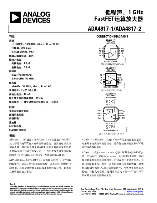
CONNECTION DIAGRAMS
ADA4817-1
TOP VIEW (Not to Scale) PD 1 FB 2 –IN 3 +IN 4 8 +VS 7 OUT 6 NC 5 –VS NC = NO CONNECT
07756-001
图1. 8引脚LFCSP (CP-8-2)
应用
光电二极管放大器 数据采集前端 仪器仪表 滤波器 ADC驱动器 CCD输出缓冲器
–IN1 1 +IN1 2 NC 3 –VS2 4
OUT2 5 +VS2 6 PD2 7 FB2 8
12 –VS1 11 NC 10 +IN2 9 –IN2
NC = NO CONNECT
概述
ADA4817-1(单通道)和 ADA4817-2(双通道) FastFET™ 放大器是具有FET输入的单位增益稳定、超高速电压反馈 型放大器。这些放大器采用 ADI公司的专有超快速互补双 极性(XFCB)工艺进行开发,这一工艺可使放大器实现超低 的噪声(4 nV/√Hz;2.5 fA/√Hz)及极高的输入阻抗。 ADA4817-1/ADA4871-2具有1.3 pF的输入电容、4 nV/√Hz 的低噪声、最大2 mV的低失调电压,以及1050 MHz的−3 dB带宽,非常适合数据采集前端及宽带跨导应用,如光电 二极管前置放大器等。
ADA4817-1
TOP VIEW (Not to Scale)
8 7 6 5
PD +VS OUT
07756-002
NC
NC = NO CONNECT
图2. 8引脚SOIC (RD-8-1)
ADA4817-2
伊顿 用于 22x58 毫米保险丝的 IEC 700V 100A 模块块 数据表

IEC 700V/100A modular blocks for 22x58 mm fusesCatalog symbols:• JM70100-_CR (fuse block)• JM70100-_MW_ (power distribution fuse block)Description:Eaton’s Bussmann™ series JM70100 products are available for 22x58 mm gG, aM and select high speed fuses as either a fuse block or power distribution fuse block that eliminates the need for a separate power distribution block.These new blocks have multiple features that increase versatility, reduce labor and enhance safety for any panel or electrical system design. Rated for applications up to 700 V and 100 amps, their modular design allows for assembly of multiple pole configurations at the point of use. These blocks can also be ordered as factory configured 2- and 3-pole versions.The versatile 35 mm DIN-rail or panel mount capability allows using the same block for multiple applications and reducing inventory cost. Optional IP20 finger-safe covers enhance electrical safety with a lockout/tagout feature and can be ordered with or without open fuse indication to speed troubleshooting.The patented power distribution fuse block configurations simplify your panel layout and require up to 78% less panel space. Additionally, they lower inventory cost while reducing installation time and labor by an average of 36%. Features and benefits:• Combination power distribution block and fuse block versions reduce wire connections and total panel components, requiring up to 78% less panel space and reducing installation time and labor by an average of 36%.• A 200kA withstand rating helps achieve a higher assembly short-circuit current rating (SCCR)for compliance with NEC® sections 110.10, 409.110(4), 409.22, 440.4(B), 670.3(A)(4) and 670.5.• Optional see-through cover enhances safety with IP20 finger-safe protection, lockout/tagout capability and open circuit indication.• Available in 1-, 2-, and 3-pole configurations to meet stocking requirements.• To reduce inventory, assembly time and labor, modular single-pole blocks snap-together for tool-less assembly of multiple poles at point of use.• DIN-rail and panel mount versatility allows one product to be used for multiple applications without incurring additional inventory cost.Fuses not included.2Technical Data 10496Effective June 2021IEC 700V/100A modular blocks for 22x58mm fuses/bussmannseriesSpecifications:Fuse class•IEC 22x58 mm gG, gL, aM and aR and gR high speed fusesRatings• Volts: 700 V • Amps: up to 100 A•Withstand: 200kA RMS SymAgency information:•Blocks• UL Recognized E14853 – IZLT2•CSA Component acceptance 47235 — 6225-01•Covers UL Listed UL E58836 – JDVSPoles•1-, 2-, 3-poleFlammability ratings• Blocks: UL 94V0, self-extinguishing •Covers: UL 94HB, self-extinguishingOperating and storage temperature range• Blocks: -40°C to +120°C•Covers:• Non-indicating -40°C to +120°C•Indicating -20°C to +90°CMaterials• Base: Thermoplastic•Terminals: Tin-plated aluminumConductors•75°C Cu/Al** Conductors with higher temperature rating may be used, but at their 75°C ampacity.Accessories:•Optional IP20 finger-safe covers in indicating and non-indicating versions. Order one for each pole.Recommended fuses (order separately)C22G_ IEC 22x58mm Class aM fuses up to 100720115FWP-_ 22x58mm high speed fusesup to 100*720026* Not for use with striker versions and must be applied within the operating temperature range of the block.Catalog numbers:3Technical Data 10496Effective June 2021IEC 700V/100A modular blocks for 22x58mm fuses /bussmannseries Dimensions - in (mm)CVRI-J-60060(WITH INDICATION)JM70100-3CR180.7JM70100-1CR JM70100-2CRIEC 700V/100A modular blocks for 22x58mm fusesTechnical Data 10496Effective June 2021Eaton and Bussmann are valuable trademarks of Eaton in the U.S. and other countries. Y ou are not permitted to use the Eaton trademarks without prior written consent of Eaton.Eaton1000 Eaton Boulevard Cleveland, OH Bussmann Division 114 Old State Road Ellisville, MO 63021United States/bussmannseries © 2021 EatonAll Rights Reserved Publication No. 10496June 2021Follow us on social media to get thelatest product and support information.For Eaton’s Bussmann series product information,call 1-855-287-7626 or visit:/bussmannseriesThe only controlled copy of this data sheet is the electronic read-only version located on the Eaton network drive. All other copies of this document are by definition uncontrolled. This bulletin is intended to clearly present comprehensive product data and provide technical information that will help the end user with design applications. Eaton reserves the right, without notice, to change design or construction of any products and to discontinue or limit distribution of any products. Eaton also reserves the right to change or update, without notice, any technical information contained in this bulletin. Once a product has been selected, it should be tested by the user in all possible applications.。
CS6R-380至405W全黑单极PV模块说明书

CS6R-380|385|390|395|400|405MS380 W ~ 405 WMORE POWERMORE RELIABLEComprehensive LID / LeTID mitigation technology, up to 50% lower degradationModule power up to 405 W Module efficiency up to 20.7 %405 WMinimizes micro-crack impactsBetter shading toleranceLower LCOE & system costIEC 61215 / IEC 61730 / CE / INMETRO / MCS / UKCAUL 61730 / IEC 61701 / IEC 62716 / IEC 63126 Level1 / IEC 60068-2-68 UNI 9177 Reaction to Fire: Class 1 / Take-e-way* For detailed information, please refer to the Installation Manual.Heavy snow load up to 5400 Pa, wind load up to 2400 Pa*HiKu6 (All-Black)CSI Solar Co., Ltd.199LushanRoad,SND,Suzhou,Jiangsu,China,215129,,********************ALL BLACK MONO PERCCSI Solar Co., Ltd. is committed to providing high quality solar photovoltaic modules, solar energy and battery storage solutions to customers. The company was recognized as the No. 1 module supplier for quality and performance/price ratio in the IHS Module Customer Insight Survey. Over the past 22 years, it has successfully delivered over 88 GW of premium-quality solar modules across the world.* The specific certificates applicable to different module types and markets will vary, and therefore not all of the certifications listed herein will simultaneously apply to the products you order or use. Please contact your local Canadian Solar sales representative to confirm the specific certificates available for your Product and applicable in the regions in which the products will be used.PRODUCT CERTIFICATES*MANAGEMENT SYSTEM CERTIFICATES*YearsYearsIndustry Leading Product Warranty on Materials and Workmanship*Linear Power Performance Warranty*1st year power degradation no more than 2%Subsequent annual power degradation no more than 0.55%*Subject to the terms and conditions contained in the applicable Canadian Solar Limited Warranty Statement. Also this 25-year limited product warranty is available only for prod -ucts installed and operating on residential rooftops in certain regions.ISO 9001 : 2015 / Quality management systemISO 14001 : 2015 / Standards for environmental management systemISO 45001 : 2018 / International standards for occupational health & safety IEC62941 : 2019 / Photovoltaic module manufacturing quality systemPARTNER SECTIONENGINEERING DRAWING (mm)Rear ViewCS6R-400MS / I-V CURVES* The specifications and key features contained in this datasheet may deviate slightly from our actual products due to the on-going innovation and product enhancement. CSI Solar Co., Ltd. reserves the right to make necessary adjustment to the information described herein at any time without further notice.Please be kindly advised that PV modules should be handled and installed by qualified people who have professional skills and please carefully read the safety and installation instructions before using our PV modules.CSI Solar Co., Ltd.199LushanRoad,SND,Suzhou,Jiangsu,China,215129,,********************VA V A1000 W/m 800 W/m 600 W/m400 W/m200 W/m5°C 25°C 45°C 65°CMECHANICAL DATASpecificationDataCell TypeMono-crystalline Cell Arrangement 108 [2 X (9 X 6) ]Dimensions1722 ˣ 1134 ˣ 30 mm (67.8 ˣ 44.6 ˣ 1.18 in)Weight21.3 kg (47.0 lbs)Front Cover 3.2 mm tempered glass with anti-reflective coatingFrame Anodized aluminium alloy, J-Box IP68, 3 bypass diodesCable4 mm 2 (IEC), 12 AWG (UL)ConnectorT6 or MC4 or MC4-EVO2 or MC4-EVO2ACable Length(Including Connector)Portrait: 350 mm (16.1 in) (+) / 250mm (11.4 in) (-); landscape: 1100mm (43.3 in)*Per Pallet 35 pieces Per Container (40' HQ)910 pieces* For detailed information, please contact your local Canadian Solar sales and technical representatives.141312111098765432105 10 15 20 25 30 35 40 45 50 55 60 5 10 15 20 25 30 35 40 45 50 55 600 ~ + 10 W1413121110987654321ELECTRICAL DATA | STC*CS6R380MS 385MS 390MS 395MS 400MS 405MS Nominal Max. Power (Pmax)380 W 385 W 390 W 395 W 400 W 405 W Opt. Operating Voltage (Vmp)30.0 V 30.2 V 30.4 V 30.6 V 30.8 V 31.0 V Opt. Operating Current (Imp)12.69 A 12.77 A 12.84 A 12.91 A 12.99 A 13.07 A Open Circuit Voltage (Voc)36.0 V 36.2 V 36.4 V 36.6 V 36.8 V 37.0 V Short Circuit Current (Isc)13.55 A 13.63 A 13.70 A 13.77 A 13.85 A 13.93 A Module Efficiency 19.5%19.7%20.0%20.2%20.5%20.7%Operating Temperature -40°C ~ +85°CMax. System Voltage 1500V (IEC/UL) or 1000V (IEC/UL)Module Fire Performance TYPE 1 (UL 61730 1500V) or TYPE 2 (UL 61730 1000V) or CLASS C (IEC 61730)Max. Series Fuse Rating 25 A Application Classification Class A Power Tolerance* Under Standard Test Conditions (STC) of irradiance of 1000 W/m 2, spectrum AM 1.5 and cell tempe -rature of 25°C.ELECTRICAL DATA | NMOT*CS6R380MS 385MS 390MS 395MS 400MS 405MS Nominal Max. Power (Pmax)284 W 288 W 291 W 295 W 299 W 303 W Opt. Operating Voltage (Vmp)28.1 V 28.3 V 28.4 V 28.6 V 28.8 V 29.0 V Opt. Operating Current (Imp)10.12 A 10.19 A 10.26 A 10.33 A 10.39 A 10.45 A Open Circuit Voltage (Voc)33.9 V 34.1 V34.2 V 34.4 V 34.6 V 34.7 V Short Circuit Current (Isc)10.91 A 10.98 A 11.05 A 11.11 A 11.17 A 11.23 A* Under Nominal Module Operating Temperature (NMOT), irradiance of 800 W/m 2, spectrum AM 1.5, ambient temperature 20°C, wind speed 1 m/s.TEMPERATURE CHARACTERISTICSSpecificationData Temperature Coefficient (Pmax)-0.34 % / °C Temperature Coefficient (Voc)-0.26 % / °C Temperature Coefficient (Isc)0.05 % / °CNominal Module Operating Temperature 42 ± 3°CMounting HoleFrame Cross Section A-AMar. 2023. All rights reserved, PV Module Product Datasheet V2.1C25_EN。
- 1、下载文档前请自行甄别文档内容的完整性,平台不提供额外的编辑、内容补充、找答案等附加服务。
- 2、"仅部分预览"的文档,不可在线预览部分如存在完整性等问题,可反馈申请退款(可完整预览的文档不适用该条件!)。
- 3、如文档侵犯您的权益,请联系客服反馈,我们会尽快为您处理(人工客服工作时间:9:00-18:30)。
Bosch Rexroth AG ,RC 30110,版本:2013-04目录特点 1订货代码 2功能2电路图/插脚分配,选件 T1 4电路图/插脚分配,选件 T5 5技术数据 6特性曲线7显示/调节元件,选件 T1 8显示/调节元件,选件 T5 9尺寸11项目规划/维护说明/附加信息11特点▶差分输入(±10 V)▶ 4 个可调用控制值输入(±10 V) ▶电流输入(4 … 20 mA)▶通过 24 V 输入或跳线改变内部控制值信号极性▶通过相位识别(24 V 输入)或斜坡时间调用(24 V 输入)选择斜坡时间(选件 T5) ▶通过跳线选择斜坡时间范围▶通过可分别调节的阶跃电平和最大值进行特性曲线校正 ▶选通输入 ▶"斜坡开/关"输入 ▶"准备就绪"输出信号▶可通断的测量插口(选项 T5) ▶电源反向极性保护▶电源带直流/直流转换器, 不改变零电位H7299用于比例方向阀和比例压力阀的阀放大器▶组件系列 2X ▶模拟,欧洲板卡格式 ▶适用于控制比例方向阀:– 4WRA 6…-2X,4WRA 10…-2X,– 4WRZ…-7X,以及比例压力阀:– 3DREP 6..2XRC 30110版本:2013-04替代对象:05.12型号 VT-VSPA2-1注意事项:使用 VT-VSPA2-1-2X 放大器板卡作为 VT 3000-3X,VT 3006-3X,VT 3013-3X,VT 3014-3X,VT 3017-3X,VT 3018-3X,VT 3026-3X,VT-VSPA2-1-1X/… 或VT-VSPA2-50-1X/… 的替代品时,确保遵守符合 30110-Z 附加信息的配置和设置信息。
2/12VT-VSPA2-1 | 阀放大器Bosch Rexroth AG ,RC 30110,版本:2013-04订货代码01用于比例方向阀和比例压力阀的阀放大器,模拟,欧洲板卡格式VT-VSPA202用于控制比例方向阀 4WRA 6…-2X,4WRA 10…-2X 和 4WRZ…-7X 以及比例压力阀 3DREP 6..2X 103组件系列 20 至 29(20 至 29:技术数据和插脚分配不变)2X 04型号:标准V005选项:对于一个斜坡时间T1选项:对于五个斜坡时间T506明文形式的更多详细信息*010203040506VT-VSPA2–1–2X /V0//*功能开放式板卡插槽 VT 3002-1-2X/48F(请参阅样本 29928)附件供电设备 [1]放大器板卡随附了带接通电流限制器的供电设备。
此设备提供了所有内部所需的正和负电源电压。
控制值规格通过差分输入 [2] 和电流输入 [3],启用信号 [4] 及零位偏移 [5](调零电位计 "Zw")中可用的外部控制值信号之和(总和 [6]),计算内部控制值信号。
下列内容适用:标准值电流输入差分输入控制值测量插口流动方向–100 % 4 mA –10 V –10 V P 至 B,A 至 T0 %12 mA 0 V 0 V 100 %20 mA 10 V10 V P 至 A,B 至 T 0 %< 1 mA 1)0 V1)如果电流输入未连接或在电流控制值的电缆断连情况下,产生的内部控制值信号将为 0 %。
电流和电压输入之间不进行切换。
输入始终可用(请参阅电路图)。
控制值启用 [4]可以选择四个控制值信号 "w1" 至 "w4"。
外部控制值电压(控制值 1 至 4)直接通过 +10 V 和 –10 V 调节电压输出或通过外部电位计进行定义。
如果这些控制值输入直接连接至调节电压,则使用电位计 "w1" 至 "w4" 设置控制值。
使用外部电位计时,内部电位计将用作衰减器或限制器。
在同一时刻,只能操作一个启用。
如果同时操作了几个启用,启用 "1" 优先权最低,启用 "4" 优先权最高。
各个处于活动状态的启用通过面板上的黄色 LED 指示。
控制值极性变化 [7]通过输入信号在内部产生的控制值,控制值启用和零电位偏移信号可通过外部信号或跳线 J1 改变极性。
极性变化情况通过面板上的 LED("–1")进行指示。
阀放大器 | VT-VSPA2-1 3/12RC 30110,版本:2013-04,Bosch Rexroth AG启用功能 [8]启用功能可启用功率输出级并将内部控制值信号前馈到斜坡发生器。
使能信号通过面板上的 LED 进行指示。
如果连接启用,则内部控制值(无论哪类控制值规格)会按所设置的斜坡时间发生变化。
这样,受控阀不会突然打开。
斜坡发生器 [9]斜坡发生器限制控制输出上升。
下游阶跃函数和振幅衰减器不会延长或缩短斜坡时间。
使用"斜坡开/关"信号或跳线 J2 将斜坡时间设置为最小值(< 2 ms) (斜坡关闭)。
外部斜坡时间设置:可使用外部电位计延长内部设置的斜坡时间。
此设置可通过测量插口进行验证。
如果电缆断连,则内部默认设置将自动有效。
设置和测量斜坡时间的注意事项:测量插口 "t"(T1)/ "v"(T5)处的值U t / V 532当前斜坡时间(±20 %)t / ms203350U t / V 10.50.30.20.10.050.030.02t / ms1002003335001000200033335000可通过闭合跳线 J3 使上述斜坡时间增加十倍。
特性曲线发生器 [10]使用可调节特性曲线发生器,正信号和负信号的阶跃电平和最大值可以根据液压要求单独设置。
穿过零电位的特性曲线的实际发展不是阶跃式的,而是线性的。
限幅器 [11]内部控制值被限制在约公称范围的 ±110 %。
时钟发生器 [13]时钟发生器会产生输出级的时钟频率。
可使用跳线将时钟信号转换成三个基本频率范围。
功率输出级 [16]功率输出级产生比例阀的定时线圈电流。
线圈电流被限制在每输出 2.5 A。
输出级输出具有防短路功能。
出现内部故障信号或未启用时,输出级将被断电。
故障识别 [17]监控输出级是否存在过电流。
[ ] = 对第 4 和 5 页上电路图的赋值4/12VT-VSPA2-1 | 阀放大器Bosch Rexroth AG ,RC 30110,版本:2013-04电路图/插脚分配,选件 T1控制值 4控制值 3控制值 2控制值 1外部斜坡时间控制值 5 ±10 V控制值 64…20 m A控制值选择 1 至 4极性变化启用工作电压斜坡开/关1 供电设备2 差分输入3 电流输入4 控制值选择逻辑5 零电位设置7控制值极性变化8启用功能9 斜坡函数发生器10 特性曲线发生器12 控制值输出13 时钟发生器14 实际电流值输出15 电流控制器16 功率输出级17 故障识别o k 1 输出级启用信号o k 2 板卡监控阀放大器 | VT-VSPA2-15/12RC 30110,版本:2013-04,Bosch Rexroth AG电路图/插脚分配,选件 T5控控控控外部斜坡控制±1控制4…20 控制值选择 1 极工作电压斜斜坡选择 1 4 相1供电设2 差分输3 电流输4 控制值选择逻辑5 零电位设置6 控制值总和10 特性曲线发生器11 限幅器12 控制值输出16 功率输出级17 故障识别18 测量点切换19 斜坡时间选择逻辑o k 1 输出级启用信号o k 2 板卡监控6/12VT-VSPA2-1 | 阀放大器Bosch Rexroth AG ,RC 30110,版本:2013-04技术数据(有关这些参数之外的应用,请务必向我们咨询!)工作电压U B 24 VDC + 40 % – 20 %工作范围:上限值U B (t)最大35 V 下限值U B (t)最小18 V功耗P S < 50 VA 电流消耗I < 2 A保险丝I S 2 A 中间时间延迟,可替换输入,模拟控制值 1 至 4(电位计输入)U e 0 … ±10 V,R e > 100 kΩ(M0 为基准)控制值 5(差分输入)U e 0 … ±10 V,R e > 50 kΩ控制值 6(电流输入)I e 4 … 20 mA,负载 R B = 100 Ω外部斜坡时间U e 0 … +10 V,R e = 10 kΩ(内部增加至 +15 V;M0 为基准)输入,数字控制值启用,控制值极性变化,启用,斜坡开/关,斜坡选择(选件 T5),4 相位操作(选件 T5)U U 8.5 V … U B –> ON,R e > 100 kΩ0 … 6.5 V –> OFF,R e > 100 kΩ设置范围零点调节(电位计 "Zw")±30 %控制值(电位计 "w1" 至 "w4")0 … 110 %斜坡时间(电位计 "t1" 至 "t5")20 ms … 5 s,可通断时为 0.2 … 50 s 阶跃电平(电位计 "S+" 和 "S–")0 … 50 %振幅衰减器(电位计 "G+" 和 "G–")0 ... 110 %(适用于 0 % 的阶跃电平设置)输出内部控制值U ±10 V ± 2 %,I 最大 = 2 mA实际电流值U ±2.5 V ± 2 %,I 最大 = 2 mA(mV ≙ mA)测量信号(选件 5)U ±10 V ± 2 %,I 最大 = 2 mA准备就绪U > 16 V,50 mA(发生故障时:U < 1 V,R i = 10 kΩ)调节电压U ±10 V ± 2 %,25 mA,防短路功率输出级I 0 … 2.5 A,防短路测量插口控制值 "w"±10 V ± 2 %,I 最大 = 2 mA实际电流值信号 "I"±2.5 V ± 2 %,I 最大 = 2 mA(mV ≙ mA)斜坡时间 "t"请参阅第 3 页的说明插口 "v"(选件 T5)请参阅第 3 页的说明和第 10 页上的表格时钟频率WRA6…2X f 300 … 370 Hz(U B = 24 V 并且 U 控制 = 0 V: 370 Hz 时)WRA10…2X f 180 … 410 Hz(U B = 24 V 并且 U 控制 = 0 V: 410 Hz 时)WRZ…7X f 170 Hz 3DREP 6…2X f 170 Hz连接类型48 针多点插头,DIN 41612,设计 F 板卡尺寸欧洲板卡 100 x 160 mm,DIN 41494允许的工作温度范围ϑ0 … 50 °C 存储温度范围ϑ–25 °C … +85 °C 重量m 0.17 kg(净重)注意事项:有关在 EMC(电磁兼容性),气候和机械负载领域中进行的环境模拟测试的信息,请参阅样本 30110-U。