
3R3-大电流电感
Applications•Voltage Regulator Module (VRM)•Multi-phase regulators •Point-of-load modules•Desktop and server VRMs and EVRDs •Base station equipment •Notebook regulators •Battery power systems •Graphics cards•Data networking and storage systemsEnvironmental Data•Storage temperature range:-55°C to +125 °C •Operating temperature range:-55°C to +125°C (ambient plus self-temperature rise)•Solder reflow temperature:J-STD-020D compliantPackaging•Supplied in tape and reel packaging,1,500 parts per 13”diameter reelDescription•Halogen Free•125°C maximum total temperature operation•7.4 x 7.0 x 3.0mm maximum surface mount package •Powder iron core material •Magnetically shielded,low EMI•High current carrying capacity,Low core losses •Inductance range from 0.15μH to 10.0μH •Current range from 3.2 to 52 Amps •RoHS compliantHigh Current,Power InductorsHCM0703 SeriesSMD Device1Open Circuit Inductance (OCL) Test Parameters:100kHz,0.25V rms ,0.0Adc,@ +20°C.2Full Load Inductance (FLL) Test Parameters:100kHz,0.25V rms ,I sat @ +20°C.3I rms :DC current for an approximate temperature rise of 40°C without core loss.Derating is necessary for AC currents.PCB layout,trace thickness and width,air-flow and proximity of other heat generating components will affect the temperature rise.It is recommended that thetemperature of the part not exceed 125°C under worst case operating conditions verified in the end application.4I sat :Peak current for approximately 20% rolloff at +20°C.5K-factor:Used to determine B p-p for core loss (see graph).B p-p = K *L *ΔI.B p-p (Gauss),K:(K-factor from table),L:(inductance in μH),ΔI (peak-to-peak ripple current in amps).6Part Number Definition:HCM0703-xxx-R • HCM0703 = Product code and size• xxx= Inductance value in μH,R = decimal point,If no R is present then 3rd digit equals number of zeros.• “-R”suffix = RoHS compliantProduct SpecificationsPartOCL 1(μH)FLL min,2I rms 3I sat 4 @ 20°C DCR (m Ω) @ 20°C DCR (m Ω) @ 20°CNumber 6±20%(μH)(Amps)(Amps)(Typical)(Maximum)K-factor 5HCM0703-R15-R 0.150.0926.052.0 1.90 2.501610.3HCM0703-R22-R 0.220.1323.040.0 2.50 2.80615.4HCM0703-R47-R 0.470.2817.526.0 4.00 4.20430.2HCM0703-R68-R 0.680.4115.525.0 5.00 5.50367.4HCM0703-R82-R 0.820.4913.024.0 6.708.00286.2HCM0703-1R0-R 1.000.6011.022.09.0010.0259.7HCM0703-1R5-R 1.500.909.0018.014.015.0175.7HCM0703-2R2-R 2.20 1.328.0014.018.020.0163.6HCM0703-3R3-R 3.30 1.98 6.0013.528.030.0158.2HCM0703-4R7-R 4.70 2.82 5.5010.037.040.0118.1HCM0703-6R8-R 6.80 4.08 4.508.0054.060.0106.8HCM0703-8R2-R 8.20 4.92 4.007.5064.068.095.3HCM0703-100-R10.06.003.207.0070.577.681.2D i m e n s i o n s-m mTemperature Rise vs.Total LossThe only controlled copy of this Data Sheet is the electronic read-only version located on the Cooper Bussmann Network Drive. All other copies of this document are by definition uncon-trolled. This bulletin is intended to clearly present comprehensive product data and provide technical information that will help the end user with design applications. Cooper Bussmann reserves the right, without notice, to change design or construction of any products and to discontinue or limit distribution of any products. Cooper Bussmann also reserves the right to change or update, without notice, any technical information contained in this bulletin. Once a product has been selected, it should be tested by the user in all possible applications.Life Support Policy: Cooper Bussmann does not authorize the use of any of its products for use in life support devices or systems without the express written approval of an officer of the Company. Life support systems are devices which support or sustain life, and whose failure to perform, when properly used in accordance with instructions for use provided in the label-ing, can be reasonably expected to result in significant injury to the user.North AmericaCooper Electronic Technologies 1225 Broken Sound Parkway NW Suite FBoca Raton, FL 33487-3533Tel: 1-561-998-4100Fax: 1-561-241-6640Toll Free: 1-888-414-2645Cooper Bussmann P .O. Box 14460St. Louis, MO 63178-4460Tel: 1-636-394-2877Fax: 1-636-527-1607EuropeCooper Electronic Technologies Cooper (UK) Limited Burton-on-the-WoldsLeicestershire • LE12 5TH UK Tel: +44 (0) 1509 882 737Fax: +44 (0) 1509 882 786Cooper Electronic Technologies Avda. Santa Eulalia, 29008223Terrassa, (Barcelona), Spain Tel: +34 937 362 812+34 937 362 813Fax: +34 937 362 719Asia PacificCooper Electronic Technologies 1 Jalan Kilang Timor#06-01 Pacific Tech Centre Singapore 159303Tel: +65 278 6151Fax: +65 270 4160Solder Reflow Profile。
顺络WPN系列大电流小尺寸功率电感器,合金粉磁芯,完美应对手机超薄大电流需求
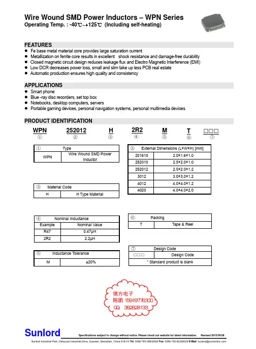
Part Number
Units Symbol WPN201610MR24MT WPN201610MR33MT WPN201610MR47MT WPN201610MR68MT WPN201610M1R0MT WPN201610M2R2MT
WPN201610U Series
Inductance
@1MHz μH L
0.33±20% 0.47±20% 0.68±20% 1.0±20% 1.5±20% 2.2±20%
Inductance
@1MHz μH L
0.33±20% 0.47±20% 0.68±20% 1.0±20% 1.5±20% 2.2±20%
DC Resistance
Max. Typ. Ω
DCR 0.040 0.033 0.049 0.041 0.065 0.057 0.090 0.075 0.070 0.060 0.130 0.110 0.170 0.142 0.425 0.370 0.826 0.688
DC Resistance
Max. Typ. Ω
DCR 0.026 0.022 0.038 0.032 0.044 0.037 0.060 0.050 0.090 0.075 0.160 0.135
E 0.6±0.2 0.6±0.2 0.6±0.2 0.8±0.2 0.8±0.2 0.75±0.2 0.95±0.2 0.95±0.2
F 0.8±0.2 0.8±0.2 0.8±0.2 0.8±0.2 0.8±0.2 1.5±0.2 2.1±0.2 2.1±0.2
a Typ. 0.7 0.7 0.7 0.8 0.8 1.5 1.9 1.9
QQ:382828133
以太网接口电路、POE接口电路设计.

4.
POE简介
• • • • • PD必须对电压极性不敏感,并且能在备用线对和数据线对上正常工作(提供检测和分级 特征以及接受供电),这个自动极性电路通常用二极管桥堆(或二极桥式整流电路)来 实现 以太网75Ω 共模终端电阻必须 AC 耦合,这样才能不干扰PSE对PD的检测、分类和供电 PSE供电电压为44~57V,典型值为48V。在正常情况下最大输出电流为350mA。输出连续 功率大约为15.4W PD正常受电电压为37~57V。平均输入功率为12.95W,输入峰值电流为400mA。典型工作 电流为10~350mA,超载检测电流为350~500mA 对于PSE,馈送电源可以是RJ45的1-2/3-6线对,也可以是4-5/7-8线对,而且只能选用 其中一对;对于PD,要求两线对都能吸收电源
主要内容
• 以太网接口电路 • POE接口电路设计
以太网接口的标准定义
• 以太网设备满足正常通信,IEEE802.3对RJ45端口信号有规定,要求电脑与HUB用直通线连 接能正常通信,则要求电脑的网卡NIC的TX、RX分别连接到HUB的RX、TX,所以,它们的 RJ45接口的PIN脚定义是不一样的,具体如下: 网卡NIC对RJ45接口PIN脚定义: RJ45 PIN: 1 2 3 4 5 6 7 8 信号定义: TX+ TX- RX+ NA NA RX- NA NA HUB对RJ45接口PIN脚定义: RJ45 PIN: 1 2 3 4 5 6 7 8 信号定义: RX+ RX- TX+ NA NA TX- NA NA • 随着以太网技术的不断发展,出现了新类型的产品,对以下产品进行分类: 1. 与NIC同类型的有:HUB和交换机上联口,Router、Gateway、IPphone等设备的WAN口,称 为“MDI口” 2. 与HUB同类型的有:HUB和交换机下联口,Router、Gateway、IPphone、XDSL等设备的LAN 口,称为“MDIX口” 3. “MDI口”与“MDIX口”被称为两种不同类型设备端口,它们之间被指定用直通线连接, 而同类型设备端口之间用交叉线连接。如果芯片支持AUTO MDII-X功能的端口,可以用交 叉线或直通线连接任何类型的端口
直流电阻测量

直流电阻测量9.熟悉直流电阻测试的目的、测试方法和测试时的注意事项。
一、测量直流电阻的意义有些电气设备具有线圈等导电回路,例如发电机、电动机、变压器等。
这些线圈的导线都包有绝缘,在制造过程中可能存在质量问题。
例如导线连接接头焊接不良,或者存在匝间短路,也可能线圈的引出线与接线端子的连接拧得不紧。
如果存在这些缺陷,电气设备投入运行时,可能很快发生事故;也可能在运行一段时间后,由于过负荷等原因,产生局部过热,最终导致设备事故。
测量这些设备导电回路的直流电阻,就是为了及时发现线圈等导电回路的隐患,防止不合格的设备投入运行。
此外,断路器等开关设备的触头闭合不严,或者引接线的接触不良,在长期通过大电流时由于接触电阻过大而局部过热,最后导体熔化造成事故。
对这些设备导电回路测量直流电阻就是为了校验开关触头是否接触良好,引接线的连接是否紧固,防止运行中接触点产生过热引起事故。
二、直流电阻测试方法1.直流压降法电流、电压表法又称直流压降法,其原理是在被测电路中通以直流电流,测量两端压降,根据欧姆定律计算出被测电阻。
图3-16为直流压降法测量直流电阻原理接线图。
图中R某为被测电阻,I为测量电流,U为测量电压。
根据欧姆定律R某=U/I。
由于电流表和电压表都存在内阻,对测量结果会造成影响,引起误差。
因此在计算电阻时,应把电流表和电压表的内阻考虑进去。
设电流表的内阻为rA,电压表的内阻为rv。
(1)采用图3-16(a)所示接线方式时R某U(3-19)UIrV式中R某——被测直流电阻,Ω;U——电压表指示的电压,V;I——电流表指示的电流,A;rV——电压表的内电阻,Ω。
(2)采用图3-16(b)所示接线方式时R某UIrA(3-20)I式中rA——电流表的内电阻,Ω。
图3-16(a)所示测量方法中,电流表中流过的电流包括两部分,其中主要部分是流过被测电阻R某的电流,另有一很小的电流是流过电压表的电流。
对于同一块电压表,电源电压不变,流过的电流也不变。
CMP大电流贴片电感(叠层功率电感)规格书

16
【 南京南山半导体有限公司 — 风华高科叠层贴片电感选型资料】
FERRITE CHIP INDUCTORS
ELECTRICAL CHARACTERISTICS
2520 TYPE
Part No. CMP252009UD1R0 K/M/N CMP252009UD1R2 K/M/N CMP252009UD1R5 K/M/N CMP252009UD1R8 K/M/N CMP252009UD2R2 K/M/N CMP252009UD2R7 K/M/N CMP252009UD3R3 K/M/N CMP252009UD3R9 K/M/N CMP252009UD4R7 K/M/N Pnductance ( H) 1.0 1.2 1.2 1.8 2.2 2.7 3.3 3.9 4.7 1 Test Fre. (MHz) SRF (MHz)Min 70 50 50 40 40 30 30 25 25 DCR ( )Max Ir (mA)Max 1500 1500 1500 1000 1000 1000 1000 1000 1000
APPLICATIONS
VCD/DVD VCD/DVD digital cameras personal computers etc.
ORDERING CODE
CMP 201209 V D 47N K T
(L Product Code (mm)
W T) Material Code U V J X Series Code
0.01 0.01 0.06 0.06 0.06 0.06 0.06 0.06 0.06 0.06 0.06 0.09 0.09 0.10 0.10 0.10 0.15 0.15 0.17 0.24 0.24 0.30 0.30 0.38 0.38 0.45 0.45 0.55 0.55 0.55 0.65 0.65 0.85 0.85
《天津大学电路2007-2012年考研真题及答案解析》

4
8
端电压
入端阻抗 Zin; 端电压 ;
(3)终端短路电流 。
《天津大学电路历年考研真题及答案解析》
4/113
天津大学2008年招收攻读硕士学位研究生入学考试试题
科目代码及名称:811 电路 答题说明:所有答案必须写在答题纸上,并写清楚题号,写在试题上无效。
目录
Ⅰ 历年考研真题试卷................................................................................................................. 2
天津大学 2007 年招收攻读硕士学位研究生入学考试试题...................................................2 天津大学 2008 年招收攻读硕士学位研究生入学考试试题...................................................5 天津大学 2009 年招收攻读硕士学位研究生入学考试试题...................................................8 天津大学 2010 年招收攻读硕士学位研究生入学考试试题.................................................11 天津大学 2011 年招收攻读硕士学位研究生入学考试试题.................................................15 天津大学 2012 年招收攻读硕士学位研究生入学考试试题................................................ 19
《电工电子技术与技能》(文春帆主编)习题参考答案

第一章 直流电路 复习与考工模拟参考答案一、填空题1.12 V 、24 V 、36 V 2.5 W 3.2.178×108 J 4.并联 5.12 K Ω 二、选择题 1.D2.A3.D4.D5.C三、判断题1.× 2.× 3.× 4.√ 5.√ 四、分析与计算题1.0.01 A ;10 mA ;1.0×10⁴ μA 2.(1)A 115(或0.45 A )(2)5.6 KW •h (3)2.8元第二章 电容与电感 复习与考工模拟参考答案一、填空题 1.106;1012 2.耐压3.储能;磁场;电场 4.103;1065.电阻(或欧姆) 二、选择题 1.D2.A3.C4.B5.A三、判断题1.√2.×3.×4.√5.√四、简答题略第三章磁场及电磁感应复习与考工模拟参考答案一、填空题1.安培定则(或右手螺旋定则)2.安培;BIlF=3.软磁物质;硬磁物质;矩磁物质4.电磁感应现象5.楞次二、选择题1.B 2.A 3.C 4.A 5.B三、判断题1.√2.√3.√4.×5.×四、分析与作图题1.略2.电流方向:BADCB第四章单相正弦交流电复习与考工模拟参考答案一、填空题1.振幅(最大值或有效值);频率(周期或角频率);初相2.V220(或311 V);s2.0;rad/s)02(或314πrad/s1003.有效值4.电压与电流同频同相;电压超前电流900;电流超前电压9005.正比;反比6.在电感性负载两端并联一容量适当的电容器二、选择题1.B 2.B 3.B 4.D 5.C三、判断题1.×2.√3.×4.×5.√ 6. ×7. ×四、分析与计算题1.最大值:10 A;有效值:A5;周期:0.2 s;频率:5 Hz;初相:150022.440 W3.(1)R=6Ω;L=25.5 mH (2)0.6第五章三相正弦交流电复习与考工模拟参考答案一、填空题1.线电压;相电压;相电压;线电压2.220 V;380 V3.3;等于4.使不对称负载获得对称的相电压5.3;等于二、选择题1.D2.C3.A4.B5. A三、判断题1.√2.√3.√4.√5.×四、分析与作图题1.星形和三角形两种;画图略2.星形联结承受220V相电压;三角形联结时则承受380V线电压。
3R3-大电流电感
Applications•Voltage Regulator Module (VRM)•Multi-phase regulators •Point-of-load modules•Desktop and server VRMs and EVRDs •Base station equipment •Notebook regulators •Battery power systems •Graphics cards•Data networking and storage systemsEnvironmental Data•Storage temperature range:-55°C to +125 °C •Operating temperature range:-55°C to +125°C (ambient plus self-temperature rise)•Solder reflow temperature:J-STD-020D compliantPackaging•Supplied in tape and reel packaging,1,500 parts per 13”diameter reelDescription•Halogen Free•125°C maximum total temperature operation•7.4 x 7.0 x 3.0mm maximum surface mount package •Powder iron core material •Magnetically shielded,low EMI•High current carrying capacity,Low core losses •Inductance range from 0.15μH to 10.0μH •Current range from 3.2 to 52 Amps •RoHS compliantHigh Current,Power InductorsHCM0703 SeriesSMD Device1Open Circuit Inductance (OCL) Test Parameters:100kHz,0.25V rms ,0.0Adc,@ +20°C.2Full Load Inductance (FLL) Test Parameters:100kHz,0.25V rms ,I sat @ +20°C.3I rms :DC current for an approximate temperature rise of 40°C without core loss.Derating is necessary for AC currents.PCB layout,trace thickness and width,air-flow and proximity of other heat generating components will affect the temperature rise.It is recommended that thetemperature of the part not exceed 125°C under worst case operating conditions verified in the end application.4I sat :Peak current for approximately 20% rolloff at +20°C.5K-factor:Used to determine B p-p for core loss (see graph).B p-p = K *L *ΔI.B p-p (Gauss),K:(K-factor from table),L:(inductance in μH),ΔI (peak-to-peak ripple current in amps).6Part Number Definition:HCM0703-xxx-R • HCM0703 = Product code and size• xxx= Inductance value in μH,R = decimal point,If no R is present then 3rd digit equals number of zeros.• “-R”suffix = RoHS compliantProduct SpecificationsPartOCL 1(μH)FLL min,2I rms 3I sat 4 @ 20°C DCR (m Ω) @ 20°C DCR (m Ω) @ 20°CNumber 6±20%(μH)(Amps)(Amps)(Typical)(Maximum)K-factor 5HCM0703-R15-R 0.150.0926.052.0 1.90 2.501610.3HCM0703-R22-R 0.220.1323.040.0 2.50 2.80615.4HCM0703-R47-R 0.470.2817.526.0 4.00 4.20430.2HCM0703-R68-R 0.680.4115.525.0 5.00 5.50367.4HCM0703-R82-R 0.820.4913.024.0 6.708.00286.2HCM0703-1R0-R 1.000.6011.022.09.0010.0259.7HCM0703-1R5-R 1.500.909.0018.014.015.0175.7HCM0703-2R2-R 2.20 1.328.0014.018.020.0163.6HCM0703-3R3-R 3.30 1.98 6.0013.528.030.0158.2HCM0703-4R7-R 4.70 2.82 5.5010.037.040.0118.1HCM0703-6R8-R 6.80 4.08 4.508.0054.060.0106.8HCM0703-8R2-R 8.20 4.92 4.007.5064.068.095.3HCM0703-100-R10.06.003.207.0070.577.681.2D i m e n s i o n s-m mTemperature Rise vs.Total LossThe only controlled copy of this Data Sheet is the electronic read-only version located on the Cooper Bussmann Network Drive. All other copies of this document are by definition uncon-trolled. This bulletin is intended to clearly present comprehensive product data and provide technical information that will help the end user with design applications. Cooper Bussmann reserves the right, without notice, to change design or construction of any products and to discontinue or limit distribution of any products. Cooper Bussmann also reserves the right to change or update, without notice, any technical information contained in this bulletin. Once a product has been selected, it should be tested by the user in all possible applications.Life Support Policy: Cooper Bussmann does not authorize the use of any of its products for use in life support devices or systems without the express written approval of an officer of the Company. Life support systems are devices which support or sustain life, and whose failure to perform, when properly used in accordance with instructions for use provided in the label-ing, can be reasonably expected to result in significant injury to the user.North AmericaCooper Electronic Technologies 1225 Broken Sound Parkway NW Suite FBoca Raton, FL 33487-3533Tel: 1-561-998-4100Fax: 1-561-241-6640Toll Free: 1-888-414-2645Cooper Bussmann P .O. Box 14460St. Louis, MO 63178-4460Tel: 1-636-394-2877Fax: 1-636-527-1607EuropeCooper Electronic Technologies Cooper (UK) Limited Burton-on-the-WoldsLeicestershire • LE12 5TH UK Tel: +44 (0) 1509 882 737Fax: +44 (0) 1509 882 786Cooper Electronic Technologies Avda. Santa Eulalia, 29008223Terrassa, (Barcelona), Spain Tel: +34 937 362 812+34 937 362 813Fax: +34 937 362 719Asia PacificCooper Electronic Technologies 1 Jalan Kilang Timor#06-01 Pacific Tech Centre Singapore 159303Tel: +65 278 6151Fax: +65 270 4160Solder Reflow Profile。
PAC03I 三相 SSR 电力调整器产品 说明书
智能交流电力控制器是中日合作超大功率固态继电器应用技术的新概念产品。
它包括三相调压/调功一体化PAC03I、工业DCS周波过零控制器ZAC10及后续系列。
额定电流40~500A,带锁相环同步电路、自动判别相位、缺相保护、上电缓启动、缓关断、散热器超温、快熔检测、电流限制、电压反馈、过流保护、串行工作状态指示、串行遥控操作器、PAC03IA还能与上位机通信,实现系统集成。
智能交流电力控制器可广泛用于工业各领域的电压调节,恒压,恒流,恒功率调节,适用于电阻性负载、电感性负载、变压器和电机软起控制等。
一. PAC03I主要技术指标:4~20mA输入: 接收阻抗120Ω 调节输出分辨力:0.2°,三相触发不平衡度:不大于0.6°负载方式: PAC03I 50Hz 三相380VAC 三角形或星形中心不接地。
移相范围:0~150°50Hz 三相380VAC 星形中心接地(220V负载) 移相范围:0~175°50Hz 三相380VAC 半控整流桥。
移相范围:0~175°隔离驱动输出:8V峰值脉冲,8°~ 120°可变脉宽,每路可2串2并接4支同相SSR。
最大驱动电流:< 30 mA纯阻电流等级:60A、90A、120A、180A、250A、300A 散热单元:B160、B227、B301A、B361、B401配置见选型表五只LED灯状态显示:红绿黄LED三相电源指示和快熔断路指示;绿色INPUT输入信号线性指示灯。
三色状态灯: RUN绿色运行灯;ALM红色报警灯;STOP黄色闪烁的待机灯。
外部执行开关的缓起动,缓关断: 无电压接点输入 闭合(ON):缓关断,时间固定3秒;开路(OFF): 由内部电位器P3设定0.2~120秒缓起动时间 不接:直接运行运行过程中自动缓起动及急停: 运行过程中瞬间缺相急停,加电后自动缓起动(三缺一相方式时被取消)。
(完整精品)大学物理实验报告之万用表的使用
大学物理实验报告学院班级实验日期 2017 年6 月6 日实验地点:实验楼B413室池等组成的,其作用是使表头适用于不同的测量项目和不同的测量范围。
对于不同的测量项目,测量线路的结构是不同的。
(1)直流电流挡其表头本身就是一个测量范围很小的直流电流表。
根据分流原理,表头与电阻并联就可增大测量范围,若表头与不同阻值的电阻并联,就可得到不同的量程。
并联电阻越小,量程也就越大。
图1是多量程直流电流挡原理图。
(2)直流电压挡表头本身也是一个量程很小的直流电压表,其量程为V g=I g R g(I g为表头满偏电流,R g为表头内阻)。
根据分压原理,表头与不同的电阻串联就能得到不同的量程。
图2是多量程电压表原理图。
(3)交流电压挡磁电式表头内永久磁体的磁场方向恒定,当通过交流电时,作用在可动部件上的力矩方向将随电流方向的变化而变化。
由于表头可动部分惯性较大,它在某一方向力矩作用下,还来不及转动,力矩的方向又发生了变化,这样,表头的指针实际上不可能转动。
所以,必须把交流电转换成直流电,才能测量。
图3是多量程交流电压表原理图,图中D1、D2为整流元件。
(4)电阻挡图4是欧姆表的原理图,它由表头、电池、电阻R i和调零电阻R0组成。
在a、b两端即红、黑两表棒之间可接入待测电阻R x。
测量前,先把两表棒短路即R x=0。
调节调零电阻R0使表头指针指到刻度线右端的满刻度,即欧姆表的零点。
此时,电路中的电流(式1)式中R z=R g+R0+R i+r称为欧姆表的综合电阻。
这一步骤称为欧姆表的调零。
测量未知电阻R x时,将它接入两表棒之间,则电路中的电流为:(式2)从上式可见,当ε和R Z恒定时,I仅随R x而变。
它们之间有一一对应的关系。
如果在刻度线上不同位置刻出相应的电阻值,那么在测量未知电阻时就可以在刻度线上直接读出被测电阻的数值。
从式2还可以看出,R x越大、I越小,表头指针偏转的角度越小,刻度的间隔也越小。
当R x→∞,即a、b间开路,I→0,指针在刻度线左端位置不动,所以刻度线左端的欧姆刻度为∞。
(整理)电阻,电容,电感,二极管,三极管,在电路中的作用
电阻,电容,电感,二极管,三极管,在电路中的作用电阻定义:导体对电流的阻碍作用就叫导体的电阻。
电阻(Resistor)是所有电子电路中使用最多的元件。
电阻的主要物理特征是变电能为热能,也可说它是一个耗能元件,电流经过它就产生热能。
电阻在电路中通常起分压分流的作用,对信号来说,交流与直流信号都可以通过电阻。
电阻都有一定的阻值,它代表这个电阻对电流流动阻挡力的大小。
电阻的单位是欧姆,用符号“Ω”表示。
欧姆是这样定义的:当在一个电阻器的两端加上1伏特的电压时,如果在这个电阻器中有1安培的电流通过,则这个电阻器的阻值为1欧姆。
出了欧姆外,电阻的单位还有千欧(KΩ,兆欧(MΩ)等。
电阻器的电气性能指标通常有标称阻值,误差与额定功率等。
它与其它元件一起构成一些功能电路,如RC电路等。
电阻是一个线性元件。
说它是线性元件,是因为通过实验发现,在一定条件下,流经一个电阻的电流与电阻两端的电压成正比——即它是符合欧姆定律:I=U/R常见的碳膜电阻或金属膜电阻器在温度恒定,且电压和电流值限制在额定条件之内时,可用线性电阻器来模拟。
如果电压或电流值超过规定值,电阻器将因过热而不遵从欧姆定律,甚至还会被烧毁。
线性电阻的工作电压与电流的关系如图1所示。
电阻的种类很多,通常分为碳膜电阻,金属电阻,线绕电阻等:它又包含固定电阻与可变电阻,光敏电阻,压敏电阻,热敏电阻等。
但不管电阻是什么种类,它都有一个基本的表示字母“R”。
电阻的单位用欧姆(Ω)表示。
它包括?Ω(欧姆),KΩ(千欧),MΩ(兆欧)。
其换算关系为:1MΩ=1000KΩ ,1KΩ=1000Ω。
电阻的阻值标法通常有色环法,数字法。
色环法在一般的的电阻上比较常见。
由于手机电路中的电阻一般比较小,很少被标上阻值,即使有,一般也采用数字法,即:101——表示100Ω的电阻;102——表示1KΩ的电阻;103——表示10KΩ的电阻;104——表示100KΩ的电阻;105——表示1MΩ的电阻;106——表示10MΩ的电阻。