S泵安装说明书介绍
苏尔寿泵说明书中文
2.8 不允许的运行方式
3.运输和贮存
3.1 运输和起吊
3.2 保存和贮存
4.描述
4.1 泵的描述
4.2 轴承和润滑
4.3 平衡轴向力-平衡鼓
5.泵的安装
5.1 安装
5.2 联轴器的安装
5.3 吸入和排出管路
5.4 辅助设备
最小流量装置
6.操作
6.1 概述
6.2 试车
6.3 开车和运转
6.4 禁止的运转方式
4
安装使用说明书
Ver 1.0
MC
- 所有工作完成以后,必须重新安装保护装置,使得每个保护装置重新使用。 - 在重新启动时应注意最初试车时的注意事项。 2.7 未经授权禁止测量和改造 未经过制造厂家同意,禁止对机械设备进行测量和改造,原始备件和辅助设备由生产厂 家授权提供,有安全质量保证。若使用其它厂家生产的备件,所产生的后果生产厂家不 承担任何责任。 2.8 不允许的运行方式 - 只有按照操作手册 1.4 段要求的数据合理的使用,才对提供的机械具有运行安全使用保
起吊 起吊重物的装置或绳索的检查
必须经过允许、确定无危险的绳索才可使用。承载的重物的质量必须适合起吊的装 置或绳索所能承受的重量。提供货物的总重量在安装图上给出,有的在交工资料上给 出。
不要站在悬挂重物的下面
包装箱绳索固定位置: 封闭包装箱绳索的固定位置要标示出来,包装箱里的货物 重心确定不下来,则绳索固定位置按照标示的位置固定
6.5 停车
6.6 重新启动程序
6.7 使用控制
6.8 运行故障
7.维护和检查
7.1 维护
泵
7.2
轴封
7.3
轴承润滑
7.4 检查
连成 S系列水泵说明书
CONTENTS01010202050812030718S Type pump figure dimension drawingS Type pump figure dimension table19S Type double-suction centrifugal pump installation dimension drawing(with foundation)23S Type pump with y type motor installation dimension drawing(with foundation)24S Type double-suction centrifugal pump installation dimension drawing(without foundation)26S Type pump spare parts table3801ABOUT THESTRUCTURES SERIES SINGLE-STAGE DOUBLE-SUCTION HORIZONTAL SPLIT CENTRIFUGAL PUMPBoth pump casing and cover form the worki ng chamber of the impeller and there are threaded holes for mounting vacuum and pressure meters on the flanges at both inlet and outlet and for water draining on the lower side of them.The impeller is static-balance calibrated, fixed with the m-uff and the muff nuts in both sides and its axial position can be adjusted via the nuts and axial force gets balanced by means of the symmetrical arrangement of its blades, there may be residual axial force which is borne by the bearing at the axle end.The pump shaft is supported by two single-column centripe-tal ball bearings, which are mounted inside of the bearing body on both ends of the pump and lubricated with grease. The dual-suction seal ring is used to reduce the leak at the impeller.Both inlet and outlet of this pump are placed under the axial line, horizontally and vertical to the axial line, the pump casing is opened in the middle so it is unneccessary to remove the water inlet and outlet pipelines and motor(or other prime movers). The pump moves CW viewing from the clutch to it. The pump moving CCW can also be made, but it should be specially noted at order. The main parts of the pump are: pump casing(1), pump cover (2), impeller (3), shaft(4), dual-suction seal ring(5), muff(6), be-aring(15) etc.and all of them, except the axle which is made of quality carbon steel, are made of cast iron. The material may be replaced with others upon different media.So 80CModel S pump is a single-stage double-suction horizontal split centrifugal pump and used to transport pure water and the liquid of both physical and chemical nature similar to those of water, the maximum temperature of which must not be over 80,suitable for water supply and drainage in factories, mines, cities and electric stations, waterlogged land drainage and irrigation of farming land and carious hydraulic projects.Pump's inlet diameter:150mm()(1)(2)(3)(4)(5)(6)(15)1Check both pump and motor to see if any damages with th- em.2The installat ion height f the pump plus the hydraulic lossof the suck-in pipeline and its speed energy is just the NPSHa of the unit, which should bigger than NPSHr. The dimensions of the basis should be in line with those of in- stallation of the pump unit.3. Installation sequences:The pump is driven directly by means of connecting to it via an elastic clutch. (Set up a stand additionally in case of a rubber band driving).The shaft seal is packing seal and, to cool and lubricate the seal cavity and prevent air from getting into the pump, there is a packing ring between the packing. A small volume of high-pressure water flows into the packing cavity via the tapered beard during the pump's working to act as a water seal.121. Assembly of the rotor's parts: in turn mount the impeller, muff, muff nut, packing sleeve, packing ring, packing gland, mechanical seal, mechanical seal bland, water retai ning r- i ng and bearing on the pump shaft, put on the dual-suction seal ring and then the clutch.2. Check the outer circles of the impeller's seal and the muff on the rotor separately, the radial jumping of which should not be over the settings in the table below.34()3Mount the rotor on the pump casing and adjust the impeller to have its axial position in the middle of the dual-suction seal ring in both sides and then fixed, then fix the gland of the b- earing's body with the fixing screws.4Put on the packing(in case of a packing seal), the paper pad on the middle opened face and the pump cover and tighten the threaded-tail conical pin first and then cover's nut. Mo- unt the packing gland, but do not press the packing too tig- htly, otherwise the muff may get heated to leave a bigger power consumption; while not too loose, or a big leak of liquid and reduced pump efficiency may re sult in. If me-chani cal seal is used, adjust the stud on the gland to ensure no leak with it.After a sse mbl y, move the pump shaft with hand, it should be smooth and uniform without touch. Disassembly can be m- ade with the steps contrary to above ones.INSTALLA TION12NPSHaNPSHaNPSHr 31. Start and stop(1) Before starting, move the rotor of the pump, which should be felt light, smooth and uniform.(2) Close the water outlet valve, prime water into the pump (le- ad water by extracting with a vacuum pump in case of no foot valve). Ensure the pump full of water and no air ne- sted inside of it.(1)(2)(3)(4)0.10.3()(5) 4 567(20)(1) Place the pump on the concrete basis with built-in foot bolts, correct the levelness with the method adjusting the wedge cushi on block an d properly tighten the bolts to prevent them from displacement.(2) Grout concret e between the basis and the pump foot.(3) After the concrete gets solidified, tighten the foot bolts and check the pump's levelness again.(4) Correct the concentricity between the axles of both pump and motor to have them in a straight line. The allowed tol- erance of the non-concentricity of the outer circles of two clutches is 0.1mm and the one of the non-uniform end-face intervals along with the circumference is 0.3mm(another cor rection of which after both water inlet and outlet pipe- lines are connected and a trial movement, the above requ- irements should also be met with).(5) After finding out the rotating direction of the motor is ide- ntical to that of the pump, mount the link pin of the clutch.4Both water inlet and outlet pipelines should be supported by a separate stand and not by the pump body.5 A good air tightness of the combined face between both p- ump and pipeline should be kept, especially the inlet pipel- ine, it must be guaranteed without air leak and without the poss ibility for air to be nested on the unit.6In general, a foot valve can be mounted if the pump is mo- unted above the water level of the water inlet so as to start the pump with priming, it can also use the way of vacuum pu- mp water leading.7In general gate valve and check valve are required to be m- ounted in the water outlet pipeline of the pump(unnecessary for those of a head less than 20m), with the check valve mounted after the gate valve.The above ways of installation mean the pump without a common foundation.For the pump with a common foundation, use the wedge-iron-pad between both foundation and concrete to correct the levelness of the unit, then grout concrete between them. The installation principle and requirements are the same as those for the pump without a common foundation.(1)(2)(),S SERIES SINGLE-STAGE DOUBLE-SUCTION HORIZONTAL SPLIT CENTRIFUGAL PUMP(3) First close the plug of a vacuum or pressure meter, if so m- ounted on the pump, connected to the pump before starting the motor and then open it when the motor move in the nor- mal speed; next, gradually open the water outlet gate va- lve and make it smaller in case of a large flowrater or big-ger or bigger on the contrary.(4) Uniformly tighten the pressing nut on the packing gland to have liquid leak in drops and pay attention to the tempera- ture rise outside of the packing cavity.(5) When to stop the pump, first close the plug of the vacuum or pressure meter and the gate valve on the water outlet p- ipeline, then cut off the power of the motor. Open the squ-are screw plug on the lower side of the pump casing to let the residual water out to prevent frozen cracking in case of a lower ambient temperature.(6) In a long time stop,remove the pump and dry the parts andcoat rust-proof grease on the processed surface.2. Running(1) The maximum temperature of the pump's bearing must not be over 75.(2) It is proper for the volume of the calcium-based grease lub- ricating the bearing to hold a space inside of the bearing body by 1/31/2.(3) Properly press the packing gland in case of a little bit we- ar and replace it in case of too much wear.(4) Take a periodic check of the elastic clutch and take care of the temperature rise with the motor's bearing.(5) During running, stop it at once when noise or other abnor- mal sound is heard to find the cause and settle it.(6) Do not raise the pump speed at will, but lowering it is all- owed. For instance, with this type of pump, the rated rotat- ing speed is n, flowrate is Q, head is H, axle power is N, lo- wered speed is n1, the flowrate, head and axle power after speed lowering are Q 1, H 1 and N 1, respectively. Make c- onversion by means of the following formula.(3)(4)(5)(6)(1)75(2)1/31/2(3)(4)(5)(6)n Q H N n1Q 1H 1N 1Q 1=( )Q n 1n 2H 1=( ) H n 1n 3N 1=( ) Nn 1nS SERIES SINGLE-STAGE DOUBLE-SUCTION HORIZONTAL SPLIT CENTRIFUGAL PUMPS SERIES SINGLE-STAGE DOUBLE-SUCTION HORIZONTAL SPLIT CENTRIFUGAL PUMPS SERIES SINGLE-STAGE DOUBLE-SUCTION HORIZONTAL SPLIT CENTRIFUGAL PUMPS SERIES SINGLE-STAGE DOUBLE-SUCTION HORIZONTAL SPLIT CENTRIFUGAL PUMPH806040705030(m)H(m)H(m)H1109070(%)010*******HH70503010(m)H605040H(m)403020(%)3020102015101007550907050705030 S SERIES SINGLE-STAGE DOUBLE-SUCTION HORIZONTAL SPLIT CENTRIFUGAL PUMP9070501007550100 80 6090 70 5010070509070503070605060040020040020008060402001000S SERIES SINGLE-STAGE DOUBLE-SUCTION HORIZONTAL SPLIT CENTRIFUGAL PUMPH(m)80604020H40302010302010/h)02000400060008000503/h)8060403/h)3/h)/h)H (m)8060403/h)10005000/h)H (m)3/h)S SERIES SINGLE-STAGE DOUBLE-SUCTION HORIZONTAL SPLIT CENTRIFUGAL PUMPl e tS SERIES SINGLE-STAGE DOUBLE-SUCTION HORIZONTAL SPLIT CENTRIFUGAL PUMPU n i t m mU n i tm mS SERIES SINGLE-STAGE DOUBLE-SUCTION HORIZONTAL SPLIT CENTRIFUGAL PUMPU n i t m mU n i tm mS SERIES SINGLE-STAGE DOUBLE-SUCTION HORIZONTAL SPLIT CENTRIFUGAL PUMPU n i tm mS SERIES SINGLE-STAGE DOUBLE-SUCTION HORIZONTAL SPLIT CENTRIFUGAL PUMPU n i t m mAF l a n g e o f v o m i t i n g c o n i c a l p i p eS SERIES SINGLE-STAGE DOUBLE-SUCTION HORIZONTAL SPLIT CENTRIFUGAL PUMPU n i t m mU n i tm mS SERIES SINGLE-STAGE DOUBLE-SUCTION HORIZONTAL SPLIT CENTRIFUGAL PUMPU n i t m mU n i tm mS SERIES SINGLE-STAGE DOUBLE-SUCTION HORIZONTAL SPLIT CENTRIFUGAL PUMPU n i t m mU n i tm mS SERIES SINGLE-STAGE DOUBLE-SUCTION HORIZONTAL SPLIT CENTRIFUGAL PUMPU n i t m mU n i tm mS SERIES SINGLE-STAGE DOUBLE-SUCTION HORIZONTAL SPLIT CENTRIFUGAL PUMPU n i t m mU n i tm mS SERIES SINGLE-STAGE DOUBLE-SUCTION HORIZONTAL SPLIT CENTRIFUGAL PUMPU n i t m m:B o t h v o m i t i n g c o n i c a l p i p e a n d h o o k w r e n c h a r e t h e a c c e s s o r i e s a l o n g w i t h t h e p u m p a n d o t h e r s m a y b e f i t t e d u p o n t h e r e q u i r e m e n t a t o r d e r .:B o t h v o m i t i n g c o n i c a l p i p e a n d h o o k w r e n c h a r e t h e a c c e s s o r i e s a l o n g w i t h t h e p u m p a n d o t h e r s m a y b e f i t t e d u p o n t h e r e q u i r e m e n t a t o r d e r .S SERIES SINGLE-STAGE DOUBLE-SUCTION HORIZONTAL SPLIT CENTRIFUGAL PUMP:B o t h v o m i t i n g c o n i c a l p i p e a n d h o o k w r e n c h a r e t h e a c c e s s o r i e s a l o n g w i t h t h e p u m p a n d o t h e r s m a y b e f i t t e d u p o n t h e r e q u i r e m e n t a t o r d e r .:B o t h v o m i t i n g c o n i c a l p i p e a n d h o o k w r e n c h a r e t h e a c c e s s o r i e s a l o n g w i t h t h e p u m p a n d o t h e r s m a y b e f i t t e d u p o n t h e r e q u i r e m e n t a t o r d e r .S SERIES SINGLE-STAGE DOUBLE-SUCTION HORIZONTAL SPLIT CENTRIFUGAL PUMP:B o t h v o m i t i n g c o n i c a l p i p e a n d h o o k w r e n c h a r e t h e a c c e s s o r i e s a l o n g w i t h t h e p u m p a n d o t h e r s m a y b e f i t t e d u p o n t h e r e q u i r e m e n t a t o r d e r .:B o t h v o m i t i n g c o n i c a l p i p e a n d h o o k w r e n c h a r e t h e a c c e s s o r i e s a l o n g w i t h t h e p u m p a n d o t h e r s m a y b e f i t t e d u p o n t h e r e q u i r e m e n t a t o r d e r .S SERIES SINGLE-STAGE DOUBLE-SUCTION HORIZONTAL SPLIT CENTRIFUGAL PUMP:B o t h v o m i t i n g c o n i c a l p i p e a n d h o o k w r e n c h a r e t h e a c c e s s o r i e s a l o n g w i t h t h e p u m p a n d o t h e r s m a y b e f i t t e d u p o n t h e r e q u i r e m e n t a t o r d e r .As we are constantly endeavouring to improve the performance of our equipment.The company reserves the right to make alteration from time to time and equipment differ from that detailed in this brochure.3616-3618201812(021)59138888(021)59136782800800-820-5009Address:3616-3618 Cao'an Road, Jiangqiao ShanghaiP.C.: 201812Switchboard: (021) 59138888Fax: (021) 59136782800 Free consultation Tel:800-820-5009webmaster@。
ANSG说明书-中
c.密封箱体内如果配有填料涵,应取出填料,换上保护填料,在保存期间这种填料保留在填料箱体内。 启动前,确信取出保护填料,换上工作时所用的填料。密封箱体内如果配有机械密封,全套的机械密封应保 留在密封箱体内,通过循环和冷却连接孔注入液体防锈剂,注入液体防锈剂的同时,用手转动泵轴几次。
图 2-2-1
图 2-2-2
2.2.3 用测量仪校正 如果要求更严格的校正(工作转度>3600r/min 或联轴器带有中间段的情况下)则须用千分表进行轴向和径向
的测量(见图 2-2-2),直径方向允许的最大轴向偏差及径向跳动(见表 2-2-1 及图 2-2-3)。
表 2-2-1
电机转速 n 联轴器最大 直径 D(mm)
3.1 开车 3.2 停机 3.3 操作控制
4 . 维护-------------------------------------------------------------------------------------------10
4.1 检查 4.2 轴封的维护 4.3 润滑
5 . 检修------------------------------------------------------------------------------------------15
对因未遵守本手册中所包含的安装、操作和维修指导而造成的人身伤害、损坏或延误,本公司不负任何责任。
请切记,由于以下因素,每台泵均有潜在的危险性: ·高速旋转的部件 ·可能有高压存在 ·可能有高温存在 ·可能有高度腐蚀和(或)有毒化学物质存在
S型泵说明书
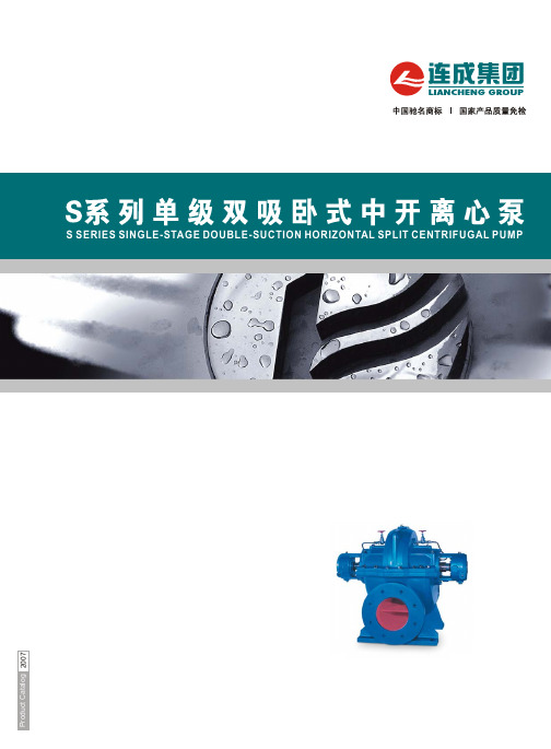
概述S(SM、SF、SY)型泵系更新换代的高效节能新产品,其适用范围比SA、SH更加广泛。
它采用国家标准规范设计,其系列化、标准化、通用化程度高,该型泵性能先进、运行平稳、安全可靠,在设计中采用新结构、新材质,可适用多种介质的输送。
S型泵供输送清水或物理化学性质类似于水的液体。
SM型泵是针对泥沙河流及类似水质的特点,在S型泵基础上采用新型抗磨结构及材质而设计的新产品,用于多泥砂介质的输送。
SF型泵是S型泵基础上采用耐腐蚀材质及机械密封结构而设计的新产品,用于各类腐蚀介质和油品的输送。
SL型泵是在S型泵的立式安装型可节省泵房面积。
仅适用于特殊场合,具体安装型式及要求与本公司协商确定。
SY型泵是S型泵基础上采用机械密封和外加冷却系统,用于各类油品的输送,并可以采用各种材质。
S、SM、SF、SL、SY型泵,广泛用于城市给排水、电站、工业流程系统的取水、加压、农田排灌及各种水利工程、石化工程。
性能范围;流量50~15000m3/h 扬程;8.6~140m 温度≤80℃也可根据用户要求设计性能参数。
过流材质;S型泵;铸铁SY、SM型泵;球墨铸铁,铸钢及不锈钢。
SF型泵;NiCr铸铁,不锈钢。
也可根据用户要求采用不同材质。
泵旋向;从电机端看,泵顺时针旋转(也可根据用户要求设计)GENERALS.(SM. SF. SY. SL)Series pumps are single, double suction and split case centrifugal pump and are used to pumping clean water or similar liquids in physical and chemical properties The temperarure of the pumped liquids should not be exceeded 80℃. And the pump is mainly suitable for water supply in factories, mines, cities, hydropower stations, various conservancy projects and irrigation in farms etc.泵型号意义例500S(SM、SF、SL、SY)35A500—泵的吸入口径(mm )S—单级双吸,中开离心清水泵,(SM为耐磨型,SF为耐腐型,SY输油型,SL为立式型泵)。
SS、SSL型离心泵安装,操作和维护手册

◆ 正确安装 ◆ 启动程序 ◆ 操作程序 ◆ 常规维护 ◆ 泵的大修 ◆ 故障分析 ◆ 订购备件或配件
2
目录
1 安全…………………………………………………………………4 2 概述…………………………………………………………………5 3 安装…………………………………………………………………7 4 操作 ………………………………………………………………13 5 预防性维护 ………………………………………………………18 6 拆卸和重新组装 …………………………………………………23 7 备件 ………………………………………………………………41 8 附录 ………………………………………………………………47
使用小心一词是为了指出假如忽视该
通用的预防措施
假如不遵守本手册中概括的程序将导 致人身伤害。
★ 未正确安装联轴器护罩,不得启动泵。 ★ 事先未向山东双轮集团咨询,不得超过
所购泵的额定条件运行泵。 ★ 未正确灌泵(泵壳中有足够的液体),不
得启动泵。
★ 低于推荐的最小流量或在没有液体时, 不得运转泵。
★ 在进行泵的维护之前,必须切断电源。 ★ 未安装安全设施时不得启动泵。 ★ 出口阀关闭时不得使泵长时间运行。 ★ 进口阀关闭时不得启动泵。 ★ 未经授权的山东双轮集团代表的批准,
密封腔……SS、SSL 系列单级双吸离心独
特的密封体设计,既可以使用填料密封,也 可以使用机械密封。
叶轮……叶轮是闭式结构,并靠键驱动。
本系列的泵共 69 种规格,分成 6 个轴承体: 轴承体……两端轴承体采用配合止口定
SS-40 轴承体………18 种规格
位。轴承体设有冷却腔,可以对轴承进行冷
SS-50 轴承体………18 种规格
wl-z190s循环水说明书
wl-z190s循环水说明书摘要:一、产品简介二、安装步骤三、操作与维护四、故障处理与维修五、安全注意事项正文:【一、产品简介】Wl-z190s循环水泵是一款高效、节能的循环水泵,广泛应用于工业、农业、建筑等领域。
本说明书将为您提供关于产品的安装、操作、维护及安全等方面的详细信息。
【二、安装步骤】1.准备工作:确保安装地点稳固,泵基础硬化平整,电源供应正常。
2.拆箱检查:检查泵内外零件是否有损坏,确认配件齐全。
3.泵安装:将泵置于基础上,安装泵壳、电机、联轴器等部件。
4.管道连接:按照设计图纸连接进水、出水管道,注意密封良好。
5.电机接线:按照电气原理图接线,确保接线正确无误。
6.试运行:启动电机,检查泵是否能正常工作,如有异常声音或震动,立即停机检查。
【三、操作与维护】1.启动:确认电源、管道连接无误后,启动电机。
2.停止:停止电机前,先关闭进水阀门,待泵内水排空后再停机。
3.定期检查:定期检查泵内外零件磨损情况,及时更换密封件和易损件。
4.清洁保养:定期清理泵内外污垢,保持泵的正常运行。
【四、故障处理与维修】1.故障处理:遇到故障时,立即停机检查,找出问题根源。
2.维修:根据故障情况,更换相应零件,维修后进行试运行。
【五、安全注意事项】1.安装、操作、维修时,必须确保电源切断,防止触电。
2.泵运行时,严禁将手或身体部位伸入泵内,防止受伤。
3.定期检查电源线路,确保安全可靠。
4.遇到突发情况,立即停机并采取相应措施。
请根据以上说明进行操作,确保Wl-z190s循环水泵的安全、稳定运行。
S泵安装说明书

• 安装类型D和H: 见章节 6.5 干式安装。
警告 在运行期间,冷却套管内必须注满冷却液体,以确保 充分冷却。 在首次启动之前以及长时间停机之后,必 须通过空气排气阀将冷却套管内的空气排出。
• 安装类型ST: 液位必须在水泵进口上方不小于900-1100 mm处。见图 21。
2.3.3 压力版本 见章节 4. 安全。
9. 控制单元必须保护WIO不会被它所连接的电源的短 路电流损坏。 由控制单元而来的最大电流不能超过 350 mA。
10. 最大潜水深度为20米。
警告 针对安全使用WIO传感器需要注意的特殊情况如下: 1. 控制单元必须保护传感器不会被它所连接的电源的
短路电流损坏。
2. 传感器的安装必须能够避免机械冲击危险。 3. WIO传感器不得用于自燃温度低于250 °C的油。
5. 泵送液体的液位必须由与电机控制回路连接的液位 开关来控制。 最低液位取决于安装类型,其规格在 本安装与操作指导中作出说明。
6. 避免水泵出现干运转的情况。
7. 确保永久安装的电缆受到恰当的机械保护,并连接 到对应的端子接线板上。
8. 污水泵的环境温度范围是 0 至 40 °C,且最大流程 温度为 40 °C。
警告 如果不遵守这些操作指导会有触电危险并造成严重的 人身伤害或死亡后果。
警告 该产品的表面十分灼热可以引起烫伤或其它人身伤害。
警告 高声压级,必须使用听力保护。
小心 不执行这些安全须知可能会导致故障发生或设备损坏。
注意 可以使工作简化和保证安全的注意事项或须知。
2. 概述
本手册对配备功率为55至520 kW电机的格兰富S系列污水及废水泵 的安装、操作及保养进行了说明。
图 4 显示72扬程水泵的认证标牌,该系列水泵可选择配备达到T3或 T4温度等级的电机。
水泵安装使用说明书

水泵安装使用说明书一、产品简介本水泵是一种高效、可靠的水泵,用于各种工业和家庭应用,主要用于水的输送和循环。
本说明书将为您提供有关水泵的安装和使用方法的详细指导,请仔细阅读以下内容。
二、安装1. 确保在安装水泵之前断开电源,并确保所有的阀门都处于关闭状态。
2. 按照提供的安装图纸确定水泵的安装位置,并确保该位置具有良好的通风和排水条件。
3. 将水泵的底座固定在坚固而平坦的地面上,使用螺栓将其牢固固定。
4. 按照电气连接图纸的指示,将水泵正确地连接到电源。
请务必遵循正确的电气接线程序,以确保安全。
5. 在水泵进口和出口管道上安装适当的管件,检查所有的密封件,确保气密性和水密性。
三、使用方法1. 在使用水泵之前,请打开相应的阀门,并确保系统压力达到正常水位。
2. 检查水泵的出口和进口是否有任何堵塞物,以避免对水泵产生不必要的负荷。
3. 打开水泵的电源,等待数分钟,确保水泵正常运行并无任何异常噪音。
4. 检查水泵的运行状态,确保其运转平稳,并根据需要调整出口压力。
5. 在使用过程中,注意观察水泵周围的温度和噪音,如有异常情况,请立即关闭电源并检查故障原因。
6. 定期清洁水泵,并检查密封件和管道连接是否正常。
四、维护保养1. 定期检查水泵的运行状态,注意观察噪音和振动情况,如发现异常,请立即停止使用并进行维修。
2. 定期清洁水泵的过滤器,并确保水泵周围没有杂物。
3. 定期检查水泵的轴承和密封件,如发现损坏或磨损,请及时更换。
4. 如需进行维护和保养,请务必断开电源,并等待水泵冷却后再进行操作。
五、安全提示1. 在操作水泵之前,务必确保已断开电源。
2. 在清洁和维护水泵时,注意避免接触水泵的运转部件,以免发生意外。
3. 定期检查电源线路的接地情况,确保安全运行。
4. 如需进行任何维修和更换部件,请务必遵循官方的维修指南或请专业人士进行操作。
六、故障排除以下为一些常见故障和可能的解决方法:1. 水泵无法启动:检查电源是否供电,检查电源线路是否有故障。
- 1、下载文档前请自行甄别文档内容的完整性,平台不提供额外的编辑、内容补充、找答案等附加服务。
- 2、"仅部分预览"的文档,不可在线预览部分如存在完整性等问题,可反馈申请退款(可完整预览的文档不适用该条件!)。
- 3、如文档侵犯您的权益,请联系客服反馈,我们会尽快为您处理(人工客服工作时间:9:00-18:30)。
19
10.3 受污染的泵
20
11. 故障查找表
21
12. 回收处理
21
警告
装机前,先仔细阅读本安装操作手册。 安装和运行必 须遵守当地规章制度并符合公认的良好操作习惯。
1. 本文献中所用符号
警告 不执行这些安全须知可能会引起人身伤害。
警告 使用防爆泵时必须遵守这些操作指导。 使用标准泵时 也建议按照这些指导进行操作。
12
6.5 干式安装
12
7. 电机保护
13
7.1 IO 113
13
7.2 SM 113
13
7.3 开关和传感器
14
8. 电气连接
15
8.1 电源线横截面
15
8.2 传感器接线图
16
8.3 变频器操作
17
9. 启动
17
9.1 检查旋转方向
17
10. 保养和维修
18
10.1 检查油位并更换机油
18
10.2 检查并调整叶轮间隙
9. 控制单元必须保护WIO不会被它所连接的电源的短 路电流损坏。 由控制单元而来的最大电流不能超过 350 mA。
10. 最大潜水深度为20米。
警告 针对安全使用WIO传感器需要注意的特殊情况如下: 1. 控制单元必须保护传感器不会被它所连接的电源的
短路电流损坏。
2. 传感器的安装必须能够避免机械冲击危险。 3. WIO传感器不得用于自燃温度低于250 °C的油。
警告 如果不遵守这些操作指导会有触电危险并造成严重的 人身伤害或死亡后果。
警告 该产品的表面十分灼热可以引起烫伤或其它人身伤害。
警告 高声压级,必须使用听力保护。
小心 不执行这些安全须知可能会导致故障发生或设备损坏。
注意 可以使工作简化和保证安全的注意事项或须知。
2. 概述
本手册对配备功率为55至520 kW电机的格兰富S系列污水及废水泵 的安装、操作及保养进行了说明。
图 1 S泵,量程72
序号
1 2 3 4 5 6 7 8 17
描述
进水口 出水口 电源电缆 控制电缆 吊耳 接线盒 潜水式电动机 泵 排气阀
TM03 1507 1110
2
中文 (CN)
警告 针对安全使用S泵 (量程为72防爆、74和78)需要注 意的特殊情况如下: 1. 确保湿敏开关与热敏开关分别与不同的电路连接,
警告 对于防爆泵型,安装现场的环境温度必须在 0 至 40 °C 之间。
泵送液体的密度和粘度 密度:1000 kg/m3。 运动粘度:1 mm2/s (1 cSt)。
泵送密度和/或运动粘度高于上述数值的液体时,请使 注意 用与其适配的高输出电机。
2.3.1 安装深度 最大潜水深度为20米。 2.3.2 泵送液体的液位
附件 自动耦合装置
自动耦合装置 用于立式安装的底座 用于卧式安装的底座 座圈
2.2 潜在爆炸性环境
在潜在爆炸性环境中,只能使用具有防爆认证的设备。 所有72扬程 的泵均有防爆版本。 72扬程防爆泵可用于1区或2区危险场。
注意 74和78扬程泵没有通过防爆认证的版本。
2.3 工作环境
pH 值 所有型号水泵均适用于pH值为4至10的液体泵送作业。 液体温度 容许温度为0-40 °C。
GRUNDFOS 说明书
S pumps, ranges 72-74-78
S2, S3, S4, ST 55-520 kW
安装和使用说明书
中文 (CN)
中文 (CN) 安装和使用说明书
中文版本。
目录
页
1. 本文献中所用符号
2
2. 概述
2
2.1 应用:
3
2.2 潜在爆炸性环境
3
2.3 工作环境
3
2.4 声压等级
警告 安装类型S和C的水泵应始终浸没在泵送的液体中,以 防止发生爆炸。
最大颗粒尺寸: 90-145毫米,取决于叶轮类型。
安装类型 S
C D H ST
描述
在自动耦合装置上进行潜 水安装的不含冷却套管的 污水泵。
在自动耦合装置上进行潜 水安装的配备冷却套管的 污水泵。
采用干式、立式安装的配 备冷却套管的污水泵。
采用干式、卧式安装的配 备冷却套管的污水泵。
安装在立式扬水管内的不 配备冷却套管的污水泵。
4. WIO传感器已根据EN/IEC 60079-18:2004标准进行 认证。在Ex和IEC Ex应用中,根据EN/IEC 6007918:2004标准要求,供应给传感器的电流必须限制 在350 mA以下。
2.1 应用:
量程为72、74和78的S泵适用于公共设施和工业应用中的污水及废 水泵送设计。 水泵具有多种安装方式,包括潜水式、干式、卧式以及立式安装。
警告 防爆电机在运行过程必须完全潜水。
警告 必须安装一个附加液位开关,以确保在停止液位开关 失效的情况下水泵仍可停止。
为避免空气被吸入泵,以及确保电机工作时能适当的降温,须遵守 下列基本要求: • 安装类型S:
对于S1运行(连续运行), 水泵的泵送液体必须始终淹没电机顶 部。见图 2。另见章节 9.1 检查旋转方向。
5. 泵送液体的液位必须由与电机控制回路连接的液位 开关来控制。 最低液位取决于安装类型,其规格在 本安装与操作指导中作出说明。
6. 避免水泵出现干运转的情况。
7. 确保永久安装的电缆受到恰当的机械保护,并连接 到对应的端子接线板上。
8. 污水泵的环境温度范围是 0 至 40 °C,且最大流程 温度为 40 °C。
4
3. 标识
5
3.1 型号
5
3.2 铭牌
6
3.3 合格牌照,扬程 72
6
3.4 防爆证书和防爆等级
6
4. 安全
7
5. 运输与存放
7
5.1 起吊泵
7
5.2 将泵提升10
6.1 安装类型
10
6.2 启动液位和停止液位
12
6.3 在自动耦合系统上的潜水安装
12
6.4 圆筒管安装
并且拥有单独的警报输出 (电机停止),从而避免 电机内部出现湿度或者温度过高的情况。
2. 替换螺栓的等级必须达到符合EN/ISO 3506-1标准 的A4-80 或A2-80。
3. 电机的火焰通道间隙偏窄,具体尺寸需由制造商详 细说明。 请参见制造商的安装、操作和保养指导文 件。
4. 冷却套管安装完毕后应将管内注满泵送液体。
在特殊情况下,如果电机没有满载运行,泵送液体的 注意 温度可能更高。
如有必要,请联系最近的格兰富公司或维修站。
警告 防爆型水泵不可泵送温度高于40 °C的液体。
环境温度 容许温度为0-40 °C。
在特殊情况下,如果电机没有满载运行,环境温度可 注意 能更高。
如有必要,请联系最近的格兰富公司或维修站。