基于单片机的智能灭火小车设计
智能灭火小车的设计与实现

随着社会经济和科学技术的快速发展,化工行业危险化学品和放射性物质泄漏、燃烧及爆炸等事故的隐患逐渐增加,一旦发生火灾,往往会带来巨大的人员伤亡和财产损失,因此开发一款智能设备用于实时监测火灾隐患并代替人工进行灭火,具有重要的现实意义[1]。
1总体方案设计笔者设计了一个智能灭火小车,其总体方案设计如图1所示。
发生火情后,火源检测模块发送信号给单片机,单片机判断后驱动电机前往火源处,途中遇到障碍物后会及时躲避,到达火源后驱动风扇进行灭火。
图1智能灭火小车总体方案设计2系统硬件部分2.1电源电路电源电路(图2)设计选用7805芯片。
7805智能灭火小车的设计与实现张博1,2邓治岗3巨永锋1吕建新2(1.长安大学电子与控制工程学院;2.西安思源学院工学院;3.西安航天动力试验技术研究所)摘要设计了一个以单片机为核心的智能灭火小车,利用红外接收二极管实现对火源的检测,利用红外传感器实现避障。
给出了智能灭火小车系统的软硬件部分和具体的调试过程。
实验结果表明,该小车通过检测火源,将采集到的数据传给单片机,驱动小车寻找火源并进行相应的避障,最后完成了灭火工作并返回。
关键词灭火小车单片机红外接收二极管红外传感器避障中图分类号TH862文献标识码A文章编号1000⁃3932(2020)04⁃0341⁃05作者简介:张博(1994⁃),硕士研究生,从事嵌入式系统的研究。
通讯作者:巨永锋(1962⁃),教授,从事自动控制、智能测控技术的研究,************.cn。
图2电源电路芯片有3个引脚,分别为终端输入端、输出端和地面接地端[2]。
通常情况下,该芯片可提供的最大电流为1.5A,输入电压可以为9、12、15V,输出电压为5V,且误差不超过±0.2V[3]。
综合考虑后, 7805芯片采用电池供电,选择9V的输入电压。
2.2电机驱动电路电机驱动电路(图3)采用L298电机驱动芯片。
电机调速采用PWM调速原理,电机的速度与占空比成正比关系[4],利用该比例关系可以控制电机的转速从而达到灭火的目的。
基于单片机的智能灭火小车设计与实现论文
摘要:该设计应用AT89C51,可以与数码显示管、电路等相结合的元件作为小车的控制核心,可以与数码显示管、电路等相结合。
基于单片机设计,AT89C51作为报警装置的控制器,可以充分运用AT89C51的数据处理和实时控制功能,让小车处于最好的状态。
当电机信号产生驱动灭火小车行进时,根据寻迹模块的红外对管能否寻到黑线产生的高低电平信号再传送到单片机,单片机根据程序设计要求做出相应的判断送给电机驱动模块.让小车在黑线上实现运行及转向的功能。
通过超声波传感器接受到障碍物信号,实现超声波避障功能。
通过红外传感感知温度,实现小车的灭火功能。
关键词:单片机路况检测报警超声波灭火Speech Control Robot based on STM32Abstract:This design USES AT89C51 as the control core of the car, and digital display tube, circuit, etc. Based on MCU design, AT89C51 as the controller of the alarm device, can fully AT89C51 data processing and real-time control functions. Keep the car in top condition. When the motor signal is generated to drive the fire fighting cart, the high-low level signal generated by the black line can be detected by the infrared pair tube of the tracing module and then transmitted to the MCU, which makes the corresponding judgment according to the program design requirements and sends it to the motor drive module to realize the function of running and turning on the black line. Ultrasonic obstacle avoidance function is realized by receiving the obstacle signal through ultrasonic sensor. The fire extinguishing function of the car is realized by sensing the temperature with the infrared sensor.Key words:Single chip microcomputer tracking alarm ultrasonic目录前言 (2)1 方案设计 (4)1.1 方案论证 (4)1.1.1 控制器的选择与论证 (4)1.1.2 电机驱动芯片的选择与论证 (4)1.1.3 显示器件的选择与论证 (5)1.1.4 路况检测模块 (5)2 系统硬件电路与实现 (5)2.1 红外遥控及解码模块 (5)2.2 红外遥控模块及解码模块 (6)2.2.1 二进制信号的调制 (6)2.2.2 二进制信号的解调 (7)2.2.3 二进制信号的解码 (7)2.3 单片机红外硬件电路的实现 (8)2.4 电机驱动智能灭火模块 (8)2.5 路况检测模块 (11)2.6 智能防撞报警模块 (12)3 系统软件设计及实现 (14)3.1 红外整体程序 (14)3.2 红外遥控的解码和实现 (15)3.3 电机驱动灭火 (16)3.4 小车防撞报警 (17)4 系统调试 (18)4.1 遥控发送接收调试 (19)4.2 灭火驱动调试 (20)5 总结 (22)前言在现代社会,单片机技术发展迅速,机械电子技术逐步融合,自动控制技术在工业中的地位已经变得非常重要。
基于STM32 的喊话救援小车设计
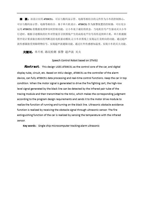
基于STM32 的喊话救援小车设计图1 消防侦察机器人除上述消防小车侦查机器人外,当前消防排烟机器人与消防灭火机器人也渐渐得到应用,如图2—3所示。
其主要实现灭火、排烟、降毒等功能,每台重量达千斤,需用卡车运输,由消防员操作无线遥控掌握方向,开启排烟或喷水系统。
受体型空间限制,该机器人通常在火灾建筑物周边移动,生产厂家主要为中信重工[6]。
图2 消防排烟机器人图3 消防灭火机器人目前,智能小车讨论和应用较为广泛,依据文献和网络资源的检索,消防智能小车讨论主要集中在:(1)消防小车的路线寻迹避障;(2)火情现场的灭火机制机构。
二者的讨论重点均为如何毁灭火情,对于长时间的灭火,忽视了灭火所需的原料与电源,如泡沫、水罐和干粉等耗材会限制智能消防小车的使用。
除此之外,对智能小车而言,喊话救援功能比灭火救援更具有有用价值[7-9]。
在无法得知火场内部状况时,外部指挥人员掌握小车进入火场内,并播放逃命指引,被困人员可以根据指引方法逃命。
通过监控系统对火场内部的环境和火情进行摄像,并将视频由通信系统传送至外部的指挥员处,便利外部指挥员了解火场内状况。
社会经济日益进展,某些建筑在拥有巨大社会效益和经济利益的同时,也伴随着巨大的风险导致危急物品和易燃易爆物质发生燃烧、爆炸等。
一旦发生灾难,消防员必需冒着生命危急完成任务。
近5 年中,年均20 万起火灾数量、有30 位消防人员牺牲,因火情受伤更不在少数。
如何降低火灾发生率和提升消防队员平安系数的问题急需解决,若是有了先进的“小车”帮助消防员,在提升效率的同时也能提升营救的平安系数。
2 喊话救援小车的设计2.1 本项目的设计思路和方法基于本项目主要功用是替代和帮助消防员作业,在受困人心情紧急不知所措的前提下指引逃命。
本设计采纳STM32F105 单片机实现,掌握电机驱动系统,调整4 个麦轮的转向与转速,调整喊话救援内容。
电源采纳24 V 动力锂电池供电,摄像模块完成图像采集,存储到存储器并放射至掌握操作员端,操作员掌握转向模块调整摄像区域,声放模块播放逃命指引,拾音模块收集火情现场声音信息,操作员依据声音信息进行直接喊话救援。
基于单片机的智能小车的设计毕业论文总

基于单片机的智能小车的设计-毕业论文-总————————————————————————————————作者:————————————————————————————————日期:基于单片机的智能小车的设计摘要单片机作为一种微型控制器,自走入人们的视野以来,就随着科技进步不断地更新换代。
它能够将计算机所有关键的零件整合集中在一块芯片上,并且具有强大的计数功能,以及各种必要的接口,因此单片机在自动控制系统中通常处于核心地位。
本文对于智能小车的设计思路就应用了最常见的AT89S51单片机作控制处理器,该单片机在低功率的基础上,能够保持其性能在一个较高的水平上,且其8K的处理器够灵巧,适用于嵌入式产品,在众多单片机中,表现较为优秀。
本设计是在单片机的基础上实施的,兼具数据处理、即时调控和报警提醒功能,小车接到行驶指令后,红外探头会检测路况信息(是否处在黑线路径范围内)并反馈给单片机处理,单片机判断后作出相应指令,由电机驱动使小车执行相应行驶动作。
单片机与系统的配合使智能小车的行驶保持灵敏迅速的状态。
关键词:单片机寻迹报警红外线电机驱动AbstractWith the rapid development of science and technology in recent years,SCM applications arecontinually deepen ing.Traditionalcontroltest drive at the same ti me, the rapidly growing update. In real-timedetect ionandcontrolof the microcomputer application system,the microcontrolleris oftenused asacore component.SCM is the main featureint egrated computer chip ina micro-computer. Itis a setof multi-counting and the interface in oneof the micro-controller. The 51 single-chip microcontroll eris the mosttypical andmost representative one.Thedesignof the mainapplicationAT89S51asthecontrol,anddisplaydriverintegratedcircuit sand other systems.Based on single chipdesign.MCUAT89S51 using the controlleras an alarm device that can givefull playto AT89S51ofdata processing and real-time control functions.Make the system work in the bestcondition,improvethesystem sensit ivity.Whentwo signal driven forward bycar tracing module,theinfrares onwhether to producelevel signalsthrough the black,retutn again according to requirement ofdesign procedure of judgment for motor drivermodule,itcontrolsthe car turning back forward ofrunning onthe blackline.Keywords:SCM,Tracing, Alarm device,Levelsignals,Motor driver module目录摘要ﻩ错误!未定义书签。
基于单片机的智能小车的设计

基于单片机的智能小车的设计智能小车在当今社会中得到越来越广泛的应用,它不仅可以为人们的生活带来方便,还能在工业生产和科研领域发挥关键作用。
而基于单片机的智能小车设计是其中的一个重要方面,它通过利用单片机的高度集成和强大功能,实现智能小车的自主控制和感知任务。
本文将深入探讨基于单片机的智能小车设计的关键技术和发展趋势,为读者提供一些有益的参考和启发。
智能小车的设计中,传感器是至关重要的一环。
而对于基于单片机的智能小车来说,选择合适的传感器和设计有效的传感器数据采集方案显得尤为重要。
在传感器选择方面,常用的传感器有红外传感器、超声波传感器、光电传感器等,它们可以实现对障碍物的检测和环境信息的感知。
在传感器数据采集方案设计上,需要考虑到传感器数据的采集频率、传感器数据的处理方式以及传感器数据与单片机的接口方式等。
通过合理设计传感器的选择和数据采集方案,可以有效提高智能小车的感知能力和控制精度。
除了传感器外,基于单片机的智能小车设计还需要考虑到智能控制算法的设计。
智能控制算法是实现智能小车自主行驶和避障的核心,它可以通过对传感器数据的处理和分析,实现对小车行驶方向和速度的实时控制。
常用的智能控制算法包括PID算法、模糊控制算法和神经网络控制算法等,它们分别适用于不同的应用场景和控制需求。
在智能控制算法的选择和设计中,需要考虑到算法的实时性、稳定性和可调节性,以实现对智能小车的精确控制和智能决策。
在设计基于单片机的智能小车时,硬件设计也是一个不可忽视的方面。
合理的硬件设计可以有效提高智能小车的性能和稳定性,为控制算法的实现提供良好的硬件支持。
常用的硬件设计包括电机驱动电路设计、电源管理电路设计和通信接口电路设计等。
其中,电机驱动电路设计是最为关键的一环,它可以实现对小车电机的精确控制和驱动,保证小车的行驶稳定性和速度调节精度。
电源管理电路设计则是保证小车电路的稳定供电和功耗管理,避免因电路供电不稳定导致小车控制系统工作异常。
基于STM32的智能消防小车设计--外文翻译

基于STM32的智能消防小车设计--外文翻译本科生毕业论文(设计)专业文献翻译题目: 基于STM32的智能消防小车设计姓名:学院:专业:班级:学号:指导教师: 职称:20 年月日教务处制A. Introduction of STM32STM32 is based on the family of ARM Cortex-M3 core - designed specifically for embedded applications that require high performance, low cost, low power consumption. The performance is divided into two different series: STM32F103 the "Enhanced" series and STM32F101 the "Basic" series. The clock frequency of Enhanced Series is up to 72MHz, the highest performance of similar products; the clock frequency of Basic Series is 36MHz, and the prices of 16 position products significantly enhance the performance of more than 16 position products, is the best choice users to buy them. The two series arebuilt-in flash from 32K to 128K, is the combination of the maximum capacity of the SRAM and peripheral interfaces. When the clock frequency reaches 72MHz, it executes from Flash and the STM32 power consumption is 36mA, the lowest power consumption in the 32-bit market products, the equivalent an impressive 0.5mA/MHz.a. STMicroelectronics GroupSTMicroelectronics Group was established in June 1987, is a merger of Italy's SGS Microelectronics and the French Thomson semiconductor company. In May 1998, SGS-THOMSON Microelectronics will change the company name to STMicroelectronics Limited. STMicroelectronics is one of the largest semiconductor companies in the world. From its inception to date, ST'senergy-saving architecture to deliver industry-leading energy-saving performance. This series belongs to the lineup 32 STMicroelectronics STM32 microcontroller product family, the product family, a total of 180 balance of product, the full range of products share most of the pin, software and peripherals, excellent compatibility with developers to the maximum design flexibility.c. ST ultra-low-power ARM ® Cortex ™-M0 microcontrollerSTM32F0 series of products are based on the ultra-low-power ARM Cortex-M0 processor core technology and features, enhanced integration, aimed at the application of ultra-low-cost budget. The family of microcontrollers to shorten the 8-bit and16-bit micro-controller devices and the performance gap between the 32-bit microcontroller device, the user terminal products in the economy to achievestate-of-the-art complex features.d. ProductsBefore STM32F105 and STM32F107 interconnect family of microcontrollers, STMicroelectronics has introduced the STM32 Access Line Enhanced Series, the series of the USB basic series and enhanced; new products follow the Enhanced Series 72MHz processing frequency. Memory 64KB to 256KB Flash and 20KB to 64KB embedded SRAM. The LQFP64, LQFP100, and LFBGA100 three package in the new series, a different package to maintain the pin out consistency, combined with the STM32 platform design philosophy,and developers by selecting the products can be re-optimization function, memory, performance and pin count, with a minimum of hardware changes to meet individual application needs.Until July 1, 2010, the circulation of models:Basic: STM32F101R6 STM32F101C8STM32F101R8 STM32F101V8 STM32F101RBSTM32F101VBEnhanced: STM32F103C8 STM32F103R8 STM32F103V8 STM32F103RBSTM32F103VBSTM32F103VE STM32F103ZESTM32 models Description:STM32F103RBT6 chip model, for example, the compositions of the models of seven parts, its naming rules are as follows:(1) STM32: STM32 ARM Cortex-M3represents kernel of 32-bit microcontrollers.(2) F: F represents the chip sub-series.(3) 103:103 representatives Enhanced Series.(4) R: R This is a representative of the number of pins, where T represents 36 feet, 48 feet, C represents, R represents a 64 feet, V represents the 100-pin 144-pin, Z represents.(5) B: B a representative of embedded Flash capacity, including 6 on behalf of 32K bytes of Flash, 8 on behalf of 64K bytes Flash, 384K bytes Flash B on behalf of 128K bytes Flash, C on behalf of 256K bytes Flash, D representatives E on behalf of 512K bytes Flash.(6) T: T a representative of the package,in which H represents BGA package, T represents LQFP package, U represents VFQFPN package.(7) 6:6 This is a representative of the operating temperature range, where 6 represents -40 - 85 ℃, 7 on behalf of -40 - 105 ℃.e. STM32F103 performance characteristicsFeature1. The kernel: ARM32-bit Cortex-M3 CPU, the maximum operating frequency of72MHz,1.25DMIPS/MHz. Single-cycle multiply and hardware division.2. Memory: integrated on-chip 32-512KB of Flash memory and 6-64KB SRAM memory.3. Clock reset and power management: 2.0-3 .6 V drive voltage of the power supply and I / O interface, POR, PDR andprogrammable voltage detector (PVD),4-16MHz crystal oscillator, embedded 8MHz RC oscillator tuning circuit in the factory, 40 kHz internal RC oscillator circuit. For the CPU clock PLL. With the calibration for the RTC 32kHz crystal.4. Low power consumption: three kinds of low-power modes: Sleep, stop, standby mode. Powered the VBAT RTC and backup registers.5. Debug mode: serial debug (SWD) and JTAG interfaces.6. DMA: 12-channel DMA controller; supported peripherals: timers, ADC, DAC, SPI, IIC and USART.7.2 12 us class A / D converter(16-channel): A / D measurement range:0-3 .6 V. Dual sample and hold capability. The chip integrates a temperature sensor.8. 2-channel 12-bit D / A converter: STM32F103xC STM32F103xD STM32F103xE unique.9. A maximum of up to 112 fast I / O ports: Depending on the model, 26,37,51,80, and 112I / O ports, all ports can be mapped to the16 external interrupt vector. In addition to the analog input can accept less than 5V input.10. A maximum of up to 11 timers: four 16-bit timers, each timer 4 IC / OC / PWM or pulse counter. Two 16-channel advanced control timer: up to 6 channels for PWM output. 2 watchdog timers (independent watchdog and window watchdog). Systick timer: 24-bit down counter. Two 16-bit basic timer is used to drive the DAC.11. A maximum of up to 13 communicationinterfaces: two IIC interface (SMBus / PMBus), 5 USART interface (ISO7816 interface, LIN, IrDA compatible, the debugging control), Three SPI interface (18 Mbit / s), two and IIS reuse, CAN interface (2.0B), USB 2.0 full-speed interface, SDIO interface.12. ECOPACK package: STM32F103xx family of microcontrollers ECOPACK package.System role1. Integrated embedded Flash and SRAM memory, ARM Cortex-M3 core. And compared to the 8/16 devices, the ARM Cortex-M3 32-bit RISC processor provides a higher efficiency of the code. The STM32F103xx microcontroller with an embedded ARM core, so can be compatible with all ARM tools and software.2. Embedded Flash memory and RAM memory: built-up to 512KB embedded Flash, can be used to store programs and data. Up to 64KB of embedded SRAM can read and write to the clock speed of the CPU (not wait state).3. A variable static memory (FSMC): FSMC embedded in STM32F103xC, STM32F103xD, STM32F103xE, with four chip select support four modes: Flash, RAM, PSRAM, NOR and NAND. After OR after three FSMC interrupt lines connected to the NVIC. No read / write FIFO PCCARD outside, the code is executed from the external memory, and does not support the Boot took target frequency equal to SYSCLK / 2 Therefore, when the system clock is 72MHz, external access, according to 36MHz.4. Nested vector interrupt controller(NVIC): can handle 43 maskable interrupt channels (not including the 16 interrupt lines of Cortex-M3), provides 16 interrupt priority. Tightly coupled NVIC lower interrupt processing delay directly passed to the kernel interrupt entry vector table address, tightly coupled the NVIC kernel interface, allows interrupts to be anticipated, after the higher-priority interrupt handling support tail chain, automatically save the state of the processor, interrupt entry automatically resume when the interrupt exit, no instruction intervention.5. The external interrupt / event controller (EXTI): External interrupt / event controller for 19 to generate an interrupt / event request edge detectorlines. Each line can be individually configured to select the trigger event (rising edge, falling edge, or both), can also be individually shielded, a pending register to maintain the state of the interrupt request. When the external line appear longer than internal APB2 clock cycle pulse, EXTI is able to detect. Up to 112 GPIO connected to the 16 external interrupt lines.6. Clock and start: start or system clock selection, but reset when the internal 8MHz crystal was selected as the CPU clock. Can select one of 4-16MHz external clock, and will be monitored to determine whether successful. During this period, the controller is disabled and the software interrupt management subsequently also beprohibited. At the same time, if there is a need (for example, encountered an indirect use of crystal failed), PLL clock interrupt management fully available. Multiplepre-comparator can be used to configure the AHB frequency, including high-speed APB (PB2) and low-speed APB (APB1), high-speed APB highest frequency of 72MHz, low-speed APB highest frequency of 36MHz.7. Boot mode: startup, Boot pin is used to select one of three kinds Boot Options kinds: Import from user Flash memory from the system import, import from SRAM. The Boot import program is located in the system memory for Flash Memory Programming by USART1 re.8. Power supply program: VDD voltage range of 2.0V-3.6V, VDD pin provides an externalpower supply through, for I / O and internal regulator. VSSA and VDDA, voltage range of 2.0-3.6V, external analog voltage input for the ADC reset module, RC and PLL VDD range (ADC is limited to 2.4V); VSSA and VDDA must be corresponding connection to VSS and VDD. VBAT, the voltage range of 1.8-3.6V, VDD invalid for RTC, external 32KHz crystal oscillator and backup registers power supply (via the power switch to achieve).9. Power management: The device has a power-on reset (POR) circuit and power-down reset (PDR). This circuit has been used to ensure that the necessary operating from 2V starts fell to 2V. When VDD drops below a specific lower limit VPOR / PDR, without the need for an external reset circuit, the device can also be held in reset mode.Equipment specific to an embedded programmable voltage detector (PVD) PVD for detecting VDD compare and VPVD limit, will generate an interrupt when VDD to lower than VPVD or VDD greater than VPVD. Interrupt service routine can generate a warning message or MCU will be set to a safe state. PVD is enabled by software.10. Voltage regulator: The regulator has three operation modes: main (MR), low power (LPR) and power-down. MR used in the traditional sense of the adjustment mode (operating mode), LPR is used in the stop mode, power down in standby mode: regulator output is high impedance, the core circuit power-down; including zero consumption (the contents of the registers and SRAM will be lost).11. The low-power mode: STM32F103xx support three kinds of low-power mode, so as to achieve the best balance betweenlow-power, short start-up time and wake-up source available. Sleep mode: only the CPU stops working, all peripherals continue to run, wake up the CPU interrupt / event occurs; Stop mode: allows keeping the contents of the SRAM and registering with minimal power consumption. The 1.8V regions of the clock are stopped, the PLL, the HSI and the HSE RC oscillators are disabled, and the regulator is set to normal or low-power mode. The device can wake-up from stop mode by external interrupt lines. The external interrupt sources can make one of the 16 external interrupt lines, PVD output or TRC warning. Standby mode: the pursuit ofminimum power consumption, the internal voltage regulator is turned off, so 1.8V regional power outage. PLL, HSI and the HSE RC oscillators are also closed. Enter standby mode, in addition to backup register and Standby circuit, SRAM and register contents will be lost. When an external reset (NRST pin), the IWDG, reset, WKUP pin a rising edge or TRC warning occurs, the device out of standby mode. Enters the stop mode or standby mode, TRC, IWDG clock source does not stop.f. Architectural advantagesIn addition to the new features enhanced peripheral interface, STM32 interconnection series also provide the same standard interface with other STM32 microcontroller shared this peripheralenhance application flexibility of the entire product family, so that developers can multiple designs to repeated use of the same software. New STM32 standard peripherals include 10 timers, two12-Msample / s analog-to-digital converter (Interleaved 2-Msample / s mode), two 12-bit digital-to-analog converters, two I2C interface five the USART interface and three SPI ports. A total of 12 new products peripheral DMA channels, there is a CRC calculation unit, like other STM32 microcontroller supports 96 unique identification number.The new family of microcontrollers also has followed the STM32 product family of low-voltage and energy-saving advantages. The operating voltage range of 2.0V to 3.6V,compatible with mainstream battery technology, such as lithium batteries and nickel-metal hydride batteries, the package also features a battery mode dedicated pin V bat. 72MHz frequency code execution from flash consumes only 27mA of current.Low-power mode, there are four; the current consumption can be reduced to two microamps. Fast start from the low-power mode to save energy; start circuit STM32 internally generated 8MHz signal to wake up the microcontroller from stop mode with less than 6 microseconds.B. Introduction of Fire-fighting robotFire robot as a kind of special robots, increasingly play a pivotal role in the fire fighting and rescue. The various largepetrochemical enterprises, tunnels, subway growing oil gas, gas leak explosion, tunnel, subway collapse disaster growing.Fire-fighting robot instead of the fire and rescue personnel into the inflammable, explosive, toxic, hypoxia, smoke and other dangerous disaster scene of the accident data acquisition, processing, and feedback.a. Brief introductionFire robot as a special fire-fighting equipment can replace firefighters close to the scene of the fire to the implementation of effective fire fighting and rescue, chemical testing and fire reconnaissance. Its application will improve the fire brigade combat abilities in to Fight King vicious fire, will have an important role to reduce the loss of state property and fireand rescue personnel casualties.b. BackgroundWith the particularity of the rapid socio-economic development, construction and production, leading to the leakage of hazardous chemicals and radioactive substances as well as combustion, explosion, collapse potential accidents increase, the probability of accidents has correspondingly increased.The event of disasters and accidents, firefighters face of high temperature, dark, toxic and smoke harm the environment, if there is no corresponding device rashly rushed into the scene, not only can not complete the task, but also to create more casualties.Fire robot as a kind of special robots,increasingly play a pivotal role in the fire fighting and rescue. The various large petrochemical enterprises, tunnels, subway growing oil gas, gas leak explosion, tunnel, subway collapse disaster growing. Such disasters have a sudden strong, complex disposal process is dangerous, prevention difficulties, has become a chronic illness. Fire fighting robot can instead of the fire and rescue personnel into the inflammable, explosive, toxic, hypoxia, smoke and other dangerous disaster scene of the accident data acquisition, processing, feedback, to effectively address the personal safety of firefighters faced in these places, the lack of data acquisition and other issues. The site command personnel based on feedback, timely make a scientific judgment of thedisaster to make a correct and rational decision-making, the scene of the accident and disaster.c. History of developmentRobots since the early 1960s, the advent experienced more than 40 years of development, has made great progress in every walk of life can be found there. From the 1986 Tokyo Fire Department for the first time in the "Rainbow" robots are used in fire extinguishing, fire-fighting robot has been widely used in the field of fire fighting and rescue, fire-fighting robot technology has also been a rapid development. As of now, the fire-fighting robot has the steady development of third-generation high-end intelligent robot.In the face of relentless fire, theShanghai Fire Research Institute of Ministry of Public Security, Shanghai Jiaotong University, and Shanghai Fire Bureau to develop a plan for the development of fire-fighting robot. After three years of research, the first fire-fighting robot has been born. Fire fighting robot can walk, climbing, cross-barrier spray fire extinguishing and fire reconnaissance.一、STM32简介STM32系列基于专为要求高性能、低成本、低功耗的嵌入式应用专门设计的ARM Cortex-M3内核。
基于51单片机的智能小车设计报告

本人保证自写文档,文档不足之处请谅解目录一、设计的目的------------------1二、设计的模块------------------1三、程序的流程------------------6四、元器件清单------------------8五、成品的制作------------------8六、注意事项--------------------9七、设计的总结------------------9设计的目的智能遥控车地目的主要突出在智能与遥控上,遥控意思明显就是通过某种控制手段使得小车能够实现由控制者控制前进后退等操作;智能可以体现为功能上的智能化。
本作的目的是实现控制小车移动时对前方所存在的威胁进行报警提醒。
设计的模块此次设计的硬件电路模块大致为五大类,分别是51单片机最小系统模块、电源模块、电机工作驱动模块、超声波报警系统模块、无线控制发射接收模块。
下图为硬件电路框图:1、单片机最小系统此模块式是本设计的控制核心模块,单片机最小系统由三部分组成:STC89C52芯片部分、复位部分(由按键开关、极性电容、10K电阻组成)、晶振部分(由12M石英晶振、两个30PF的瓷片电容组成)。
主要起程序的输入与控制、程序的复位、时间频率控制的作用。
2、无线控制模块本设计的无线控制模块是由编码芯片PT2262和解码芯片PT2272组成的电路模块组成,工作方式是编码芯片PT2262 发出的编码信号由:地址码、数据码、同步码组成一个完整的码字,解码芯片PT2272 接收到信号后,其地址码经过两次比较核对后,VT脚才输出高电平,与此同时相应的数据脚也输出高电平,如果发送端一直按住按键,编码芯片也会连续发射。
3、电机驱动模块本设计是采用了L298N电机驱动模块来驱动减速电机工作;L298N是ST公司生产的一种高电压、大电流电机驱动芯片。
该芯片采用15脚封装。
主要特点是:工作电压高,最高工作电压可达46V;输出电流大,瞬间峰值电流可达3A,持续工作电流为2A;额定功率25W。
基于STM32的消防小车设计共3篇

基于STM32的消防小车设计共3篇基于STM32的消防小车设计1消防小车是一种可以在紧急情况下快速响应的灭火设备。
它可以在火场中进行精确定位和目标搜索,并通过自主导航技术和遥控操作实现火场内部和外部的水枪喷射。
今天,我将讨论基于 STM32 的消防小车设计。
1. 系统设计为确保消防小车的高可靠性和快速响应,我们需要采用分布式控制设计,将解决方案分为两个部分:①车体电控系统:这是消防小车的核心系统,采用STM32作为主控芯片,主要实现车体驱动、导航定位、图像采集和识别、云端数据传输等功能。
②远程控制系统:在消防小车实际应用中,操作员通常需要远程控制车辆,并与车载硬件实现实时通信。
因此,我们需要开发适用于手机或电脑的遥控软件,以保证消防工作人员能快速响应火灾。
2. 车体结构设计消防小车的车体设计应以易于操作和便于携带为原则。
基于这一原则,我们设计了以下结构:①底盘:采用四轮驱动的底盘设计,可以提高消防小车的悬挂性能和越野能力。
②上层机构:上层机构包括水泵、水管、水枪等配件。
水泵负责将水源(如消防水源或水箱)中的水通过管道送入水枪,以便消防工作人员进行灭火。
③传感器:传感器可用于检测温度、气体、光线等指标,从而实现对火场的实时监控,并及早发现潜在危险。
3. 系统硬件设计为了实现消防小车的各项功能,我们需要设计一系列的硬件模块,包括驱动模块、通信模块、电源模块和传感器模块等。
在STM32控制下,我们可以使用各种类型的传感器,如红外线传感器、超声波传感器、逐行扫描摄像头等,以便检测火点、障碍物、路线等信息。
此外,可以使用无线模块实现车载设备和操作员之间的实时数据传输,以支持火场内、外的联动操作。
4. 系统软件设计消防小车的软件系统包括车辆控制程序、导航程序、图像处理程序等多个模块。
这些程序的设计将为实现装备运行、路线规划、火情识别等任务奠定基础。
①控制程序:可实现车辆的前进、后退、左转和右转等基本功能,同时还可以启动水泵和水枪等硬件设备。
- 1、下载文档前请自行甄别文档内容的完整性,平台不提供额外的编辑、内容补充、找答案等附加服务。
- 2、"仅部分预览"的文档,不可在线预览部分如存在完整性等问题,可反馈申请退款(可完整预览的文档不适用该条件!)。
- 3、如文档侵犯您的权益,请联系客服反馈,我们会尽快为您处理(人工客服工作时间:9:00-18:30)。
基于单片机的智能灭火小车设计
摘要:如今,我国正处于经济迅猛发展的时期,人民的生活水平得到普遍提高,居住环境和生活环境也不断的改善,但同时,我国的消防安全隐患仍是个巨大的问题。
每年,我国的火灾事故频频出现,尤其是发生了重大火灾时,消防工作人员自身在抢救时也面临着生命的危险,甚至有时候根本无法达到目的地进行灭火抢救。
如何能在高效灭火的同时保障消防员的生命安全,是我们当今所考虑的问题,于是,当代人们想出了智能灭火小车,由机器代替人们进行一些不可完成的工作,同时也能减少生命和财产的损失。
关键词:智能灭火小车;MX1508;STC89C52
引言
基于单片机的智能灭火小车设计的研究背景,源于对火灾扑救效率和安全性的需求和对智能科技的追求。
通过单片机技术的应用,可以实现智能灭火小车的自主导航、实时感知、智能控制等功能,提高灭火效率和消防安全,同时也为智能科技的发展提供了基础和支撑。
本次设计的研究旨在设计一个基于单片机的智能灭火小车,能够实现火源的检测并且自动寻迹前往进行灭火。
并结合了蓝牙模块,可以实时向手机反馈小车的运转状况,也可以通过手机发送指令控制小车的运行。
1系统硬件介绍
1.1单片机最小系统
STC89C52单片机最小系统电路是一种基于STC89C52单片机的基本电路,包括STC89C52芯片、11.0592MHz晶振和复位电路。
晶振提供时钟信号,复位电路用于初始化单片机,为其提供稳定的工作环境,实现基本的操作和程序运行。
这个最小系统电路是STC89C52单片机开发和应用的基础。
1.2避障检测模块电路
HC-SR04超声波检测模块是一种常用的超声波测距模块,包含超声波发射器
和接收器。
它通过发射超声波脉冲并接收其回波来测量物体与模块之间的距离。
模块工作原理是通过发送一个短脉冲的超声波信号,然后计算从发射到接收回波
的时间差来确定距离。
HC-SR04模块广泛应用于无人机、机器人、智能小车等领域,提供非接触式、精确的距离测量功能。
HC-SR04超声波检测模块实物图如图1所示
图1 超声波检测模块实物图
1.3红外循迹模块电路
TCRT5000红外传感器是一种常见的红外线接收器模块,具有发射与接收功能。
它由红外发射二极管和光敏二极管组成,用于检测物体是否存在或通过红外光的
反射来测量距离[10]。
当红外光遇到物体并反射回传感器时,接收器将接收到的光信号转换为电信号,以便进行进一步的处理。
TCRT5000红外传感器广泛应用于避障、测距、物体检测和线路跟踪等项目中,是一种便捷而实用的传感器模块。
以上是对红外循迹模块的原理进行了说明,具体的模块实物图与接线图如图
2与3所示。
图2TCR500红外循迹模块实物图
图3 TCR500红外循迹模块接线图
1.4测速模块电路
测速模块是利用红外对射管传感器对此次设计的速度进行实时采集,然后发送给中央控制模块处理后,发送到显示模块显示。
测速原理为,当被检测的物体经过红外对射管传感器时,传感器会感受到光照的变化。
根据编码盘上黑白相间的区域,光照的变化会引起光电传感器输出电信号的变化。
通过测量输出信号的频率或脉冲数量,可以计算物体的转速或运动状态。
测速模块实物图与接线图如图6与7。
图6 测速模块实物图
图7 测速模块原理图
1.5火焰检测模块
火焰传感器是使用AC4067红外敏感型芯片对红外强度进行检测。
火焰传感器模块是一种用于家庭环境火焰监控的装置。
当物体燃烧时,会产生火焰,而火
焰的热辐射会生成具有一定波长的红外光。
这些红外光的波长通常在750~2500nm 范围之间,红外光具有较强的穿透能力,相对于可见光来说,其波长较长,不容易被吸收[12]。
火焰检测模块实物图与接线图如图8与9所示。
图8 火焰检测模块实物图
图9 火焰检测模块接线图
1.6蜂鸣器报警模块
本次设计中使用蜂鸣器模块作为报警进行设计,蜂鸣器报警模块是一种常见的声音输出设备,常用于各种电子设备和系统中作为警报或提示音的发声装置。
它通常由振膜、震荡电路和驱动电路组成[14]。
蜂鸣器的工作原理基于电磁感应和振动。
当电流通过蜂鸣器的驱动电路时,电流会产生磁场,这个磁场将与蜂鸣器内部的振膜相互作用。
振膜是一个薄膜,它由柔软的材料制成,可以随着电流的变化而振动。
在工作时,驱动电路会以一定频率产生电流,并通过电磁感应作用将振动传递给振膜。
振膜的振动会产生声波,从而产生可听到的声音。
蜂鸣器的声音频率取决于驱动电路产生的频率和振膜的振动特性。
蜂鸣器模块实物图与接线图如图12与13所示。
.
图12 蜂鸣器报警模块实物图
图13 蜂鸣器报警模块接线图
1.7蓝牙模块
此次设计采用ECB02作为此次设计的检测和控制系统,用户可以通过蓝牙连
接手机然后远程查看有关数据,并可以远程控制。
ECB02蓝牙模块采用了蓝牙技术标准,通常基于蓝牙2.1或更高版本的规范。
它具有低功耗、高速传输和广泛的通信范围等特点,可用于各种应用领域,如无
线数据传输、远程控制、传感器网络和物联网等。
蓝牙模块通常包括蓝牙芯片和相关的外围电路。
ECB02蓝牙模块具有一定的
处理能力和存储容量,可以支持蓝牙协议栈的运行,并提供与其他设备进行通信
所需的接口和功能。
在与单片机进行通信时,首先需要将蓝牙模块与单片机的UART接口进行连接。
通常,蓝牙模块具有TX(发送)和RX(接收)引脚,而单
片机也有相应的TX和RX引脚[15]。
蓝牙模块实物图与接线图分别如图14与15所示。
图14 蓝牙模块实物图
图15 蓝牙模块接线图
仿真及实验结果分析
2.1仿真
整体仿真电路图如图16所示,主要包括STC89C52单片机、超声波模块、电机驱动模块、一个继电器(用于控制灭火)、蓝牙模块、测速模块、声光报警电路。
图16仿真系统图
2.2实验结果分析
小车在正常行驶的过程中,通过一对红外寻迹管进行寻迹。
如果是实物进行测试,是将小车放置于绘制好黑线轨迹的跑道中,如果黑线在中间,小车正常前进,如果黑线在小车左侧,左侧红外对管感应到黑线,此时小车左电机反转,右电机正转,从而实现小车左转,反之小车右转。
从而在动态调节中使得灭火小车可以寻迹。
通过一对红外寻迹管进行寻迹,在寻迹过程中,通过超声波检测前方障碍物,当检测到障碍物距离小于50cm大于30cm,蜂鸣器报警当检测到障碍物距离小于等于30cm时,自动停车,直到障碍物移除。
通过火焰传感器检测是否发生火灾,发生火灾后,停车,闭合继电器进行灭火,直到火被熄灭,再继续前进。
系统通过蓝牙模块实时向手机传输小车状态信息,也可以通过蓝牙发送指令控制小车运行。
总结
本文介绍了一个基于STC89C52单片机的智能灭火小车设计。
该设计利用单
片机作为灭火系统的控制中心,火焰传感器用于检测火源,小车通过直流减速电机驱动行驶。
电机驱动电路采用MX1508芯片,控制小车的移动。
系统的主要功能是从安全区出发,在指定路线上行驶,一旦火焰传感器检测到火源,系统会启动水泵进行灭火。
参考文献
[1]张建国.单片机在电气工程自动化控制中的应用[J].造纸装备及材
料,2021,50(05):22-23+37.
[2]冯乔.单片机技术在智能小车避障循迹系统设计中的应用[J].现代信息科技,2020,4(08):56-57
[3]李瑞,刘琦,袁文正,潘强辉,戴慎超,陶卫军.新型智能消防灭火机器人设计及实现[J].南京理工大学学报,2022,46(05):553-560.
项目:2023届毕业设计。