modeltest使用说明
Model 4020中文操作手册

4 操作本部分介绍如何设置和操作Model 4020分析仪。
4.1和4.5介绍准备步骤,从4.7开始介绍实际的操作。
4.2 事先断电检查在开始使用分析仪之前应断电检查,检查内容如下:1.看样气和载气的安装是否与安装和应用部分的要求一致(chapter 3)。
保证这些气体的安装在正确的位置,并且正确地接到分析仪的后部。
2.检查电路安装是否与安装部分(chapter 3)和输入输出表中的用法说明一致。
3.检查电路板和电缆/线的安装/连接是否正确。
4.确定记录器和报警器安装正确。
4.3 进入操作状态1.打开电源2.完成下述的空气调节之后,需要预热至少两个小时(加热传感器和取样系统)。
预热时间出厂时已经由软件设置好。
预热时,禁止点火。
4.4 气体调节4.4.1 空气1.调节空气瓶上的减压阀,将空气的压力调节到30psig。
2.调节仪器上的空气减压阀,将空气压力调节到指定的空气压力。
等空气流过传感器和预热完成之后,调节其他气体。
4.4.2 样气样气瓶压力调节到30psig(或者与样气压力匹配的压力),调节仪器上的样气调节阀,将样气压力调节到指定的样气压力。
4.4.3 标气1.将标气通入分析仪。
在样气和标气之间需要一个三通阀来实现二者间的切换。
2.将标气压力调节至30psig或者与样气压力匹配的压力。
3.调节仪器的样气压力,直到指定的样气压力,同时,旁路流量计读数为0.5到1.0SCFH。
4.4.4 燃烧气1.打开气瓶上的主阀门,将气瓶压力调节到30psig(或与样气压力匹配的压力)。
2.缓慢地打开气瓶上第二个阀门,以避免仪器上燃烧气减压阀受到过大的压力冲击。
注:LED红灯灭后,才能调节燃烧气。
4.5 点火当预热倒数计时器读数为零(传感器预热计时器)时,黄色加热器指示灯闪(表示温度控制其将温度保持在设置点上),红色点火失败指示灯亮。
预热完成后,4020会自动尝试点火,如果自动点火失败,一段时间后仪器会重新尝试点火,如果五次自动点火失败,就会显示一个点火失败信息。
MODEL P330 说明书

MODEL P330 说明书第三部分:软件功能CTROL PANEL 控制面板如图3-1所示包括显示面板,三个键盘和校验仪插件,表3-1所示DISPLAY PANEL 显示面板显示面板分为三部分:输入(进校验仪)和输出(从校验仪)和状态行/软格,图3-2显示了两种典型的显示,第一幅为状态行显示,第2幅为软格显示。
INPUT DISPLAY输入显示输入显示表示到校验仪中,例如,在P-V任务模式中,校验仪向传送器传送数据并从传送器接收一个信号,显示为电压,如上图3-2所示OUTPUT DISPLAY 输出显示输出显示表示从校验仪输出,同样在P-V任务模式中,校验仪送出压力信号给传送器并从传送器中接一个电压信号,输出显示为压力如图3-2所示STATUS LINE/SOFT BOX DISPLAY 状态行/软格显示若显示面板中只有一个显示行,则为状态行显示,若分为两格则为软格显示状态行显示指的是,校验仪在任务模式下,状态行显示任务模式名和存模式设置如图3-2所示:软格显示指的是,作出一个选择必须直接用三个功能键之一,按F1选择左软格的选项,按F2选择右软格的选项,按EXIT不作任何选择。
THE KEYPADS 键盘校验仪有3组键,如图3-3所示:ARROW KEYS(箭头键):控制面板的下面,这些用来选择,显示面板中选项菜单,在选项内部切换,并输入数字和字母FUNCTION KEYS(功能键):在显示的下方HARD KEYS (硬键):控制面板的左边,硬键用法见表3-3箭头键用法见表3-2所示第四部分校验仪设置SETTING INTERNAL PARAMETERS 内部参数设置内部参数用SETUP键来设置,参数如下:背光储存模式,对比度,设置(包括单位,语言,RS232,校验,电源关闭)注意:SETUP键的使用参考页3-5表3-4所示注意:出厂前第一次使用校验仪,在基本任务模式下,请修改任务模式进入SETUP(设置)菜单。
Model 72-8155 操作手册说明书

1Table of ContentsTitle Page Overview Inspection Safety Information Rules For Safe Operation International Electrical Symbols The Meter Structure Functional Buttons Display Symbols Measurement Operation A. Measuring Resistance B. Diode and Continuity Test C. Capacitance Measurement D. Inductance Measurement E. Transistor hFE Measurement General Specifications Accuracy Specifications A. Resistance Test B. Continuity & Diodes C. Capacitance Test D. Inductance Test E. Transistor Maintenance A. General Service B. Replacing the Battery C. Replacing the Fuse 34457891011111315171819202021212222232324252OverviewThis Operating Manual covers information on safety and cautions. Please read the relevant information carefully and observe all the Warnings and Notes strictly.To avoid electric shock or personal injury, read the ìSafety Informationî and ìRules for Safety Operationîcarefully before using the Meter.Digital Inductance Capacitance Meter Model72-8155 (hereafter referred to as ìthe Meterî) is a 3 1/2 digits with steady operations, fashionable design and highly reliable hand-held measuring instrument.The Model 72-8155 will measure capacitance, inductance, resistance, transistor hFE and test diodes. It will also test continuity with an audible buzzer.34InspectionOpen the package case and take out the Meter. Check the following items carefully to see if any items are missing or damaged.Item Description Qty 123Operating Manual Test Clip 9V Alkaline Battery (NEDA1604, 6F22or 006P) (installed)1 piece 1 pair 1 pieceIn the event you find any items missing or damaged, please contact your dealer immediately.Safety InformationThis Meter complies with the standards EMC e the Meter only as specified in this operating manual,otherwise the protection provided by the Meter may be impaired.In this manual, a Warning identifies conditions and actions that pose hazards to the user, and may damage the Meter or the equipment under test.A Note identifies the information that user should pay attention to.International electrical symbols used on the Meter and in this Operating Manual are explained on page 7.Rules For Safe Operationllllllll5llllll6International Electrical Symbols Lx7The Meter Structure(see figure 1)8Power L-C 9Functional ButtonsThe following table provides information regarding the functional button operation.Button DescriptionPress the Power down to turn the Meter on.Press the Power again to turn the Meter power off.Press L-C down to enter the Capacitance measurement mode.Press L-C up to enter the Inductance measurement mode.10Display Symbols (see figure 2)(figure 2)Meaningll1.2.3.11Measurement OperationA. Measuring Resistance (see figure 3)(figure 3)Notellll12To avoid damage to the Meter or to the devices under test, disconnect circuit power and discharge all the high-voltage capacitors before measuring diodes andcontinuity.Testing DiodesInsert the red test clip into the terminal and the black test clip into the COM terminal.Set the rotary switch to .For forward voltage drop readings on any semiconductor component, place the red test clip on the componentís anode and place the black test clip on the componentís cathode.The display shows the diode forward voltage dropís nearest value.e the diode test to check diodes, transistors, and other semiconductor devices. The diode test sends a current through the semiconductor junction, and then measures the voltage drop across the junction. A good silicon junction drops between 500mV and 800mV.To test a diode out of a circuit, connect the Meter as follows:13ll l1.2.3.4.5.ll14NoteNote1.2.3.4.15C. Capacitance Measurement (72-8155 only, see figure 5)(figure 5)Notellll16llll17D. Inductance Measurement (see figure 6)(figure 6)1.2.3.4.Remarks:l18(figure 7)1. 2. 3. 4. Note:General Specifications lllllllll19Accuracy Specifications A. Resistance TestRemarks:lll20Remarks:llC. Capacitance TestRemarks:lll21D. Inductance TestRemarks:ll22Maintenancellll23(figure 8)To replace the battery:1.2.3.4.5.24To replace the Meterís fuse:1.2.3.4.5.6.7.(figure 9)S C R E W2526。
同惠电子 MODEL TH2818XA XB之TH1801A B变压器扫描测试盒 使用说明书

M O D E L之T H1801A/B变压器扫描测试盒T R A N F O R M E R S C A N N I N G T E S T B O X常州市同惠电子有限公司Tonghui Electronic Co.,LtdEMAIL:TH2818XA/XB简要操作说明第1章 概述 (1)1.1 产品简介 (1)1.2 使用注意事项 (1)第2章 面板说明 (2)2.1 上面板框架图 (2)2.2 上面板说明 (2)2.3 后面板框架图 (4)2.4 后面板说明 (4)2.5 HANDLER端口说明 (5)第3章 变压器扫描测试操作说明 (7)3.1 变压器扫描测试流程 (7)3.2 变压器扫描设置及测量 (7)3.2.1 进入变压器测试页面 (8)3.2.2 变压器编号页面 (8)3.2.3 变压器脚位设置页面 (12)3.2.4 变压器测试条件页面 (17)3.2.5 变压器扫描测量显示页面 (31)3.2.6 变压器扫描测试统计页面 (36)附注1:变压器扫描测量过程中可能遇到的问题及其解决方法 (38)附注2:功能改进 (38)TH2818XA/XB出厂主配件清单 (43)*: 用户使用本套仪器前请先详细阅读TH2818/19使用说明书和本说明书。
:: SCANNER接口严禁带电热插拔,且注意接口方向。
第1章 概述1.1 产品简介TH1801A/B变压器扫描测试盒必须与我公司TH2818自动元件测试仪系列产品配套使用,它们共同组建成变压器自动测试系统TH2818XA/TH2818XB。
其中,TH2818XB不带LCRZ测试功能,它是专用的变压器测试仪器;而TH2818XA则可同时测试LCRZ(注:不带频响分析功能)和变压器参数。
TH2818XA/XB的使用解决了人工效率以及产品品质所带来的麻烦。
同时TH2818XA/XB目前在变压器测试方面可以提供测试的项目有电感量(Lx)、漏感(LK)、品质因数(Q)、圈数(TURN)、相位(PHASING)、杂散电容量(Cx)、直流阻抗(DCR)、交流阻抗(ACR)、阻抗(Zx)、电感量平衡(Lx-BALANCE)、直流阻抗平衡(DCR-BALANCE)、短路测试(PIN-SHORT)以及电流偏置(DCI-BIAS)等等。
Extech Model PRC30 多功能测量仪说明书

USER GUIDEMultifunction Process Calibrator Model PRC30IntroductionThank you for selecting the Extech Model PRC30. This device is shipped fully tested and calibrated and, with proper use, will provide years of reliable service. Please visit the Extech Instruments website () to check for the latest version of this User Guide. Extech Instruments is an ISO-9001 certified company.SafetyInternational Safety SymbolsThis symbol, adjacent to another symbol or terminal, indicates the user must refer to themanual for further information.This symbol, adjacent to a terminal, indicates that, under normal use, hazardous voltages may be presentDouble insulationSafety Notes∙Do not exceed the maximum allowable input range.∙Turn the unit OFF when the device is not in use.∙Remove the batteries if the device is to be stored for longer than 60 days.∙Never dispose of batteries in a fire. Batteries may explode or leak.∙Never mix battery types. Always install new batteries of the same type.Cautions∙Improper use of this meter can cause damage, shock, injury or death. Read and understand this user manual before operating the meter.∙Always remove the test leads before replacing the battery.∙Inspect the condition of the test leads and the meter itself for any damage before operating the meter. Repair or replace any damage before use.∙If the equipment is used in a manner not specified by the manufacturer, the protection provided by the equipment may be impaired.Meter Description1. AC adaptor input jack2. Display3. PowerON/OFF4. Source output adjustment arrow buttonsbutton5. Set6. Unit button (thermocouple type, °F or °C)button7. I/O8. MEM (memory STEP button)9. Backlight/ZERObutton10. Input/Output jacks and Thermocouple mini-connectorDisplay Layouticonmode1. SOURCE2. ZERO function status icontype3. Thermocouple4. MEASURE mode icon5. Loop Power icon6. Auto Power OFF active icon7. Battery status icon8. Measure mode value9. Measure mode units icon10. Datalogger memory location11. Source mode value12. Source mode units icon13. Cold Junction Compensation (CJC) circuit status (ON or OFF)Keypad Descriptions and OperationPOWER BUTTON and AUTO POWER OFF FEATURE1. Use the POWER button to turn the unit ON or OFF. When the unit is powered up, a shortself-test will ensue after which the display will stabilize.2. When the battery symbol flashes on the display, replace the battery as soon as possible.Low battery power may cause inaccurate readings and erratic meter operation.3. This instrument is equipped with Auto Power OFF which turns the meter off after 10 minutesof inactivity. To override this feature; press and hold the POWER button until the displayicon “ATP” turns off.UNIT BUTTONMomentarily press the UNIT button to select °F or °C in the temperature function, to select mA or % in the current function or to select mV/V in the voltage function (voltage is autoranging in theMEASURE mode)TYPE BUTTONPress and Hold for 1 second the TYPE/UNIT button to change the thermocouple type (J, K, T, E, C, R, S, N or mV) in the temperature function.I/O BUTTONMomentarily press the I/O button to select either SOURCE (output) or MEASURE (input).MODE BUTTONPress and Hold the MODE / I/O button for 1 second in the MEASURE mode to select themeasurement function (temperature, voltage, current, or current with loop power).CJC ON/OFFIn the temperature function, simultaneously press the IO and MEM buttons to turn the CJC (cold junction compensation) on or off. The CJC icon will indicate the status.Note: CJC should normally be ON.(Backlight) BUTTONMomentarily press the Backlight button to turn the backlight on or off.ZERO () BUTTONIn the MEASURE mode, Press and Hold the ZERO () button for 1 second to zero the meter.OFFSET ADJUSTMENTThe offset adjustment can be used to correct any known linearity errors with the thermocouple.1. Select the measure mode and a thermocouple type (J/K/T/E/C/R/S/N).2. Press and Hold the SET button for 1 second to enter the offset adjust mode.▲ or ▼ button to change the offset value.3. Pressthe4. Press and Hold the SET button for 1 second to zero the offset value.5. Momentarily press the SET button to save the change and exit the function.►◄▼ and ▲BUTTONSThe arrow buttons are used to adjust the output value in the SOURCE mode.1. Select the SOURCE modethe► or ◄ button select a digit for adjustment. The blinking underline curser2. Pressidentifies the digit selected.▼or ▲button to adjust the value of the digit. Press and Hold the ▼or ▲ button to3. Presstherapidly adjust the value.SET BUTTONThe SET button is used to manually step through the 5 stored output values.1. Select the SOURCE mode2. Press the SET button and the value stored in memory location 01 will be sourced. “MEM.01”appears in the display.3. Each press of the SET button will step through the 5 memory locations.4. The arrow buttons can be used to adjust the value in each memory location.STEP/MEM BUTTONThe STEP/MEM button is used to automatically step through the 5 stored output values. The meter can be set for a single cycle of the stored values or a continuous cycle.1. Select the SOURCE mode2. Press and Hold the STEP/MEM button. ”STEPSS” (single cycle) and “STEPSC” (continuouscycle) will alternately appear in the display. Release the button when the desired mode isdisplayed.3. In single cycle mode the meter will source the value displayed in MEM01 for 5 seconds. Themeter will then advance to MEM02 for 5 seconds. This will continue through MEM05 andthen step down through the memory locations. The cycle will end when MEM01 has beenreached.4. In the continuous mode the cycle will continue until manually stopped.5. Momentarily press the MEM button to stop the cycle. “END” will briefly appear in the display.STORING VALUES INTO MEMORYThere are 5 memory locations for each function. The default values stored in the locations are:Memory LocationTypeJ, K, C, R, S, NTypeTTypeET/C mVM1 0.0o C(32.0o F)0.0o C(32.0o F)0.0o C(32.0o F)0mVM2 100.0o C(212.0o F)100.0o C(212.0o F)100.0o C(212.0o F)10.00mVM3 500.0o C(932.0o F)200.0o C(392.0o F)200.0o C(392.0o F)25.00mVM4 750.0o C(1382.0o F)300.0o C(572.0o F),500.0o C(932.0o F)40.00mVM5 1000.0o C(1832.0o F)400.0o C(752.0o F)750.0o C(1382.0o F)50.00mVMemoryLocationmA % mV V M1 4.00mA 0.0% 0mV 0V M2 8.00mA 25% 500mV 5V M3 12.00mA 50% 1000mV 10V M4 16.00mA 75% 1500mV 15V M5 20.00mA 100% 2000mV 20VTo change the values in memory:1. Select the SOURCE mode2. Press the SET button to select the memory location to be changed.3. Press the arrow buttons to adjust to the new value4. Momentarily press the MEM button to store the value. The memory location icon will blinkwhile the value is being stored..Modes of OperationTemperatureMEASURE (Input) Mode of Operation1. Turn the meter ON.2. “MEASURE” will appear in the display.3. Press and Hold the MODE button for 1 second to select the temperature function.4. Press and Hold the TYPE button to select the thermocouple type.5. Momentarily press the UNIT button to select °F or °C.6. Connect the thermocouple to the meter.7. Read the measurement on the display.Note: See the keypad description section to turn CJC on/off.SOURCE (Output) Mode of OperationIn this mode, the unit can source the equivalent mV value for the temperature and thethermocouple type selected. The values can be output either manually or stepped from memory as described earlier.1. Turn the meter ON2. MEASURE” will appear in the display.3. Press and Hold the MODE button to select the temperature function.4. Press and Hold the TYPE button to select the thermocouple type.5. Momentarily press the UNIT button to select °F or °C.6. Momentarily press the “I/O” button to select SOURCE.7. Connect the Calibration Cable from the meter to the device to be calibrated.the▲ and ▼buttons to set the desired output value in the lower display. The upper8. Usedisplay indicates the actual temperature or voltage value being sourced. If the upper display does not match the set value, check the batteries or the connections to the device beingcalibrated.Current and VoltageMEASURE (Input) Mode of OperationIn this mode, the unit will measure up to 50mADC or 20VDC1. Turn the meter ON.2. “MEASURE” will appear in the display.3. Press and hold the MODE button for 1 second to select mA, mA with loop power or mV4. Connect the Calibration Cable to the meter.5. Connect the Calibration Cable to the device or circuit under test.6. Read the measurement on the LCD display.SOURCE (Output) Mode of OperationIn this mode, the unit can source current up to 24mADC at 1000 ohms or voltage up to 20.00V.The current or voltage can be output either manually or stepped from memory as described earlier.1. Turn the meter ON2. “MEASURE” will appear in the display.3. Press and Hold the MODE button for 1 second to select a current or voltage function.4. Momentarily press the “I/O” button to select SOURCE.5. Momentarily press the UNIT button to select % / mA or mV / V.6. Connect the Calibration Cable to the meter7. Connect the Calibration Cable to the device or circuit under testarrow buttons to set the desired output value in the lower display. The upper8. Usethedisplay indicates the actual current or voltage value being sourced. If the upper display doesnot match the set value, either the batteries need to be replace of the load impedance isbeyond the specified range.Tilt Stand / HangerThe rear stand is provides two methods for convenience in viewing.1. Pull the bottom portion of the stand out to place the unit on a flat surface for viewing.2. Pull the bottom and top portions of the stand out, and then rotate the stand to allow the unitto be hung.Battery ReplacementWhen the battery icon appears on the display, the six AA batteries must be replaced.The battery compartment is located on the rear of the meter.1. Open the tilt stand, loosen the captive Philips head screw and remove the battery cover.2. Remove and replace the batteries, observing polarity.3. Replace and secure the battery cover.All EU users are legally bound by the Battery Ordinance to return all used batteries tocommunity collection points or wherever batteries / accumulators are sold.Disposal in household trash or refuse is prohibited.Disposal: Follow the valid legal stipulations in respect of the disposal of the device at theend of its lifecycleBattery Safety Reminders∙Please dispose of batteries responsibly; always observe local, state, and federal regulations with regard to battery disposal.∙Never dispose of batteries in a fire. Batteries may explode or leak.∙Never mix battery types or old and new batteries. Always install new batteries of the same type.SpecificationsDisplay Dot matrix LCDCold junction compensation 0.03°C per °C (0.02°F per °F)Thermocouple Standard and Scale NIST 175, ITS-90Current output capability 24mADC at 1000 ohmsVoltage input impedance 10kohms minimumMeter Power 6 AA batteries or AC adaptorAuto Power OFF Meter automatically powers off after 10 minutes of inactivity Operating Temperature 5ºC to 40ºC (41ºF to 104ºF)Storage Temperature -20 ºC to 60 ºC (- 4 ºF to 140 ºF)Operating Humidity Max 80% up to 31ºC (87ºF) decreasing linearly to 50% at40ºC (104ºF)Storage Humidity <80%Operating Altitude 7000ft (2000meters) maximumDimensions 159 x 80 x 44 mm (6.3 x 3.2 x 1.7") `Weight 225g (8 oz.) without batteries11 PRC30-EU-EN V1.2 01/13 Range Specifications T/C Source and Measure RangesResolution Accuracy (% of reading) Type J-58 to 1832°F (-50 to 1000°C) Type K-58 to 2498°F (-50 to 1370°C) Type T-184 to 752°F (-120 to 400°C) Type E-58 to 1382°F (-50 to 750°C) Type C32 to 3182°F (0 to 1750°C) Type R32 to 3182°F (0 to 1750°C) Type S32 to 3182°F (0 to 1750°C) Type N-58 to 2372°F (-50 to 1300°C) 0.1° (measure) 1° (source) ± (0.05% + 1°C /1.8°F) mVMeasure: -10mV to 60mV Source: -5mV to 55mV 0.01mV ± (0.01% + 1digit)Mode Function Range (Resolution) Accuracy (% of reading) Current0 to 50mA (0.01mA) Percent (%)-25% to +230% (0.1%) 0 to 2000mV (1mV) DC Measure Voltage(autoranging)2 to 20V (0.01V) Current0 to 24mA (0.01mA) Percent (%)-25% to +125% (0.1%) 0 to 1999mV (1mV) DC Source Voltage0 to 20V (0.01V) ± (0.01% + 1 digit) Loop Power Current 24 to 30VDC, <50mACopyright © 2013 Extech Instruments Corporation (a FLIR company)All rights reserved including the right of reproduction in whole or in part in any formISO-9001 Certified。
SmartTest

目录目录 (1)第一章简介 (5)一、前言 (5)二、特点 (5)三、控制性能 (6)第二章安装和运行 (7)一、运行环境 (7)二、安装 (7)三、卸载 (10)四、修复 (10)第三章界面操作 (11)一、主窗口 (11)1、菜单 (11)2、状态栏 (12)二、力、变形和时间显示板 (12)三、位移显示板 (13)四、曲线显示板 (14)五、控制板 (16)1、控制方式选择卡片 (16)2、试验控制中心 (17)3、伺服输出 (17)4、位移控制调整位置 (19)5、位移控制 (20)6、力控制 (21)17、变形控制 (22)8、自定义程序控制 (22)六、刻度板 (22)七、数据板 (23)1、数据板窗口 (23)2、数据板工具栏 (24)3、数据库显示定位按钮 (25)八、分析板 (25)第四章试验过程 (27)一、选择试验类型 (27)二、输入试件信息 (27)三、打开历史数据 (30)四、试验操作 (31)1、安装试件 (31)2、选择试验方法 (32)3、开始试验操作 (32)4、试验结束 (32)五、结果保存 (32)六、数据分析 (32)七、报告打印 (33)第五章系统设置和调整 (36)一、系统参数 (36)1、系统 (36)2、显示 (37)3、曲线 (38)4、保护 (39)5 选项 (40)二、选择力传感器和引伸计 (40)2三、校准、检定 (41)四、控制观察 (43)第六章配置工具箱SMARTDEBUG使用说明 (45)一、安装和运行 (45)二、使用 (45)1、系统 (46)2、力传感器 (46)3、引伸计 (47)4、位移 (47)5、大变形 (47)6、控制 (47)7、试验方法 (48)第七章程序编制和程序执行 (49)一、用途 (49)二、程序执行 (49)三、程序编制 (49)1、控制程序的新建、删除和重命名 (49)2、加载方向 (50)3、程序内容 (50)4、编辑程序结构 (50)5、编辑程序内容 (51)6、验证程序 (55)7、编程实例 (55)第八章错误信息 (58)一、安装时 (58)二、启动时 (58)三、运行时 (59)3第九章 STC8000万能试验卡 (60)一、概述 (60)二、安装和拆卸 (60)1、硬件安装步骤 (60)2、驱动程序安装步骤 (60)3、拆卸步骤 (62)三、传感器接口定义 (62)附录一: 电阻应变式传感器典型连接 (65)附录二数字量输入输出原理与典型连接 (66)一、数字量脉冲输入原理与典型连接 (66)1、数字量脉冲输入原理 (66)2、数字量脉冲输入典型连接 (66)二、数字开关量输入原理与典型连接 (68)1、数字开关量输入原理 (68)2、数字开关量输入典型连接 (69)二、数字量输出原理与典型连接 (71)1、数字量输出原理 (71)2、数字量输出典型连接 (72)4第一章简介一、前言SmartTest程序根据不同的配置参数,适用于不同的类型的材料试验机,如微机屏显万能试验机、微机控制电液伺服万能试验机、微机控制电液比例万能试验机以及微机控制电子万能试验机等。
Model Test Five答案解析
Model Test Five试题解析Part I Listening ComprehensionSection A1.Can I see him in the office?【解析】C。
问题:我能在办公室见见他吗?答案:A)没关系。
B) 非常感谢。
C) 当然可以了。
D) 很高兴。
只有答案C符合题意。
2.Hello! May I speak to Mr. Thomas?【解析】A。
问题:你好,我能跟史密斯先生通话吗?答案:A)请稍等。
B) 太有趣了。
C) 那没什么。
D) 他好了。
只有答案A符合题意。
3.How long may I keep the book?【解析】D。
问题:这书我能看多长时间?答案:A)下个月。
B) 再见。
C) 很有意思。
D) 两个星期。
只有答案D符合题意。
4.Excuse me, is this train for London?【解析】B。
问题:我能在办公室见见他吗?答案:A)太晚了。
B) 是的。
C) 放松点。
D) 没关系。
只有答案B符合题意。
5.What do you think of the film we saw yesterday?【解析】C。
问题:你觉得我们昨天看的电影怎么样?答案:A)当然了。
B) 欢迎你/不客气。
C) 那太棒了。
D) 是的。
只有答案C符合题意。
Section B6.M:When does the plane arrive from Beijing?W:At 12:00. You have to wait for another 10 minutes.Q:When does the plane arrive?【解析】C。
本题为理解题,答案比较直接。
男士问从北京来的飞机几点到达,女士回答12点,现在离到达还有十分钟。
7.W:I have not receive your E-mail yet.M:That’s too bad. I’ll s end it to you again.Q:What’s the man probably going to do?【解析】B。
Model TP04310 ThermoStream System用户指南说明书
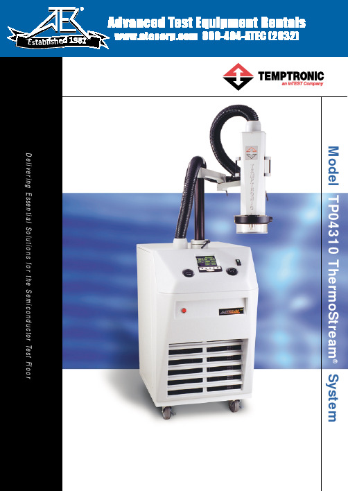
Mode 1: Manual Mode Operate the system at the touch of a button! For high throughput, pre-set HOT, AMBIENT and COLD temperature setpoints and soak times. With high capacity airflow and rapid temperature transition, the system quickly brings the DUT to temperature under Air or DUT Temperature Control Mode.
For moisture-free testing of standard to larger ICs, assemblies, PCBs, high frequency (RF to microwave) and high power devices at temperature, the TP04310 system and the ThermoFixture® thermal enclosure integrate seamlessly with any one of the major ATE testers for a turn-key thermal test system. ThermoFixture includes all tester interface hardware and electronics to ensure true and accurate signals in testing a DUT in a controlled thermal environment. (See ThermoFixture Brochure)
- 1、下载文档前请自行甄别文档内容的完整性,平台不提供额外的编辑、内容补充、找答案等附加服务。
- 2、"仅部分预览"的文档,不可在线预览部分如存在完整性等问题,可反馈申请退款(可完整预览的文档不适用该条件!)。
- 3、如文档侵犯您的权益,请联系客服反馈,我们会尽快为您处理(人工客服工作时间:9:00-18:30)。
Medeltest3.7:
准备工作:
下载modeltest软件windows版本,解压到系统盘,这里为C盘,我们这里将其置于根目录。
从/phylogenetics/modeltest.html该网站下载文件modelblockPAUPb10.txt和文件ML-search.txt。
下载Paup4.0
1.打开paup,打开你自己的filename.nex文件,然后再打开并执行所下载的modelblockPAUPb10.txt文件。
Paup将运行并产生一个名为model.scores的文件。
2.将产生的model.scores文件与modeltest执行程序放置在相同的文件夹内,这里为C:\modeltest3.7\Modeltest3.7 folder\bin\modeltest3.7.win。
3.在开始-运行中输入cmd命令,确认,弹出一个dos界面的窗口,将其默认目录改为model.scores文件所在文件夹,修改方式为在dos窗口输入:cd 盘符:\filename\filename,确认,这里我们输入
cd C:\modeltest3.7\” Modeltest3.7 folder” \bin\。
带有空格的文件夹名要用双引号括起来。
4.修改好后,在窗口内输入:Modeltest3.7.win.exe < model.scores > test.outfile,确认。
在model.scores 所在文件夹内产生test.outfile文件,即我们所需要的文件。
文件test.outfile的文件名可以修改。
5.用记事本打开test.outfile文件,里面列出了两种检验标准LRT和AIC分别选出的最优DNA进化模型。
6.如果你要在paup中利用最大似然法建树,那么只需将其中一种标准的对应命令拷贝到下载的ML-serch.txt文件中标记的位置,然后用paup打开你的nex文件之后执行该文件即可。
或者将命令拷贝到你自己的ML批处理文件内执行。
命令既是begin paup;和end;之间的部分。
7.如果是用于mrbayes分析,不能直接拷贝上述命令。
其中base即Base frequencies,代表各碱基出现的频率,顺序为A-C-G-T,其中T的频率没有列出来,不过这些值都可以在test.outfile中找到。
在mrbayes中,对应于Statefreqpr选项,该选项默认状态为Dirichlet(1.0,1.0,1.0,1.0),依次为A-C-G-T的频率,即各碱基的出现频率相同。
在此需将该选项状态修改为fixed( ),括号中依次填入base中对应的值,中间逗号隔开,如Statefreqpr=fixed(0.1649,0.3340,0.3209,0.1801)。
其中各值相加为1,但在mrbayes中,各值范围不定,各选项的值可同时乘或除以某值,如100,1000等,只要比例不变。
如在此可修改为Statefreqpr=fixed(1649,3340,3209,1801)。
其中rmat即rate matrix,是碱基位点的变异频率或者说异质率(rate heterogeneity),共6个值,R(a) [A-C],R(b) [A-G],R(c) [A-T],R(d) [C-G],R(e) [C-T],R(f) [G-T]。
rmat命令中只列出前五个,最后一个R(f) [G-T]未列出,不过这些值都可以在test.outfile中找到。
在mrbayes中,该命令对应于revmatpr选项,该选项默认状态为Revmatpr=Dirichlet(1.0,1.0,1.0,1.0,1.0,1.0),括号中对应于rmat的各值,顺序不变,依次为[A-C],[A-G],[A-T],[C-G],[C-T],[G-T],各数值间用逗号隔开;在此,我们需将该选项状态修改为fixed,即recmatpr=fixed( ),括号中依次填入rmat中对应的各值,如revmatpr=fixed(1.0000,3.7410,1.0000,1.0000,2.0672,1.0000)。
其中pinvar即Proportion of invariable sites,是不变位点的比率或称among-site rate variation,在mrbayes 中对应于Pinvarpr选项,该命令默认为uniform状态,即pinvarpr = uniform(0,1),取0-1内的一个值,0-1也是该选项的有效范围,在此,我们将该选项修改为fixed固定值选项,即pinvarpr=fixed( ),括号内填入pinvar中对应的数值,如pinvarpr=fixed(0.3076)。
其中Shape即Gamma distribution shape parameter,确定伽马分布的形状参数α,在mrbayes中对应于Shapepr选项,该选项默认状态为α范围内的均一分布,shapepr = uniform(0, α) ,在此修改为shapepr =fixed(1.5422)。
现在假设原命令是:
lset Base=(0.1649 0.3340 0.3209) Nst=6 Rmat=(1.0000 3.7410 1.0000 1.0000 2.0672) Rates=gamma Shape=1.5422 Pinvar=0.3076;
修改后对应的mrbayes命令为:
Lset nst=6 rates=gamma;
Prset Statefreqpr=fixed(0.1649,0.3340,0.3209,0.1801)
revmatpr=fixed(1.0000,3.7410,1.0000,1.0000,2.0672,1.0000) shapepr =fixed(1.5422) pinvarpr=fixed(0.3076); 在statefreqpr和revmatpr中,fixed一般设置为dirichlet,不知道两者有没有明显的差别?
另,statefreqpr以及shapepr、pinvarpr参数在mrbayes中似乎没见别人用过,不晓得为何?。