BPW自动调整臂安装说明(2017-12)(1)(1)
2、(BPW)空气悬挂、盘式制动器和制动间隙自动调整臂

空气悬挂
空气悬挂使用误区
误区一
空气悬挂具有很好的减震性能,所以有的用户会产生误解,比如说道路 条件比较差,为了提高货物的保护,采用空气悬挂,结果货物保护了,悬 挂系统故障频发。实际上,这就好比奔驰S级轿车舒适性一流,但是在土路 和爬山的时候,悬架零件容易损坏,故障比较多,绝对不如奔驰G级。其实, 挂车的空气悬挂也是如此。
Weitergabe sowie Vervielfältigung dieser vertraulichen Unterlage(n), Verwertung und Mitteilung ihres Inhalts ist nicht ohne vorherige schriftliche Genehmigung gestattet. Zuwiderhandlungen verpflichten zu Schadenersatz. Alle Rechte für den Fall der Patenterteilung oder Gebrauchsmuster-Eintragung vorbehalten.
盘式制动器
盘式制动器的特点
货运汽车盘式制动器发展的过程基本上与轿车制动系统的发展过程 类似。早期轿车也是以鼓式制动器为主,后来随着公路条件的进步和改 善,开始在高级轿车上出现盘式制动器,当时的卖点就是盘式制动器制 动反应快,制动力上升迅速,制动间隙免调整。到现在轿车盘式制动器 使用非常普遍了。 挂车随着现代物流的发展,盘式制动器也开始大规模推广。 BPW是比较早推出盘式制动器车轴的企业,与奔驰卡车基本同时在市 场上开始销售。BPW盘式制动器规格齐全,性能稳定,在全球范围内有 广泛的应用。
Weitergabe sowie Vervielfältigung dieser vertraulichen Unterlage(n), Verwertung und Mitteilung ihres Inhalts ist nicht ohne vorherige schriftliche Genehmigung gestattet. Zuwiderhandlungen verpflichten zu Schadenersatz. Alle Rechte für den Fall der Patenterteilung oder Gebrauchsmuster-Eintragung vorbehalten.
Haldex刹车间隙自动调整臂的安装
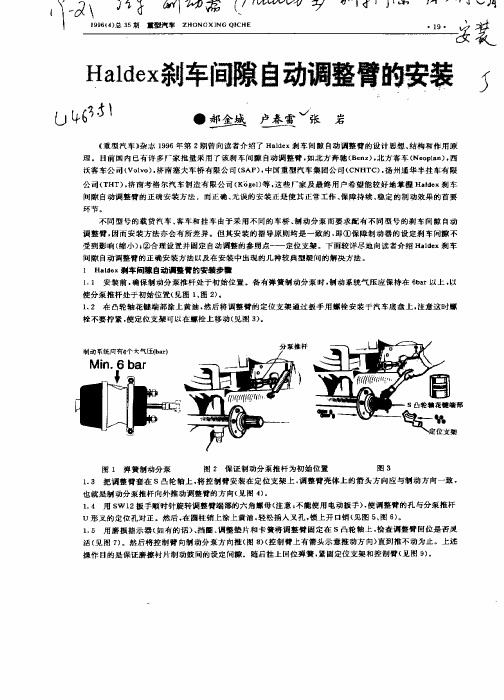
14 用 S 1 . W 2扳手顺 时 针旋转 调整 臂端部 的六 角螺 母 ( 注意 : 能使 用 电动扳手 ) 使调 整臂 的孔 与分 泵推 杆 不 ,
U形 叉的 定位孔 对正 。然后 , 在圆 柱销上 涂上黄 油 , 轻松插 入叉 孔 , 锁上 开 口销 ( 见图 5 图 6 。 、 )
( 本产 品巳在 国 内申请专 利 , 专利号 为 0 4 9 , ) 621 3 4 4
动效 果 非常满 意 . 明 Had x自动调 整臂 完全适 合 中国的道 路状 况和行 驶条 件 证 le
1 5 用 磨损 指 示器 ( . 如有 的话 ) 挡 圈 、 、 调整 垫 片和 卡 簧将 调 整臂 固定 在 S凸轮 轴 上 , 查调 整臂 回位 是否灵 检 活 ( 图 7 。然后 将控 制臂 向制 动分 泵方 向推 ( 8 ( 制臂 上有 箭头 示意 推动 方 向) 见 ) 图 )控 直到 推不 动为 止 。上述 操 作 目的是保证 磨擦 衬片制 动鼓 问的设 定 间豫 。随后挂 上 回位弹 簧 , 固定位 支架 和控制 臂 ( 图 9 。 紧 见 )
《 重型 汽 车 》 志 1 9 杂 9 6年 第 2期 曾 向读 者介 绍 了 Had x刹车 间 隙 自动调 整臂 的设 计 思想 、 构和 作用 原 le 结 理 。目前 国 内 已有 许 多厂家 批 量 采用 了该 刹 车 间豫 自动 调整 臂 . 北方 奔 驰 ( e z . 如 B n ) 北方 客 车 ( o ln . Ne pa ) 西
沃客车 公 司( ov ) 济南 塞夫 车桥 有 限公 司 ( AF) 中 国重 型 汽车 集团 公司 ( NHT ) 扬州 通华 半挂 车有 限 V lo , S , C C, 公 司 ( HT) 济 南考 格 尔汽 车 制造 有 限公 司 ( g 1等 . 些 厂家 及 最终 用户 希望 能 较好 地 掌握 Had x刹 车 T . K e) 这 le 间隙 自动调 整臂 的正 确安 装方 法 而正 确 、 无误 的安 装正 是使 其 正常 工作 、 障持 续 、 定 的制 动效果 的首 要 保 稳
BE SAFE Ranger 杠杆挽扳杆提升机说明书

NO RETURNS, CREDITS OR EXCHANGES FOR:
• Returned items that failed due to an accident, purchaser’s abuse, neglect or failure to operate in accordance with instructions provided in the owner’s manual(s) supplied.
• Returned items that are incomplete or defaced. • Any consumable or standard wear items. • Returned items with a different serial number from
what was authorized for return. • Returned items that do not include your original
BE SAFE Ranger™ Floor Jacks are designed and built with safety in mind. However, proper training and thoughtful operation on the part of the operator can increase your overall safety. DO NOT operate or repair this equipment without reading this manual and the important safety instructions shown inside.
自动化机械臂P5G系列夹紧器用户操作手册说明书

Automation ActuatorDivisionTABLE OF CONTENTS1. INSPECTION AND REPLACEMENT PROCEDURE FOR 30 DEGREE ANGULAR GRIPPER.(A) FOR PROX OPTIONS SEE SECTION 2C.2. INSPECTION AND REPLACEMENT PROCEDURE FOR 180 DEGREE ANGULARGRIPPER.(A) STROKE ADJUST FRONT.(B) STROKE ADJUST REAR.(C) PROXIMITY OPTIONS.3. INSPECTION AND REPLACEMENT PROCEDURE FOR PARALELL GRIPPER.(A) FUNCTION DRAWINGS.(B) STROKE ADJUST FRONT.(C) STROKE ADJUST REAR.(D) PROXIMITY OPTIONS.4. FASTENER TORQUE TABLES.DRAWING INDEXDRAWING 1: STANDARD 30 DEG ANGULAR GRIPPER.DRAWING 2: STANDARD 180 DEG ANGULAR GRIPPER.DRAWING 3: STANDARD 180 DEG ANGULAR GRIPPER, STROKE ADJUST FRONT.DRAWING 4: STANDARD 180 DEG ANGULAR GRIPPER, STROKE ADJUST REAR.DRAWING 5: STANDARD 30/180 DEG ANGULAR GRIPPER, PROXIMITY OPTIONS.DRAWING 6: STANDARD PARALELL GRIPPERDRAWING 7: STANDARD PARALELL GRIPPER, STROKE ADJUST FRONT.DRAWING 8: STANDARD PARALELL GRIPPER, STROKE ADJUST REAR.DRAWING 9: STANDARD PARALELL GRIPPER, PROXIMITY OPTIONS.NOTE: THIS MANUAL COVERS BASIC GRIPPER CONFIGURATIONS ONLY. SPRING ASSIST AND SPRING RETURN OPTIONS ARE NON USER SERVICEABLE. RETURN SPRING ASSIST AND SPRING RETURN OPTION GRIPPERS TO FACTORY FOR DISPOSITION ANDMAINTENANCE.Automation ActuatorDivision30 Degree Angular Gripper1.GENERALGrippers are position sensors ready with magnetic pistons. Each size uses a standardized sensor groove to accept Hall Effect, reed or proximity sensors. Optional Prestolock flowcontrol fittings provide smooth and controlled jaw action. For high temperature service,fluorocarbon seals are available.2.SPECIFICATIONSq Operating pressure range: 0.3 to 7 bar (4 to 100 psi)q Operating characteristics: double acting, single actingq Mounting orientation: unrestrictedq Working ports: M5q Operating temperature rangeq Standard seals –20 to 82 degree Celsius (-4 degrees to 180 degree Fahrenheit)q Fluorocarbon seals –20 to 121 degree Celsius (-4 degrees to 250 degree Fahrenheit) q Filtration requirement: 40 micron filtered, dry air3. SECTION 1: INSPECTION AND REPLACEMENT PROCEDURE FOR 30 DEGREEANGULAR GRIPPERDisassembly:• Remove retaining ring (29).• Remove endcap (26).• Remove screw (22).• Remove piston assembly (20) from housing (17).• Remove 4 bolts (61).• Remove as a unit the guides (60), fingers (59) piston rod assembly (73) and rod endcap assembly (13)(14) (15), set aside on clean surface.• Clean and check all parts for excessive wear, replace if needed.A ssembly:• Apply a light coating of Accrolube Teflon Impregnated Grease to the seal groove in the piston assembly(20) and to the piston seal (21).• Install the piston seal on the piston assembly with the lettering facing the magnet.• Apply a light coating of grease to the piston rod seal (13) and install the seal in the Delrin endcap (14), cupped side first.• Apply grease to the o-rings (15) and install them on the endcaps (14) (26).• Install bumper (19) over piston rod assembly.Automation ActuatorDivision• Apply a light coating of grease to the piston rod assembly (73) and insert it in the Delrin endcap with the rod seal towards the dowel end.• Attach the piston assembly (20) to the piston rod assembly (73) using permanent threadlocker on the screw (22) and tighten to the proper torque.• Insert the piston and the Delrin endcap in housing.• Apply a light coating of grease to the pivot point surfaces of the finger subassemblies (58) (59).• Apply a heavy coating of grease to the pivot point holes in the guides (60). (Note: click here to go to the proximity sensor section if your gripper has that option).• Insert a dowel (16) chamfered end first, into one of the guides.• Slide the guide with the dowel, and the fingers onto the piston rod assembly.• Slide the other guide onto the other side.• Apply removable threadlocker to four SHCS (61).• Push the guides into place on the housing and secure with the four SHCSs (61).• When tightening the screws, hold the guides together with light pressure. Tighten the screws to the proper torque.• Insert the remaining endcap (29) into the housing (17) and secure with the retaining ring.Automation ActuatorDivisionDRAWING 1BALLOON DESCRIPTION QUANITY BALLOON DESCRIPTION QUANITY 13ROD SEAL122PISTON FASTENER1 14ROD END CAP124BUMPER1 15O-RING226END CAP1 16DOWEL PIN229RETAINING RING1 17HOUSING159FINGER2 19BUMPER160GUIDE2 20PISTON ASSEMBLY161GUIDE FASTENER4 21PISTON SEAL173PISTON ROD1ASSEMBLYAutomation ActuatorDivision180 Degree Angular Gripper1.GENERALGrippers are position sensors ready with magnetic pistons. Each size uses a standardized sensor groove to accept Hall Effect, reed or proximity sensors. Optional Prestolock flowcontrol fittings provide smooth and controlled jaw action. For high temperature service,fluorocarbon seals are available.2.SPECIFICATIONSq Operating pressure range: 0.3 to 7 bar (4 to 100 psi)q Operating characteristics: double acting, single actingq Mounting orientation: unrestrictedq Working ports: M5q Operating temperature rangeq Standard seals –20 to 82 degree Celsius (-4 degrees to 180 degree Fahrenheit)q Fluorocarbon seals –20 to 121 degree Celsius (-4 degrees to 250 degree Fahrenheit) q Filtration requirement: 40 micron filtered, dry air3. SECTION 2: INSPECTION AND REPLACEMENT PROCEDURE FOR 180 DEGREEANGULAR GRIPPERDisassembly:• Remove retaining ring (29).• Remove endcap (26).• Remove screw (22).• Remove piston assembly (84) from housing (17).• Remove 4 bolts (72).• Remove as a unit the guides (77), fingers (74), levers (76), piston rod assembly (78) and rod endcap assembly (13) (14) (15), set aside on clean surface.• Clean and check all parts for excessive wear, replace if needed.A ssembly:• Apply a light coating of Accrolube Teflon Impregnated Grease to the seal groove in the piston assembly(84), and to the piston seal (21).• Install the piston seal on the piston assembly with the lettering facing the magnet.• Apply a light coating of grease to the piston rod seal (13) and install the seal in the Delrin endcap (14).• Apply grease to the o-rings (15) and install them on the endcaps (14) (26).• Install bumper (19) over piston rod assembly.• Apply a light coating of grease to the piston rod assembly (78) and insert it in the Delrin endcap with the rod seal towards the dowel end.• Attach the piston assembly (84) to the piston rod assembly using permanent threadlocker on the screw(22) and tighten to the proper torque.Automation ActuatorDivision• Insert the piston and the Delrin endcap in housing.•Apply a light coating of grease to the pivot point surfaces of the finger/lever assemblies (74) (76).• Apply a heavy coating of grease to the pivot point holes in the guides (77).• Insert a dowel (16) chamfered end first, into one of the guides. (Note: click here to refer to the section on proximity sensors if it pertains to your gripper.)• Slide the guide with the dowel, the fingers and the levers onto the piston rod assembly.• Slide the other guide onto the other side. (Note: click here to refer to the section on stroke adjust front if it pertains to your gripper.)• Apply removable threadlocker to four SHCS (72).• Push the guides into place on the housing (17) and secure with the four SHCSs (72). When tightening the screws, hold the guides together with light pressure.• Tighten the screws to the proper torque. (Note: click here to refer to the section on stroke adjust rear if it pertains to your gripper.)• Insert the remaining endcap (26) into the housing and secure with the retaining ring (29).Automation ActuatorDivisionDRAWING 2BALLOON DESCRIPTION QUANITY BALLOON DESCRIPTION QUANITY 13ROD SEAL126END CAP1 14ROD END CAP129RETAINING RING1 15O-RING272FASTENERS4 16DOWEL PIN274FINGER2 17HOUSING175DOWEL2 19BUMPER176LEVER2 21PISTON SEAL177GUIDE2 22PISTON FASTENER178PISTON ROD ASSEMBLY1 24BUMPER184PISTON ASSEMBLY1Automation ActuatorDivisionSTROKE ADJUST FRONTDRAWING 3SECTION 2A: STROKE ADJUST FRONT• Install the stroke adjust cap (80) on top of the guides.• Apply removable threadlocker to the last 3-4 threads of fasteners (79) and tighten to proper torque.• Install set screw (83), flat washer (81) and jamnut (82) so that the piston has a full stroke. Tighten jam nut.Automation ActuatorDivisionSTROKE ADJUST REARDRAWING 4SECTION 2B: STROKE ADJUST REAR•Screw the peened set screw (33) fully into the end cap (28) so the peened end is in the counter bore.•Install the sealing washer (30), flat washer (31) and jam nut (32) on the outside of the setscrew.•Tighten the jam nut.•Apply a light coating of grease to the o-ring groove in the end cap and the o-ring(15). Install the o-ring on the end cap and insert into the housing. Install theretaining ring (29) into the housing.Automation ActuatorDivisionPROXIMITY SENSORDRAWING 5SECTION 2C: PROXIMITY SENSORS• Insert a dowel (*16) chamfered end first, into the guide containing the clearance holes for the finger pivot dowel.• Slide the guide with the dowel, (and the fingers with the longer end of the dowel protruding out of the guide), onto the piston rod assembly, and facing up towards the slots on the housing.• Slide the other guide onto the other side.• Apply removable threadlocker to four SHCS.• Push the guides into place on the housing and secure with the four SHCSs (*61). When tightening the screws, hold the guides together with light pressure.• Tighten the screws to the proper torque.• Insert the remaining endcap (*29) into the housing (*17) and secure with the retaining ring.• Attach both sensor flags (67) to the pivot pins (65A) of the fingers. Mount proximity sensors and bracket(71) with 1mm clearance between sensor and nearest flag surface.*SEE DRAWING 1 FOR 30 DEGREE GRIPPER*SEE DRAWING 2 FOR 180 DEGREE GRIPPERAutomation ActuatorDivisionParallel Gripper1.GENERALGrippers are position sensors ready with magnetic pistons. Each size uses a standardizedsensor groove to accept Hall Effect, reed or proximity sensors. Optional Prestolock flowcontrol fittings provide smooth and controlled jaw action. For high temperature service,fluorocarbon seals are available.2.SPECIFICATIONSq Operating pressure range: 0.3 to 7 bar (4 to 100 psi)q Operating characteristics: double acting, single acting, spring assistq Gripping force @ 6 Bar: 78 to 1086 N (17.5 to 244 lb.)q Mounting orientation: unrestrictedq Working ports: M5q Operating temperature rangeq Standard seals –20 to 82 degree Celsius (-4 degrees to 180 degree Fahrenheit)q Fluorocarbon seals –20 to 121 degree Celsius (-4 degrees to 250 degree Fahrenheit) q Filtration requirement: 40 micron filtered, dry air3. SECTION 3:INSPECTION AND REPLACEMENT PROCEDURE FOR PARALLEL GRIPPER Disassembly:• Remove retaining ring (29).• Remove endcap (26).• Remove screw (22).• Remove piston assembly (20) from housing (17).• Remove cover (1).• Remove 4 screws (3).• Remove as a unit the guide cap (4) guide (9), fingers (10), piston rod assembly (6) (7) (8) and rod endcap assembly (13) (14) (15), set aside on clean surface.• Clean and check all parts for excessive wear, replace if needed.A ssembly:• Apply a light coating of Accrolube Teflon Impregnated Grease to the seal groove in the piston assembly (20) and to the piston seal (21).• Install the piston seal on the piston assembly with the lettering facing the magnet. Set aside on a clean surface.Automation ActuatorDivision• Apply a light coating of grease to all surfaces of the fingers (10) except the face with the tapped holes.• Apply a heavy coating of grease in the finger slot. Set aside on a clean surface.• Press two dowels (16) chamfered end first, into guide (9) if the fit requires it.• Apply a light coating of grease to the inside channel surfaces of the guide and a heavy coating of grease in the slots of the guide.• Temporarily set the guide in position on top to the housing (17).• Apply a light coating of grease to all surfaces of the piston rod assembly (6) except the tapped end.• Install a bronze spacer (7) on each end of the piston rod assembly and slide against the piston rod.• Install the fingers on the piston rod assembly according to the function drawings.See function drawings in Section 3A.Apply a light coating of grease on each bearing (8) and install on the piston rod assembly.• Rotate the etched mark on the bearing so that the etched marks face opposite the tapped end of the piston rod.• Insert the piston rod assembly with fingers into the channel in the guide with the piston rod protruding through the floor of the guide (9). The etched marks on the bearing should be visible at the top of the guide track. If not, re-install.• Apply a light coating of grease to the o-ring grooves in the endcaps (14) (26) and the o-rings (15).• Install the o-rings on the endcaps (14) (26).• Insert the rod seal (13) into the pocket in the Delrin endcap (14), cupped side first. Set aside on a clean surface.• Remove the guide/finger assembly from the housing (17) and move the piston rod to maximum extension through the guide.• Install the Delrin endcap assembly over the piston rod assembly, seal end first, keeping grease clear of the tapped hole in the piston rod assembly.• Set guide/ finger assembly on a clean surface with the piston rod assembly up.• Set the piston assembly on top of the piston rod assembly, small counter bore to the rod.• Apply removable threadlocker to the last four threads of the screw (22) and tighten to proper torque.• Apply a light coating of grease to the bore of the housing (17).• Set housing on clean surface with bore vertical and two dowel holes up.• Install two dowels (16) in housing.• Insert guide/piston sub assembly into the housing.• Apply a light coating of grease to the flat side of the guide cap (4) keeping grease away from the holes.• Install the guide cap on top of the guide with the solid edge above the fingers.• Apply removable threadlocker to the last 3-4 threads of the four screws (3) and tighten per proper torque.• Apply a light coating of grease to the end cap (26) and the o-ring.Automation ActuatorDivision• Insert the endcap into the housing (17). Install the retaining ring (29) into the housing.• Install the cover (1) by stretching over the fingers.DRAWING 6BALLOON DESCRIPTION QUANITY BALLOON DESCRIPTION QUANITY 1COVER115O-RING23FASTENER416DOWEL PIN24GUIDE CAP117HOUSING1119BUMPER1 6PISTON RODASSEMBLY7SPACER220PISTON ASSEMBLY18BEARING221PISTON SEAL19GUIDE122PISTON FASTENER1Automation ActuatorDivision10FINGER224BUMPER1 13ROD SEAL126END CAP1 14ROD END CAP129RETAINING RING1 SECTION 3A: FUNCTION DRAWINGSF01 FINGER ARANGEMENTSTANDARD TRAVEL, MAXIMUM GRIP CLOSEDSAMPLE MODEL CODESP5G-AP4B AD NNSP5G-AP4B AE NNSP5G-AP4B AF NNSP5G-AP4B AG NNSP5G-AP4B AN NNS(MAN10.DWG)F01 FINGER ARANGEMENTSTANDARD TRAVEL, MAXIMUM GRIP OPENSAMPLE MODEL CODESP5G-AP4B BD NNSP5G-AP4B BE NNSP5G-AP4B BF NNSP5G-AP4B BG NNSP5G-AP4B BN NNS(MAN11.DWG)Automation ActuatorDivisionF03 FINGER ARANGEMENT EXTENDED TRAVEL, MAXIMUM GRIP OPENSAMPLE MODEL CODESP5G-AP4B DD NNSP5G-AP4B DE NNSP5G-AP4B DF NNSP5G-AP4B DG NNSP5G-AP4B DN NNS(MAN6.DWG)F02 FINGER ARANGEMENT EXTENDED TRAVEL, MAXIMUM GRIP CLOSEDSAMPLE MODEL CODESP5G-AP4B CD NNSP5G-AP4B CE NNSP5G-AP4B CF NNSP5G-AP4B CG NNSP5G-AP4B CN NNS(MAN9.DWG)Automation ActuatorDivisionDRAWING 7SECTION 3B: STROKE ADJUST FRONT•Install the stroke adjust guide cap (5) on top of the guide with the solid edge above the fingers.• Apply removable threadlocker to the last 3-4 threads of fasteners (3) and tighten to proper torque.• Cycle the gripper by hand. Should be smooth and easy to move. Install set screw (34), flat washer (31) and jam nut (32) so that the piston has a full stroke. Tighten jam nut.Automation ActuatorDivisionDRAWING 8SECTION 3C: STROKE ADJUST REAR• Screw the peened set screw (33) fully into the end cap (28) so the peened end is in the counter bore.• Install the sealing washer (30), flat washer (31) and jam nut (32) on the outside of the setscrew.• Tighten the jam nut.• Apply a light coating of grease to the o-ring groove in the end cap and the o-ring (15).• Install stroke adjust rear endcap (28) into housing and secure with retaining ring (29).•Install cover by stretching over fingers.Automation ActuatorDivisionDRAWING 9SECTION 3D: PROXIMITY OPTIONS• Attach both sensor flag brackets (48), to the gripper using the shipping screws (51) with flag screws (50)and jam nuts (49) installed as shown.• Mount proximity sensor bracket (45) to gripper housing as shown and secure with set screws (46).• Insert proximity sensors as shown with clearance between sensor and nearest flag surface equal toapproximately 1mm.• Secure sensors with set screws (47). Caution! Do not tighten to the extent that the sensor is damaged.• Cycle the gripper and (referring to the picture above) adjust the left hand screw so that the left hand sensor makes on the end of the screw when the gripper is closed.• Tighten jam nuts.• Cycle the gripper and (referring to the picture above) adjust the right hand screw so that the right hand sensor makes only on the screw head when the gripper is open.•Tighten jam nuts.PROXIMITY SENSOR SAMPLE MODEL CODES P5G-AP4AN PA S-*P5G-AP4AN PB S-*P5G-AP4AN PC S-*P5G-AP4AN PD S-*P5G-AP4AN PF S-*P5G-AP4AN PG S-*P5G-AP4AN PK S-*(MAN17.DWG)Automation ActuatorDivisionSECTION 4: FASTENER TORQUESFASTENER SIZE TORQUE LOCATION GRIPPERSIZElbf in Nm GUIDE/HOUSING3M3x0.5-23 SHCS15 1.74M4x0.7-30 SHCS36 4.15M4x0.7-35 SHCS40 4.56M5x0.8-37 SHCS657.3 PISTON/ROD3M3x0.5-10 SHCS20 2.264M4x0.7-8 SHCS40 4.52M4x0.7-8 HHCS40 4.525M5x0.8-12 SHCS758.47M5x0.8-12 HHCS758.476M6x1.0-12 SHCS12013.56M6x1.0-12 HHCS12013.56Automation ActuatorDivision。
哈威主动式液压站操作与维护手册

占美摇臂的调试与维护
占美摇臂的调试与维护摘要随着电视事业的快速发展和观众需求的日益提高,大型摇臂在各台的应用越来越多。
本文对占美摇臂的调试与维护进行了探讨。
关键词大型摇臂;平衡调整;电气调试;机械维护1 平衡调整。
安装摇臂,关键在于平衡调整1)摇臂三脚架及支撑云台的水平调整。
三脚架的水平调节比较简单,调整三脚架的腿长,观测水平仪使其水平。
摇臂支撑云台水平不必每次使用都进行调整,如确需调整摇臂云台水平,可松开云台上的2颗螺栓,调整云台水平;2)镜头聚焦和光圈驱动马达的调整。
安装聚焦和光圈驱动马达时,应把镜头聚焦和光圈环转到任意一方的尽头,才把齿轮扣上去,注意锁紧马达时,聚焦马达压上去时是有弹性的,应尽量压紧,然后把锁定钮锁紧。
但在调试前先不扣紧,这里关键是要使聚焦和光圈电机的行程(旋转方向和角度)与镜头聚焦和光圈环的行程相吻合。
如安装不当会发生:(1)镜头聚焦和光圈环已旋转到底,而驱动电机仍可转动,造成齿轮脱滑,不能控制,并容易损坏齿轮和电机;(2)电机旋转到末端,但聚焦和光圈环没有到位,无法实现聚焦和调节光圈;3)前臂电动云台的调整。
以电动云台水平和垂直转动轴分成2个部分分别调整。
(1)以水平转动轴为主的电动云台上臂的调整:①水平调整,摇臂臂杆安装好后,将摄像机安装在平台上,用水平尺测云台上臂的水平,调整接力平衡钢索与前平衡钢索的连接螺丝杆,使水平尺指示水平状态。
如没有水平尺,可找一参照物(与地面平行物)。
②垂直调整,将水平尺靠在云台上臂上,松开锁紧螺栓,左右转动云台上臂,使之垂直;也可观察云台上臂,使其无论转到哪个角度都能停住,保持动态平衡,这时旋紧锁定螺钉即可;(2)以垂直转动轴为主的摄像机安装平台的调整。
这部分调节需要装上摄像机、镜头聚焦伺服组件、电池、连接好所有电缆后进行。
①静态平衡调整,与一般三脚架云台一样,通过移动摄像机托板前后位置,使摄像机保持水平平衡,不低头、不仰头。
②动态平衡调整:松开云台上动态平衡锁,调整摄像机安装平台的上下位置,先轻轻锁紧动态平衡锁,垂直方向转动摄像机,直到摄像机在每个角度都不会前后倒,动态平衡就调好了;或将摄像机安装平台转动90°呈垂直状态,松开动态平衡锁,调整摄像机的前后位置,使其也能保持静止不动,旋紧旋钮。
泵车智能臂架操作手册(泵车)

泵车智能臂架操作手册三一重工泵送研究本院控制所2010年10月前言操作泵车智能臂架前请仔细阅读本说明书,并特别注意文中的粗体字。
使用范围:1.本说明书适用于三一重工混凝土泵车智能臂架系统的操作。
2.本说明书中所提到的智能臂架的所有功能,均可通过遥控器操作完成;相关泵车工况信息以及故障诊断信息,均可以在液晶显示屏上显示。
3.当泵车电控系统处于“近控状态”或紧停按钮被按下时,遥控器不起作用。
遥控系统中由操作手操作的部分在本文中被称为遥控发射器(简称遥控器),安装在泵车上的部分在本文中被称为遥控接收器(简称接收器)。
安全事项:1.使用遥控器操作时,为保证遥控系统的可靠工作,请勿将遥控器上的天线取下。
2.在进行臂架的各种操作时,请保证臂架的各部分完全处于操作手的可视范围内。
如果臂架不在操作手的可视范围内,请停止操作臂架。
3.当模式切换开关处于“直角”或“柱面”时,请特别注意各节臂架及臂架末端点的位置和运动方向,避免臂架和周围环境中的物体发生碰撞。
4.遥控器上的显示屏属于易损部件,手持遥控器时请注意背好背带。
遥控器面板说明俯视图:(图一)1:天线;2.电池欠压指示灯;3:液晶显示屏;4:定向/清零拨动开关 5:翻页/确认旋(按)钮;6:万向手柄;7:正/反泵开关;8:锁臂开关;9:自动展臂/收臂开关;10:模式切换开关;11:快/慢切换开关;12:启动按钮;13:排量增减拨动开关;14-17:1至4号臂双向手柄;31214-1745678910111213右侧视图:(图二)左侧视图:(图三)18:遥控器断电按钮;19:讯响按钮;20:紧停开关;21:上翻按钮;22:下翻按钮;23:遥控器智能钥匙;24:发动机熄火按钮25:遥控器显示屏程序下载接口;26:遥控器电板18 19 20 21 22 23 2425 26编码名称作用1 遥控发射器天线增强遥控器发射信号2 电池欠压指示灯指示遥控发射器电池电量,绿色为电量正常,红色表示电量不足,要更换电池3 液晶显示屏显示泵车工况,查询故障4 定向/清零拨动开关设定坐标系用,暂未开放5 翻页/确认旋(按)钮旋转用于显示屏翻页,按下表示确认选择6 万向手柄手动模式时控制5号臂架展臂/收臂,转台旋转;智能模式时控制臂架末端水平直走。
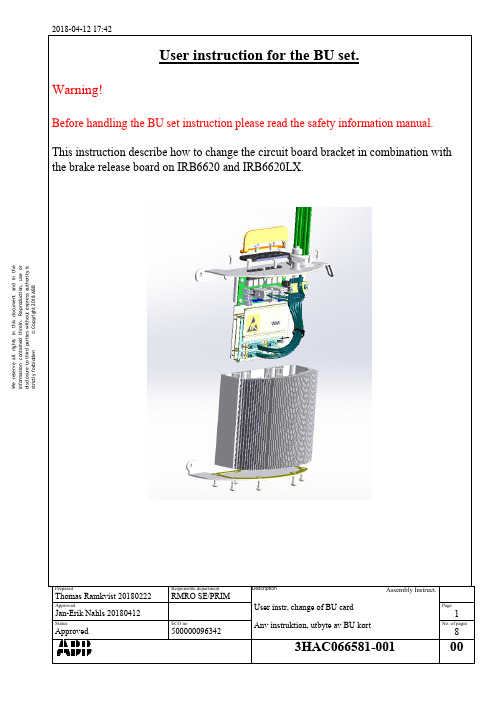
ABB IRB6620和IRB6620LX机械臂BU卡更换指南说明书
© Copyright 2018 ABB
disclosure to third parties without express authority is
information contained threin. Reproduction, use or
We reserve all rights in this document and in the
information contained threin. Reproduction, use or
We reserve all rights in this document and in the
strictly forbidden
Prepared
Thomas Ramkvist 20180222
Approved
© Copyright 2018 ABB
disclosure to third parties without express authority is
information contained threin. Reproduction, use or
We reserve all rights in this document and in the
Assembly Instruct.
User instr, change of BU card Anv instruktion, utbyte av BU kort
3HAC066581-001
Page
6
No. of pages
8
00
2018-04-12 17:42
Re-install the cables to the SMB unit with the new the screen grounding plate. (FIX THE CABLES IN THE SAME POSITION AS IT WAS FROM THE BEGINNING).