风机说明书(中英文)
风机参数(中英)
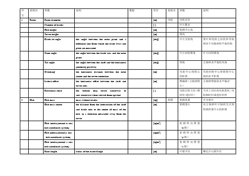
(海上适用)
Mean water depth (offshore only)
[m]
理论平均水深
(海上适用)
4
Tower foundation
Translational stiffness
horizontal
[N/m]
基础
平移刚度
水平
Foundation mass
[kg]
基础质量
Rotational stiffness
[kg/m]
密度
Material young’s modulus
[N/m]
杨氏模量
Tower eigenfrequency 1st bending downwind
[Hz]
塔架一阶频率(弯曲下风向纵向)
Tower eigenfrequency 1st bending lateral
[Hz]
塔架一阶频率(横向)
序号
系统名
参数
说明
数据
单位
系统名
参数
说明
1
Rotor
Rotor diameter
[m]
风轮
风轮直径
Number of blades
[-]
叶片数目
Hub height
[m]
轮毂中心高
Tower height
[m]
塔高
Blade set angle
the angle between the rotor plane and a reference line from which the blade twist and pitch are measured
[m]
侧偏移(主轴到塔心)
SFG21F-C5A一次风机使用说明书(英)
Instruction ManualProduct Type: SFG21F-C5A Primary Fan Product Code: T515Document No.: T515SYDelivery No.:Delivery Date:SHENYANG BLOWER VENTILATING CO.,LTDContents1.Fan Application2.Main Technical Parameter of Fan3.Performance Parameter4.Fan Performance Conversion5.Fan StructureRotor setJournal Bearing、Thrust BearingCasingInlet BoxSuctionDamperSuction、Discharge Companion Flanges6.Fan Installation7.Running of FanRunning-test of FanEmergent shut down and Steps8.Fan MaintenanceCaution of MaintenanceCaution of OperationFan Troubles and reasons9.Fan Overhaul9.1 Fan Disassembly Steps9.2 Main Overhaul Items10.Attached Drawing of Instruction1. Fan ApplicationSFG21F-C5A primary fan is Indonesia Pelabuhan ratu 3x350MW coal fired power plant, Inlet medium temperature is 37.8℃.2.Main Technical Parameter of Fan:2.1 Fan type: Centrifugal type with single suction and double-support2.2 Air inlet direction: 90°(right-hand rotating)2.3 Air outlet direction: 30°(right-hand rotating)2.4 Impeller diameter: 2050mm (at blade tip)2.5 Max. Circumference speed of impeller: 159m/s2.6 Rotor flywheel moment GD2: 4800kg-m22.7 Rotor set weight: 2343kg2.8 Total fan weight: 12000kg3.Performance parameter3.1 Design parameters:Total pressure Pa: 14800Inlet flow m3/S: 98.36Inlet temperature ℃: 37.8Medium density kg/m3: 1.119Fan total pressure inner efficiency %:85Fan rotating speed r/m: 1493Shaft power Kw: 1790Motor power Kw: 20003.2 Fan performance curve (see Page 14)4. Fan performance conversionIf medium density changes, fan performance converts as the following formula:Q1=Q2; P1/P2=ρj1/ρj2; N1/N2=ρj1/ρj2;Q1/Q2=n1/n2; P1/P2=(n1/n2)2; N1/N2=(n1/n2)3Air density changes with inlet temperature and atmosphere pressure, their relation is:ρ1/ρ2 = (Pj1/Pj2)×{(273+tj2)/(273+tji)}Q-Flow; P-Pressure; N-power; ρ-density; j-inlet5.Fan Structure:Fan is mainly consisting of rotor set、support bearing、thrust bearing、casing、air inlet box、air inlet suction、damper、suction and discharge companion flanges etc.5.1 Rotor SetRotor set、coupling、support bearing、thrust bearing、base-plate composea rotation system. Rotor set is made up of impellers and shafts, impeller ismade up of blade、wheel cover、main disc and hub. Ten backward airfoil blades are welded between curved wheel cover and plate main disc. Blade、wheel cover、main disc materials are all 15Mnv, impeller welding seam have passed dye penetrate test and been regulated by static and dynamic balance, so the operation shall be safe and stable. The advantages of the impeller is high efficiency、low noise、high intensity. Material of main shaft is No.45 steel.5.2 Journal bearing and thrust bearingRolling bearing has been adopted to journal bearing and thrust bearing.Bearing adopts oil lubrication and water-cooling for bearing box. Lube oil is GB11120-89 steam turbine oil, and brand No. N46. Bearing box uses lapping type oil throwing ring, aluminum bisect oil seal and asbestos packing. Oil level indicator is set on bearing box. For height of oil level, please see fan general diagram. Bearing cooling water sleeve is together within bearing box, when bearing temperature is high, it may cool by water, cooling water pressure is 0.2-0.3Mpa and flow is 2-3 t/h. Double-branch platinum thermal resistance used for measuring temperature of bearing and bi-metal thermometer have been installed on bearing box.5.3 CasingCasing is welded with steel plate Q235A, it is of split structure, equipped with a manhole door and drain, which is easier for maintenance.5.4 Inlet boxInlet box is welded with steel plate Q235A, and split structure, which is easier for maintenance. One side of which is connected with suction, and the other side is connected with damper. In order to increase stiffness of inlet box, supporting pipes have been welded in it.5.5 SuctionSuction is welded with steel plate Q235A, and split structure, which is easier for maintenance. One side of which is connected with casing, and the other side is connected with inlet box. In order to increase its stiffness, rib plates are welded along the circumference between two flanges.5.6 DamperThere are 6 blades in damper, it can get better regulating efficiency by regulating air inlet capacity through changing the opening of guide vane and changing the characteristics of fan. The requirement of running conditions may be satisfied by regulating electric actuator and the angle ofguide vane through transmission shaft.5.7 Companion flangesCompanion flanges are provided for easy installation, and the user may weld his connecting pipes onto the suction and discharge flanges separately.6. Fan InstallationBefore installation, foundation should be prepared according to the basic dimension sketch of fan and electric motor and keep enough space for secondary grouting. At the same time, required materials, tools and equipments should be prepared (Lifting weight of biggest fan parts is 2343 kg), on the other hand, the packed parts of fan should be checked, the parts in case of damage, should be repaired and replaced immediately.Impeller and main shaft should be checked more carefully, inner of bearing box should be cleaned with kerosene. Cooling water pipe should be cleaned up without any obstruction.In order to prevent rust and reduce disassembly difficulty, lubricating grease or machine oil should be coated on the connecting surface. The connection bolts should be tightened after position pin is in place.Tighten the anchor bolts temporarily for the installation of casing with anchor bolts, check casing and pipes inner carefully, and make sure that noforeign matters, such as tools are left inside.Installation Steps:(1)Place anchor bolts first, and then put lower casing in position.(2) Put the bearing baseplate and lower bearing in position, axial and horizontal leveling should be made with reference to the hole of bearing and deviation of which should be no more than 0. 10 mm/ m.(3)Put the assembled rotating parts (including impeller, main shaft, bearing,oil whip ring etc.) into the bearing baseplate.(4)Assemble the upper cover of bearing box, measure clearance between oilseal and oil whip disc according to the dimensions provided on the drawings of journal bearing and thrust bearing, and ensure that radial clearance of main shaft and oil seal is uniformly filled with asbestos packing, tighten side covers and oil seals on two ends, connect cooling water pipe and then fill bearing box with new lube oil.(5)When installing suction, axial and radial clearance between suction andimpeller should be adjusted according to required dimension on general drawing of fan in order to guarantee high efficiency of fan.(6)Put the upper casing in position and tighten bolts between suction andcasing.(7)Connect inlet box with suction.(8)Pay attention to direction of the damper during assembly。
kkk-ap风机的运行维护手册(中英文对照)8p

2.Descriptions简介9
2.1.Fluidic effect (1-stage)工作原理(单级)9
2.2.Fluidic effect (2-stage)工作原理(双级)9
2.3.Description of the fan风机(部件)简介9
Stator components静止件10
Fan壳体27
Impeller叶轮28
Servomotor伺服马达29
Main bearings主轴承29
Adjustment device调节装置30
4.4.Unscheduled stoppage非计划停机维护30
4.5.Wear data (ID/ FGD fan only)磨损数据(仅适用于引风机/增压风机)31
We must point out that these operating instructions cannot always cover every eventuality completely. Accordingly they do not free the operator from the usual responsibility when operating technical equipmentalso in respects of health, safety and environmental protection. It is assumed that the operation personnel has been instructed and knows how to run the plant.
Disassembly拆卸51
Assembly组装52
5.10.Main bearing (sleeve bearing)主轴承(滑动轴承)55
通用风机安装维护使用说明书第三版.中英文A4
上海通用风机股份有限公司通用风机安装维护使用说明书目录Content页次page 一、安装概述Summarize of installation (2)⒈风机安装场所P o s i t i o n (2)⒉风机安装空间要求D e m a n d s o f space (2)⒊各种安装方法及要求Methods and demands of installation (3)⒋吊装于天棚的场合Situation of loaded on the ceiling (5)二、基础B a s i c (5)⒈混凝土基础C o n c r e t e b e d r o c k (5)⒉减振元件S h a k e p r o o f e l e m e n t (6)⒊减振元件的使用Using of the shakeproof element (7)三、搬运T r a n s i t (7)⒈部件检查C h e c k t h e p a r t s (8)⒉吊装及搬运Hoi st and t ransi t (8)⒊保管S a f e k e e p i n g (8)四、安装方法M e t h o d s o f i n s t a l l a t i o n (9)⒈水平校正P l a n e e m e n d a t i o n (9)⒉轴承座的安装Installation of bearing house (10)⒊确认电机转向Notarized the motor direction (13)⒋带轮及胶带P u l l ey and V-bel t (13)⒌联轴器校正S haft joint emendation (13)⒍管道连接J o i n o f p i p e (14)⒎热风机的安装Installation of hot-air blower (14)五、试车C o m m i s s i o n i n g (15)⒈检查C h e c k i n g (15)⒉加油P u t o n s t e a m (15)⒊盘车J i g g e r (15)⒋送风系统A i r-f e e d i n g s ys t e m (16)⒌电气配件E l ect ri c fi t t i ngs (16)⒍启动S t a r t u p (16)⒎运行确认N o t a r i z e t h e r u n n i n g (17)六、保养与管理M a i n t e n a n c ea n d m a n a g e m e n t (18)⒈定期检查P e r i o d i c c h e c k (18)⒉日常检查D a i l y c h e c k (22)⒊轴承的保养和检查Maintenance and checking of bearing (23)⒋联轴器的保养和检查Maintenance and checking of shaft joint (26)⒌胶带及带轮的保养和检查Maintenance and checking of pulley and V-belt (26)七、安全须知S afet y caut i on (29)非常感谢您选用创新精良的“上树”牌风机!First, thanks for selecting our innovative and excellent fans with “上树” brand!正确的安装和维护关系到风机性能及使用寿命。
风机说明书(中英文)

8.1 入口空气过滤器 ....................................... 8-2 8.2 超压阀...................................................... 8-2 8.3 止回阀...................................................... 8-2 8.4 消音器...................................................... 8-2 8.5 真空和压力表........................................... 8-3 8.6 阻塞指示计 .............................................. 8-3 8.7 电机过载装置........................................... 8-3 8.8 安全防护罩 .............................................. 8-3
TECHNICAL QUALIFIED PERSONNEL Only this Personnel can carry out the more complex maintenance and repairs.
The allocated Personnel shall perform only the operations for which he is trained and qualified a that fall within his field of responsibility.
1 简介
1.1 铭牌标志含义........................................... 1-2
KKKA风机的运行维护手册中英文对照
Method of operation操作方法59
Installation devices组装设备59
Disassembly拆卸60
Assembly组装61
5.14.Cooling/sealing air system (ID fan only)冷却/密封空气系统(仅用于引风机)64
1.Operating data运行参数6
1.1.Pressure indications压力指示6
1.2.Operating conditions运行条件6
1.3.Limitations to operating data运行参数限制6
1.4.Performance graph性能曲线7
1.5.Starting torques and mass moment of inertia启动力矩和转动惯量8
Shaft (1-stage)主轴(单级)13
Shaft (2-stage)主轴(双级)13
Servomotor (1-stage)伺服马达(单级)13
2.3.13.Servomotor (2-stage)伺服马达(双级)13
Control head控制头13
Adjusting piston油缸13
Disassembly拆卸51
Assembly组装52
5.10.Main bearing (sleeve bearing)主轴承(滑动轴承)55
Disassembly拆卸55
Assembly组装56
5.11.Shaft seals轴封:57
Disassembly拆卸57
Assembly组装57
AXIFAN 管型风机系列产品说明书

CATALOG AX200 | JANUARY 2013WWW.TCF.COMMODEL TCTATCVA AXIFAN® Vaneaxial Fan, except that guide vanes are notprovided. This makes the TCTA more suitable for lower pres-sures and provides cost savings.Capabilities• Wheel diameters 12" to 60"• Airflow to 96,000 CFM• Static pressures to 5" w.g.• 37 unique diameters and hub-to-tip ratiosAXIFAN® WheelThe heart of the TCTA AXIFAN® fan lies in its wheel. Cast ofhigh strength aluminum alloy, the one-piece TCTA AXIFAN®wheel has been developed to maximize the highest efficiencypossible. Attention to detail in blade and hub design have cre-ated what is felt to be the most efficient and reliable axial fanon the market today. With the wide range of hub-to-tip ratiosavailable, there is a TCTA AXIFAN® to meet any air movementrequirement.Hub-To-Tip RatioThe multitude of TCTA AXIFAN®wheels evolves from ninebasic castings. Each casting is machined and cut to the properdiameter. By cutting the same model casting to one of severaldifferent diameters, different hub-to-tip ratios are created. Sinceeach hub ratio has slightly different pressure/efficiency charac-teristics, the freedom of having several wheels (different hubratios) for a set diameter provides the opportunity to maximizeefficiency at the required point of rating.HousingTCTA AXIFAN® housings are one-piece, heavy-gauge, hot-rolledsteel construction. Flanges on both the inlet and outlet are inte-grally rolled and punched for attachment to ductwork or acces-sories as necessary. The seam is continuously welded andground smooth to assure efficient airflow through the housing.Drive Isolated from AirstreamThe shaft and bearing assembly is mounted within the innercylinder to isolate these components from the high velocityairstream.The V-belt drive assembly is extended through a two-piece beltfairing. The belt fairing is an aerodynamically designed tube,designed to maximize fan efficiency, minimize air blockage andreduce noise generation.Additional InformationFor additional information on the TCTA and TCVA AXIFAN®tubeaxial and vaneaxial fans, refer to Twin City Fan & BlowerCatalog AX100.This catalog contains performance tables for Arrangement 9belt driven fans. For Arrangement 4 direct drive selections andadditional selections not shown, refer to the Twin City Fan &Blower Fan Selector Program.36 B 5Approximation of Hub-To-Tip RatioWhere:3 = 40%, 4 = 43%, 5 = 50%6 = 57%,7 = 66%DriveB = Belt Driven (Arr. 9)D = Direct Drive (Arr. 4)Fan Diameter (inches)~~~~~Model TCTA is available with UL/C UL 705 listing for electrical, File No.E158680.TCTA Arr. 9AXIFAN® WheelModel NomenclatureTUBEAXIAL F ANSTWIN CITY FAN - CATALOG AX2002PERFORMANCE DATAWheel Dia.: 12"Outlet Area: 0.807 ft2Tip Speed: 3.14 x RPMWheel Dia.: 15"Outlet Area: 1.253 ft2Tip Speed: 3.93 x RPMRegular type face = Class I Bold type face = Class II Maximum RPM: Class I = 3540 Class II = 4552TWIN CITY FAN - CATALOG AX2004Wheel Dia.: 18"Outlet Area: 1.799 ft 2 Tip Speed: 4.71 x RPMWheel Dia.: 21"Outlet Area: 2.448 ft 2Tip Speed: 5.50 x RPMRegular type face = Class I Bold type face = Class IIMaximum RPM: Class I = 2971 Class II = 4000 (Sizes 18B4 and 18B5)Class II = 3820 (Sizes 18B6 and 18B7)Regular type face = Class I Bold type face = Class IIMaximum RPM: Class I = 2546 Class II = 4000 (Size 21B4) Class II = 3709 (Size 21B5)Class II = 3738 (Size 21B6) Class II = 3274 (Size 21B7)PERFORMANCE DATAPERFORMANCE DATAWheel Dia.: 24"Outlet Area: 3.191 ft2Tip Speed: 6.28 x RPMClass II = 2971 (Size 24B6) Class II = 2865 (Size 24B7)Wheel Dia.: 28"Outlet Area: 4.353 ft2Tip Speed: 7.33 x RPMRegular type face = Class I Bold type face = Class II Maximum RPM: Class I = 1910 Class II = 2456TWIN CITY FAN - CATALOG AX2006Wheel Dia.: 32"Outlet Area: 5.672 ft 2Tip Speed: 8.38 x RPMWheel Dia.: 36"Outlet Area: 7.166 ft 2Tip Speed: 9.42 x RPMRegular type face = Class I Bold type face = Class IIMaximum RPM: Class I = 1671 Class II = 2396 (Size 32B4) Class II = 2234 (Size 32B5)Class II = 2149 (Sizes 32B6 and 32B7)Regular type face = Class I Bold type face = Class II Maximum RPM: Class I = 1485 Class II = 2314 (Size 36B4) Class II = 2176 (Size 36B5)Class II = 2052 (Size 36B6) Class II = 1987 (Size 36B7)PERFORMANCE DATAPERFORMANCE DATAWheel Dia.: 42"Outlet Area: 9.793 ft2Tip Speed: 11.00 x RPMRegular type face = Class I Bold type face = Class II Maximum RPM: Class I = 1273 Class II = 1805 (Size 42B4)Class II = 1684 (Size 42B5) Class II = 1637 (Size 42B6)Wheel Dia.: 48"Outlet Area: 12.77 ft2Tip Speed: 12.57 x RPMRegular type face = Class I Bold type face = Class II Maximum RPM: Class I = 1114 Class II = 1654 (Size 48B4)Class II = 1542 (Size 48B5)TWIN CITY FAN - CATALOG AX2008Wheel Dia.: 54"Outlet Area: 16.12 ft 2Tip Speed: 14.14 x RPMRegular type face = Class I Bold type face = Class IIMaximum RPM: Class I = 990 Class II = 1444 (Size 54B3)Class II = 1348 (Size 54B4)Wheel Dia.: 60"Outlet Area: 19.87 ft 2Tip Speed: 15.71 x RPMRegular type face = Class I Bold type face = Class II Maximum RPM: Class I = 891 Class II =1146PERFORMANCE DATAMOTORARR. 4 – VERTICAL ARR. 9 – VERTICALARR. 4 – HORIZONTAL ARR. 9 – HORIZONTALAIRFLOW AIRFLOWAIRFLOW AIRFLOWVDO/VDN VDIVUI/VUN VUOCDBAEGFHHORIZONTALMOTORLOCATIONS(VIEWED FROMFAN OUTLET)VDO= Vertical Down Floor Mounted With LegsVDN = Vertical Down Discharge Without LegsVDI= Vertical Down Ceiling Hung With LegsVUI= Vertical Up Floor Mounted With LegsVUN = Vertical Up Discharge Without LegsVUO= Vertical Up Ceiling Hung With LegsHORIZONTAL DISCHARGESHOR = Horizontal – No Clips or Legs HCH = Horizontal Ceiling Hung with Suspension Clips HBM = Horizontal Base Mounted with Support LegsVERTICAL DISCHARGESDIMENSIONS ARE NOT TO BE USED FOR CONSTRUCTION. CERTIFIED DRAWINGS AVAILABLE UPON REQUEST.AC13597B AC13793ADIMENSIONAL DATA10AIRFLOWCONE COMPANION VARIABLE INLET BELLFLANGE INLET VANEDIMENSIONS ARE NOT TO BE USED FOR CONSTRUCTION. CERTIFIED DRAWINGS AVAILABLE UPON REQUEST.AC13716M DIMENSIONAL DATATwin City FanTYPICAL SPECIFICATIONSFans shall be Model TCTA AXIFAN® Tubeaxial Fans as manufactured by Twin City Fan & Blower, Minneapolis, Minne-sota. Fans shall be Arrangement 9, V-belt driven with the wheel mounted on a separate shaft and bearings supported completely within an enclosed tube isolated from the high velocity airstream or Arrangement 4, with the propeller mounted directly on the motor shaft and with the propeller and motor assembly enclosed entirely within the fan casing. PERFORMANCE — Fans shall be tested in accordance with ANSI/AMCA Standard 210 (air performance) and 300 (sound performance) in an AMCA accredited laboratory.Model TCTA shall be available UL 705 listed. Fans shall bear a permanently attached nameplate displaying model and serial number of the unit for future identification.HOUSING — Fan housings shall be welded of 14-gauge ASTM A-569 hot rolled steel on size 12, 12-gauge hot rolled steel on sizes 15 through 21, 10-gauge hot rolled steel on sizes 24 through 36, and 7-gauge hot rolled steel on sizes42 through 60. Inlet and outlet flanges are standard.WHEEL — The fan wheel shall be a solid one-piece sand casting of 319 alloy aluminum and shall contain seven blades and an integral center hub. The wheel shall have blades of airfoil shape designed with a variable hub ratio system to allow the selected fan to operate at the highest efficiency possible. Wheels shall be machined to the proper diameterso that blade tip clearance shall be within tolerance necessary to insure certified fan performance. The wheel shall be secured to the fan/motor shaft with a Trantorque® or taperlock bushing.SHAFT (ARR. 9) — Shafts shall be AISI 1040 or 1045 hot rolled steel, accurately turned, ground, polished, and ring gauged for accuracy. Shafts shall be sized for the first critical speed of at least 1.43 times the maximum speed. BEARINGS (ARR. 9) — Bearings shall be heavy duty, grease lubricated, anti-friction ball or roller, self-aligning, pillow block type and selected for a minimum average bearing life (AFBMA L-50) in excess of 200,000 hours at the maximum fan RPM. All bearings are provided with pre-filled factory extended lubrication lines terminating at the housing exterior. DRIVE (ARR. 9) — The fan shall be equipped with a (fixed/adjustable) pitch V-belt drive selected to operate the fan at the correct operational RPM. The V-belt drive shall consist of cast iron sheaves and anti-static conducting belts and shallbe selected with a (1.2/1.5) safety factor based upon the required brake horsepower of the fan.The complete fan shaft and bearing assembly is mounted within a steel fabricated inner cylinder. The V-belt drive as-sembly is extended through a two-piece belt fairing. The belt fairing shall be an aerodynamically shaped tube designedto maximize fan efficiency. The belt fairing is welded continuously to both the inner cylinder that houses the fan shaft and bearings and the fan housing.MOTOR — Motors for Arrangement 9 fans shall be manufactured in accordance with current applicable standards. Mo-tors shall be foot-mounted, NEMA standard (ODP, TEFC, Explosion-Proof), continuous duty, ball bearing type with class (B, F) insulation and of cast iron construction when commercially available.Motors for Arrangement 4 fans shall be foot-mounted, NEMA standard, totally enclosed fan cooled (TEFC), continuous duty, ball bearing type with class “F” insulation and of cast iron construction when commercially available. For easein wiring the motor, wiring connections shall be extended to an exterior conduit box located on the exterior of the fan housing. A duplicate motor nameplate shall be mounted on the exterior of the fan adjacent to the fan nameplate. External grease fittings with pre-filled factory extended grease leads shall be supplied for lubrication of the motor bearings on all motors that provide grease fittings.FINISH — The entire fan assembly, excluding the shaft, shall be thoroughly degreased and deburred before application ofa rust-preventative primer. After the fan is completely assembled, a finish coat of paint shall be applied to the entire as-sembly. The fan shaft shall be coated with a petroleum-based rust protectant. Aluminum components shall be unpainted. FACTORY RUN TEST — All fans with motors and drives mounted by Twin City Fan & Blower shall be completely as-sembled and test run as a unit at the specified operating speed prior to shipment. Each wheel shall be statically and dynamically balanced in accordance with ANSI/AMCA 204-96 “Balance Quality and Vibration Levels for Fans” to Fan Application Category BV-3, Balance Quality Grade G6.3. Balance readings shall be taken by electronic type equipmentin the axial, vertical, and horizontal directions on each of the bearings. Records shall be maintained and a written copy shall be available upon request.GUARANTEE — The manufacturer shall guarantee the workmanship and materials for its TCTA AXIFAN® tubeaxial fansat least one (1) year from startup or eighteen (18) months from shipment, whichever occurs first.TWIN CITY FAN & BLOWER WWW.TCF .COM5959 TRENTON LANE N | MINNEAPOLIS, MN 55442 | PHONE: 763-551-7600 | FAX: 763-551-7601CENTRIFUGAL FANS | UTILITY SETS | PLENUM & PLUG FANS | INLINE CENTRIFUGAL FANSMIXED FLOW FANS | TUBEAXIAL & VANEAXIAL FANS | PROPELLER WALL FANS | PROPELLER ROOF VENTILA TORS CENTRIFUGAL ROOF & WALL EXHAUSTERS | CEILING VENTILA TORS | GRAVITY VENTILA TORS | DUCT BLOWERS RADIAL BLADED FANS | RADIAL TIP FANS | HIGH EFFICIENCY INDUSTRIAL FANS | PRESSURE BLOWERS LABORA TORY EXHAUST FANS | FILTERED SUPPL Y FANS | MANCOOLERS | FIBERGLASS FANS | CUSTOM FANSINDUSTRIAL PROCESS ANDCOMMERCIAL VENTILATION SYSTEMS ©2018 Twin City Fan Companies, Ltd., Minneapolis, MN. All rights reserved. Catalog illustrations cover the general appearance of Twin City Fan & Blower products at the time of publication and we reserve the right to make changes in design and construction at any time without notice.Twin City FanTwin City Fan。
4-72-8c离心式通风机使用说明书中英文对照

4-72-8C离心式通风机使用说明书4-72-8C Centrifugal FanInstruction河南固德重型机器制造有限公司HENAN GUDE HEA VY MACHINERY MANUFACTURING COMPANG LTD地址:郑州市郑上路196号Add:No.196 Zhengshang Road,Zhengzhou,China电话(Tel):0086-371-68185666传真(Fax):0086-371-68183666邮箱(Email):*****************一.用途4-72-8c型离心通风机主要用途是为—般工厂及大型建筑物的室内通风换气或输送空气及其它不自燃、不易爆、不挥发、对人体无害、对钢材无腐蚀性之气体。
4-72-8c离心通风机输送的气体均不得含粘性物质,所含尘土及硬质颗粒物不大于150mg/m3,气体温度不得超80℃。
ageThe main use of 4-72-8c type centrifugal fan is for indoor ventilation as factories and large buildings or the air transport and other spontaneous which is not explosive, volatile, on harmful to the human body, no corrosion to steel.The delivery gas by 4-72-8c centrifugal fan shall not contain viscous substances, dust and hard particles containing is no more than 150mg / m3, the temperature of the gas shall not exceed80 ℃二.型式从电机—端正视,凡叶轮按顺时针方向旋转者均称“右旋风机”,以“右”表示,反之则均称之为“左旋风机”以“左”表示。
- 1、下载文档前请自行甄别文档内容的完整性,平台不提供额外的编辑、内容补充、找答案等附加服务。
- 2、"仅部分预览"的文档,不可在线预览部分如存在完整性等问题,可反馈申请退款(可完整预览的文档不适用该条件!)。
- 3、如文档侵犯您的权益,请联系客服反馈,我们会尽快为您处理(人工客服工作时间:9:00-18:30)。
8.1 入口空气过滤器 ....................................... 8-2 8.2 超压阀...................................................... 8-2 8.3 止回阀...................................................... 8-2 8.4 消音器...................................................... 8-2 8.5 真空和压力表........................................... 8-3 8.6 阻塞指示计 .............................................. 8-3 8.7 电机过载装置........................................... 8-3 8.8 安全防护罩 .............................................. 8-3
0-2
目录
I
INDEX
0 注意事项
0.1 声明 ........................................................0-1 0.2 机器相关警告标记...................................0-1 0.3 安全事项 .................................................0-2 0.4 操作人员 .................................................0-2
TECHNICAL QUALIFIED PERSONNEL Only this Personnel can carry out the more complex maintenance and repairs.
The allocated Personnel shall perform only the operations for which he is trained and qualified a that fall within his field of responsibility.
罗茨风机安装、使用及日常维护手册
INSTRUCTION MANUAL Installation, Use and Ordinary Maintenance
ROTARY BLOWER
石家庄博纳风机技术有限公司
BORA blower technology co., ltd
Email:borablowers@ Rev 1.0 04/2011
4 安装
4.1 基础传动调整.............................................. 4-2 4.2 管道 ............................................................ 4-2 4.3 启动前注意事项 .......................................... 4-2 4.4 风机固定 ..................................................... 4-3 4.5 风机出口连接............................................. 4-4 4.6 风机皮带张力调整 ..................................... 4-5
WARNINGS
Signal the risk of damage, possibly considerable, to the compressor
0-1
注意事项
0
WARNINGS
0.3 安全事项
当使用风机时,必须注意机器转动部位(直线或 旋转运动)可能对人和物体造成严重危害。
操作工必须注意: • 依靠风机使用说明。 • 避免风机用于任何不适当的用途。 • 避免去除或改变安全装置。 • 对风机进行定期维护。 • 使用原装配件。
is readily available • that the manual has been read very carefully and
that all the manufacturer’s recommendations and instructions contained there in are observed, • that only properly trained personnel is responsible for the use and ordinary maintenance of the compressor.
erations • use exclusively original parts
最后注意: • 原始说明的用途和维护目录可以参考。 • 设备制造商或集成商应详细阅读手册,并以此为依
据进行安装、说明。 • 风机应该由进行过专业培训的人员进行维护。
To this end it is essential that: • the original use and ordinary maintenance menu
1 简介
1.1 铭牌标志含义........................................... 1-2
2 技术特征
2.1 机器概述 .................................................. 2-2
3 储存和装卸
3.1 储存 ......................................................... 3-3 3.2 装卸 ......................................................... 3-3
0.4 操作人员
对风机进行操作的两类人员要求如下:
操作工 操作工不需要有太高的技术知识,但必须经过培
训,对于风机有通常的了解,如:启动、停止机器, 和基本的保养操作(如清洁)。
专业技术人员 只有这类人员可对风机进行比较复杂的维护和维
修。
相关人员只能在他进行培训和指定的职责范围进 行操作。
0.4 Operating personnel
5 风机运行
5.1 驱动方式 .................................................. 5-2 5.2 转向和气体流向 ....................................... 5-2 5.3 关于三角带连接 ....................................... 5-3 5.4 运转 ......................................................... 5-3
The personnel qualified to the use of the compressor can be divided in two categories according to the degree of training and responsibility, i.e.:
OPERATOR The operator does not need to be a highly technically knowledgeable person, but must be trained for ordinary use of the compressor i.e.: starting, stopping at the end of work, and in basic maintenance operations (cleaning)
关于说明书的理解不详之处,请与我们的服务工 程师联系。
The purpose of the Manual is to give the operating and technical qualified personnel useful instructions for the safe starting procedure, the use and the ordinary maintenance of the compressor. In case of doubts or lack of information, please contact our Service engineer.
6 故障处理
6.1 故障解答 .................................................. 6-2
7 维护
7.1 润滑油...................................................... 7-2 7.2 风机清洁 .................................................. 7-3 7.3 过滤器维护 .............................................. 7-3 7.4 传动 ......................................................... 7-3
9 最重要的维护点
9.1 维护表......................................................... 8-2 9.2 清洁 ............................................................ 8-2 9.3 清洁滤芯 ..................................................... 8-2 9.4 滤芯堵塞控制.............................................. 8-2