风力发电电力系统中英文对照外文翻译文献
毕业设计风力发电外文文献
Abstract--The purpose of this paper is to find an innovative, high efficiency, practical and low cost control system structure with an optimized control strategy for small-scale grid-connected wind turbine with direct-driven permanent magnet synchronous generator (PMSG). This research adopts the sensorless vector control strategy based on phase-locked loop (PLL) for PMSG control, and the grid-side inverter control strategy is based on the single-phase PLL. The simulation demonstrates that the sensorless control strategy and single-phase grid-side inverter control strategy are practical solutions for grid-connected PMSG wind turbines, and they can provide both generator speed control for optimized wind power tracking and good power quality control for electricity delivered to the grid. The designed system offers many unique advantages, including simple topology, optimized control strategy, cost-effective and fast respond to grid failures.Index Terms--Maximum power point tracking (MPPT), PMSG, pulse-width modulation (PWM) converter, speed control, variable-speed wind turbine.I. I NTRODUCTIONn recent years, great attention has been paid on renewable energy sources, such as wind and solar energy. Wind energy is the most popular renewable energy source due to its relatively low cost. The overall system cost can be further reduced by optimal control of high efficiency power electronic converters to extract maximum power in accordance with atmospheric conditions [11].The wind energy conversion system based on permanent magnet synchronous generator (PMSG) is one of the most favorable and reliable methods of power generation. Reliability of variable-speed direct-driven PMSG wind turbines can be improved significantly comparing to doubly-fed induction generator (DFIG) wind turbines with gearboxes. Noise, power loss, additional cost, and potential mechanical failure are typical problems for a DFIG wind turbine because of the existence of a gearbox. The use of direct-driven PMSG could solve these problems. Moreover, low voltage ride through (LVRT) is also a big issue for DFIG because the This work was supported in part by the special funds from Beijing Municipal Education Commission.Chunxue Wen, Guojie Lu, Peng Wang and Zhengxi Li are with the Power Electronics and Motor Drivers Engineering Research Centre, North China University of Technology,Beijing,China(e-mail: wenchx1980@, lugod307@, catdapeng2008@, lzx@).Xiongwei Liu and Zaiming Fan are with the School of Computing, Engineering and Physical Sciences, University of Central Lancashire, Preston, PR1 2HE, UK (e-mail: xliu9@, zmfan@) electromagnetic relationship between the stator and the rotor is more complex than PMSG. Therefore, it’s more difficult for DFIG to solve LVRT problem safely and reliably.In a variable-speed PMSG system, vector control approach is often used to achieve nearly decoupled active and reactive power control on the grid-side inverter which is a current regulated voltage source inverter. In this way, the power converter maintains the DC-link voltage and improves the power factor of the system [1], [7], [10]. Different control methods for maximum power point tracking (MPPT) in variable-speed wind turbine generators have been discussed in [2], [4], [7].This research adopts the sensorless vector control strategy based on phase-locked loop (PLL) for PMSG control [2]. The method requires only one active switching device, i.e. insulated-gate bipolar transistor (IGBT), which is used to control the generator torque and speed so as to extract maximum wind power. It is a simple topology and low cost solution for a small-scale wind turbine because of the sensorless vector control strategy. The grid-side inverter control strategy is based on the single-phase PLL, which applies a control method in Direct-Quadrature (DQ) rotating frame to single-phase inverter and achieves superior steady state and dynamic performance [6].For small-scale wind turbine, single-phase power supply to consumers is popular. There are many control methods for single-phase inverter, such as PI controller, quasi-PR controller, etc. [5]. However, these methods can’t decouple the active power and reactive power so as to have good power control performance. Single-phase PLL method based on DQ rotating frame can well solve this problem. On the other hand, encoders are vulnerable components for wind turbines, particularly for small wind turbines, because small wind turbines experience severer vibrations than their large counterparts. The sensorless vector control opts out the encoders, and therefore the reliability of wind turbines is much improved. For these reasons, the sensorless vector control and single-phase PLL method have their unique advantages for small-scale wind turbines.This paper is structured further in following three sections. In section II, the principle of the full power back-to-back PWM converter is introduced. Then the vector control of small-scale grid-connected wind power system including sensorless control, vector control of PMSG, single-phase PLL, vector control of grid-side inverter are described in section III. Finally, in section IV, the simulation results and conclusion are given.Vector control strategy for small-scale grid-connected PMSG wind turbine converter Chunxue Wen, Guojie Lu, Peng Wang, Zhengxi Li Member IEEE, Xiongwei Liu Member IEEE,Zaiming Fan Student Member IEEEIII. T HE PRINCIPLE OF FULL POWER BACK-TO-BACK PWMCONVERTERTypical topology model of direct-driven PMSG wind turbine is shown in Fig. 1. Converters of the system adopt back-to-back pairs of pulse-width modulation (PWM) architecture. The generator-side converter controls the generator speed in order to achieve maximum capture of wind power, and the grid-side inverter controls the stability of DC-bus voltage and the power factor of the system. This topology can be a good way to improve performance, and the control method is flexible. Converters have four-quadrant operation function, which can fulfill the generator speed control anddeliver the fine quality of electricity to the grid [7], [8].Fig. 1. Topology of permanent magnet direct-driven wind power systemIII. T HE VECTOR CONTROL OF SMALL-SCALE GRID-CONNECTEDDIRECT-DRIVEN WIND POWER SYSTEM CONVERTERFig. 2 shows the back-to-back PWM voltage convertervector control block diagram. The machine-side PWMconverter controls the electromagnetic torque and statorreactive power (reactive power is often be set to 0) byadjusting the current of the d-axis and q-axis of the machine-side converter. This control mechanism helps the PMSG tooperate in variable speed, so that the wind turbine can workwith maximum power point tracking (MPPT) under the ratedwind speed. The grid-side PWM inverter stabilizes the DC-busvoltage and accomplishes active and reactive decouplingcontrol by adjusting the current of the d-axis and q-axis of thegrid-side. The grid-side PWM inverter also controls thereactive power flow to the grid, usually at unity power factorcondition.A. Sensorless control based on PLLThe speed and position control is achieved throughsensorless vector control of the machine-side converter basedon all-digital phase-locked loop. The phase-locked loop isdesigned to control the frequency of the D-Q axis voltagethrough minimizing the difference of the output voltage phaseangle and the given voltage phase angle, until the outputvoltage phase angle tracks the given voltage phase angle. Asthe phase-locked loop has frequency closed-loop trackingmechanism, the generator voltage frequency and the anglebetween d-axis voltage and rotor flux can be measured withthis characteristic, then the generator speed and rotor positionangle can be derived [2]. The control accuracy is generallygood using this method, however some problems may occurwhen the generator operates at very low speed. The windpower system often works above the cut-in wind speed, so thismethod can be applied to wind power generation system.Fig. 2.The back-to-back PWM voltage converter vector control block diagramThe actual rotor position of PMSG is indicated in the D-Q coordinate system. The estimated location for ∧θ is the d q ∧∧− coordinate system, αβ is the stationary coordinate system, as shown in Fig. 3. As the rotor position of PMSG is estimated rather than measured in the sensorless vector control system, there exists an error θΔ between the actual rotor position θ and the estimated location ∧θ. At the same time, the back-EMF (electromotive force) generated by the rotor permanent magnets generates two d-axis and q-axis components in the estimated rotor position orientation coordinates, which are expressed as sd e ∧and sq e ∧respectively. Conventional PI controller can achieve zero error control, i.e. sd e ∧or θΔ can be adjusted to zero value. The PLL sensorless vector control schematic diagram is shown in Fig. 4, and the value of sd e ∧and sq e ∧can be obtained from (1).sd sd s sd dq sq sd sq sq s sq q d sd sq di u R i L L i e dt di u R i L L i e dt ωω∧∧∧∧∧∧⎧=+−−⎪⎪⎨⎪=+++⎪⎩(1)Fig. 3. Presumed rotating coordinate systemFig. 4. Principle of PLL based sensorless vector controlIf we ignore the current differential items in (1), then wehavesd s sd q sq sd sq sq s sq d sd ˆˆˆˆˆarctan(arctan(ˆˆˆˆˆu R i L i ee uR i L i ωθω−+Δ=−=−−− (2)where sd u , sq u , sd i and sq i are the d, q-axis components of the output voltage and current of the generator stator; d L q L and s R are the inductance and resistance of the stator; ω is thegenerator electrical angular velocity of the generator; "∧" indicates estimated value.Block diagram of sensorless vector control based on digital PLL is shown in Fig. 5. The back-EMF (electromotive force) value of the estimated rotating coordinates can be obtained by calculating the three-phase voltages and currents of the PMSGstator. The calculated angle difference θΔcan be used to estimate the angular velocity through the PI controller. Then the value of the estimated angle can be obtained by integral element. Generally, the speed has considerable fluctuations using this method. Therefore it will achieve a better estimation by adding a low-pass filter (LPF), as shown in Fig. 5.∧Fig. 5. Block diagram of sensorless vector control based on digital PLLB. Vector control of PMSGIn order to study the torque control of PMSG, it is necessary to establish a mathematical model. Because q-axis leads d-axis 90° in the D-Q coordinate system, the generator voltage equation can be expressed as [8]: sd sd s sd d sq sq sq sq sq q d sd di u R i L L i dt di u Ri L L i dt ωωωψ⎧=+−⎪⎪⎨⎪=+++⎪⎩(3) The significance of various physical quantities in (3) is the same as in (1).The generator electromagnetic torque equation can be expressed as:33()22e sq d q sd sq T p i p L L i i ψ=+− (4) where p is the number of generator pole pairs, and ψ is the magnetic flux.Based on the above mathematical model, the sensorless vector control program of PMSG is established, and its controlblock diagram is shown in Fig. 6.sa i sbi Fig. 6. Sensorless vector control block diagram of PMSGGenerator rotor position and speed which are estimated by sensorless algorithm can be used in vector control. Thereference value of motor torque can be obtained by the speedcontroller. The voltage reference of generator can also be gotby current controller, and then the control signals of rectifier switching device can be obtained by a set of PWM modulation algorithms. The position and speed of generator rotor which is necessary to vector control is obtained by sensorless algorithm.C. Single-phase grid-connected PLLFig. 7 shows the block diagram of the single-phase gird-connected PLL. In order to ensure that the converter outputvoltage is in the same phase with the output current, the PLLis used to achieve unity power factor control. At the sametime, the converter also provides the angle of the referencecurrent transformation [5].Fig. 7. The block diagram of the single-phase PLLThe transformation between orthogonal a-b and D-Q reference frames can be described by trigonometric relations, which are given in (5) and (6), and the rotating reference frame is shown in Fig. 8.Fig. 8. Definition of rotating reference frame⎥⎦⎤⎢⎣⎡⎥⎦⎤⎢⎣⎡−=⎥⎦⎤⎢⎣⎡b a q d f f f f θθθθcos sin sin cos (5) ⎥⎦⎤⎢⎣⎡⎥⎦⎤⎢⎣⎡−=⎥⎦⎤⎢⎣⎡q d b a f f f f θθθθcos sin sin cos (6)Active power and reactive power equations can beexpressed as:⎩⎨⎧−=+=d q q d qq d d i v i v Q i v i v P (7) If the phase voltage and q-axis coincide, then 0=d v andv v q =, active power and reactive power equations can besimplified as:||||q dP v i Q v i =⎧⎪⎨=−⎪⎩ (8) D. The vector control strategy of the grid-side inverterFor a three phase converter, simple PI compensators designed in a D-Q synchronous frame can achieve zero steady state error at the fundamental frequency, but this method is not applicable to single-phase power converter because there is only one phase variable available in a single-phase power converter, while the D-Q transformation needs at least two orthogonal variables.In order to construct the additional orthogonal phaseinformation from the original single-phase power converter,the imaginary orthogonal circuit is developed, as shown inFig. 9. The imaginary orthogonal circuit has exactly the samecircuit components and parameters, but the current b i and the voltage b e , maintain 90D phase shift with respect to their counterparts in the real circuit- a i and a e [6].Fig. 9. Real circuit and its imaginary orthogonal circuitFrom Fig. 9, the voltage equation can be expressed as:⎥⎦⎤⎢⎣⎡−−+⎥⎦⎤⎢⎣⎡⎥⎦⎤⎢⎣⎡−=⎥⎦⎤⎢⎣⎡b b a a b a b a v e v e L i i L R i i p 11001 (9) Transforming the voltage equations into the synchronousreference frame using (5) and (6), and considering 0=d v and v v q =, we have: ⎥⎦⎤⎢⎣⎡−+⎥⎦⎤⎢⎣⎡⎥⎦⎤⎢⎣⎡−−−=⎥⎦⎤⎢⎣⎡||1//v e e L i i L R L R i i p qd q d q d ωω (10) To achieve decoupled control of active power and reactive power, the output voltage of the inverter in the synchronousreference frame can be expressed as:||)(1v i x L e d q +−=ω (11))(2q d i x L e ω+= (12)Substituting (11) and (12) into (10), system equations canbe rewritten as follows:⎥⎦⎤⎢⎣⎡+⎥⎦⎤⎢⎣⎡⎥⎦⎤⎢⎣⎡−=⎥⎦⎤⎢⎣⎡211001x x i i L R i i p q d q d (13) The active power and reactive power could be controlled by d i and q i respectively. Therefore, system control can be completed by current feedback loops as follows:))((211q q i i s k k x −+=∗(14)))((212d d i i sk k x −+=∗(15) Fig. 10 shows the control block diagram of the grid-sideinverter. It should be noted that the given active and reactive power should be set at two times of the desired values, because the imaginary circuit will not deliver any active andreactive power to the grid.θωFig. 10. The vector control block diagram of the grid-side inverterIV. S IMULATION RESULTSA simulation model in Matlab/Simulink is developed based on above theoretical analysis, and the system simulation block diagram is shown in Fig. 11.Fig. 11. The system simulation block diagramA. The simulation results of the machine-side converterIn the simulation model, the Reference speed represents the wind speed. At the beginning of the simulation (i.e. 0s), the generator speed is 4rpm and its input torque is -50Nm. At the time of 0.5s, the generator speed is 17 rpm and the input torque maintains at the value of -50Nm. At 1s, the generator speed maintains at 17 rpm and the input torque is -80Nm. The simulated waveforms are shown in Fig. 12, Fig. 13, Fig. 14, Fig. 15, respectively.It can be seen from Fig. 12 and Fig. 13, the error between the estimated rotor position angle and the actual measurement of the rotor position angle is very small in the steady state, there are some fluctuations in the dynamic response, but the rotor position angle is stabilized quickly.It can be seen from Fig. 14 and Fig. 15, there is a small error between the estimated and measured generator rotor speed at low speed. At high speed, however, the error is very small and can be ignored, and the transient response is very short. At the time 1s, the input torque increase affects thegenerator rotor speed slightly, and soon the transientdisappears.ˆ,(d e g )θθ()t sFig. 12. The estimated and measured rotor position angle(rad/s)θθ∧−(s)tFig. 13. The error of estimated and measured rotor position anglet(s)()nrpmFig. 14. The measured generator rotor speedt(s)t()esirpmnFig. 15. The estimated generator rotor speedThe simulation waveforms of the machine-side converterdemonstrate that the sensorless vector control algorithm canestimate the rotor angular position accurately, and the vectorcontrol strategy of the machine-side converter can realizegenerator speed control for the wind turbine to follow theoptimized power curve, i.e. MPPT when the wind speed isbelow rated wind speed.B. The simulation results of the grid-side inverterThe simulation results of the grid-side inverter is shown inFig. 16, Fig. 17 and Fig. 18 respectively.It can be seen from Fig. 16, when the generator outputtorque increases, the DC bus voltage is maintained constant.Fig. 17 shows that θu followsavvery well, and Fig. 18shows thatai followsavvery well.Fig. 16. The simulated DC voltageavuθuθFig. 17. The generator output A phase voltage and the grid voltage vectorangleFig. 18. The output voltage and current of the grid-side inverterFrom the simulation results of the grid-side inverter, it canbe seen that the single-phase PLL algorithm can accuratelytrack the grid-side voltage, and the vector control strategy ofthe grid-side inverter can stabilize the DC bus voltage, andcontrol the grid power factor.V. C ONCLUSIONThis research developed a power electronic converter for asmall direct-driven PMSG wind turbine using the back-to-back pulse-width modulation (PWM) topology. Thesimulation results demonstrate that1) The machine-side converter can control the generatorspeed and torque for the wind turbine to follow the optimizedpower curve, i.e. maximum power point tracking (MPPT)when the wind speed is below rated wind speed.2) The sensorless phase-locked loop (PLL) controlalgorithm can realize the vector control of the generator.3) The grid-side inverter control algorithm based on single-phase PLL can stabilize the DC bus voltage of the converter and control the grid power factor.VI. R EFERENCESPeriodicals:[1]De Tian, “The wind power technology status and development trend inthe world,” New Energy Industry, in press.[2]Ruzhen Dou, Lingyun Gu, Baotao Ning, “Sensorless control of thePMSM based on the PLL,” Electric Machines & Control Application, vol. 32, pp. 53-57, 2005.Books:[3]Qingding Guo, Yibiao Sun, Limei Wang, Modern permanent magnet ACservo motor system. China Electric Power Press, Beijing. In press.Papers from Conference Proceedings (Published):[4]S. Song, S. Kang, and N. Hahm, “Implementation and control of gridconnected AC-DC-AC power converter for variable speed wind energy conversion system,” in Proc. 2003 IEEE Applied Power Electronics Conference and Exposition, vol.1, pp.154 – 158.[5]M. Ciobotaru, R. Teodorescu and F. Blaabjerg, “A new single-phasePLL structure based on second order generalized integrator,” Record of IEEE PESC 2006, Korea, pp.1511-1516.[6]R. Zhang, M. Cardinal, P. Szczesny, M. Dame, “A grid simulator withcontrol of single-phase power converters in D-Q rotating frame,” Power Electronics Specialists Conference, vol.3, pp.1431 – 1436, 23-27 June 2002.[7]R. Esmail, L. Xu, D.K. Nichols, “A new control method of permanentmagnet generator for maximum power tracking in wind turbine application,” IEEE Power Engineering Society Meeting, vol.3, pp. 2090-2095, August 2005.[8]Yang Zhenkun, Liang Hui, “A DSP control system for the gridconnected inverter in wind energy conversion system,” IEEE ICEMS 2005 Electrical Machines and Systems, vol. 2, 2005, pp. 1050-1053, June 2005.[9]N V Suresh Kumar Srighakollapu, Partha Sarathi Sensarma, “Sensorlessmaximum power point tracking control in wind energy generation using permanent magnet synchronous generator,” Industrial Electronics 2008, 34th Annual Conference Of IEEE, Iecon , pp.2225-2230.Dissertations:[10]Cheng Lu, “The coordination control of dual PWM converter for VSCFwind power generation system,” MSc thesis, Graduate School of Chinese Academy of Sciences, Beijing, 2004.[11]Shenbing Wu, “Research on CSC-based small-scale grid-connectedwind power generation system”, MSc thesis, Hefei University of Technology, Hefei, 2009.VII. B IOGRAPHIESChunxue Wen received his BSc degree from Inner Mongolia University of Technology in 2001, MSc degree from Wuhan University in 2006, and PhD degree from the Institute of Electrical Engineering, Chinese Academy of Sciences in 2009. In 2010 he joined the Wind Energy Engineering Research Group at the University of Central Lancashire as a visiting researcher. He is currently working as a Lecturer at the Power Electronics and Motor Drivers Engineering Research Center, North China University of Technology, Beijing, China. His research interests include power electronics, wind turbine control system, converters for wind turbines.Guojie Lu received his BSc degree from North China Electric Power University in 2006. He worked in Beijing Xinhuadu Special Transformer Company from 2007 to 2009, and was responsible for the technical service transformer. At present, he is registered as a postgraduate research student at the Power Electronics and Motor Drivers Engineering Research Center, North China University of Technology, Beijing, China. His research area is wind turbine control system.The project aims to develop maximum power point tracking control algorithm for grid-connected small wind turbines.Peng Wang received his BSc degree from Taiyuan University of Technology in 2003, MSc degree from North China University of Technology in 2011. Since 2008, he has been working as a research assistant in Electrical Engineering at the Power Electronics and Motor Drivers Engineering Research Center, North China University of Technology, Beijing, China. In 2010 he joined the Wind Energy Engineering Research Group at the University of Central Lancashire as a visiting student. His research areas are permanent-magnet synchronous generator control and wind energy engineering.Zhengxi Li received his PhD degree from the University of Science and Technology, Beijing. He is the Chair Professor in Power Electronics and Motor Drivers and Head of the Power Electronics and Motor Drivers Engineering Research Center, North China University of Technology, Beijing, China. He is also Vice President of North China University of Technology. His research interests include power electronics, high voltage power transmission and distribution, intelligent transportation and renewable energy. Xiongwei Liu was born in Xiangtan, China, in 1965. He received his BEng (Hons) degree from National University of Defense Technology, Changsha, in 1985, and his MSc (Distinction) and PhD degrees from Harbin Institute of Technology in 1988 and 1991 respectively.His employment experience included Northwestern Polytechnical University, Huaqiao University, Leeds Met University, University of Hertforshire and University of Central Lancashire. His research interests include wind energy engineering, renewable energy technologies, smart grid and microgrid, and intelligent energy management system.He received a research fellowship from Alexander-von-Humboldt Foundation of Germany, which allowed him to visit Ruhr University Bochum, as a research fellow for 18 months from 1993. In 1999 he was awarded a Bronze Medal by Huo Yingdong Education Funding Council and a Model Worker Medal by the Mayor of Quanzhou, China, due to his excellent contributions in higher education when he served as a professor at Huaqiao University. He received a research fellowship from Chinese Scholarship Council, which allowed him to visit Technical University Berlin as a senior research fellow for 6 months in 2000.Xiongwei Liu is currently working as Chair Professor of Energy and Power Management and Head of Wind Energy Engineering Research Group at the University of Central Lancashire.。
外文翻译译文电池储能加强风力发电机在电力系统集成
电池储能加强风力发电机在电力系统集成Sharad W. Mohod and Mohan V. Aware摘要风力发电,因其在电网的电网穿透率因而正在覆盖到世界各地。
由于其随时间变化的性质和造成稳定性的问题,风力发电是一直波动的,这种弱的互联风在电网的发电来源会直接影响电能质量和它的可靠性,局部能源库应当赔偿波动功率和支持加强电力的风力发电机系统。
在本文中提出了在电流控制模式下电压源逆变器(VSI)蓄能,即通过直流总线的电池。
风力发电测量出风速的变化,并储存在蓄电池中,这个储能直流电压保持在整个刚性总线的电压源逆变器上,所提出来的方案提高了电力系统的可靠性和稳定性和维护单位功率因数,它也可以运行在电力系统的独立模式下,在风力发电的功率交换和动态情况下的负载是可行的,在普通点耦合时能保持规范的电能质量。
它加强了电力系统的薄弱电网部分,在这种控制策略评估动态条件使用测试模拟系统,结果通过比较,验证了控制器的性能。
关键词:Terms-Battery储能;电能质量;风能发电系统。
1.简介在最近几年,风力发电已经作为一种干净的和取之不尽,用之不竭的新能源而备受关注的,风力发电的普及率已经在世界各地持续增加,电力发电可再生能源投资的增长速度也正在世界范围内增加,德国大约有16%的电力来自风能,丹麦也有12%电力来自风能,美国正在计划产生20%的来自风能的电力,印度是全球第五大风能生产国,其在2009年总风电潜力估计为45195兆瓦,装机容量为10925兆瓦。
然而,风电场输出功率是波动的,并且会影响到互联电网。
所以这就需要一些措施来减少输出波动率并保持在网格的电能质量。
已经做了很多评估研究试图减轻风力发电系统的影响,在互联电网系统有一些基于氢,电容器,电池储能和超导磁储能的形成研究。
在日本,电池储能被用于减缓风电场稳定短期波动输出的变化,提出了大量的能量储存为了提供所需设备去管理风电波动,加强风力吸收,实现节省燃料成本,并减少CO2排放的目的。
风力发电外文文献翻译中英文
风力发电外文翻译中英文英文Wind power in China – Dream or reality?HubacekAbstractAfter tremendous growth of wind power generation capacity in recent years, China now has 44.7 GW of wind-derived power. Despite the recent growth rates and promises of a bright future, two important issues - the capability of the grid infrastructure and the availability of backup systems - must be critically discussed and tackled in the medium term.The study shows that only a relatively small share of investment goes towards improving and extending the electricity infrastructure which is a precondition for transmitting clean wind energy to the end users. In addition, the backup systems are either geographically too remote from the potential wind power sites or currently financially infeasible. Finally, the introduction of wind power to the coal-dominated energy production system is not problem-free. Frequent ramp ups and downs of coal-fired plants lead to lower energy efficiency and higher emissions, which are likely to negate some of the emission savings from wind power.The current power system is heavily reliant on independentlyacting but state-owned energy companies optimizing their part of the system, and this is partly incompatible with building a robust system supporting renewable energy technologies. Hence, strategic, top-down co-ordination and incentives to improve the overall electricity infrastructure is recommended.Keywords: Wind power, China, Power grids, Back-up systems1. IntroductionChina 'wsi nd energy industry has experienced a rapid growth over the last decade. Since the promulgation of the first Renewable Energy Law in 2006, the cumulative installed capacity of wind energy amounted to 44.7 GW by the end of 2010 [1]. The newly installed capacity in 2010 reached 18.9 GW which accounted for about 49.5% of new windmills globally. The wind energy potential in China is considerable, though with differing estimates from different sources. According to He et al. [2], the exploitable wind energy potential is 600–1000 GW onshore and 100–200 GW offshore. Without considering the limitations of wind energy such as variable power outputs and seasonal variations, McElroy et al. [3] concluded that if the Chinese government commits to an aggressive low carbon energy future, wind energy is capable of generating 6.96 million GWh of electricity by 2030, which is sufficient to satisfy China ' selectricity demand in 2030.The existing literature of wind energy development in China focuses on several discussion themes. The majority of the studies emphasize the importance of government policy on the promotion of wind energy industry in China [4], [5], [6], [7]. For instance, Lema and Ruby [8] compared the growth of wind generation capacity between 1986 and 2006, and addressed the importance of a coordinated government policy and corresponding incentives. Several studies assessed other issues such as the current status of wind energy development in China [9]; the potential of wind power [10]; the significance of wind turbine manufacturing [11]; wind resource assessment [5]; theapplication of small-scale wind power in rural areas [12]; clean development mechanism in the promotion of wind energy in China [4], social, economic and technical performance of wind turbines [13] etc.There are few studies which assess the challenge of grid infrastructure in the integration of wind power. For instance, Wang [14] studied grid investment, grid security, long-distance transmission and the difficulties of wind power integration at present. Liao et al. [15] criticised the inadequacy of transmission lines in the wind energy development. However, webelieve that there is a need to further investigate these issues since they are critical to the development of wind power in China. Furthermore, wind power is not a stand-alone energy source; it needs to be complemented by other energy sources when wind does not blow. Although the viability and feasibility of the combination of wind power with other power generation technologies have been discussed widely in other countries, none of the papers reviewed the situation in the Chinese context. In this paper, we discuss and clarify two major issues in light of the Chinese wind energy distribution process: 1) the capability of the grid infrastructure to absorb and transmit large amounts of wind powered electricity, especially when these wind farms are built in remote areas; 2) the choices and viability of the backup systems to cope with the fluctuations of wind electricity output.2. Is the existing power grid infrastructure sufficient?Wind power has to be generated at specific locations with sufficient wind speed and other favourable conditions. In China, most of the wind energy potential is located in remote areas with sparse populations and less developed economies. It means that less wind powered electricity would be consumed close to the source. A large amount of electricity has to be transmittedbetween supply and demand centres leading to several problems associated with the integration with the national power grid system, including grid investment, grid safety and grid interconnection.2.1.P ower grid investmentAlthough the two state grid companies-(SGCC) State Grid Corporation of China and (CSG) China Southern Grid - have invested heavily in grid construction, China 'pso wer grid is still insufficient to cope with increasing demand. For example, some coal-fired plants in Jiangsu, which is one of the largest electricity consumers in China, had to drop the load ratio to 60 percent against the international standard of 80 percent due to the limited transmission capacity [16]. This situation is a result of an imbalanced investment between power grid construction and power generation capacity. For example, during the Eighth Five-Year Plan, Ninth Five-Year Plan and Tenth Five-Year Plan,1 power grid investments accounted for 13.7%, 37.3% and 30% of total investment in the electricity sector, respectively. The ratio further increased from 31.1% in 2005 to 45.94% in 2008, the cumulative investment in the power grid is still significantly lower than the investments in power generation [17]. Fig. 1 gives a comparison of the ratios ofaccumulative investments in power grid and power generation in China, the US, Japan, the UK and France since 1978. In most of these countries, more than half of the electric power investment has been made on grid construction. By contrast, the ratio is less than 40% in China.According to the Articles 14 and 21 of the Chinese Renewable Energy Law, the power grid operators are responsible for thegrid connection of renewable energy projects. Subsidies are given subject to the length of the grid extension with standard rates. However, Mo [18] found that the subsidies were only sufficient to compensate for capital investment and corresponding interest but excluding operational and maintenance costs.Again, similar to grid connection, grid reinforcement requires significant amounts of capital investment. The Three Gorges power plant has provided an example of large-scale and long-distance electricity transmission in China. Similar to wind power, hydropower is usually situated in less developed areas. As a result, electricity transmission lines are necessaryt o deliver the electricity to the demand centres where the majority are located; these are the eastern coastal areas and the southern part of China. According to SGCC [19], the gridreinforcement investment of the Three Gorges power plants amounted to 34.4 billion yuan (about 5 billion US dollars). This could be a lot higher in the case of wind power due to a number of reasons. First, the total generating capacity of Three Gorges project is approximately 18.2 GW at this moment and will reach 22.4 GW when fully operating [20], whilst the total generating capacity of the massive wind farms amount to over 100 GW. Hence, more transmission capacities are absolutely necessary. Second, the Three Gorges hydropower plant is located in central China. A number of transmission paths are available, such as the 500 kV DC transmission lines to Shanghai (with a length of 1100 km), Guangzhou (located in Guangdong province, with a length of 1000 km) and Changzhou (located in Jiangsu province, with a length of 1000 km) with a transmission capacity of 3 GW each and the 500 kV AC transmission lines to central China with transmission capacity of 12 GW. By contrast, the majority of wind farm bases, which are located in the northern part of China, are far away from the load centres. For example, Jiuquan located in Gansu has a planned generation capacity of 20 GW. The distances from Jiuquan to the demand centres of the Central China grid and the Eastern China grid are 1500 km and 2500 km, respectively. For Xinjiang, the distances are even longer at 2500 km and 4000 km,respectively. As a result, longer transmission lines are required. Fig. 2 depicts the demand centres and wind farms in detail.2.2.Grid safetyThe second problem is related to grid safety. The large-scale penetration of wind electricity leads to voltage instability, flickers and voltage asymmetry which are likely to cause severe damage to the stability of the power grid [21]. For example, voltage stability is a key issue in the grid impact studies of wind power integration. During the continuous operation of wind turbines, a large amount of reactive power is absorbed, which lead to voltage stability deterioration [22]. Furthermore, the significant changes in power supply from wind might damage the power quality [23]. Hence, additional regulation capacity would be needed. However, in a power system with the majority of its power from base load provider, the requirements cannot be met easily [24]. In addition, the possible expansion of existing transmission lines would be necessary since integration of large-scale wind would cause congestion and other grid safety problems in the existing transmission system. For example, Holttinen [23] summarized the majorimpacts of wind power integration on the power grid at the temporal level (the impacts of power outputs at second, minute to year level on the power grid operation) and the spatial level (the impact on local, regional and national power grid). Besides the impacts mentioned above, the authors highlight other impacts such as distribution efficiency, voltage management and adequacy of power on the integration of wind power [23].One of the grid safety problems caused by wind power is reported by the (SERC) State Electricity Regulatory Commission [25]. In February and April of 2011, three large-scale wind power drop-off accidents in Gansu (twice) and Hebei caused power losses of 840.43 MW, 1006.223 MW and 854 MW, respectively, which accounted for 54.4%, 54.17% and 48.5% of the total wind powered outputs. The massive shutdown of wind turbines resulted in serious operational difficulties as frequency dropped to 49.854 Hz, 49.815 Hz and 49.95 Hz in the corresponding regional power grids.The Chinese Renewable Energy Law requires the power grid operators to coordinate the integration of windmills and accept all of the wind powered electricity. However, the power grid companies have been reluctant to do so due to the above mentioned problems as well as technical and economic reasons. For instance, more than one third of the wind turbines in China, amounting to 4 GW capacity, were not connected to the power grid by the end of 2008 [17]. Given that the national grid in China is exclusively controlled by the power companies – SGCC and CSG - the willingness ofthese companies to integrate wind energy into the electricity generation systems is critical.2.3.T he interconnection of provincial and regional power gridsThe interconnection of trans-regional power grids started at the end of 1980s. A (HVDC) high voltage direct current transmission line was established to link the Gezhouba2 dam with Shanghai which signifies the beginning of regional power grids interconnection. In 2001, two regional power grids, the North China Power Grid and Northeast China Power Grid were interconnected. This was followed by the interconnection of the Central China Power Grid and the North China Power Grid in 2003. In 2005, two other interconnection agreements were made between the South China Power Grid with North, Northeast and Central China Power Grid, and the Northwest China Power Grid and the Central China Power Grid. Finally, in 2009, the interconnection of Central China Power Grid and the East China Power Grid was made. In today ' s China, the Chinesepower transmission systems are composed of 330 kV and 500 kV transmission lines as the backbone and six interconnected regional power grids and one Tibet power grid [26].It seems that the interconnectivity of regional power grids would help the delivery of wind powered outputs from wind-rich regions todemand centres. However, administrative and technical barriers stillexist. First, the interconnectivity among regions is always considered as a backup to contingencies, and could not support the large-scale, long-distance electricity transmission [27]. In addition, the construction of transmission systems is far behind the expansion of wind power. The delivery of large amounts of wind power would be difficult due to limited transmission capacity. Furthermore, the quantity of inter-regional electricity transmission is fixed [27]. Additional wind power in theinter-regional transmission might have to go through complexadministrative procedures and may result in profit reductions of conventional power plants.3. Are the backup systems geographically available and technically feasible?Power system operators maintain the security of power supply by holding power reserve capacities in operation. Although terminologies used in the classification of power reserves vary among countries [28], power reserves are always used to keep the production and generation in balance under a range of circumstances, including power plant outages, uncertain variations in load and fluctuations in power generations (such as wind) [29]. As wind speed varies on all time scales (e.g. from seconds to minutes and from months to years), the integration of fluctuating wind power generation induces additional system balancing requirements on the operational timescale [29].A number of studies have examined the approaches to stabilize the electricity output from wind power plants. For example, Belanger and Gagnon [30] conducted a study on the compensation of wind power fluctuations by using hydropower in Canada. Nema et al. [31] discussed the application of wind combined solar PV power generation systems and concluded that the hybrid energy system was a viable alternative to current power supply systems in remote areas. In China, He et al. [2]investigated the choices of combined power generation systems. The combinations of wind-hydro, wind-diesel, wind-solar and wind-gas power were evaluated respectively. They found that, for instance, the wind-diesel hybrid systems were used at remote areas and isolated islands. This is because the wind-diesel hybrid systems have lower generation efficiency and higher generation costs compared to other generation systems. Currently, the wind-solar hybrid systems are not economically viable for large-scale application; thus, these systems have either been used at remote areas with limited electricity demand (e.g. Gansu Subei and Qinghai Tiansuo) or for lighting in some coastal cities [2]. Liu et al. [32] adopted the EnergyPLAN model to investigate the maximum wind power penetration level in the Chinese power system. The authors derived a conclusion that approximately 26% of national power demand could be supplied by wind power by the end of 2007. However, theauthors fail to explain the provision of power reserves at different time scales due to wind power integration.Because of the smoothing effects of dispersing wind turbines at different locations (as exemplified by Drake and Hubacek [33] for theU.K., Roques [34] for the E.U. and Kempton et al. [35] for the U.S.), the integration of wind power has a very small impact on the primary reserves which are available from seconds to minutes [36]. However, the increased reserve requirements are considerable on secondary reserves (available within 10 –15 min) which mainly consist of hydropower plants and gas turbine power plants [29]. Besides, the long-term reserves, which are used to restore secondary reserves after a major power deficit, will be in operation to keep power production and consumption in balance for a longer timescale (from several minutes to several hours). In the following subsection, we examine the availability of power plants providing secondary and long-term reserves and investigate the viability of energy storage system in China.中文中国的风力发电–梦想还是现实?胡巴切克摘要经过近几年风力发电能力的巨大增长,中国现在拥有 44.7 吉瓦的风力发电。
wind power generation作文及翻译风力发电
wind power generation作文及翻译风力发电In recent years, as a renewable clean energy, wind energy has been paid more and more attention all over the world. In recent years, the world wind power has been taking the wind turbine as the core to develop the key equipment of wind turbine power generation system. In the past few years, the localization of design and manufacturing problems has been the bottleneck of China's wind power generation.With the development of localization of wind power equipment in China The research and design of Zhanhe asynchronous generator has always been an urgent problem to be solved in the power industry. With the support and pro motion of the relevant preferential policies of the state, the rapid development of wind power industry in China has reached. With the expansion of the total installed capacity of wind power in kilowatt scale, due to the contingency a nd randomness of wind power, the impact of wind power on the stability of power grid can not be ignored, so the wind turbine was established The asynchronous model of group variable capacity makes the stability of wind turbine i n the wind power generation system can be analyzed and treated by the method similar to synchronous motor.The asynchronous wind generator is an important model of wind power generation. The simulation of asynchronous generator based on SPS module is of great significance because of its simple structure, lowprice and no strict control and control network equipment It is easier to connect with the power grid, but its speed can be changed to a certain extent, which will be able to absorb the transient process of wind energy. However, Xu Jizhu asynchronous generator grid is exciting and increases the demand for reactive power.Based on the requirements of asynchronous wind turbine control system, according to the actual operation model of wind turbine, and using Matlab/Simulink The simulation results are basically consistent with the actual operation of wind turbines.翻译:近年来,风能作为一种可再生的清洁能源日益受到世界各国的广泛关注,使得近几年世界风电一直以风电机组为核心发展风电机组发电系统的关键设备,在过去的几年里,设计和制造问题的本地化一直是中国风力发电的瓶颈,随着我国风力发电设备国产化工作的开展和异步发电机的研究与设计一直是电力行业迫切需要解决的问题,在国家相关优惠政策的支持和推动下,我国风电事业的快速发展已经达到了随着风电总装机容量千瓦规模的扩大,由于风电的偶然性和随机性,风电对电网稳定性的影响已不容忽视,建立了风电机组变容量异步模型,使风电机组在风力发电系统中的稳定性可以用类似于同步电机来分析处理它们的异步风力发电机是风力发电的一个重要模型,基于SPS模块的异步发电机仿真具有重要意义,因为其结构简单、价格低廉,而且不需要严格的控制和控制网络设备,可以更容易地与电网连接,但其转速可以在一定程度上改变,将能够吸收风能的暂态过程然而,许继柱异步发电机电网令人振奋,增加了电网对无功功率的需求,基于异步风电机组控制系统的要求开发了,根据建立的风力发电机组实际运行模型,并利用MATLAB/SIMULINK对其过程进行了仿真,仿真结果与实际运行的风电机组基本一致。
风力发电机组中英文词汇对照
风力发电机组中英文词汇对照Aa.t.c.system 加工中心机刀库abrasive disc 磨料盘abscissa axis 横坐标absolute encoder 绝对式编码器absolute humidity 绝对湿度ac motor 交流环电动机accelerated test 加速试验accelerating 加速acceleration amplitude 加速度幅值accelerometer 加速度传感器acceptance test 验收试验accumulator 储压罐accuracy 精度acetone 丙酮acknowledgement 确认acoustic reference wind speed 声的基准风速activation power (for wind turbines) 临界功率activation rotational speed 临界转速activation 活动,赋活,激活,活化,激励,启用active (passive) circuit elements 有(无)源电路元件active component 有功分量active current 有功电流active in respect to 相对….呈阻性active power 有功功率active yawing 主动偏航acute angle 锐角addendum modification on gear 齿轮的变位address 地址adhesive 带粘性的,胶粘,粘合剂adjustable spanner 活动扳手adjusting plate 调整板admittance 导纳admixture 混合,混合物adversely 逆地,反对地adze 扁斧aerial航空的,生活在空气中的,空气的,高耸的,天线aerodynamic characteristics of rotor 风轮空气动力特性aerodynamic chord of airfoil 气动弦线aerosol 浮质,气溶胶,气雾剂,烟雾剂ageing tests 老化试验aggregate 合计,总计,集合体aggressively 侵略地,攻势地air braking system 空气制动系统air gap 气隙air header 集气管air humidity 空气湿度air inlet 通风口air permeability 透气性air set 空气中凝固,常温自硬自然硬化air-cushion 空气垫airfoil 翼型air-gap flux distribution 气隙磁通分布air-gap flux 气隙磁通air-gap line 气隙磁化线air-termination system 接闪器alarm 报警algebraic 代数的algorithmic 算法的align 对准,校直alignment 对准,定位调整alkali-sensitive 碱性感测allen key 六方allen wrench 六方扳手alloy 合金alloy 合金alteration变更,改造alternating current machine 交流电机alternating current 交流电流alternating voltage 交流电压altitude 海拔aluminum continuous melting & holding furnaces 连续溶解保温炉ambient temperature 环境温度ammeter电流表ampere-turns 安匝(数)amplidyne 微场扩流发电机amplifier panel 放大器盘amplifier 放大器amplitude modulation(am 调幅amplitude 幅值anaerobic没有空气而能生活的,厌氧性的analog input terminals 模拟量输入端子analog signal 模拟信号analogue board 模拟盘analogue control 模拟控制analyzer分析器anchor bolt 地脚螺栓anchor bolt 锚定螺栓anchor 锚,抛锚,锚定anemometer 风速计aneroid barometer无液气压表,无液晴雨angle grinder角锉angle of attack of blade 叶片几何攻角angle of rotor shaft 风轮仰角angle plate角盘annealing 退火annual average wind speed 年平均风速annual average 年平均annual energy production 年发电量annual extreme daily mean of temperature 年最高日平均温度annual maximum 年最高annual variation 年变化annulus环面anode阳极,正极anodization 阳极氧化antenna 天线;触角antifriction减低或防止磨擦之物,润滑剂anvil铁砧apparent sound power level 视在声功率级application drawing操作图,应用图approximate近似,接近,约计arbor 树阴;凉亭;藤架arc control device 灭弧装置arc cutting电弧切割arc gouging 电弧刨削arc welding 电弧焊arc welding 电弧焊arc 弧,弓形,拱,电弧Archimedean screw阿基米德螺线armature circuit 电枢电路armature coil 电枢线圈Armature m.m.f. wave 电枢磁势波armature 电枢articulated接合,链接,有关节的aspect ratio 叶片展弦比assemble集合,聚集,装配assembly 装配assorted files分类排列;相匹配(文件) assume假定,设想,采取,呈现asynchronous generator 异步电机attenuate 衰减attenuation变薄,稀薄化,变细,衰减audit 审计auger打孔钻,螺丝钻auto transformer 自耦变压器automatic station 无人值守电站automatic temperature recorder 温度自动记录器automatic voltage regulator(avr) 自动电压调整器auxiliary circuit 辅助电路auxiliary device 辅助装置auxiliary motor 辅助电动机auxiliary switch辅助接点availability 可利用率(风力发电机组)average noise level 平均噪声average 平均,平均水平,平均数,海损,一般的,通常的aviation light 航空灯awl 锥子axe斧,(经费的)大削减axial pitch 轴向齿距axle 轮轴,车轴Bback saw背锯back-feed反馈backlash反冲,无效行程;间隙,偏移;退balancing equipment 平衡设备ball bearing滚珠轴ball saddle滚珠支撑ball-eye 球头挂环ball-hook 球头挂钩ball-peen hammer 圆头锤band saw 带锯bandwidth 带宽band区;带,波段带子,镶边,波段,队,乐队. 联合,结合bar magnet磁条barometer气压计base material基底材料base 基极basic error 基准误差battery power drill电池钻baud rate波特率baud 波特bayonet 卡口beach海滨;湖滨;河滩bead 珠子,水珠beam compass长臂圆规beam idler gear 惰轮齿beam trammel骨架bearer 支架,托架,支座,载体bearing fittings 轴承配件bearing processing equipment 轴承加工机bearings 轴承bell crank曲柄bellow type 波纹管式belt drive 带传动belting制带的材料,带类,调带装置bend 弯管弯头bending machines 弯曲机bending 挠曲Bessemer converter 酸性转炉,贝塞麦转炉Bessemer酸性转炉钢bevel gear斜角;斜齿轮bevel-edge steel 斜缘薄钢板beveling 磨斜棱,磨斜边biconcave lens两面凹镜biconvex lens两面凸镜bifurcated rivet 开口铆钉;分叉的铆钉bilateral circuit 双向电路bimetallic双金属的bimotored 双马达的bin二进制biphase 双相的bipolar junction transistor (bjt) 双极性晶体管bit 位;比特black body 黑体blade for iron saw 剧刃blade losses 叶片损失blade 叶片blades 刀片blades,saw 锯片blast cleaning皮老虎blast furnace鼓风炉blast 强风bleed 放出(液体,气体等);漏出,漏入,泄漏,色料扩散bleeder valve 溢流阀blinding plate盲板blind挡板block and tackle滑轮组block diagram 方框图block diagram框图blocking(for wind turbines) 锁定(风力机)blowhole气泡,气孔blowlamp喷灯blowpipe吹风管blowtorch 吹管,喷灯board 底板,板boiler锅炉;煮器;烧水器bolt 螺栓bolts,screws & nuts 螺栓,螺帽及螺丝bolt螺栓,螺钉,支持,维持bonding bar 等电位连接带bonding conductor 等电位连接导体bonding wire 接合线,焊线bone 骨剔除bonnet软帽,汽车发动机罩boost 增压boost-buck 升压去磁bore钻孔,钻boring heads 搪孔头boring machines 镗床both sides welding.双面焊接bottom dead-centre 下死点;下顶点bow-spring compass 弓形片弹簧圆规box spanner inset 插入式套筒扳手box spanner管钳子brace 支柱,带子,振作精神bracket托架,括弧,支架brad 曲头钉bradawl小锥brake fluid 刹车油brake disc 刹车盘brake lining 闸衬片brake mechanism 制动机构brake pad 闸垫brake setting 制动器闭合brake setting 制动器闭合brake shoe 闸轨brake(for wind turbines) 制动器braking mechanism 制动机构braking releasing 制动器释放braking system 制动系统branch connection 分支接续branch of joint连接分支brass黄铜,黄铜制品,brazing铜焊breakaway force 起步阻力breakaway starting current of an a.c. 交流电动机的最初启动电流breakdown torque 极限转矩breakdown 击穿breaker 断路器breast drill 胸压手摇钻breather 呼吸者,喘息者,剧烈的运动bricklayer's hammer 砖匠锤bridges 管式桥bronze 青铜brush wastage 碳刷磨损bubble 磁泡,水泡,气泡buck 补偿bucket桶,一桶的量,铲斗buffing wheel 抛光轮,弹性磨轮bulkhead隔壁,防水壁bulk 大小,体积,大批,大多数,散装bulldozer 推土机Bunsen burner 本生灯burn through 烧蚀burr 芒刺;刺果植物;针球bursting disc 防爆膜bursting 突然破裂,爆发,脉冲bus bar separator 母线间隙垫bus bar support 硬母线固定金?bus bar 母线bus coupler 总线耦合器bus duct 母线槽bus-bar expansion joint 母线伸缩节bush 矮树丛,(机械)衬套bushing轴衬,套管butt weld 对接焊缝butt welding 对接焊byte 字节Ccabinet converter 变频器柜cabinet door 柜门cabinet nacelle transformer 机舱变压器柜cabinet nacelle 机舱机柜cabinet tower 塔基机柜cable armor电缆铠装cable bundle 束,光纤束;捆,卷cable cutter 电缆剪cable fitting电缆配件cable gland 电缆衬垫cable gland 电缆衬垫cable glands 电缆衬垫cable making tools 造线机cable reel 电缆盘cable routing电缆路由选择cable shear 电缆剪cable sheath电缆包皮层cable shoes电缆靴cable tie 电缆带cable tie电缆带cable tray 电缆盘cable trunk 电缆管道cable twist 扭缆cage 笼型calculation sheet计算书calibration标度,刻度,校准caliper测径器,卡钳,弯脚器calorimeter热量计camber 拱形camshaft凸轮轴cam凸轮cancel 取消,删去cantilever伸臂,悬臂;悬臂梁capacitance effect 电容效应capacitance 电容capacitor for voltage protection 保护电容器capacitor 电容器capacity 容量capping ends顶盖末端capstan lathe绞盘车床carbon-filament lamp 碳丝灯泡carburettor 汽化器cardan shaft万向轴carrier 载波cartesian coordinates 笛卡儿坐标系cartridge额盒式磁盘[带](机);夹头cast-aluminum rotor 铸铝转子castellated coupling 牙嵌式联接casting 铸件,铸造casting, aluminium 铸铝casting, copper 铸铜casting, gray iron 铸灰口铁casting, malleable iron 可锻铸铁casting, other 其他铸造casting, steel 铸钢castle nut城堡螺母cast 投;掷;抛catalyst 催化剂,触媒catastrophic failure(for wind turbines) 严重故障cathode 阴极cathode-ray tube阴极射线管cathodic protection system 阴极保护系统catwalk桥上人行道,狭小通道caulking metal填隙合金[金属](材料) caulking 填…以防漏caution小心ccw 逆时针cement lined piping 水泥衬里cement 水泥,接合剂,接合,用水泥涂,巩固,粘牢center distance 中心距center gear 中心轮center puncher中心冲centralized control 集中控制centre bit中心位centrifugal unit 离心单元centrifugal 离心ceramics 陶瓷;陶瓷技术chain drive 链传动chain making tools 造链机chain vice 链式钳chain wheel 滑轮chain-grate stoker 链条炉排加煤机chamfer machines 倒角机change over switching 换接change over 改变成,对调位channel bases沟渠基底characteristic 特性characteristic curves 特性曲线charge 充电chaser猎人,驱逐舰check against 检查,核对check valve止回阀cheese 干酪,垫砖cheese-head screw 有槽凸圆柱头螺钉chemical corrosion 化学腐蚀chipping 修琢chisel 凿子砍凿chloride 氯化物,漂白粉choke valve 阻气阀choke 窒息,阻气门chopper circuit 斩波电路chord 弦,和音,情绪chrome 铬;铬矿石;氧化铬chronometer 精密计时表chuck 轻拍,抛掷,驱逐,丢弃,用卡盘夹住chucks 夹盘circlip 环形,弹性挡圈circuit branch 支路circuit breaker保护断路器circuit breaker断路开关circuit components 电路元件circuit diagram 电路图circuit diagram 电路图circuit parameters 电路参数circular saw圆锯circular圆形,环;循环circulate 循环;流通circulating循环circumference周线;外围;周围circumferential backlash 圆周侧隙circumferential joint 周圈接缝civil engineer 土木工程师civil works土建工程,建筑工程clamp ammeter钳形表clamp 夹钳clamping/holding systems 夹具/支持系统clamp夹子,夹具,夹钳claw hammer 拔钉锤clearance 排除故障,清除clevis drawbar 牵引环,联结钩clevis joint 拖钩,脚架接头clevis u形夹climate 气候close grain 结晶粒closed circuit 闭合电路clout nail大帽钉club hammer锤子,榔头clutch离合器,联轴器cnc bending presses 电脑数控弯折机cnc boring machines 电脑数控镗床cnc drilling machines 电脑数控钻床cnc edm wire-cutting machines 电脑数控电火花线切削机cnc electric discharge machines 电脑数控电火花机cnc engraving machines 电脑数控雕刻机cnc grinding machines 电脑数控磨床cnc lathes 电脑数控车床cnc machine tool fittings 电脑数控机床配件cnc milling machines 电脑数控铣床cnc shearing machines 电脑数控剪切机cnc toolings cnc 刀杆cnc wire-cutting machines 电脑数控线切削机coarse粗(糙,略),近似coaxial cable同轴电缆coaxial 共轴的,同轴的cobalt钴(符号为co),钴类颜料,由钴制的深蓝色code 代码coefficient of torsional rigidity 扭转刚度系数coil 线圈coil spring弹圈coil winding 线圈绕组coincide in phase with 与….同相collar bolt凸缘螺栓collar 凸缘;圈,环,套环,轴;卡圈;安装环collector ring 集电环collector 集电极color identification 彩色识别combination pliers 台钳combination 结合,联合,合并,化合,化合物combustion chamber 燃烧室command 命令commencement 开始commissioning test 投运试验common earthing system 共用接地系统commutation condition 换向状况commutation 换向commutator segment 换向片commutator 换向器commutator-brush combination 换向器-电刷总线complex impedance 复数阻抗complex number 复数complex terrain 复杂地形带compound generator 复励发电机compound 混合物,[化]化合物复合的,混合,配合compounded 复励compressor 压缩物,压缩机,收缩机concave lens 凹面镜concave-convex lens 凸凹镜concrete drill 混凝土钻concrete 混凝土;具体condensation 冷凝condenser 冷凝器;凝结器,电容器conductance 电导conductivity 导电性conductor clamp 卡线钳conductor holder 夹线器conductor 导体conductor 导体conduit box [电]导管分线匣conduit entry 导管引入装置conduit outlet 电线引出口conduit 管道,导管,沟渠,泉水,喷泉cone数、物]锥形物,圆锥体,(松树的)球果,使成锥形conical 圆锥的,圆锥形的conjunction联合,关联,连接词connecting rod连接杆connection 联结connector 接线器considerably 相当地consistency连结,结合,坚固性,浓度,密度,一致性,连贯性console 安慰,藉慰,控制台console 控制台constant chord blade 等截面叶片construction work 施工工程contact 触头contactor 接触器container箱;罐;容器,集装箱,货柜contaminate 污染,弄污continental climate 大陆性气候continuous operation 持续运行contrast使与…对比,使与…对照,和…形成对照,对比,对照,(对照中的) control apparatus 控制电器control cabinet 控制柜control cable 控制电缆操纵索control circuit 控制电路control console 控制台control desk 控制台control device 控制装置control gear 控制设备control panel 控制面板control system(for wind turbine) 控制系统control valve actuator 阀控传动机构control valve 控制阀,control wiring 控制线路control 控制器controller 控制器convection传送;运流;对流convenience receptacle 电源插座converter 变流器convex lens 凸透镜conveying chains 输送链coolers 冷却机cooling 冷却;冷却技术core sand 型芯沙correspond 符合,协调,通信,相当,相应corridor 通路corrosion of metals 金属腐蚀corrosion resistance tests 耐腐试验corrosion 腐蚀corrosion腐蚀,浸蚀cost per kilowatt hour of the electricity generated by wtgs 度电成本cotter pin 开口销counted measured ,metered measured ,metered reading 计量值counter input 脉冲量输入counter weight 重锤countersink bit装定位countersink埋头孔,暗钉眼counting计算coupling bolt 联结,接合,耦合,耦合性,耦合技术coupling capacitor 结合电容coupling 联轴器coupling 联轴器coverage 覆盖;敷层;有效区域crack 裂纹,裂缝cramp 钳位(电路);压[夹板];卡子,夹(子);压[夹]紧crane 吊车crankcase曲柄轴箱crankshaft曲轴;机轴crank不稳定的,摇晃的,曲柄crate 柳条箱crimping tools 卷边工具criterion 标准,判据,准则critical damping 临界阻尼cross mark 十字标记cross slotted screw 十字长孔crosshead 小标题,子题,[机]十字头,丁字头cross-peen hammer 横头锤cross-section 横断面;横切面;截面crosswise 斜地,成十字状地,交叉地crowbar 撬棍;铁棍;起货钩crown wheel 顶圈crucible 坩锅,严酷的考验cubicle 室,箱cumulatively compounded motor 积复励电动机cupola furnace 园顶熔炉current ration 电流定值current 电流curvature function of airfoil 弯度函数customs 进口税,海关cut in wind speed 切入风速cut out wind speed 切出风速cutters 刀具cutter刀具,切割机cutting disk 切割盘cutting opening 切孔cutting 切割cutting-off machines 切断机cw 顺时针cylinder block 缸体cylinder head 缸头cylinder-head gasket 缸头垫片,垫圈;接合垫cylindrical gear 圆柱齿轮cylindrical 圆柱形,圆柱体;柱面Ddaily mean 日平均值dampen使潮湿,使沮丧damper 防振锤damping coefficient 阻尼系数damping ratio 阻尼比damping 阻尼data base 数据库data circuit 数据电路data terminal equipment 数据终端电路date set(for power performance measurement) 数据组(测试功率特性)dc generator 直流发电机dc motor 直流电动机de machine 直流电机deactivate释放;去激励;停用;退出工作;使无效debris碎片,残骸decimal 十进的,小数的,小数decode 译码defective有缺陷的,欠缺的deflect (使)偏斜,(使)偏转deflection偏向;偏斜;转向deformation 变形,形变;畸变,失真degrease脱脂,除油污degree Celsius摄氏度degree of curvature 弯度delta connection 三角形联结demodulator 解调器deploy展开,配置deposit 堆积物,沉淀物,存款,押金,保证金,存放物depression 沮丧,消沉,低气压,低压depressurizes 使减压,使降压depress使沮丧,使消沉,压下,压低depth gauge 深度计design limit 设计极限design pressure 设计压力design situation 设计工况detergent 清洁剂,去垢剂deviation 偏差,偏移dew 露dial gauge量规dial micrometer千分尺diameter and radius 直径和半径diamond cutters 钻石刀具dicing saws 晶圆切割机die casting dies 压铸冲模die casting machines 压铸机dielectric test 介质试验dielectric 电介质,绝缘体dies-progressive 连续冲模diestock 螺丝攻differential gear 差速齿轮differential protection 差动保护differentiation 微分diffuser 漫射体;(扬声器)纸盆;扩散器digger 挖掘者挖掘机digital clock 数字钟digital control 数字控制digital input terminal 数字量输入端子digital output terminal 数字量输出端子digitizing tablet 数字面板dilute 冲淡,变淡,变弱,稀释dimensional inspection 尺寸检验diode module 二极管模块direct axis transient time constant 直轴瞬变时间常数direct axis 直轴direct current machine 直流电机direct current 直流电流direct solar radiation 直接太阳辐射direct voltage 直流电压direct-current 直流directivity(for wtgs) 指向性discharge 卸下,放出,清偿(债务),履行(义务),解雇,开(炮),放(枪),射(箭),卸货,流注,放电dismantle拆除,拆卸dismount 拆卸,卸下displacement amplitude 位移幅值displacement current 位移电流display lamp 指示灯disposable tool holder bits 舍弃式刀头disposal 处理,处置,布置,安排,配置,支配disposition notice 处罚通知书dissipation 分散,浪费,损耗,耗散,消耗distance constant 距离常数distance ring间隔环distortion 畸变distributing apparatus 配电电器distribution board配电盘,配电屏distributor发行人,分电盘,配电器diurnal variation 日变化dividers 圆规dog clutch 瓜形(式)离合器,齿式离合器dolly 洋娃娃,移动车,台车,,移动摄影车domed nut 圆顶螺母double clamp 双卡头double phase 两相double-helical gear 人字齿轮doubt 不确定;疑惑dowel 木钉,销子,用暗销接合down conductor 引下线down wind 下风向drag coefficient 阻力系数drain tap 排气阀drain 排水管drain 泄油,排水沟,消耗,排水draw bar 绘图刀drawing board 画图板,制图板drawing machines 拔丝机drawing pin 图钉drawing point 绘图点drift 漂移,偏差drill gauge 钻规drill 训练,钻孔,条播,钻头;锥子;钻孔机;钻床;钻driller 钻孔者,钻孔机drilling machine 钻床drilling machines bench 钻床工作台drilling machines 钻床drilling machines, high-speed 高速钻床drilling machines, multi-spindle 多轴钻床drilling machines, radial 摇臂钻床drilling machines, vertical 立式钻床drills 钻头drip pan油滴盘drive train 传动链driving gear 主动齿轮drop hammer落锤drum brake鼓状刹车drum鼓,鼓声dry type transformer 干式变压器dryness干,干燥duplex transmission 双工传输durability 耐久性duration宽度,持续时间dust protected 防尘dust 灰尘,尘土,尘埃duty ratio 负载比dye penetrant examination 染料渗透试验法dynamic coupling 齿啮式联接dynamic response 动态响应dynamic-state operation 动态运行dynamo 发电机dynamometer 测力计,功率计Ee.m.f = electromotive fore 电动势earth conductor 接地线earth electrode 接地体earth termination system 接地装置earth;ground 地earthed circuit 接地电路earthing reference points 接地基准点earthing switch 接地开关eddy current 涡流effective values 有效值effects of saturation 饱和效应efficiency of wtgs 机组效率efficiency 效率elastic coupling 弹性联接elbow 弯管接头electric arc电弧electric charge 电荷electric circuit 电路electric coupling 耦合器electric current 电流electric discharge machines(edm) 电火花机electric energy transducer 电能转换器electric energy 电能electric heat tracing.电伴随加热electric machine 电机electric power tools 电动刀具electric shock 触电;电击electric wire and cable 电线电缆electric 电的electrical contact 电触头electrical device 电气设备electrical device 电气元件electrical discharge 放电electrical endurance 电气寿命electrical material电气材料electrical panel 配电板,配电盘electrical rotating machine 旋转电机electricity 电electrode 电焊条electrode 电极electrode 电极电焊条electrolysis 电解,电蚀electrolyte电解,电解液electromagnetic braking system 电磁制动系electromagnetic induction 电磁感应electromagnetic torque 电磁转矩electroplating 电镀,电镀术electrostatics 静电学eliminate消除,删去,排除;切断embedded pc 嵌入式pcemergency braking system 紧急制动系统emergency shutdown 紧急关机emergency stop push button 紧急停车按钮emergency-stop 紧急停止emery cloth砂布,金刚砂布emery wheel 金刚砂旋转磨石,砂轮emery 金刚砂,刚玉砂emitter 发射管放射器发射极encode 编码end ring 端环endplate终板endurance test 耐久性试验endwise 末端朝前或向上的,向前的energizing 使活跃,给予精力,加强,给与…电压energy converter 电能转换器engagement mesh 啮合engraving machines 雕刻机engraving machines, laser 激光雕刻机environment condition 环境条件environment 环境epicyclical gear计数齿epoch angle 初相角epoxy 环氧树脂epoxy-glued环氧胶equilateral triangle 等边三角形equipment failure information 设备故障信息equipotential bonding 等电位连接equivalent t circuit t型等值电路erection 架设erection直立,竖起,建筑物error codes 故障代码error detector 误差检测器error signal 误差信号etching machines 蚀刻机ethercat extension扩展端子event information 事件信息examination试验excitation response 励磁excitation response 励磁响应excitation system 励磁系统excitation励磁excited by 励磁exciter 励磁机exciting voltage 励磁电压exfoliation剥落exhaust pipe 排气管exhaust valve排气阀expanded metal膨胀金属expander扩展器,扩展电路,扩大器expansion bolt 伸缩栓,扩开螺栓expansion bolt伸缩栓,扩开螺栓expansion bolt自攻螺丝expansion joint 伸缩接头expansion joint 伸缩接头explanatory quad填充铅块extension tube伸缩管external armature circuit 电枢外电路external calipers 外卡钳external characteristic 外特性external conditions(for wind turbines) 外部条件(风力机)external conditions(for wtgs) 外部条件external gear 外齿轮external lightning protection system 外部放雷系统external power supply 外部动力源extern外(面)的,外来的extrapolated power curve 外推功率曲线extreme 极端extreme maximum 极端最高extreme wind speed 极端风速extrusion 挤压,挤压成形eye bolt 吊耳eye screw螺丝眼Ffabrication drawing 制造图纸,制作图fabrication tolerance 制造容差fabrication 加工,制造fabrication 制造;生产;结构fabrication.制造face width 齿宽faceplate面板,花盘facilitate使容易,使便利,推动,帮助,使容易,促进fag bolt,疲劳螺栓fail safe 安全性failure 失效fake假货,欺骗,伪造,赝造,捏造,假造,仿造fan belt风扇皮带fan heater 风扇加热器fault earthing 故障接地fault 故障feather position 顺桨位置feathering 顺浆feedback component 反馈元件feedback loop 反馈回路feedback signal 反馈信号feedback system 反馈系统feeder 馈电线feeler gauge触规felling axe外轮轴ferritic 铁素体的fetch 接来,取来,带来,售得,引出,吸引,到达,演绎出fidelity 保真度field coils 励磁线圈field current 励磁电流field data 现场数据field effect transistor (fet) 场效应管field fabricated 工地制造的,现场装配的field installation 现场安装field instrument 携带式仪表field reliability test 现场可靠性试验field test with turbine 外联机试验field winding 磁场绕组励磁绕组filament灯丝;细丝filler metal 焊料,焊丝filler rod焊条fillet weld 角焊,填角焊film density 影片密度film viewer底片观察用光源filter 过滤器finishing machines 修整机fire barriers防火间隔fire extinguisher灭火器firebrick 耐火砖fireman's axe消防斧firmer chisel 凿子fixing 固定fixture 夹具flange connection.凸缘联接flange coupling凸缘联轴器flange gasket 法兰垫片flange joint 凸缘接头flange 边缘,轮缘,凸缘,法兰flange 凸缘flanged nut凸缘螺母flanged union凸缘连接flank侧面,军队侧翼,侧腹flash plate闪熔镀层flash welding 闪光焊flashlight手电筒,闪光灯flashover 闪络flashpoint闪点flat nut平螺母flat 平坦的,扁平的,单调的,倒下的,浅的flat-head rivet平头铆钉flaw裂缝,缺陷,疵瑕flexible conduit软管flexible gear 柔性齿轮flexible rolling bearing 柔性滚动轴承flexural rigidity 抗挠刚度flexure 弯曲,挠曲flex弯曲(四肢),伸缩,折曲flicker coefficient for continuous operation 持续运行的闪变系数flicker step factor 闪变阶跃系数flicker 闪变float chamber浮子floating 漂浮的,浮动的,移动的,流动的,不固定的flow charts 流程图flow distortion 气流畸变flow instrument 流量计flow instrument流量计flow sheet 流程图flue烟洞,烟道,暖气管,蓬松的东西flushing 冲洗,填缝flush刷新flutter 颤振flux linkage 磁链flux 磁通,通量;焊剂;流动,熔化,流出flux 焊剂fog 雾foot pump脚泵forge炼炉;熔炉forging dies 锻模forging,aluminium 锻铝forging,cold 冷锻forging,copper 铜锻forging,other 其他锻造forging,steel 钢锻fork 派生(指令),分叉(指令),分支fork-lift truck 叉架式运货车,铲车formation 构造,结构;形成,建立;形式forming 印版form-wound 模绕forward transfer function 正向传递函数foundation earth electrode 基础接地体foundation 基础,根本,建立,创立,地基foundry equipment 铸造设备foundry铸造,翻砂,铸工厂,玻璃厂,铸造厂four-jaw chuck 四爪卡盘four-stroke 四冲程frame 帧,画面;框架机架,架,机柜free stand tower 独立式塔架free stream wind speed 自由流风速freezing rain 冻雨frequency converter 变频器frequency of wind speed 风速频率frequency shift keying(fsk) 移频键控frequency 频率frequency 频率fret-saw线剧friction grip摩擦盘friction 摩擦,摩擦力frictional摩擦的,摩擦力的front end processor 前置机frost霜,霜冻,严寒,结霜full load 满载full load 满载full-load torque 满载转矩funnel 漏斗,烟窗furnace炉子,熔炉furnish 供应,提供,装备,布置fuse 溶断器fusion 熔融Ggage glass 液位玻璃管gain 增益gain 增益gale强风,大风galvanizing 通电流于,电镀gang saw 直锯gas burner 煤气灶,煤气火焰gas cutting 气割gas main 煤气总管gas mask防毒面具gas pedal气体,煤气,毒气,汽油,瓦斯gas turbine 燃气涡轮gas well 天然气井gas works煤气厂gaskets垫片,垫圈;接合垫gasket垫片,垫圈;接合垫gasometer 煤气厂,气量计gate pole门极gate valve门阀gauge board样板,模板规准尺gauge board仪表板gauge标准尺,规格,量规,量表,测量gavel 槌gear bearing de 齿轮轴承驱动端gear bearing nde 齿轮轴承非驱动端gear box ratio 齿轮箱变比gear cutting machines 齿轮切削机gear fan 齿轮箱冷却风扇gear lever 变速杆gear motor 齿轮马达gear oil pump hs 齿轮油泵高速gear oil pump ls 齿轮油泵低速gear pair with parallel axes 平行轴齿轮副gear pair 齿轮副gear pump 齿轮泵gear train齿轮系gear water pump 齿轮水泵gear wheel齿轮gear 齿轮gears with addendum modification 变位齿轮gears 齿轮geiger counter盖格计数器gel-coated胶衣generating 发电generator fan external 发电机外部风扇generator fan internal 发电机内部风扇generator voltage 发电机电压generator 发电机geometric chord of airfoil 几何弦长geometrical position 几何位置gimbals 平衡环,平衡架gimlet手钻;螺丝锥girder bridgegirder 梁,钢桁的支架girth weld环形焊缝gland腺,密封管glass cutter玻璃刀glaze釉料,釉面,光滑面,上釉,上光globe valve球形阀gloss paint光滑涂料glossy 平滑的,有光泽的gloss注释;注解;评注,光泽的表面,光彩,欺人的表面,假象,glove手套glue胶,胶水,胶合,粘贴,粘合goggle 眼睛睁视,(复数)风镜,护目镜goggles 护目镜gold leaf金叶goons细打包麻布gouge弧口凿,半圆凿gouging 刨削槽governor 调节器;控制器grab 抢夺,攫取,夺取grader 分类机,分级机grading ring 均压环grain 颗粒,晶粒,粒度;纹理graph 图表,曲线图gravity casting machines 重力铸造机grazing angle 掠射角grease gun注油枪;滑脂枪grease nipple油管grease油膏;润滑油greenhouse effect 温室效应grid 电网grind off 磨掉grinder bench 磨床工作台grinder 磨床grinders,thread 螺纹磨床grinders,tools & cutters 工具磨床grinders,ultrasonic 超声波打磨机grinding disk 磨擦盘grinding machines 磨床grinding machines,centerless 无心磨床grinding machines,cylindrical 外圆磨床grinding machines,universal 万能磨床grinding machine磨床grinding tools 磨削工具grinding wheel 砂轮grinding wheels 磨轮grinding磨的,磨擦的,碾的groove凹槽,惯例,最佳状态grounding conductor 接地导体grout 薄泥浆,水泥浆grouting 灌浆grouting给…灌灰浆,给…涂薄胶泥grub screw自攻螺丝guide bars导向棍guide block导向块guide ring导向绳guide wire 尺度[定距]索,准绳guiding shaft导向轴guillotine闸刀,处斩刑,切(纸) gumming树胶分泌gusset plate角撑板,加固板gust influence 阵风影响gust 阵风guy clip 线卡子guyed tower 拉索式塔架gyroscope 陀螺仪,回旋装置,回转仪,纵舵调整器Hhacksaw可锯金属的弓形锯,钢锯hail 冰雹hairspring细弹簧,游丝half duplex transmission 半双工传输half shaft半轴half-round file半圆锉halfway中途的,部分的,不彻底的,半路地,在中途,在半途hand tools 手工具handling 处理(技术,方法)hanger 吊架hanger吊架hanging顶端对齐,悬挂hard hat 安全帽hard/soft and free expansion sheet making plant 硬(软)板(片)材及自由发泡板机组hardener 固化剂,硬化剂harder硬的,坚固的,(问题,工作等)困难的,艰苦的,猛烈的,确实的hardware platform 硬件平台hardware 硬件harmonic 谐波的harmonics 谐波harness导线,装备;利用harrow 耙hatch,舱口,舱口盖,开口,孵,孵出,策划,图谋hatchet 短柄斧hazard 冒险(性);相关危险;事故,故障head screw 主轴螺杆headstock主轴箱heat preserving furnaces 保温炉heater 加热器heating appliance 电热器heating boxes加热室heating treatment funaces 熔热处理炉helical gear; single-helical gear 斜齿圆柱齿轮helical gearing 螺旋齿helix 螺旋,螺旋状物hemp 大麻,纤维hereafter 今后,从此以后Herringbone gear 人字(齿)轮,双螺旋齿轮hexagon screw die 六角板牙,六角螺丝钢板hexagon spanner六方hexagonal nut六角螺母high frequency generator 高频发电机high voltage高压high-gain 高增益high-performance 高性能的hightensile 高强度high-tension cable高压电缆hissing发嘶嘶声,蔑视hob滚刀,铁架hoe 锄头,用锄耕地,锄hoist升起;吊起;推起,起重机,(台、架等)支持物,固定器hollow空的,中空的honing machines 搪磨机hook bolt吊耳hook spanner 钩,弯脚扳手hook 挂钩hook's joint 钩结合,钩(连)接hopper 单足跳者horizontal axis wind turbine 水平轴风力机horizontal line 水平线horizontal地平线的,水平的horsepower 马力horseshoe magnet 马蹄形磁铁horseshoe magnet马蹄形磁铁hose clip管夹hose 软管,胶皮管,蛇管hot-dip热沾hottest 热的,热烈的housing住房,房屋,护盖,框架hovercraft 水翼船hub height 轮毂高度hub rigidity轮毂刚度hub 轮毂hubcap 轮毂罩hull外壳,船体humidity湿气,潮湿,湿度hydraulic block液压块hydraulic braking system 液压制动系统hydraulic components 液压元件hydraulic cylinder 液压缸hydraulic filter 液压过滤器hydraulic fluid 液压油hydraulic motor 液压马达hydraulic power tools 液压工具hydraulic power units 液压动力元件hydraulic pump 液压泵hydraulic ram液压活塞hydraulic rotary cylinders 液压回转缸hydraulic system 液压系统hydraulic水压的;液压的hydropower station 水电站hydrostatic pressure test静水压试验hydrostatic test 流体静力学试验,水压试验hygrographs 自动湿度记录计hygrometer湿度计hysteresis 滞后作用,[物]磁滞现象Iice sensor 结冰传感器ideal source 理想电源identification mark 识别标志idler pulley惰轮,空转轮,导轮idling(for wind turbines) 空转(风力机)imaginary part 虚部impedance voltage 阻抗电压impedance 阻抗impedance 阻抗impeller 推进者,叶轮imperfection 缺陷impinge 撞击,冲击imprint 印记imprison监禁,关押impulse load tests 冲击动荷试验impulse推动,刺激,冲动,推动力,脉冲impurity杂质,混杂物,不洁,不纯incident 入射的inclusion 杂质incremental encoder 增量式编码器incremental outputs 增量式输出indoor climate 室内气候induced current 感生电流inductance 电感induction coil电感线圈induction generator 感应电机induction generator 感应发电机induction machine 感应电机induction machine 感应电机induction machine 感应式电机induction motor 感应电动机inductive component 感性(无功)分量inductive 诱导的,感应的inductor 电感器inertia switch惯性开关inertial sub range 湍流惯性负区infinite voltage gain 无穷大电压增益inflammable易燃的,易怒的influence by the tower shadow 塔影响效应influence by the wind shear 风切变影响information 信息ingot 条,块,锭initial 最初的,词首的,初始的initialize 初始化initials 缩写injector 注射器injure 损害,伤害inlet valve入口阀inlet 进口,入口inner 内部的,里面的,内心的,内部inoperative不起作用的;无效的input 输入input power 输入功率input shaft 输入轴inrush current 涌流inspection earthing 检修接地inspection 审查,检查instance 例图;事[实,范]例,样品,实例,建议,要求,情况,场合instantaneous electric power 瞬时电功率instantaneous measured 瞬时侧值instantaneous mechanical power 瞬时机械功率instantaneous power 瞬时功率instantaneous value 瞬时值instantaneous瞬间的,即刻的,即时的,瞬时,立即instrument air仪表气源instrument rack 计测器支架instrument rack 计测器支架,计测器框架insufficient不充足的,不适合的,不能胜任的insulant 绝缘物insulated sleeve绝缘套管insulating boots 绝缘靴insulating bushing 绝缘套管insulating glove 绝缘手套insulation level 绝缘比insulation resistance 绝缘电阻insulation 绝缘insulation 绝缘insulator 绝缘子integrated coupling 固定联接integrated,total integrated value 累计值integration 积分下限intensifying screen 增光屏,光增强屏interconnection(for wtgs) 互连(风力发电机组)interface 接口。
风力发电外文文献翻译中英文
风力发电外文翻译中英文英文Wind power in China – Dream or reality?HubacekAbstractAfter tremendous growth of wind power generation capacity in recent years, China now has 44.7 GW of wind-derived power. Despite the recent growth rates and promises of a bright future, two important issues - the capability of the grid infrastructure and the availability of backup systems - must be critically discussed and tackled in the medium term.The study shows that only a relatively small share of investment goes towards improving and extending the electricity infrastructure which is a precondition for transmitting clean wind energy to the end users. In addition, the backup systems are either geographically too remote from the potential wind power sites or currently financially infeasible. Finally, the introduction of wind power to the coal-dominated energy production system is not problem-free. Frequent ramp ups and downs of coal-fired plants lead to lower energy efficiency and higher emissions, which are likely to negate some of the emission savings from wind power.The current power system is heavily reliant on independently acting but state-owned energy companies optimizing their part of the system, and this is partly incompatible with building a robust system supportingrenewable energy technologies. Hence, strategic, top-down co-ordination and incentives to improve the overall electricity infrastructure is recommended.Keywords: Wind power, China, Power grids, Back-up systems1. IntroductionChina’s wind energy industry has exper ienced a rapid growth over the last decade. Since the promulgation of the first Renewable Energy Law in 2006, the cumulative installed capacity of wind energy amounted to 44.7 GW by the end of 2010 [1]. The newly installed capacity in 2010 reached 18.9 GW which accounted for about 49.5% of new windmills globally. The wind energy potential in China is considerable, though with differing estimates from different sources. According to He et al. [2], the exploitable wind energy potential is 600–1000 GW onshore and 100–200 GW offshore. Without considering the limitations of wind energy such as variable power outputs and seasonal variations, McElroy et al. [3] concluded that if the Chinese government commits to an aggressive low carbon energy future, wind energy is capable of generating 6.96 million GWh of electricity by 2030, which is sufficient to satisfy China’s electricity demand in 2030.The existing literature of wind energy development in China focuses on several discussion themes. The majority of the studies emphasize the importance of government policy on the promotion of wind energyindustry in China [4], [5], [6], [7]. For instance, Lema and Ruby [8] compared the growth of wind generation capacity between 1986 and 2006, and addressed the importance of a coordinated government policy and corresponding incentives. Several studies assessed other issues such as the current status of wind energy development in China [9]; the potential of wind power [10]; the significance of wind turbine manufacturing [11]; wind resource assessment [5]; the application of small-scale wind power in rural areas [12]; clean development mechanism in the promotion of wind energy in China [4], social, economic and technical performance of wind turbines [13] etc.There are few studies which assess the challenge of grid infrastructure in the integration of wind power. For instance, Wang [14] studied grid investment, grid security, long-distance transmission and the difficulties of wind power integration at present. Liao et al. [15] criticised the inadequacy of transmission lines in the wind energy development. However, we believe that there is a need to further investigate these issues since they are critical to the development of wind power in China. Furthermore, wind power is not a stand-alone energy source; it needs to be complemented by other energy sources when wind does not blow. Although the viability and feasibility of the combination of wind power with other power generation technologies have been discussed widely in other countries, none of the papers reviewed thesituation in the Chinese context. In this paper, we discuss and clarify two major issues in light of the Chinese wind energy distribution process: 1) the capability of the grid infrastructure to absorb and transmit large amounts of wind powered electricity, especially when these wind farms are built in remote areas; 2) the choices and viability of the backup systems to cope with the fluctuations of wind electricity output.2. Is the existing power grid infrastructure sufficient?Wind power has to be generated at specific locations with sufficient wind speed and other favourable conditions. In China, most of the wind energy potential is located in remote areas with sparse populations and less developed economies. It means that less wind powered electricity would be consumed close to the source. A large amount of electricity has to be transmitted between supply and demand centres leading to several problems associated with the integration with the national power grid system, including grid investment, grid safety and grid interconnection.2.1. Power grid investmentAlthough the two state grid companies-(SGCC) State Grid Corporation of China and (CSG) China Southern Grid - have invested heavily in grid construction, China’s powe r grid is still insufficient to cope with increasing demand. For example, some coal-fired plants in Jiangsu, which is one of the largest electricity consumers in China, had to drop the load ratio to 60 percent against the international standard of 80percent due to the limited transmission capacity [16]. This situation is a result of an imbalanced investment between power grid construction and power generation capacity. For example, during the Eighth Five-Year Plan, Ninth Five-Year Plan and Tenth Five-Year Plan,1 power grid investments accounted for 13.7%, 37.3% and 30% of total investment in the electricity sector, respectively. The ratio further increased from 31.1% in 2005 to 45.94% in 2008, the cumulative investment in the power grid is still significantly lower than the investments in power generation [17]. Fig. 1 gives a comparison of the ratios of accumulative investments in power grid and power generation in China, the US, Japan, the UK and France since 1978. In most of these countries, more than half of the electric power investment has been made on grid construction. By contrast, the ratio is less than 40% in China.According to the Articles 14 and 21 of the Chinese Renewable Energy Law, the power grid operators are responsible for the grid connection of renewable energy projects. Subsidies are given subject to the length of the grid extension with standard rates. However, Mo [18] found that the subsidies were only sufficient to compensate for capital investment and corresponding interest but excluding operational and maintenance costs.Again, similar to grid connection, grid reinforcement requires significant amounts of capital investment. The Three Gorges power planthas provided an example of large-scale and long-distance electricity transmission in China. Similar to wind power, hydropower is usually situated in less developed areas. As a result, electricity transmission lines are necessary to deliver the electricity to the demand centres where the majority are located; these are the eastern coastal areas and the southern part of China. According to SGCC [19], the grid reinforcement investment of the Three Gorges power plants amounted to 34.4 billion yuan (about 5 billion US dollars). This could be a lot higher in the case of wind power due to a number of reasons. First, the total generating capacity of Three Gorges project is approximately 18.2 GW at this moment and will reach 22.4 GW when fully operating [20], whilst the total generating capacity of the massive wind farms amount to over 100 GW. Hence, more transmission capacities are absolutely necessary. Second, the Three Gorges hydropower plant is located in central China. A number of transmission paths are available, such as the 500 kV DC transmission lines to Shanghai (with a length of 1100 km), Guangzhou (located in Guangdong province, with a length of 1000 km) and Changzhou (located in Jiangsu province, with a length of 1000 km) with a transmission capacity of 3 GW each and the 500 kV AC transmission lines to central China with transmission capacity of 12 GW. By contrast, the majority of wind farm bases, which are located in the northern part of China, are far away from the load centres. For example, Jiuquan locatedin Gansu has a planned generation capacity of 20 GW. The distances from Jiuquan to the demand centres of the Central China grid and the Eastern China grid are 1500 km and 2500 km, respectively. For Xinjiang, the distances are even longer at 2500 km and 4000 km, respectively. As a result, longer transmission lines are required. Fig. 2 depicts the demand centres and wind farms in detail.2.2. Grid safetyThe second problem is related to grid safety. The large-scale penetration of wind electricity leads to voltage instability, flickers and voltage asymmetry which are likely to cause severe damage to the stability of the power grid [21]. For example, voltage stability is a key issue in the grid impact studies of wind power integration. During the continuous operation of wind turbines, a large amount of reactive power is absorbed, which lead to voltage stability deterioration [22]. Furthermore, the significant changes in power supply from wind might damage the power quality [23]. Hence, additional regulation capacity would be needed. However, in a power system with the majority of its power from base load provider, the requirements cannot be met easily [24]. In addition, the possible expansion of existing transmission lines would be necessary since integration of large-scale wind would cause congestion and other grid safety problems in the existing transmission system. For example, Holttinen [23] summarized the majorimpacts of wind power integration on the power grid at the temporal level (the impacts of power outputs at second, minute to year level on the power grid operation) and the spatial level (the impact on local, regional and national power grid). Besides the impacts mentioned above, the authors highlight other impacts such as distribution efficiency, voltage management and adequacy of power on the integration of wind power [23].One of the grid safety problems caused by wind power is reported by the (SERC) State Electricity Regulatory Commission [25]. In February and April of 2011, three large-scale wind power drop-off accidents in Gansu (twice) and Hebei caused power losses of 840.43 MW, 1006.223 MW and 854 MW, respectively, which accounted for 54.4%, 54.17% and 48.5% of the total wind powered outputs. The massive shutdown of wind turbines resulted in serious operational difficulties as frequency dropped to 49.854 Hz, 49.815 Hz and 49.95 Hz in the corresponding regional power grids.The Chinese Renewable Energy Law requires the power grid operators to coordinate the integration of windmills and accept all of the wind powered electricity. However, the power grid companies have been reluctant to do so due to the above mentioned problems as well as technical and economic reasons. For instance, more than one third of the wind turbines in China, amounting to 4 GW capacity, were not connectedto the power grid by the end of 2008 [17]. Given that the national grid in China is exclusively controlled by the power companies –SGCC and CSG - the willingness of these companies to integrate wind energy into the electricity generation systems is critical.2.3. The interconnection of provincial and regional power gridsThe interconnection of trans-regional power grids started at the end of 1980s. A (HVDC) high voltage direct current transmission line was established to link the Gezhouba2 dam with Shanghai which signifies the beginning of regional power grids interconnection. In 2001, two regional power grids, the North China Power Grid and Northeast China Power Grid were interconnected. This was followed by the interconnection of the Central China Power Grid and the North China Power Grid in 2003. In 2005, two other interconnection agreements were made between the South China Power Grid with North, Northeast and Central China Power Grid, and the Northwest China Power Grid and the Central China Power Grid. Finally, in 2009, the interconnection of Central China Power Grid and the East China Power Grid was made. In today’s China, the Chinese power transmission systems are composed of 330 kV and 500 kV transmission lines as the backbone and six interconnected regional power grids and one Tibet power grid [26].It seems that the interconnectivity of regional power grids would help the delivery of wind powered outputs from wind-rich regions todemand centres. However, administrative and technical barriers still exist. First, the interconnectivity among regions is always considered as a backup to contingencies, and could not support the large-scale, long-distance electricity transmission [27]. In addition, the construction of transmission systems is far behind the expansion of wind power. The delivery of large amounts of wind power would be difficult due to limited transmission capacity. Furthermore, the quantity of inter-regional electricity transmission is fixed [27]. Additional wind power in the inter-regional transmission might have to go through complex administrative procedures and may result in profit reductions of conventional power plants.3. Are the backup systems geographically available and technically feasible?Power system operators maintain the security of power supply by holding power reserve capacities in operation. Although terminologies used in the classification of power reserves vary among countries [28], power reserves are always used to keep the production and generation in balance under a range of circumstances, including power plant outages, uncertain variations in load and fluctuations in power generations (such as wind) [29]. As wind speed varies on all time scales (e.g. from seconds to minutes and from months to years), the integration of fluctuating wind power generation induces additional system balancing requirements onthe operational timescale [29].A number of studies have examined the approaches to stabilize the electricity output from wind power plants. For example, Belanger and Gagnon [30] conducted a study on the compensation of wind power fluctuations by using hydropower in Canada. Nema et al. [31] discussed the application of wind combined solar PV power generation systems and concluded that the hybrid energy system was a viable alternative to current power supply systems in remote areas. In China, He et al. [2]investigated the choices of combined power generation systems. The combinations of wind-hydro, wind-diesel, wind-solar and wind-gas power were evaluated respectively. They found that, for instance, the wind-diesel hybrid systems were used at remote areas and isolated islands. This is because the wind-diesel hybrid systems have lower generation efficiency and higher generation costs compared to other generation systems. Currently, the wind-solar hybrid systems are not economically viable for large-scale application; thus, these systems have either been used at remote areas with limited electricity demand (e.g. Gansu Subei and Qinghai Tiansuo) or for lighting in some coastal cities [2]. Liu et al. [32] adopted the EnergyPLAN model to investigate the maximum wind power penetration level in the Chinese power system. The authors derived a conclusion that approximately 26% of national power demand could be supplied by wind power by the end of 2007. However, theauthors fail to explain the provision of power reserves at different time scales due to wind power integration.Because of the smoothing effects of dispersing wind turbines at different locations (as exemplified by Drake and Hubacek [33] for the U.K., Roques [34] for the E.U. and Kempton et al. [35] for the U.S.), the integration of wind power has a very small impact on the primary reserves which are available from seconds to minutes [36]. However, the increased reserve requirements are considerable on secondary reserves (available within 10–15 min) which mainly consist of hydropower plants and gas turbine power plants [29]. Besides, the long-term reserves, which are used to restore secondary reserves after a major power deficit, will be in operation to keep power production and consumption in balance for a longer timescale (from several minutes to several hours). In the following subsection, we examine the availability of power plants providing secondary and long-term reserves and investigate the viability of energy storage system in China.中文中国的风力发电–梦想还是现实?胡巴切克摘要经过近几年风力发电能力的巨大增长,中国现在拥有44.7吉瓦的风力发电。
光伏发电和风力发电混合发电系统论文中英文资料对照外文翻译文献综述
中英文资料对照外文翻译译文在混合光伏阵列中采用滑模技术的电源控制发电系统摘要变结构控制器来调节输出功率的一个独立的混合发电系统。
该系统包括光伏发电和风力发电,存储电池组和一个变量的单相负载。
控制律承认两种操作模式。
第一条用在当日晒度足够满足对电力的需求的情况下。
第二运作模式应用在日晒度不足的时候。
后者致使系统在最大功率操作点(MPOP)操作下存储尽可能多的能量。
根据IncCo nd算法开发的一种新方法。
滑模控制用于技术设计的控制律。
这些技术提供了一个简单的控制律设计框架,并有助于它们自带的鲁棒性。
最后,指导方针根据考虑为实际系统的设计。
1引言可再生能源,如风力和太阳能被认为是非常前途的能源。
它们拥有可以满足不断增加的世界能源需求的特点。
另一方面,他们是基于无公害转换流程,它们需要的主要资源是取之不尽,用之不竭,并且免费的。
对于远程、远离电网的地方,它往往是比用输电线路[1] 提供一个独立的电力来源拥有可行性。
在这些电网中,在混合动力系统结合模块的基础上,可再生能源发电以柴油为动力的备用发电机已考虑ERED等效为一个可行的选择[2, 3]。
然而,柴油发电机在孤立的燃料供应和其运作领域是相当麻烦,相比较可再生能源,显得不划算[4]。
为了取代柴油备用发电机,独立的混合动力系统经常采用结合可再生能源来源的TARY 型材,如风力和光伏发电,合适的存储设备,如电池。
自存储成本仍然是一个重大的经济约束,通常光伏/风能/电池系统是用“适当”的大小以减少资本成本。
本文提出了一种控制策略,以规范的混合动力系统,包括光伏发电和风力发电,蓄电池组和可变负载的输出功率作为研究。
控制可调整的光伏发电、风力发电,以满足负载和电池充电的电源要求。
系统以在独立控制下的最大发电的主要目标。
该控制器的设计开发,在之前的文献[5]中提过。
因此,根据不同的大气条件,不同的光伏阵列控制律使用的范围不同。
第一条用在暴晒的地方,运作模式足以提供的总功率需求,和风力发电一起适用。
风力发电调查英文文献
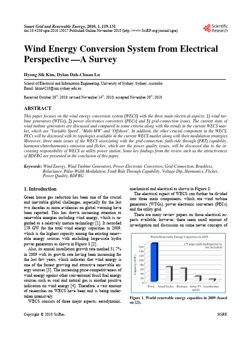
Smart Grid and Renewable Energy, 2010, 1, 119-131doi:10.4236/sgre.2010.13017 Published Online November 2010 (/journal/sgre)119 Wind Energy Conversion System from Electrical Perspective—A SurveyHyong Sik Kim, Dylan Dah-Chuan LuSchool of Electrical and Information Engineering, University of Sydney,Sydney, AustraliaEmail: hkim4210@.auReceived October 20th, 2010; revised November 14th, 2010; accepted November 20th, 2010ABSTRACTThis paper focuses on the wind energy conversion system (WECS) with the three main electrical aspects:1) wind tur-bine generators (WTGs),2) power electronics converters (PECs) and 3) grid-connection issues. The current state of wind turbine generators are discussed and compared in some criteria along with the trends in the current WECS mar-ket, which are ‘Variable Speed’,‘Multi-MW’ and ‘Offshore’. In addition, the other crucial component in the WECS, PECs will be discussed with its topologies available in the current WECS market along with their modulation strategies. Moreover, three main issues of the WECS associating with the grid-connection, fault-ride through (FRT) capability, harmonics/interharmonics emission and flicker, which are the power quality issues, will be discussed due to the in-creasing responsibility of WECS as utility power station. Some key findings from the review such as the attractiveness of BDFRG are presented in the conclusion of this paper.Keywords: Wind Energy, Wind Turbine Generators, Power Electronic Converters, Grid-Connection, Brushless, Reluctance, Pulse-Width Modulation, Fault Ride Through Capability, Voltage Dip, Harmonics, Flicker,Power Quality, BDFRG1. IntroductionGreen house gas reduction has been one of the crucial and inevitable global challenges, especially for the last two decades as more evidences on global warming have been reported. This has drawn increasing attention to renewable energies including wind energy, which is re-garded as a relatively mature technology [1]. It recorded 159 GW for the total wind energy capacities in 2009, which is the highest capacity among the existing renew-able energy sources with excluding large-scale hydro power generators as shown in Figure 1 [2].Also, its annual installation growth rate marked 31.7% in 2009 with its growth rate having been increasing for the last few years, which indicates that wind energy is one of the fastest growing and attractive renewable en-ergy sources [3]. The increasing price-competitiveness of wind energy against other conventional fossil fuel energy sources such as coal and natural gas is another positive indication on wind energy [4]. Therefore, a vast amount of researches on WECS have been and is being under-taken intensively.WECS consists of three major aspects; aerodynamic, mechanical and electrical as shown in Figure 2.The electrical aspect of WECS can further be divided into three main components, which are wind turbine generators (WTGs), power electronic converters (PECs) and the utility grid.There are many review papers on those electrical as-pects available; however, there seem small amount of investigation and discussion on some newer concepts ofFigure 1. World renewable energy capacities in 2009 (based on [2]).Wind Energy Conversion System from Electrical Perspective—A Survey 120Figure 2. Wind energy conversion system (based on [5,6]).WGTs as well as PECs along with its modulation strate-gies. The purpose of this paper is, therefore, to reviewthese three important electrical aspects of WECS withsome of the newer concepts for WTGs, PECs with theirmodulation strategies, and some of the grid connectionissues that have risen as the penetration of wind energyon the utility grid has been increasing rapidly in the lastfew years [4].The structure of this paper is as follows: wind turbinegenerators are firstly discussed in Section 2, followed byPECs and their modulation strategies in Section 3. Then,grid-connection issues of WECS will be addressed inSection 4. In Section 5, the discussion on these three com-ponents is presented and followed by the conclusion inSection 6.2. Wind Turbine Generators2.1. Wind Turbine Generators in the CurrentMarketWTGs can be classified into three types according to itsoperation speed and the size of the associated convertersas below:∙FSWT (Fixed Speed Wind Turbine)∙VSWT (Variable Speed Wind Turbine) with:o PSFC (partial scale frequency converter)o FSFC (full scale frequency converter)FSWT including SCIG (Squirrel-Cage Induction Gen-erator), led the market until 2003 when DFIG (DoublyFed Induction Generator), which is the main concept ofVSWT with PSFC, overtook and has been the leadingWTG concept with 85% of the market share reported in2008 [4]. For VSWT with FSFC, WRSG (Wound RotorSynchronous Generator) has been the main concept;however PMSG (Permanent Magnet Synchronous Gen-erator) has been drawing more attention and increasingits market share in the past recent years due to the bene-fits of PMSG and drawbacks of WRSG [7].Since there is much literature available on these WTGconcepts in the market such as [6-13], the following sec-tion will only address the two newer concepts of WTGs,which are BDFIG (Brushless Doubly Fed InductionGenerator) and BDFRG (Brushless Doubly Fed Reluc-tance Generator), followed by the discussion with thecomparison of them to the existing concepts.2.2. Two Newer WTG Concepts2.2.1. BDFIGBDFIG is one of the most popular VSWT with PSFCtypes in the current research area due to its inheritedcharacteristics of DFIG, which is the most popular WTGtype at the current market, along with its brushless aspectthat DFIG do not possess. As shown in Figure 3, BDFIGconsists of two cascaded induction machines; one is forthe generation and the other is for the control in order toeliminate the use of sliprings and brushes, which are themain drawback of DFIG.This brushless aspect increases its reliability, which isespecially desirable in offshore application [14,15]. Otheradvantages are reported in [6,16,17] including its capa-bility with low operation speed. On the other hand,BDFIG has relatively complex aspects in its design, as-sembly and control, which are some of the main disad-vantages of BDFIG [8].2.2.2. BDFRGThere is also another brushless and two-cascaded-statorconcept of VSWT with PSFC type in the research area,which is BDFRG. As shown in Figure 4, one distinctdesign compared with BDFIG is its reluctance rotor,which is usually an iron rotor without copper windings,which has lower cost than wound rotor or PM (perma-nent magnet) rotor.This design offers some advantages on top of the ad-vantages of BDFIG including higher efficiency, easierconstruction and control including power factor controlcapability as well as the cost reduction and higher reli-ability including its “fail-safe” operating mode due to itsreluctance rotor [18-21]. Due to its very high reliability,reluctance generators have also been of interest in air-craft industry where design challenges such as harsh en-vironment operation and stringent reliability exist [22,23]. On the other hand, some of the drawbacks for BDFRGexist such as complexity of rotor deign, its larger ma-chine size due to a lower torque-volume ratio and soforth [20,24,25].Wind Energy Conversion System from Electrical Perspective—A Survey121 Figure 3. The conceptual diagram of BDFIG.Figure 4. The conceptual diagram of BDFRG.2.3. Comparison of WTG ConceptsThe advantages and disadvantages of the six concepts,the four existing in the current market and the two newerconcepts discussed in the previous section are summa-rised in Table 1 [6-21,24,25].Based on the information in Table 1, Table 2 repre-sents a comparison of those six concepts with respect tothe five criteria; energy yield, cost, reliability, grid sup-port ability and technical maturity. For energy yield,PMSG has the highest rating followed by the otherVSWT concepts and SCIG has the lowest energy yieldwith 10-15% lower value than PMSG [26] due to its fixspeed aspect. However, SCIG has the lowest cost fol-lowed by BDFRG, and WRSG has the highest cost dueto its large size wound machine. It is interesting when‘energy yield per cost’ is considered based on the esti-mated levels on energy yield and cost in Table 2. Thehighest value is achieved by neither PMSG nor SCIG;BDFRG achieves the highest estimated levels on ‘energyyield per cost’, which is supported in [19]. Reliability isclosely related to the existence of brushes and sliprings,which is the main drawback of DFIG. The reason BDFIGis rated as ‘Medium-High’ despite of its brushless aspectis because it is new and has design complexity, whichbrings down reliability as the case of the newer GermanWTGs compared with older Danish WTGs reported in[12]. On the other hand, BDFRG is rated as ‘High’ de-spite of that it is as new concept as BDFIG. It is becauseof the ‘fail-safe’ characteristic of BDFRG, which enablesits robust operation in spite of the failure on its inverteror secondary stator. Grid support ability is affected main-ly by the size of the converter and the stator connection.VSWT with FSFC has high support ability due to its fullscale frequency converter. In the case of DFIG, withPSFC, it can only provide limited support to the grid dueto its directly connected stator that absorbs the effect ofgrid fault without any mitigation. It is reported thatBDFIG and BDFRG have improved characteristics undergrid fault [16] and for grid support ability [19] respec-tively. Lastly, the maturity of the technology is straight-forward as shown in Table 2 because SCIG, DFIG andWRSG have been developed for more than a couple ofdecades followed by PMSG. As mentioned before, BDFIGand BDFRG are newer concept and therefore more re-searches are needed in order to increase its technical ma-turity and hence to be applicable in the industry.2.4. Discussion on WTGsAs observed previously, there has been ‘variable speed’trend in the WT market due to its greater energy yieldalong with other advantages and will be so in the futurewith DFIG and PMSG leading the market base on thevarious data and literature [4,8,9,27]. The two newerconcepts, BDFIG and BDFRG are also in line with thistrend.Another distinct trend is offshore wind energy. It isreported that offshore wind resource has higher quality interms of its availability and constancy, and higher spatialavailability than onshore wind resource, which makesoffshore wind very attractive [28]. However, there existgreat technical challenges on its construction and main-tenance, because of its geological accessibility that greatlydepends on the weather condition, which is an unpre-dictable external factor. Due to this reason, offshore windhas only 1.2% of the world’s total installed wind energyshare (onshore and offshore) at the current market [3]and is reported to cost 1.5-2 times more than equal-sizeonshore wind application [29]. As discussed previously,DFIG is less attractive for offshore application due to itspre-planned maintenance for brush and sliprings whereasPMSG, BDFIG and BDFRG are more attractive due toits brushless aspect. BDFRG is especially attractive forits reliability due to its reluctance rotor as discussed pre-viously. Although offshore wind has low level of instal-lation at the present, the growth rate was reported to be30% in 2009 and is expected to continue to grow [3,28].Lastly, ‘Multi-MW’ trend is also observed at the cur-rent wind turbine market [4,9,27] due to the fact that lar-ger power station has lower cost per kWh. The size of theturbine in the current market has gone up to 5-6 MW oreven greater [27], supported by the increased technicallevel in design and construction. In terms of the cost ofthe material, DFIG and BDFRG are preferable overPMSG and BDFIG for this trend since PM material inPMSG is costly, and BDFIG has a wound rotor with theWind Energy Conversion System from Electrical Perspective—A Survey122Table 1. The advantages and disadvantages of the six WTG concepts.Generator Concept (Type) Advantages DisadvantagesSCIG (FSWT) ∙Easier to design, construct and control∙Robust operation∙Low cost∙Low energy yield∙No active/reactive power controllability∙High mechanical stress∙High losses on gearPMSG (VSWT-FSPC) ∙Highest energy yield∙Higher active/reactive power controllability∙Absence of brush/slipring∙Low mechanical stress∙No copper loss on rotor∙High cost of PM material∙Demagnetisation of PM∙Complex construction process∙Higher cost on PEC∙Higher losses on PEC∙Large sizeWRSG (VSWT-FSPC) ∙High energy yield∙Higher active/reactive power controllability∙Absence of brush/slipring∙Low mechanical stress∙Higher cost of copper winding∙Higher cost on PEC∙Higher losses on PEC∙Large sizeDFIG (VSWT-PSPC) ∙High energy yield∙High active/reactive power controllability∙Lower cost on PEC∙Lower losses by PEC∙Less mechanical stress∙Compact size∙Existence of brush/slipring∙High losses on gearBDFIG (VSWT-PSPC) ∙Higher energy yield∙High active/reactive power controllability∙Lower cost on PEC∙Lower losses by PEC∙Absence of brush/slipring∙Less mechanical stress∙Compact size∙Early technical stage∙Complex controllability, design and assembly∙High losses on gearBDFRG (VSWT-PSPC) ∙Higher energy yield∙High active/reactive power controllability∙Lower cost on PEC∙Lower losses by PEC∙Absence of brush/slipring∙No copper loss on rotor∙Less mechanical stress∙Easier construction∙Early technical stage∙Complex controllability and rotor design∙High losses on gear∙Larger size than DFIGTable 2. The comparison of the six different WTG concepts.Generator Concept Energy Yield Cost Reliability Grid Support Ability Technical Maturity SCIG Low Low High Low High PMSG High Medium-High High High Medium-High WRSG Medium-High High High High High DFIG Medium-High Medium Medium Medium High BDFIG Medium-High Medium Medium-High Medium-High Low BDFRG Medium-High Low-Medium High Medium-High LowWind Energy Conversion System from Electrical Perspective—A Survey 123two wound cascaded stator, which has greater amount of windings than DFIG or BDFRG.3. Power Electronic Converters3.1. Topology of Power Electronic ConvertersAs the amount of the installed VSWT increased, so has the importance of PECs in WECS since it is the interface between WTGs and the electrical grid [1,11,30]. There are three types of converters widely available in the cur-rent wind energy market: Back-to-back PWM converter, multilevel converter and matrix converter.3.1.1. Back-to-back PWM ConvertersBack-to-back PWM converter, which is also referred as ‘two-level PWM converter’, is the most conventional type among the PEC types for VSWT. As shown in Fig-ure 5, it consists of two PWM-VSIs (voltage source in-verters) and a capacitor in between. This capacitor is often referred as a ‘DC link capacitor’ or ‘decoupling capacitor’ since it provides a separate control in the in-verters on the two sides, which are ‘machine’ and ‘grid’ side. In addition, it has lower cost due to its maturity [12].However, the DC link capacitor also becomes the main drawback of the PWM converter because it decreases the overall lifetime of the system [31]. There are other dis-advantages including switching losses and emission of high frequency harmonics, which results in additional cost in EMI-filters [1,12].3.1.2. Multilevel ConvertersCompared with two-level PWM converter, multilevel (ML) converter has three or more voltage levels, which results in lower total harmonic distortion (THD) than back-to-back PWM converter does [32]. In addition, ML converter offers higher voltage and power capability, which advocates the trend of ‘Multi-MW’ wind turbine [1,33]. Another advantage is that switching losses are smaller in ML converter than two-level PWM converter by 25% [34].One of the disadvantages on ML converter is the volt-age imbalance caused by the DC link capacitors [35,36]. Another disadvantage in some ML converter designs is uneven current stress on the switches due to its circuit design characteristic. The cost associated with the highFigure 5. Basic schematics of Back-to-Back PWM converter (based on [12]). more number of switches and the complexity of control are two other drawbacks.Since the first proposed design of ML converter, the neutral-point clamped three-level converter in 1981 [36,37], there have been various designs for ML converters in-cluding the followings [33,35,36,38]:∙Neutral Point Clamped (NPC) ML converter∙Cascade Half-Bridge (CHB) ML converter∙Fly-capacitor (FLC) ML converterThe detail of each design, which is beyond the scope of this paper, can be found in the literatures [33,35,36, 38].Out of these three ML converter designs, NPC ML converter is commonly utilised in WECS, especially in multi-MW scale WECS, due to its maturity and advan-tages [36,39]. Main drawback exists, however, with 3L- NPC (3 level-NPC) design, which is the uneven loss dis-tribution among the semiconductor devices, limiting output power of the converter [40,41]. This drawback has been overcome with the replacement of the clamping diode with the active switching devices. This modified design of NPC is referred as ‘Active NPC’ (ANPC), which was first introduced in 2001 [41,42], as shown in Figure 6. There are many advantages of ANPC including higher power rating than normal NPC by 14% [40] and robustness against the fault condition [43].3.1.3. Matrix ConvertersMatrix converters have a distinct difference from the previous two converters in a way that it is an AC-AC converter without any DC conversion in between, which indicates the absence of passive components such as the DC link capacitor and inductor in the converter design. As shown in Figure 7, the typical design of matrix con-verters consists of 9 semi-conductors that are controlled(a) (b)Figure 6. One inverter cell of (a) NPC and (b) ANPC (based on [12,36]).Wind Energy Conversion System from Electrical Perspective—A Survey124Figure 7. Basic schematics of matrix converter (based on [12,45]).with two control rules to protect the converter; three switches in a common output leg must not be turned on at the same time and the connection of all the three out-put phases must be made to an input phase constantly [12]. There are some advantages of matrix converters. The absence of DC link capacitor results in increased efficiency and overall life time of the converter as well as the reduced size and cost compared with PWM-VSI converter [4,44]. The thermal characteristic of the matrix converter is also another advantage since it can operate at the temperature up to 300˚C, which enables to adopt new technologies such as high temperature silicon carbide devices [44]. On the other hand, some of the reported disadvantages include; the limitation on the output volt-age (86% of the input voltage), its sensitivity to the grid disturbances and rapid change of the input voltage, higher conducting losses and higher cost of the switch components than PWM-VSI converter [12,32]. Further technical details of matrix converter can be found in [44]. 3.1.4. Discussion on PECIn this section, the PECs will be discussed with the crite-ria such as their power loss, loss distribution, efficiency, harmonic performance and cost.In terms of power losses, it is widely reported that ML VSCs have less power losses than 2L VSIs with 3-Level Neutral Point Clamped VSIs (3L-NPC) having even lower amount of losses over 3-Level Flying Capacitor VSIs (3L-FLC) [46-48]. This advantage of 3L-NPC, however, inherits poor power loss distribution, which is the main drawback of 3L-NPC as mentioned previously. Loss distribution is an important aspect in PEC since uneven loss distribution means uneven stress distribution among the semiconductor devices and this results the most stressed switching device to limit the total output power and switching frequency [49]. In [46,47], uneven loss distribution of 3L-NPC is reported along with other topologies such as 2L-VSI and 3L-FLC, which have even distribution. As mentioned previously, ANPC is the to-pology to reduce the unevenness among the switching devices and it is reported that 3L-ANPC possess an ad-vantage of 3L-FLC on its natural doubling of switching frequency, without flying-capacitors [50].Harmonic performance is another crucial criterion of PEC, especially for WECS as the impact of WECS on power quality of the power grid is increasing due to its increasing penetration level. The comparison on har-monic performance is commonly measured by total har-monic distortion (THD) or weighted THD (WTHD). A comparison on THD of 2L-VSI, 3L-NPC and matrix converter with PMSG is undertaken in [51] and 3L-NPC provides the lowest value of THD among the three to-pologies. This result verifies that THD decreases with increasing number of levels [46].Different PEC topologies consist of components with variable numbers and sizes that result variation in cost. Although 2L-VSI has less number of components com-pare to ML VSIs, it is estimated to be more costly due to its large LC filter, which is the result of compromise for high efficiency and low THD that ML can achieve with smaller LC filter [47,48]. Matrix converters would lie in between 2L VSIs and 3L VSIs since it has smaller num-ber of semiconductors and LC filters are required to minimise the switching frequency harmonics [52]. The cost estimation would be similar for both 3L-NPC and 3L-FLC since the excessive cost for the larger LC filter and semiconductors would be compensated with the cost for flying capacitors by considering the cost estimation in [47] with the constant switching frequency. In [53], comparison between 3L-ANPC and 3L-NPC is conducted with different IGBT ratings available in the market. In the literature, it is found that 3L-NPC is most economical (i.e. lest cost per MVA) with 2.3 kV IGBT modules at any switching frequency between 300 Hz to 1050 Hz. However, 3L-ANPC becomes more cost-effective with 3.3 kV and 4.16 kV at switching frequency over 750 Hz. In summary, it is evident that 3L-ANPC is a very at-tractive PEC topology for WECS, which is increasing its power rating, operates with high switching frequency (typically 2~5 kHz [47,51,54-57]) and requires low har-monic emission.3.2. Modulation MethodsAlong with the converter topologies, there are some modulation strategies available to produce a desired level of output voltage and current in lower frequency. Pulse- width modulation (PWM) is one of the most widely used modulation strategies for PEC with AC output, hence, this section will focus on PWM schemes for ML con-verters.While the primary goal of PWM is to produce a tar-geted low-frequency output voltage or current, it is also essential for PWM schemes to minimise the impact on the quality of the output signals such as harmonic distor-tion.Wind Energy Conversion System from Electrical Perspective—A Survey 125Among the vast amount of proposed PWM schemes, majority of them can be categorised into the following three types despite of different converter topologies [33, 36,53]:∙Carrier-Based PWM∙Space Vector Modulation (SVM)∙Selective Harmonic Elimination (SHE)These three PWM strategies will be explained in detail on the next section.3.2.1. Carrier-Based PWMCarrier-based PWM strategy has been widely utilised as the basic logic of generating the switching states is sim-ple. The basic principle is to compare a low frequency sinusoidal reference voltages to high frequency carrier signals, then produce the switching states every time the reference signal intersects carrier signals. The number of carrier signals is defined as (N-1), where N is the number of the level of multi-level VSI (eg. N = 3 for 3-Level NPC VSI) [58].The basic control diagram and modulation signals of 3-Level VSI are represented in Figure 8.From the conventional schemes, there are some modi-fied techniques proposed with multi-level or multi-phase methods in order to reduce distortion in ML inverters [59]. Basic concepts of those are shown in Figure 9.3.2.2. Space Vector Modulation (SVM)Space vector modulation (SVM) is the PWM method based on the space vector concept with d-q transforma-tion that is widely utilised in AC machines. With the de-velopment of microprocessors, it has become one of the most widely used PWM strategies for three-phase con-verters due to some of its advantages including high voltage availability, low harmonics, simple digital im-plementation and wide linear modulation range, which is one of the main aims of PWM [4,47,60].There are N3 switching states in N-level PWM inverter so in the case of 3-Level NPC VSI, there are 27 (= 33) possible switching states. As shown in Figure 10, these switching states define reference vectors, which are rep-resented by the 19 nodes in the diagram with the four classification of ‘zero’ (V0), ‘small’ (V Si), ‘medium’ (V Mi) and ‘large’ (V Li), where i = 1,2,…,6 [61]. The difference between the numbers of the switching states and space vectors indicate that there is redundancy of switching states existing for some space vectors. As indicated in Figure 10, one ‘zero’ space vector (i.e.V0) can be generated by three different switching states and six ‘small’ space vector (i.e.V Si) by two different switching states each. These redundancies provide some benefits including balancing the capacitor voltages in 3L-NPC VSI [36]. The basic principle of SVM is to select three nearest(a)(b)Figure 8. (a) Control diagram, (b) Modulation signal (sources from [36]).vectors that consist of a triangle in the space vector dia-gram that the tip of a desired reference vector is located, and generate PWM according to the switching states of those selected vectors. There are many researches on SVM to improve on various aspects such as the im-provement in neutral point (NP) balancing at higher modulation indexes [62] and the reduction of the size of DC-link in control loop for renewable application such as WECS [63].3.2.3. Selective Harmonic EliminationThe basic principle is to calculate N number of switching angles that are less than π/2 for a N-Level inverter through N number of the nonlinear equation with Fourier expansion of output voltage [64]. One equation is used toWind Energy Conversion System from Electrical Perspective—A Survey126(a)(b)Figure 9. (a) Multi-level PWM, (b) Multi-phase PWM (sources from [33]).Figure 10. Normalised space vector diagram for the three- level NPC converter (based on [61]).control the fundamental frequency through the modula-tion index and the other N-1 equations are used for elimination of the low-order harmonics components [59]. In the case of 3-Level VSI, 5th and 7th harmonic compo-nents are the two lowest-order harmonics to be elimi-nated since 3rd harmonic component is cancelled by the nature of three-phase [53]. Figure 11 depicts an example of the 3-Level SHE with 3 switching angles, a 1, a 2 & a 3 [36].It is well-known that SHE strategy provides good harmonic performance in spite of the low switching fre-quency due to its harmonic elimination nature [53,65]. Another advantage is the reduction on its switching loss due to the low switching frequency [36]. However, there are some disadvantages exist including its heavy compu-tational cost and narrow modulation range [59,65]. There are many researches on SHE such as NP balancing for 3L-NPC [36] and the increase of the number of elimi-nating low-order harmonics with simple in formulation [66].3.2.4. Discussion on Modulation MethodAmong the three modulation methods discussed above, CB-PWM [67-70] and SVM [32,56,71-74] are widely utilised in WECS. However, SHE strategy has not been utilised in WECS to the best knowledge of the author despite of its active researches with resent PEC tech-nologies such as 5-Level ANPC VSI [75]. The authors in [53] suggest the combination of using 2L SVM and SHE schemes for the switching frequency f sw ≤ 500 Hz whereas the combination of 2L SVM and 3L SVM for f sw > 500 Hz due to their performances with respect to the modulation index and switching frequency. This could be one reason for SHE schemes not to be utilised in WECS where high switching frequency is used.However, if the reason of high switching frequency in WECS is for the quality of output power, lower switch-ing frequency can be adapted with SHE strategy in WECS for high quality of output power. This would in-crease the efficiency of WECS due to less switching losses and also this will reduce a cost of filter circuits since the size of the filter would be smaller with the na-ture of harmonic elimination of SHE.Figure 11. 3-level SHE (Source from [36]).。
- 1、下载文档前请自行甄别文档内容的完整性,平台不提供额外的编辑、内容补充、找答案等附加服务。
- 2、"仅部分预览"的文档,不可在线预览部分如存在完整性等问题,可反馈申请退款(可完整预览的文档不适用该条件!)。
- 3、如文档侵犯您的权益,请联系客服反馈,我们会尽快为您处理(人工客服工作时间:9:00-18:30)。
中英文对照外文翻译(文档含英文原文和中文翻译)附件1:翻译译文风力发电对电力系统的影响摘要风力发电依赖于气象条件,并逐渐以大型风电场的形式并入电网,给电网带来各种影响。
电网并未专门设计用来接入风电,因此如果要保持现有的电力供应标准,不可避免地需要进行一些相应的调整。
讨论了在风电场并网时遇到的各种问题。
由于风力发电具有大容量、动态和随机的特性,它给电力系统的有功/无功潮流、电压、系统稳定性、电能质量、短路容量、频率和保护等方面带来影响。
针对这些问题提出了相应的解决建议和措施,以及更好利用风力发电。
关键词:风力发电;电力系统;影响;风电场1.引言人们普遍接受,可再生能源发电是未来电力的供应。
由于电力需求快速增长,对以化石燃料为基础的发电是不可持续的。
正相反,风力发电作为一种有前途的可再生能源受到了很多关注。
当由于工业的发展和在世界大部分地区的经济增长而发电的消费需求一直稳步增长时,它有减少排放和降低不可替代的燃料储备消耗的潜力。
当大型风电场(几百兆瓦)是一个主流时,风力发电越来越更受欢迎。
2006年间,世界风能装机容量从2005年的59091兆瓦达到74223兆瓦。
在2006年极大的生长表明,决策者开始重视的风能发展能够带来的好处。
由于到2020年12%的供电来于1250GW的安装风电装机,将节约累积10771000000吨二氧化碳[1]。
大型风电场的电力系统具有很高的容量,动态随机性能,这将会挑战系统的安全性和可靠性。
而提供电力系统清洁能源的同时,风农场也会带来一些对电力系统不利的因素。
风力发电的扩展和风电在电力系统的比重增加,影响将很可能成为风力集成的技术性壁垒。
因此,应该探讨其影响和提出克服这些问题的对策。
2.风力发电发展现状从全球风能委员会(GWEC)的报告中,拥有最高装机容量总数的国家是德国(20621兆瓦),西班牙(11615兆瓦),美国(11603兆瓦),印度(6270兆瓦)和丹麦(3136兆瓦)。
世界范围内十三个国家现在可以算是达到1000兆瓦的风力发电能力,法国和加拿大在2006达到这一阈值。
如图1所示,直到2006年12月世界累计装机容量前10名[2]。
图1 到2006年12月世界累计装机容量中国开始发展风电很晚。
只有在90年代它才走向市场化的发展和规模建设。
这些年新增累积装机容量如图2显示。
单一机组容量从100千瓦,200千瓦,300千瓦600千瓦,750千瓦,1500千瓦逐步增加。
图2 在中国累计和新增加安装的风力发电能力在2006年中国通过安装风能的1347兆瓦,增加了一倍以上的总量容量,比去年的数值增长了70%。
这给中国带来多达2604兆瓦的能力,使中国成为世界第六个最大的市场。
中国市场在2006年大幅增长,这预计将继续增长并加快增长。
根据经批准的和在建设中的项目,在2007年将安装超过1500兆瓦。
到2010年底在中国的风电目标为5000兆瓦[3]。
3.风力发电项目的特点从风能的角度来看,风能资源的最显特点是其变化性。
风电场输出的随机变化主要根源于风速的波动和方向。
无论是地理性和时间性,风是很易变的。
此外,无论是在空间和时间上,这种变化性持续的范围非常广泛。
图3.布鲁克海文国家实验室工作的基础上的农场风谱图由于时间和高度的功能,风速不断变化。
风变化的时间尺度显示在图3的风力频谱图上[4]。
在一秒到分钟的范围阵风引起动荡的高峰。
每日的峰值取决于每天的风速变化和天气高峰取决于天气变化,通常因每天或每周而异,但也包括季节性周期。
从电力系统的角度来看,湍流高峰可能会影响风力发电的电能质量。
然而,昼夜和天气的高峰,可能会影响长期的电力系统的平衡,在这样的系统中风速预测起着显著作用。
另一个重要问题是风能资源的长期变化。
应知道加速到中心高度的风来计算风电场的输出。
大量风速测量表明,风速在一年中大多数是柔和的,介于0和25米/秒的概率是相当大的;年均风速受制于威布尔分布[5],如公式(1)。
错误!未找到引用源。
(1) 其中:V是平均风速;k为形状参数;c是尺度参数。
风力发电机的输出之间的关系PW和风速集线器V的高度可以近似表示为风力发电机的输出与风速或分段函数的曲线,如公式(2)。
错误!未找到引用源。
(2)其中:PW是额定功率的风力发电机组的输出;V是风速达枢纽的高度VCI是停机风速;VCO被切出风速;VR被评为风速。
4.风力发电对电力系统的影响在电力系统中风力发电面临大型风电场对电网一体化的基本技术限制。
风力发电对电力系统的影响包括有效功和无效功,电压,系统稳定性,电能质量,短路容量和基础设施的特点由于高容量的风力发电的动态和随机性能。
在技术上,它通过以下方式影响和必须详细研究:(1)有功和无功流风力发电是一个间歇性和随机的电源,将功率流复杂化。
由于为了捕获更多的风能能源,许多风电场建成远离负荷中心,总有传输风力发电一些的障碍。
当引进额外的风力发电时一些传输或配电线路和其他电气设备可能过载。
因此,应确保互相连接传输或配电线路不过载。
有功和无功要求,都应予以调查。
无功功率应不仅在PCC中产生,但也通过整个网络产生,并应本地补偿[6]。
用于常规发电机的分析的方法是确定的,而忽略了不确定性的风速和负荷预测。
因此,概率性的方法是比较适合风力发电的。
约束以概率形式描述,并且预期参数值,如电压和功率,可以被计算。
(2)电压调节一旦风电场已经确定了其地点,连接到电网的点必须确定。
对于小型风力发电场,可以在低电压下连接,从而节省了开关设备、电缆和变压器的成本。
如果拟议的发展规模太大导致不可以与当地分布电压的连接,进而不能满足较高的电压传输网络的需要[7]。
在电力系统中随着风力发电安装容量的增加,风力发电的变化引起电压变化,特别是如果并入电网,这可能不是专门设计用于迎合重要和可能快速变化的负载,这是由风力发电变化引起的。
因此,需要采取监管措施,使电压保持在指定的范围内。
然而,为了控制电压,这可能导致增加对无功功率的辅助服务[8]。
(3)系统的稳定性在风力发电的电力系统中,电压稳定和频率的稳定性都受到风功率集成影响,这不仅是因为风力发电的加入将改变流量分布,也因为风力发电机与传统的同步机无论是在稳态或瞬态状态时相比表现不同[9]。
对于目前的风力发电场,当发生干扰时,保护操作通常是切断风电场之间的连接电网。
因此,在这种时刻的暂态稳定是非常重要的,尤其是当大型风电场的有机结合时最为重要。
然而,由于电网结构,风也可能使电源集成系统的瞬态稳定性差。
因此,不同的电力系统,暂态稳定性应分别进行分析。
固定速度的风力涡轮机输出有功功率时,它吸收无功功率。
“风电场无功功率的整体需求是相当大,从而导致减少在PCC附近地区的电压稳定。
与此相反,双馈变速风力发电机组对无功功率有一定的控制能力。
根据不同的操作和控制计划,这种风力发电机组可以吸收或输出无功功率控制电压,有利于电压稳定。
电压稳定也与短路容量相关,传输的PCC行比R / X和在风力发电场使用的无功补偿方法有关。
(4)电能质量风力发电的波动和相关电源(AC或DC)的传输、供电质量有直接的影响。
结果,大量的电压波动,可能会导致电压在调控范围外变化,以及违反闪烁和其他电源的质量标准。
在连续的运行和开关操作,风力发电机组,引起电压波动和闪烁,这些因素是风力发电影响电网电能质量的主要因素。
对于变速风力涡轮机和恒定频率,转换器造成的谐波问题,也应考虑。
风力涡轮机对电网干扰有不同的原因,其中大多原因是风力机本体。
有关参数列于表1[10]。
平均发电量,湍流强度及风切变与气象和地理条件因素相关。
所有其他的原因不仅归咎于电器元件的特点,如发电机,变压器等,也是转子和传动系统的空气动力学和机械性能的原因。
涡轮形式(即变量与主要固定的速度档位与节距调节)对风力涡轮机和风力发电场的电能质量特性有重要性。
闪烁是由风力发电机组的有功功率或无功功率的的波动造成的。
固定速度的风力发电机闪烁的主要原因是塔的尾流。
而变速风力发电机,平滑了快速功率波动,塔的尾流不影响输出功率。
因此,变速风力发电机组的闪烁一般比定速闪烁风力发电机低。
表1.风力发电机和风力发电厂对电网造成的影响参数原因电压升高电能生产开关操作塔影效应电压波动和闪烁叶片调节误差偏航误差风切变风速波动谐波变频器晶闸管控制器电压峰值和谷值开关操作(5)短路容量往往是大多数的风力发电场远离负荷中心建造,这意味着他们之间和其他间的电力系统的电气之间的距离,是相当远的。
有一常理说,长电距离,使电压变化较大,但短路问题少[11]。
然而,风力发电场将能够给未来的电力系统运行的短路电流计算带来越来越重要的影响。
原因是双重的。
一个是上述的事实,风力发电网站通常是远离的传统的电力中心。
这意味着短路电流的分布可能产生了很大的变化,导致一个完全不同的短路容量地图。
其他事实的原因是,今天,越来越多的风力发电,特别是以所谓的大型风力发电场(数百兆瓦)的形式。
在风电场大量的个别单位连接在一起,总代能力将大大上升。
风电场对相邻节点短路能力有很大影响,然而对远离PCC节点的影响不大[9]。
因此,当具有大容量的风场并入电网时,相邻变压器和交换机的容量可能需要增加。
应该进一步研究的是:如何判断风力发电对现有网络上的电气设备短路电流额定值的影响。
(6)频率调整为了在规定的标准范围内控制电力系统频率,要求一些发电厂向电网公司提供频率控制配套服务。
然而,风力发电量总额的增加,其变化频率输出是一个很重要的影响[8]。
(7)保护电流在风电场和电网之间的流动是双向的,这是在保护的设计和配置应予以考虑的。
无论风力发电机采用何种发电机,风电场的整合将增加电网故障水平,进而影响原有的电网保护装置继电器的设置。
这可能需要增加新的保护装置或修改原有保护设备的继电器的设置。
尤其是如果风电场连接到分配网络,断路器可能在风电场装机容量增加时产生超负荷[8]。
5.减轻风力发电的影响的对策无功补偿设备的应用,如静止无功补偿(SVC)和静止同步补偿器(STATCOM)在风力发电中减轻其对电力系统的影响起着重要作用。
为了保持电压等级,电网公司可以提供额外的或升级的电压控制设施。
无功补偿设备应该安装在风电场升压变电站,这具有快速响应特性,并且可不断调节,如在SVC和STATCOM等。
为了减少风力发电造成的电压波动和闪烁,既需要速度控制应加以改善,以便和俯仰角控制最大限度地减少了风力发电机的输出波动,而风力发电机的输出最大化。
同时,如在风场安装辅助设备SVC和储能装置也可以减轻电压波动和闪烁。
在大多数情况下,快速作用无功补偿设备,包括SVC和STATCOM,应被纳入为提高网络的暂态稳定的设备之中。
从风力发电方面,它可以通过不断的功率因数控制或恒压控制提高电力系统的电压稳定增加风力发电的渗透。