自动控制理论第二章习题
自动控制原理-第2章习题解答精选全文完整版
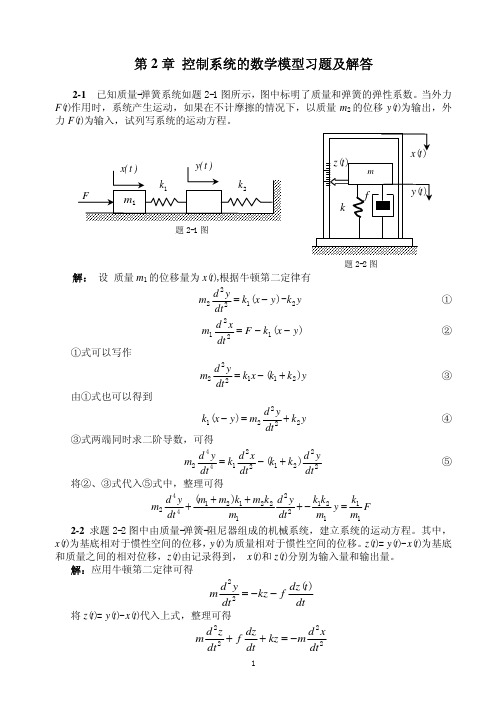
第2章 控制系统的数学模型习题及解答2-1 已知质量-弹簧系统如题2-1图所示,图中标明了质量和弹簧的弹性系数。
当外力F (t )作用时,系统产生运动,如果在不计摩擦的情况下,以质量m 2的位移y (t )为输出,外力F (t )为输入,试列写系统的运动方程。
解: 设 质量m 1的位移量为x (t ),根据牛顿第二定律有y k y x k dt yd m 21222-)(−= ①)(1221y x k F dtxd m −−= ②①式可以写作y k k x k dtyd m )(211222+−= ③由①式也可以得到y k dtyd m y x k 22221)(+=− ④③式两端同时求二阶导数,可得2221221442)(dty d k k dt x d k dt yd m +−= ⑤将②、③式代入⑤式中,整理可得F m k y m k k dty d m k m k m m dt y d m 1112122122121442)(=−++++ 2-2 求题2-2图中由质量-弹簧-阻尼器组成的机械系统,建立系统的运动方程。
其中,x (t )为基底相对于惯性空间的位移,y (t )为质量相对于惯性空间的位移。
z (t )= y (t )- x (t )为基底和质量之间的相对位移,z (t )由记录得到, x (t )和z (t )分别为输入量和输出量。
解:应用牛顿第二定律可得dtt dz f kz dt y d m )(22−−= 将z (t )= y (t )- x (t )代入上式,整理可得2222dtx d m kz dt dz f dt z d m −=++题2-2图题2-1图解:(a )引入中间变量u c (t)表示电容器两端的电压。
根据基尔霍夫电流定律有o c c u R u R dt du C2111=+ 根据基尔霍夫电压定律有o i c u u u −=联立消去中间变量,可得描述输入量u i (t )和输出量u o (t )之间关系的微分方程为i i o o u R dt du C u R R R R dt du C121211+=++ (b )引入回路电流i (t )和电容器两端的电压u c (t)作为中间变量,根据基尔霍夫电压定律有i o u u i R =+1 另有电容元件的元件约束关系方程dtdu Ci c =和i R u u o c 2−=联立求解,消去中间变量可得i i o o u R dt du C u R R R R dt du C121211+=++(c )设电容器C 2两端的电压为u c 2(t),根据基尔霍夫电流定律有dtduC u u R dt u u d C c o i o i 2211)(1)(=−+− ①求导可得22221221)(1)(dtu d C dt u u d R dt u u d C c o i o i =−+− ② 另有输出支路电压方程o c c u u dtdu C R =+2222 等式两边求导有dtdu dt du dt u d C R oc c =+222222 ③将①、②代入③式,整理可得i ii ooo u C R dt du C R C R C R dt u d C R u C R dt du C R C R C R C R dt u d C R 2121221121221212122112121122+++=++++2-4 试求题2-4图所示有源RC 电路的微分方程,其中u i (t )为输入量,u o (t )为输出量。
自动控制原理课后习题答案第二章
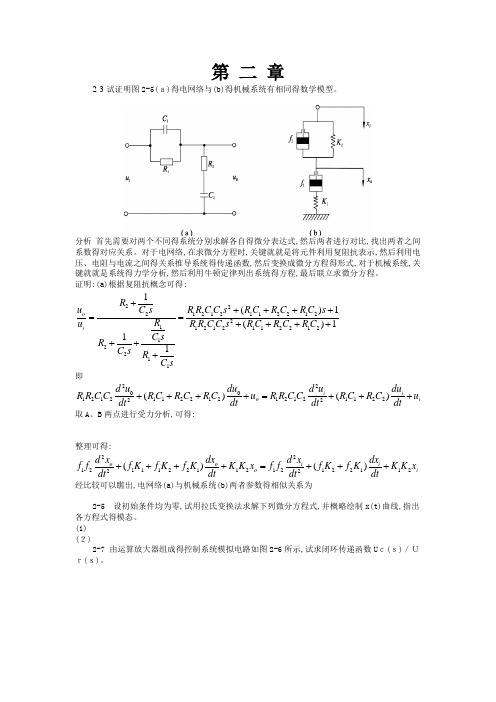
第二章2-3试证明图2-5(a)的电网络与(b)的机械系统有相同的数学模型。
分析首先需要对两个不同的系统分别求解各自的微分表达式,然后两者进行对比,找出两者之间系数的对应关系。
对于电网络,在求微分方程时,关键就是将元件利用复阻抗表示,然后利用电压、电阻和电流之间的关系推导系统的传递函数,然后变换成微分方程的形式,对于机械系统,关键就是系统的力学分析,然后利用牛顿定律列出系统的方程,最后联立求微分方程。
证明:(a)根据复阻抗概念可得:即取A、B两点进行受力分析,可得:整理可得:经比较可以看出,电网络(a)和机械系统(b)两者参数的相似关系为2-5 设初始条件均为零,试用拉氏变换法求解下列微分方程式,并概略绘制x(t)曲线,指出各方程式的模态。
(1)(2)2-7 由运算放大器组成的控制系统模拟电路如图2-6所示,试求闭环传递函数Uc(s)/Ur(s)。
图2-6 控制系统模拟电路解:由图可得联立上式消去中间变量U1和U2,可得:2-8 某位置随动系统原理方块图如图2-7所示。
已知电位器最大工作角度,功率放大级放大系数为K3,要求:(1) 分别求出电位器传递系数K0、第一级和第二级放大器的比例系数K1和K2;(2) 画出系统结构图;(3) 简化结构图,求系统传递函数。
图2-7 位置随动系统原理图分析:利用机械原理和放大器原理求解放大系数,然后求解电动机的传递函数,从而画出系统结构图,求出系统的传递函数。
解:(1)(2)假设电动机时间常数为Tm,忽略电枢电感的影响,可得直流电动机的传递函数为式中Km为电动机的传递系数,单位为。
又设测速发电机的斜率为,则其传递函数为由此可画出系统的结构图如下:--(3)简化后可得系统的传递函数为2-9 若某系统在阶跃输入r(t)=1(t)时,零初始条件下的输出响应,试求系统的传递函数和脉冲响应。
分析:利用拉普拉斯变换将输入和输出的时间域表示变成频域表示,进而求解出系统的传递函数,然后对传递函数进行反变换求出系统的脉冲响应函数。
自动控制原理课后习题答案第二章
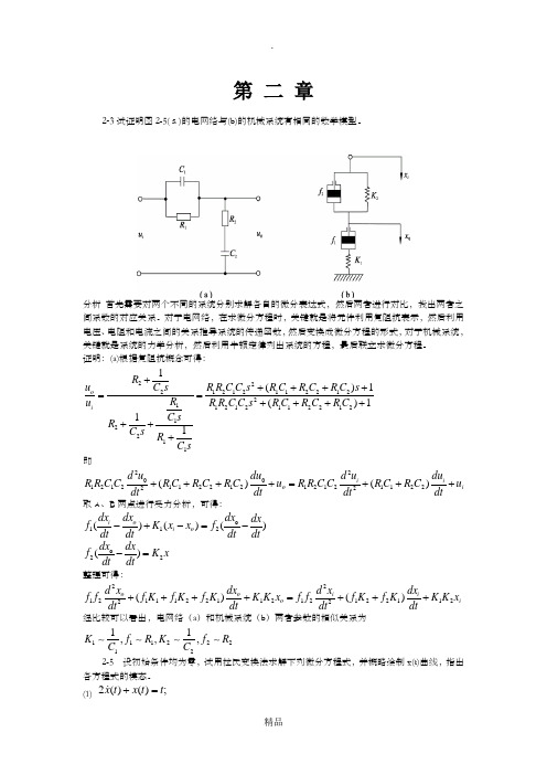
第 二 章2-3试证明图2-5(a)的电网络与(b)的机械系统有相同的数学模型。
分析 首先需要对两个不同的系统分别求解各自的微分表达式,然后两者进行对比,找出两者之间系数的对应关系。
对于电网络,在求微分方程时,关键就是将元件利用复阻抗表示,然后利用电压、电阻和电流之间的关系推导系统的传递函数,然后变换成微分方程的形式,对于机械系统,关键就是系统的力学分析,然后利用牛顿定律列出系统的方程,最后联立求微分方程。
证明:(a)根据复阻抗概念可得:2221212112212211212112212122111()1()111oiR u C s R R C C s R C R C R C s R u R R C C s R C R C R C C sR C s R C s+++++==+++++++即220012121122121212112222()()i i o id u du d u duR R C C R C R C R C u R R C C R C R C u dt dt dt dt++++=+++取A 、B 两点进行受力分析,可得:o 112()()()i o i o dx dx dx dx f K x x f dt dt dt dt -+-=- o 22()dx dxf K x dt dt -= 整理可得:2212111221121212211222()()o o i i o id x dx d x dx f f f K f K f K K K x f f f K f K K K x dt dt dt dt ++++=+++经比较可以看出,电网络(a )和机械系统(b )两者参数的相似关系为1112221211,,,K f R K f R C C2-5 设初始条件均为零,试用拉氏变换法求解下列微分方程式,并概略绘制x(t)曲线,指出各方程式的模态。
(1) ;)()(2t t x t x =+(2))。
自动控制理论 机械工业出版社 课后习题答案 夏德岑_第三版 PDF可打印
, t 0
比较上述两种情况, 可见有 z 1 零点时, 单位脉冲响应的振幅较无零点时小, 而且产生相移, 相移角为 arctg
1 2 n 。 1 n
2.单位阶跃响应 (a) 无零点时
ct 1
2 n t 1 2 t arctg 1 e sin n 1 2
G( s) 2a ss (2 a) s (2 2a)
2
根据条件(1) ,可得
Kv 1 2a 0.5 esr 2 2a
解得 a 1 ,于是由系统的开环传递函数为
G( s) 2 ss 3s 4
2
3-10
1M 2M
3t
s
p p
46.6%, t s 7.99s2%, ( n 2.12rad / s, 0.24) 16.3%, t s 8s2%, ( n 1rad / s, 0.5)
C m s 60 U a s s La Js 2 La f Ra J s Ra f C eC m 2
2-4
C s Rs
K A C m 60 iL a Js 3 iL a f Ra J s 2 i Ra f C eC m s K A C m 2
C 2 lim
s 0
d2 2(0.1s 2 s 10) 20(0.2s 1) 2 s lim 0 e s 0 ds 2 (0.1s 2 s 10) 3
(1)
s (t ) r (t ) R0 ,此时有 rs (t ) R0 , r r (t ) 0 ,于是稳态误差级数为 s esr t C0 rs (t ) 0 , t 0
自动控制原理课后习题答案第二章
解:由图可得
联立上式消去中间变量U1与U2,可得:
2-8某位置随动系统原理方块图如图2-7所示。已知电位器最大工作角度,功率放大级放大系数为K3,要求:
(1) 分别求出电位器传递系数K0、第一级与第二级放大器得比例系数K1与K2;
(2) 画出系统结构图;
(3) 简化结构图,求系统传递函数。
证明:(a)根据复阻抗概念可得:
即 取A、B两点进行受力分析,可得:
整理可得:
经比较可以瞧出,电网络(a)与机械系统(b)两者参数得相似关系为
2-5 设初始条件均为零,试用拉氏变换法求解下列微分方程式,并概略绘制x(t)曲线,指出各方程式得模态。
(1)
(2)
2-7由运算放大器组成得控制系统模拟电路如图2-6所示,试求闭环传递函数Uc(s)/Ur(s)。
2-10试简化图2-9中得系统结构图,并求传递函数C(s)/R(s )与C(s)/N(s)。
图2-9 题2-10系统结构图
分析:分别假定R(s)=0与N(s)=0,画出各自得结构图,然后对系统结构图进行等效ቤተ መጻሕፍቲ ባይዱ换,将其化成最简单得形式,从而求解系统得传递函数。
解:(a)令N(s)=0,简化结构图如图所示:
可求出:
令R(s)=0,简化结构图如图所示:
所以:
(b)令N(s)=0,简化结构图如下图所示:
所以:
令R(s)=0,简化结构图如下图所示:
2-12 试用梅逊增益公式求图2-8中各系统信号流图得传递函 数C(s)/R(s)。
图2-11 题2-12系统信号流图
解:
(a)存在三个回路:
存在两条前向通路:
所以:
(3)简化后可得系统得传递函数为
自动控制理论第二章习题答案
− u0 R
+ 2C1
d (ui − u0 ) dt
= C2
du0 dt
−
C1C2
R
d 2uC1 dt 2
即: ui R
− u0 R
+ 2C1
dui dt
− 2C1
du0 dt
= C2
du0 dt
−
C1C2
R
d 2ui dt 2
+
C1C2
R
d 2u0 dt 2
整理得:
C1C2
R
d 2u0 dt 2
+
胡寿松自动控制原理习题解答第二章
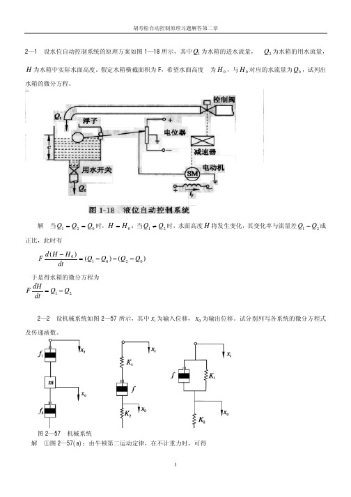
2—1 设水位自动控制系统的原理方案如图 1—18 所示,其中 Q1 为水箱的进水流量, Q2 为水箱的用水流量, H 为水箱中实际水面高度。假定水箱横截面积为 F,希望水面高度 为 H 0 ,与 H 0 对应的水流量为 Q0 ,试列出
水箱的微分方程。
解 当 Q1 = Q2 = Q0 时,H = H 0 ;当 Q1 ≠ Q2 时,水面高度 H 将发生变化,其变化率与流量差 Q1 − Q2 成
y
=
f
(
x0
)
+
df (x) dx
x0
(
x
−
x0
)
即 F − F0 = K1 ( y − y0 )
其中 K1
=
dF dy
y=
y0
=
12.65
×
1.1y
0.1 0
= 13.915 ×1.1y00.1
2-8 设晶闸管三相桥式全控整流电路的输入量为控制角,输出量为空载整流电压,它们之间的关系为:
自动控制理论基础答案

C
G1G3 G1G2 G3 H 1 G1G2 C R ( s) R( s ) 1 G2 H 1 G1G3 G1G2 G3 H 1 G1G2
2)令R(s)=0, 求出CN(s)
R+ +
G1 (s)
G4 (s)
N
G 2(s) H 1(s) G3(s)
+
+
+ +
C
U r (s)
R2
u c u o -
-
图E2.3 题2-3 RLC电路
+
R1 ur
u u co
C
L
+
IR1
IC
IL
R2 uo c u -
-
Ur -
1 R1
IR1
-
IC
1 C1 s
UC
-
1 R Ls IL 2
Uo
U o ( s) R2 G( s) U r ( s) ( R1Cs 1)(Ls R2 ) R1
C(s)
G4 (G1G3 G1G2 G3 H 1 G1G2 ) 1 G2 H 1
N(s)
+ + G1G3 G1G2 G3 H 1 G1G2 1 G2 H 1
C(s)
G4 (G1G3 G1G2 G3 H 1 G1G2 ) 1 G2 H 1
C (s) 1 G2 H1 G4 (G1G3 G1G2 G3 H1 G1G2 ) 则 N ( s) 1 G2 H1 G1G3 G1G2 G3 H1 G1G2 1 G2 H 1 G4 (G1G3 G1G2 G3 H 1 G1G2 ) C N ( s) N ( s) 1 G2 H 1 G1G3 G1G2 G3 H 1 G1G2
自控原理习题解答(第二章)
[答2 ( 31 ) 1 ) ] (t) x(t) (t) Tx T sx(s) x (s) 1 1 1 T x (s) 1 T s 1 s T 1 t 1 T 1 1 T x ( t ) L x (s) L e 1 s T T
答2 4(c)
e y (s) e x (s) C2 1 1 I(s) R 1 R2 C1s C 2s R 2 C 1 C 2 s 2 C 1s 1 R 2 C1 C 2 s C1 2 (R1 R 2 )C1C 2 s C 2 s C1s (R1 R 2 )C1C 2 s C 2 C1 R 2 C1 C 2 s C1 (R1 R 2 )C1C 2 s C 2 C1 (R1 R 2 )C1C 2 s C 2 C1 R 2 C1 C 2 C1 s K d Td s C 2 C1 C 2 C1 K (R1 R 2 )C1C 2 s (R1 R 2 )C1C 2 s Td s 1 T s 1 1 1 C 2 C1 C 2 C1 为实际微分环节 惯性环节 1 I(s) (R 2 ) C 2s
X(s) G1 G1 H3 H2 H1
-
Y(s) G2
G3
G4 X(s)
G1
-
-
G2 H3
-
Y(s) G3 G4
-
H2
G4 H3
1 2e 2t e t cos 3t 3s2 2s 8 8 A s 1 2 s(s 2)(s 2s 4) s 0 2 4 3s2 2s 8 B (s 2) 2 2 s(s 2)(s 2s 4) s 2
- 1、下载文档前请自行甄别文档内容的完整性,平台不提供额外的编辑、内容补充、找答案等附加服务。
- 2、"仅部分预览"的文档,不可在线预览部分如存在完整性等问题,可反馈申请退款(可完整预览的文档不适用该条件!)。
- 3、如文档侵犯您的权益,请联系客服反馈,我们会尽快为您处理(人工客服工作时间:9:00-18:30)。
E2.4A laser printer uses a laser beam to print copy rapidly for a computer. The laser is positioned by a control input,r(t),so that we haveY(s)=5(s+100)s2+60s+500R(s)This input r(t)represents the desired position of the laser beam.(a)If r(t) is a unit step input,find the output y(t).(b)What is thefinal value of y(t)?E2.14Obtain the differential equations in terms of and for the circuit in Figure E2.14.Figure E2.14Electric circuit.E2.15The position control system for a spacecraft platform is governed by the following equation.d2p dt2+2dpdt+4p=θv1=r−pdθdt=0.6v2v2=7v1The variable involved are as follows:r(t)=desired platform position;p(t)=desired platform position; v1(t)=amplifier input voltage;v2(t)=amplifier output voltage;θ(t)=motor shaft position1Sketch a signal-flow diagram or a block diagram of the system,identify-ing the component parts and their transmittances;then determine the system transfer function P(s)/R(s)E2.18The transfer function of a system isY(s) R(s)=10(s+2)s2+8s+15Determine y(t)when r(t)is a unit step input.E2.19Determine the transfer function V0(s)/V(s)of the operational amplifier circuit shown in Figure E2.19.Assume an ideal operational amplifier.Deter-mine the transfer function when R1=R2=100kΩC1=10µf and C2=5µfE2.20A high-precision positioning slide is shown in Figure E2.20.Determine the transfer function X p(s)/X in(s)when the drive shaft friction is b d=0.7,the drive shaft spring constant is k d=2,m c=1,and the sliding friction is b s=0.8.2E2.21The rotational velocityωof the satellite shown in Figure E2.21is adjusted by changing the length of the beam L.The transfer function between ω(s)and the incremental change in beam length∆L(s)isω(s)∆L(s)=2.5(s+2)(s+5)(s+1)2FIGURE E2.21E2.25Determine the transfer function X2(s)/F(s)for the system shown in Figure E2.25.Both masses slide on a frictionless surface.And k=1N/M.3FIGURE E2.25P2.1An electric circuit is shown in Figure P2.1.Obtain a set of simultaneous integrodifferential equations representing the network.FIGURE P2.1Electric circuitP2.2A dynamic vibration absorber is shown in Figure P2.2.This system is representative of many situations involving the vibration of machines containing unbalanced components.The parameters M2and k12may be chosen so that the main mass M1does not vibrate in the steady state when F(t)=a sinω0t.Obtain the differential equations describing the system.FIGURE P2.2Vibration absorber.P2.3A coupled spring-mass system is shown in Figure P2.3.The masses and springs are assumed to be equal.Obtain the differential equations describing the system.4FIGURE P2.3Two-mass system.P2.8Abridged-T network is often used in AC control systems as afilter network[8].The circuit of one bridged-T network is shown in Figure P2.8. Show that the transfer function of the network isV0(s) V in(s)=1+2R1Cs+R1R2C2s2 1+(2R1+R2)Cs+R1R2C2s2Sketch the pole-zero diagram when R1=0.5,R2=1,and C=0.5.FIGURE P2.8Bridged-T network.P2.17A mechanical system is shown in Figure P2.17,which is subjected to a known displacement with respect to the reference.(a)Determine the two independent equations of motions.(b)Obtain the equations of motion in terms of the Laplace transform,assuming that the initial conditions are zero.(c) Sketch a signal-flow graph representing the system of equations.(d)Obtain the relationship T13(s)between X1(s)andX3(s)by using Mason’s signal-flow gain5pare the work necessary to obtain T13(s)by matrix methods to that using Mason’s signal-flow gain formula.FIGURE P2.17Mechanical system.P2.28An LC ladder network is shown in Figure P2.18.One may write the equations describing the network as follows:I1=(V1−V a)Y1V a=(I1−I a)Z2I a=(V a−V2)Y3V2=I a Z4Construct aflow graph from the equations and determine the transfer function V2(s)/V1(s).FIGURE P2.18LC ladder network.6P2.20The source follower amplifier provides lower output impedance and essentially unity gain.The circuit diagram is shown in Figure P2.20(a),and the small signal model is shown in Figure P2.20(b).This circuit uses a FET and provides a gain of approximately unity.Assume that R2>>R1for biasing purposes and that R g>>R2.(a)Solve for the amplifier gain.(b)Solve for the gain when g m=2000µohms and R s=10Kohms where R s=R1+R2.(c)Sketch a block diagram that represents the circuit equations.FIGURE P2.20The source follower or common drain amplifier using an FET.7P2.22Figure P2.22shows two pendulums suspended from frictionless pivotsand connected at their midpoints by a spring[1].Assume that each pendulumcan be represented by a mass M at the end of a mass less bar of length L.Also assume that the displacement is small and linear approximations can be usedfor sinθand cosθ.The spring located in the middle of the bars is unstretched whenθ1=θ2.The input force is represented by f(t),which influences the left-handed bar only.(a)Obtain the equations of motion,and sketch a block diagram from them.(b)Determine the transfer function T(s)=θ1(s)/F(s).(c)Sketchthe location of the poles and zeros of T(s)on the s-plate.FIGURE P2.22The bars are each of length L and spring is located at L/2.P2.29We desire to balance a rolling ball on a tilting beam as shown in FigureP2.29.We will assume the motor input current controls the torque with negli-gible friction.Assume the beam may be balanced near the horizontal(φ=0); therefore,we have a small deviation ofφ.Find the transfer function X(s)/I(s),and draw a block diagram illustrating the transfer function showingφ(s),X(s)and I(s).FIGURE P2.29Tilting beam and ball.8P2.35The suspension system for one wheel of an old-fashioned pickup truck is illustrated in Figure P2.35.The mass of the vehicle is m1and the mass of the wheel is m2.The suspension spring has a spring constant k1,and the tire has a spring constant k2.The damping constant of the shock absorber is b. Obtain the transfer function Y1(s)/X(s),which represents the vehicle response to bumps in the road.FIGURE P2.35Pickup truck suspension.9。