Paramics6.x上机操作指南(5)
六西格玛操作手册

Shanghai Baosight Software Co.,Ltd.六西格玛项目管理 操作手册说明书<v1.1>上海宝信软件股份有限公司2007年7月03日工程编号: 项目编号: 文档编号:保密级别: 一般 秘密 机密Shanghai Baosight Software Co.,Ltd.六西格玛项目管理操作手册说明书<v1.1>编制:陈超审核:批准:确认:版权声明:本资料的版权归宝信软件股份公司所有,未经授权不得擅自复制或散布其中的内容。
上海宝信软件股份有限公司Shanghai Baosight Software Co., Ltd.中国上海市浦东张江高科技园区郭守敬路515号515 Guoshoujing Rd., Zhangjiang Hi-tech Park, Pudong, Shanghai, China 电话TEL:(86-21)50801155传真FAX:(86-21)50800701邮编ZIP:201203网站WEB:修改记录序号版本责任人时间修改说明1. 1.0 陈超2007-1-24 立项阶段操作手册编写2. 1.1 陈超2007-6-16 完整的操作手册3.4.5.审核记录序号版本审核人时间角色说明1.2.3.4.5.发放记录序号版本接收人时间处理说明1.2.3.4.5.目录1登陆六西格玛项目管理系统 (5)1.1从浏览器打开:B E (5)1.2登陆后,进入业务系统 (5)1.3进入业务系统后,从菜单中选取“六西格玛项目管理” (6)2如何新建项目授权书 (7)2.1从左边菜单中点击“新建项目授权书” (7)2.2填写项目授权书的相关内容 (8)3六西格玛项目管理系统操作界面概述 (9)3.1任务中心 (9)3.2业务中心 (9)3.2.1我的项目 (9)3.2.2我的相关项目 (10)3.2.3我处理过的项目 (10)3.2.4我的相关退回 (10)3.2.5快速查询 (10)3.2.6综合查询 (10)3.3常见统计 (12)3.3.1按部门统计 (12)3.3.2按状态统计 (13)3.4案例分享 (13)3.5BBS (13)3.6公告栏 (14)3.7常用表单操作 (14)3.7.1暂存 (14)3.7.2提交 (14)3.7.3上载附件 (15)3.7.4全局查看表单 (16)3.8沟通平台 (18)3.8.1新建信息反馈 (19)5业务流程中的各个角色描述 (21)6黑带常见操作 (22)6.1填写项目授权书 (22)6.2修改或更改项目授权书 (24)6.3添加修改项目文档 (24)6.3.1添加项目文档步骤: (24)6.3.2如何修改删除项目文档 (25)6.4添加月度进度跟踪 (26)6.5触发中期评审 (26)6.6结题申请 (28)6.7延期申请 (29)6.8水平型项目申报 (29)6.9项目经济效益计算 (31)7部门管理员常见操作 (31)7.1项目授权书立项审核 (31)7.2中期评审 (32)7.3部门管理员终止审核 (33)7.4部门管理员延期审核 (34)7.5结题报告审核 (35)7.6管理文化促进评价 (37)7.7月度进度指标审核 (40)7.8部门浏览权限设置 (40)8专业归口管理员常见操作 (42)8.1项目授权书专业归口管理员审核 (42)8.2中期评定 (43)8.3项目终止申请专业归口管理员审核 (44)8.4延期专业归口管理员审核 (45)9结题评审组长常见操作 (46)10基层财务常见操作 (46)11分公司财务常见操作 (47)11.1分公司财务效益计算 (47)11.2分公司效益评审组组长确认 (49)12运营改善部常见操作 (49)12.1水平型项目审批 (49)12.2项目综合评价 (50)13综合评价组组长常见操作 (51)13.1综合评价组组长确认 (51)1登陆六西格玛项目管理系统1.1从浏览器打开:用6位工号和密码登陆1.2登陆后,进入业务系统登陆系统后,可以直接点击进入业务系统,如果你此时有任务,请注意右下角的小窗口,发现任务后,可以直接点击进入系统1.3进入业务系统后,从菜单中选取“六西格玛项目管理”菜单区显示区2如何新建项目授权书2.1从左边菜单中点击“新建项目授权书”2.2填写项目授权书的相关内容填写注意点:1必须黑带自己填写2明星、黑带、黑带大师只能选一个人3前12个月的指标可以按月写,也可以按季度写4写到一半时可以用“暂存”按钮5提交时,系统会检测你写的对不对,请根据提示修改3六西格玛项目管理系统操作界面概述3.1任务中心这是你所有操作的唯一入口。
Mimas V2 Spartan 6 FPGA Development Board 用户手册说明书

User Guide Rev 9Get in touch with us!Please feel free to send a mail to one of the mail IDs below or use the Contact Us page at to drop us a quick message.Technical HelpGot technical questions? Please write to ***************Sales TeamQuestions about making payments, volume discounts, academic/open source discounts, purchase orders and quotes? Please write to ****************WebmasterQuestions/Suggestions about our website? Please write to ********************Like us on Facebook! https:///numatoVisit our blog for news, updates and specials.Mailing AddressNumato Systems Pvt Ltd1st Floor, #56C Wipro AvenuePhase 1 - Electronic CityBangalore, KA-560100, India* Mail orders, phone orders and direct pick up are not available at this time. Please visit our online store to place your order. Estimated shipping time to your address will be displayed in the shopping cart before checkout.You may use, modify or share this publication or part of thereof adhering to CreativeCommons Attribution-ShareAlike 3.0 Unported (CC BY-SA 3.0) License.See complete license text at /licenses/by-sa/3.0/IntroductionMIMAS V2 is a feature packed yet low cost FPGA Development board featuring Xilinx Spartan-6 FPGA.It is specially designed for experimenting and learning system design with FPGAs. This development board features SPARTAN XC6SLX9 CSG324 FPGA with onboard 512Mb DDR SDRAM. The USB 2.0interface provides fast and easy configuration download to the on-board SPI flash. No need to buy an expensive programmer or special downloader cable to download the bit stream to the board. Applications•Product Prototype Development•Signal Processing•Learning Digital Electronics•Educational tool for schools and universitiesBoard features•FPGA: Spartan XC6SLX9 in CSG324 package•DDR: 166MHz 512Mb LPDDR (MT46H32M16LF/W949D6CBHX6E)•Flash memory: 16 Mb SPI flash memory (M25P16)•USB 2.0 interface for On-board flash programming•FPGA configuration via JTAG and USB•8 LEDs Six Push Buttons and 8 way DIP switch for user defined purposes•VGA Connector•Stereo Jack•Micro SD Card Adapter•Three Digit Seven Segment Display.•32 IOs for user defined purposes•Four 6×2 Expansion Connectors•On-board voltage regulators for single power rail operation©2015 NUMATO SYSTEMS PVT LTDHow to use the moduleThe following section describes how to use this module.Components/Tools requiredAlong with the module, you may need the items in the list below for easy and fast installation.B A to Mini B cable.2.DC Power supply (Optional).Connection DiagramThis diagram should be used as a reference only. For detailed information, see MIMAS V2 schematics at the end of this documentation. Details of individual connectors are as below.©2015 NUMATO SYSTEMS PVT LTDUSB InterfaceThe on board full speed USB controller helps a computer to communicatewith this module. Use a USB A to Mini B cable to connect with a PC. Bydefault the module is powered from USB so make sure not to overcrowdunpowered USB hubs.Visit /cables-accessories to buy cables andaccessories for this product.DC Power SupplyThis module uses +5V power supply to function properly. By default the boardis configured to use +5V supply from USB. So an external +5V power is notrequired unless USB port is unable to supply enough current. In most casesUSB ports are capable of providing enough current for the module. Currentrequirement for this board largely depends on your application.Pleaseconsult FPGA datasheet for more details on power requirements. If for anyreason, an external 5V power supply needs to be used for the module, thePower select jumper should be configured properly before connecting the power supply. Please refer to the marking on the board for more details.Power SelectThe Power Select header K1 is used to configure the power source for the board. The jumper in pin 1 and 2 is shorted to switch the power source to on board USB port and pin 2 and 3 to use the external DC power.JTAG ConnectorJTAG connector provides access to FPGA's JTAG pins. A XILINX platform cable can be used for JTAG programming.©2015 NUMATO SYSTEMS PVT LTDConfiguration Mode SelectionSlide switch SW7 is used to switch between the USB configuration mode and UART. Slide the switch toPosition 1 to download bit stream through USB configuration tool and Position 2 to use the interface as a UART in order to communicate from your code in FPGA with the PC. By default the board isshipped with slide switch position in USB configuration tool mode.UARTThe MIMAS V2 includes USB-UART, which helps to establish the communication between the code in the FPGA and any application running on the PC. Data can be send and received from the FPGA by using Serial Terminal at baud rate 19200.©2015 NUMATO SYSTEMS PVT LTDLED, Push Button and Dip SwitchMIMAS V2 has six push button switches, an eight position DIP switch and eight LEDs for human interaction. All switches are directly connected to Spartan 6 FPGA and can be used in your design with minimal effort.Micro SDMIMAS V2 features a Micro SD adapter on-board. By installing a Micro SD card, you can add data logging, media storage and other file storage to your design.©2015 NUMATO SYSTEMS PVT LTDVGA and AudioThe VGA interface provides this board the ability to generate VGA signals from FPGA and display information any Display/monitor that supports standard VGA connector. This VGA interface uses resistor network based DAC for easy code implementation. This 8 bit VGA interface can display up to 256 colors.Two IOs on the FPGA are dedicated for generating two channels of audio. Different audio tones can be generated by using PWM and Frequency synthesis.©2015 NUMATO SYSTEMS PVT LTD7Segment LED DisplayThis board features three7-segment LED display multiplexed for low pin count operation.Each module can be separately turned on and off with the three switching transistors.©2015 NUMATO SYSTEMS PVT LTDGPIOsThis board is equipped with 32 user IO pins that can be used for various custom applications. Pin assignments on the connectors are available in the tables below.HEADER P6HEADER P7©2015 NUMATO SYSTEMS PVT LTDHEADER P8HEADER P9©2015 NUMATO SYSTEMS PVT LTD©2015 NUMATO SYSTEMS PVT LTDDriver InstallationWindowsThis product requires a driver to beinstalled for proper functioning whenused with Windows.The driverpackage can be downloaded from theproduct page.To install the driver,unzip the contents of the downloadeddriver package to a folder. Attach USBcable to the PC and when asked byWindows device installation wizard,point to the folder where driver filesare present. When driver installation is complete, the module should appear in Windows Device Manager as a serial port (see the picture on the right). Note down the name of the serial port (COM1, COM2 etc..). This information is required while programming the module with configuration tool.LinuxTo use this product with Linux, USB CDC driver needs to be compiled in with the kernel. Fortunately, most Linux distributions (Ubuntu, Redhat, Debian etc..) has this driver pre-installed. The chances of you requiring to rebuild the kernel to include the USB CDC driver is very slim. When connected to a Linux machine, this product should appear as a serial port in the /dev directory. Usually the name of the device will be“ttyACMx”or similar.The name may be different depending on the Linux distribution you have.MacSimilar to Linux, Mac operating system comes with the required drivers pre-installed. When connected to a Mac computer, the device should appear as a serial port.©2015 NUMATO SYSTEMS PVT LTDGenerating Bit Stream for MIMAS V2HDL design needs to be converted to bit stream before it can be programmed to FPGA. MIMAS V2configuration tool at this time accepts only binary(.bin)bit stream created by XILINX ISE (/tools/webpack.htm). Once the HDL is synthesized, it is easy to create a binarybit stream out of it. Please follow the Steps below to generate binary bit stream from your design using ISE Web Pack.Step 1: Right click on the “Generate Programming File” option in “Processes” window.©2015 NUMATO SYSTEMS PVT LTDStep 2:Select “Process Properties” from the pop up menu. In the dialog box, check “Create Binary Configuration File” Check box and click “Apply”.Step 3: Click “OK” to close the dialog box. Right click on “Generate Programming File” option again and select “Run”. Now you will be able to find a .bin file in the project directory and that file can be used for MIMAS V2 configuration.©2015 NUMATO SYSTEMS PVT LTDPowering Up MIMAS V2MIMAS V2 can be powered directly from USB port so make sure that you are using a USB port that canpower the board properly. It is recommended to connect the board directly to the PC instead using a hub. It is practically very difficult to estimate the power consumption of the board, as it dependsheavily on your design and the clock used. XILINX provides tools to estimate the power consumption. In any case if power from USB is not enough for your application, an external supply can be applied to the board. MIMAS V2 requires two different voltages, a 3.3V and a 1.2V supply. On-board regulators derive these voltages from the USB/Ext power supply.Configuring MIMAS V2The MIMAS V2 Spartan6 module can be configured by two methods,a) Using MIMAS V2 configuration tool through USB.b) Using the Xilinx programming cable..Configuring MIMAS V2 using configuration toolMIMAS V2 has an on-board micro-controller which facilitates easy reprogramming of on-board SPI flash through USB interface. The micro-controller receives bit stream from the host application and program it in to the SPI Flash and lets the FPGA boot from the flash. The MIMAS V2 configuration application can be downloaded from for free. When MIMAS V2 is connected to PC, it shows up as a COM port in Device Manager. Run configuration application, select correct COM Port before downloading bit stream. Click on “Open File” to select the bit stream file (.bin) and press “Program” button to download the bit stream. Wait till the download process is finished. Once the download process is over, the configuration controller will try to boot the FPGA from the SPI Flash automatically. Follow the below steps.©2015 NUMATO SYSTEMS PVT LTDStep 1: Make sure you have selected USB configuration mode (Slide SW7 to position 1. Refer to the section “Configuration Mode Selection” for more information). Run MIMAS V2 Configuration Tool and select the correct port (Refer to section “Driver installation” for more information on finding port number). Click Open file button and select the .bin file.©2015 NUMATO SYSTEMS PVT LTDStep 2: Click on “Program” button. Wait till “Done” appears on the screen.©2015 NUMATO SYSTEMS PVT LTDConfiguring MIMAS V2 using JTAGMIMAS V2Spartan6module features an on-board JTAG connector which facilitates easyreprogramming of SRAM and on-board SPI flash through JTAG programmer like “XILINX Platform-cable usb”. Programming MIMAS V2 using JTAG requires “XILINX ISE iMPACT” software which is bundledwith XILINX ISE Design Suite. To program SPI flash we need a ".mcs" file which needs to be generated from the ".bit" file. Steps for generating ".mcs" file is discussed below. Programming FPGA SRAM does not require a mcs file to be generated.Generating ".mcs" file for MIMAS V2Step 1: Open ISE iMPACT. Click on “Create PROM file(PROM file formatter)”.In the dialog box, select“Configure Single FPGA” in storage device type. Then click on the green arrow at the right side.©2015 NUMATO SYSTEMS PVT LTDStep 2:Select 16M in Storage Device (bits) list. Nowclick on “Add Storage Device”, then the green arrow atthe right side.Step 3: Set an output file name and an output file location (the".mcs"file will be generated at this location which will berequired later for programming the FPGA), then click OK twice,then select the ".bit" file we already generated then click Openand click NO when it prompts to add another device file.©2015 NUMATO SYSTEMS PVT LTDStep 4: Double click on “Generate File”. A message “Generate Succeeded” will be displayed as shown in fig below if the mcs file is generated successfully.©2015 NUMATO SYSTEMS PVT LTDProgramming onboard SPI flash using ISE iMPACTStep 1: Make sure Xilinx Platform Cable USB is connected properly to the board. Open ISE iMPACT. Click on “Boundary Scan” in the iMPACT flows window in the left top corner. Then right click on the window panel in the right side. Select “Initialize Chain”.©2015 NUMATO SYSTEMS PVT LTDStep 2: If the device is detected properly you will get a pop up window as shown below, Click OK. Then right click on the SPI/BPI (next to the black arrow in the below fig.), select Add SPI/BPI Flash.©2015 NUMATO SYSTEMS PVT LTDStep 3: Select the ".mcs" file we already created and click OK. Now choose “M25P16” in the dialogue box appeared, then click OK.Step 4:Click on “Flash”, Double Click on Program, select OK. If the programming is successful, a confirmation message will be displayed.©2015 NUMATO SYSTEMS PVT LTDTechnical Specifications©2015 NUMATO SYSTEMS PVT LTDPhysical DimensionsSchematicsSee next page.©2015 NUMATO SYSTEMS PVT LTD。
Paramics6.x上机操作指南(1)
Paramics6.x上机操作指南(一)——基础路网仿真建模(1)实验目的通过本节试验,能够对PARAMICS基本功能有所了解,基本掌握PARAMICS中Node 和Link的使用方法。
实验内容使用PARAMICS的基本功能建立两个十字交叉口的仿真路网。
实验步骤一. 启动 Paramics Modeller。
路径:开始菜单>>ParamicsV6>>Paramics Suite>>Modeller二. 建立一个新项目。
路径:File>>New Network Wizard。
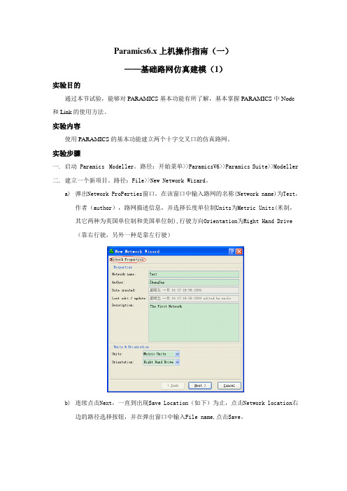
a)弹出Network ProPerties窗口。
在该窗口中输入路网的名称(Network name)为Test,作者(author),路网描述信息,并选择长度单位制Units为Metric Units(米制,其它两种为英国单位制和美国单位制),行驶方向Orientation为Right Hand Drive(靠右行驶,另外一种是靠左行驶)b)连续点击Next,一直到出现Save Location(如下)为止,点击Network location右边的路径选择按钮,并在弹出窗口中输入File name,点击Save。
c)点击Next按钮d)点击Finish按钮,完成路网属性的设置,Paramics界面呈如下左图所示,中间灰黑色部分为仿真区域。
系统默认创建了一条单车道直线道路和两个OD小区(白色方框)的简单路网。
三. 将鼠标放在灰黑色区域,滚动鼠标滑轮放大缩小路网比例,调整到合适比例。
四. 将道路从单车道变为多车道。
用菜单Edit>>Editor Palette(或者快捷键Ctrl+E) 调出编辑面板,如上右图所示。
双击编辑面板的标题栏,将其嵌进仿真区域的右边。
点击编辑面板左下角Junction栏右边的下拉键头,在弹出的菜单中选择Links,激活link状态。
将鼠标移到相应的 link上,按鼠标中键选中该条link(被选中的link变成蓝色)。
MRAS6中文操作手册
V 1.0目录操作须知 (3)仪器介绍 (4)安全通则 (5)密闭微波消解中不适消解的物质 (6)高温下化学物质的安全要点 (6)安装 (7)工具 (7)安装地点 (7)开箱 (8)检查 (8)仪器描述 (9)软件图标和按键指引 (13)创建传统方法 (14)编辑方法 (19)删除方法 (20)运行方法 (21)系统菜单 (25)工具 (25)系统 (25)诊断 (26)功率 (26)红外 (26)压力 (27)升级管理 (27)设置 (28)维护、故障解决及服务 (37)清洁 (37)微波泄漏测试 (37)微波功率测试 (37)温度标定(红外传感器) (40)红外温度传感器的校验 (42)压力标定 (43)升级固件 (43)故障解决指南 (44)规格 (47)保修 (48)操作须知MARS6仪器所使用电源必须具有良好接地,以防电源短路对仪器造成严重伤害。
仪器配备了接地插头,必须插入正常接地的插座中。
如果接地要求不能达到或者怀疑仪器没有正常接地,请咨询电工或者相关认证部门。
如果需要使用延长线,仅适用3插头延长线,并保证插入3插头接地插座。
延长线的标号必须等于或者高于仪器原装线指标。
仪器不应该放置在易受电磁干扰的设备旁边。
仪器应远离磁场,微波泄漏量应小于5 mW/cm 2。
本仪器如果选配有磁力搅拌功能会产生一定的磁场,患有心脏病或体内有心脏起搏器的人员请勿操作使用仪器。
仪器发生问题时,维修应由CEM 公司专业工作人员来完成。
本仪器所通过美国、加拿大、欧共体相关安全标准。
本手册中使用的Teflon 为E.I. DuPont 公司注册商标。
仪器介绍微波加速反应系统(MARS6)是一种应用于消解、萃取、蛋白水解浓缩、干燥、合成等实验室工作的仪器。
它的主要功能是为AA(原子吸收)、ICP(电感耦合等离子发射光谱)和LC(液相色谱)等分析的前处理加速样品反应,缩短处理时间,从而提高工作效率。
MARS 组成:◆磁控管(输出功率:0~1800W±15%,IEC)◆防腐内腔◆排风扇及排气管◆数字化电脑编程,每个程序最高可达5步◆自动转盘◆三个内锁开关和一个检测开关保护仪器在开门时停止微波发射MARS 使用微波能量加热样品。
6+Sigma知识集锦――利用Minitab计算Cp、Cpk

-2
-1
0
1
2
15
连续型——数据非正态
对于数据不符合任何分布的情况,可利用 公式进行计算。
• 以二级半系统上下载2008年12月1日—1月31日SPA-H 板坯熔炼成分中C成分为例。 • 通过分析检验,数据不符合任何分布
16
连续型——数据非正态
统计 ↓ 基本统计量 ↓ 显示描述性 统计
17
连续型——数据非正态
根据需要,我们可 以选取统计量中相 应的项,得出需要 的数据
18
连续型——数据非正态
描述性统计: C 平均值 变量 C N 71 N* 0 平均值 0.09143 标准误 0.00100 标准差 0.00845 最小值 0.07000
σ
下四分位数 0.09000 中位数 0.09000
变量 C
上四分位数 0.10000
输入列和子组的大小。 如果在一个子组中只有一个数据,那么子组大小为 1。
上下规格线
8
连续型——数据正态
P 的过程能力
LSL
过程数据 LSL 0.07 目标 * USL 0.1 样本均值 0.078197 样本 N 66 标准差(组内) 0.00200491 标准差(整体) 0.00279681
USL
99 99 百分比 90 90
99 90
99.9
99
99.9
90 50 百分比
90
百分比
百 分分 比 百比
50
90 50 50 10 11 0.100 0.1 -4
百分比
百分比
50 10 1 0.1
10 1 0.1 0.03 Alt
50
50
10
10
ZETA6xxx 安装指南疑难解惑章说明书

C H A P T E R T W O TroubleshootingIN THIS CHAPTER•Troubleshooting basics:-Reducing electrical noise-Diagnostic LEDs-Test options-Technical support•Solutions to common problems•Resolving serial communication problems•Product return procedureTroubleshooting BasicsWhen your system does not function properly (or as you expect it to operate), the first thingthat you must do is identify and isolate the problem. When you have accomplished this,you can effectively begin to resolve the problem.The first step is to isolate each system component and ensure that each component functionsproperly when it is run independently. You may have to dismantle your system and put it backtogether piece by piece to detect the problem. If you have additional units available, you maywant to exchange them with existing components in your system to help identify the source ofthe problem.Determine if the problem is mechanical, electrical, or software-related. Can you repeat or re-create the problem? Random events may appear to be related, but they are not necessarilycontributing factors to your problem. You may be experiencing more than one problem. Youmust isolate and solve one problem at a time.Log (document) all testing and problem isolation procedures. You may need to review andconsult these notes later. This will also prevent you from duplicating your testing efforts.Once you isolate the problem, refer to the problem solutions contained in this chapter. If theproblem persists, contact your local technical support resource (see Technical Support below). Reducing Electrical NoiseRefer to the guidelines on page 26. General information on reducing electrical noise can befound in the Engineering Reference section of the Parker Compumotor/Digiplan catalog.Appendix D (page 63) provides guidelines on how to install the ZETA6xxx in a manner mostlikely to minimize the ZETA6xxx’s emissions and to maximize the ZETA6xxx’s immunity toexternally generated electromagnetic interference.Diagnostic LEDsPOWER................On (green) if 120VAC (or 240 VAC for 240V versions) connected. Off ifno power.STEP...................Flashes on (green) with each pulse sent to the motor. Off if no pulses.OVER TEMP.........On (red) if internal sensor reaches 122°F (50°C). Off = O.K.MOTOR FAULT.....On (red) if there is a short in the motor windings, if the motor cable isdisconnected or shorted, or if the INTERLOCK jumper on the MOTORconnector is removed or extended. Off = O.K.Test Options•Test Panel. Motion Architect’s Panel Module allows you to set up displays for testingsystem I/O and operating parameters. Refer to the Motion Architect User Guide for details.•Hardware Test Procedure (see pages 27-29).•Motion Test. A test program is available to verify that the ZETA6xxx is sending pulses tothe motor and that the motor is functioning properly. The test program can be initiated byissuing the TEST command over the serial interface, or by accessing the RP240 TESTmenu (see 6000 Series Programmer’s Guide for RP240 menu structure).WARNINGThe TEST program causes the end-of-travel limits to be ignored. If necessary, disconnectthe load to ensure the test moves do not damage your equipment or injure personnel.46ζZETA6xxx Installation GuideTechnical SupportIf you cannot solve your system problems using this documentation, contact your localAutomation Technology Center (ATC) or distributor for assistance. If you need to talk to ourin-house application engineers, please contact us at the numbers listed on the inside cover ofthis manual. (These numbers are also provided when you issue the HELP command.)NOTE: Compumotor maintains a BBS that contains the latest software upgrades and late-breaking product documentation, a FaxBack system, and a tech support email address.Chapter 2. Troubleshooting47Common Problems & SolutionsNOTE: Some software-related causes are provided because it is sometimes difficult to identify a problem as either hardware or software related.Problem Cause SolutionCommunication (serial) not operative, or receive garbled characters.1. Improper interface connections orcommunication protocol.2. COM port disabled.3. In daisy chain or multi-drop, the unitmay not be set to proper address.1. See Troubleshooting Serial Communication section below.2.a. Enable serial communication with the E1 command.2.b. If using RS-485, make sure the internal jumpers are set accordingly(see page 8). Make sure COM 2 port is enabled for sending 6000language commands (execute the PORT2 and DRPCHKØ commands).3. Verify DIP switch settings (see page 7), or proper use of ADDRcommand.Direction is reversed.1. Phase of step motor reversed (motordoes not move in the commandeddirection).2. Phase of encoder reversed (reportedTPE direction is reversed).1. Swap the A+ and A– connection at the MOTOR connector.2. Swap the A+ and A– connection at the ENCODER connector.SOFTWARE ALTERNATIVE: If the motor (and the encoder if one isused) is reversed, you can use the CMDDIR1 command to reverse thepolarity of both the commanded direction and the polarity of the encoderfeedback counts.Distance, velocity, and accel are incorrect as programmed.1. Incorrect resolution setting. 1.a. Set the drive resolution to 25,000 steps/rev (DRES25ØØØ command).1.b. Set the ERES command setting (default setting is 4,000 counts/rev)to match the post-quadrature resolution of the encoder. Compumotorencoders:E Series Encoders ............................................ ERES4000OS motor with -HJ encoder (OSxxx-xxx-HJ) ...... ERES2048OS motor with -RE encoder (OSxxx-xxx-RE) ..... ERES4000OS motor with -RC encoder (OSxxx-xxx-RC) .... ERES4000RS motor with -EC encoder (RSxxx-xxx-EC) ..... ERES4000TS motor with -EC encoder (TSxxx-xxx-EC)*Encoder counts missing.1. Improper wiring.2. Encoder slipping.3. Encoder too hot.4. Electrical noise.5. Encoder frequency too high.1. Check wiring.2. Check and tighten encoder coupling.3. Reduce encoder temperature with heatsink, thermal insulator, etc.4.a. Shield wiring.4.b. Use encoder with differential outputs.5. Peak encoder frequency must be below 1.6MHz post-quadrature.Peak frequency must account for velocity ripple.Erratic operation. 1. Electrical noise and/or impropershielding.2. Improper wiring.1.a. Reduce electrical noise or move ZETA6xxx away from noise source.1.b. Refer to Reducing Electrical Noise on page 46.2. Check wiring for opens, shorts, & mis-wired connections.LEDs See Diagnostic LEDs above (page 46)Motion does not occur.1. Check LEDs.2. End-of-travel limits are active.3. P-CUT (Pulse cut-off) not grounded.4. Drive fault detected.5. Undervoltage (AC supply < 95 VAC).6. Improper wiring.7. Load is jammed.8. No torque from motor.1. See Diagnostic LEDs above.2.a. Move load off of limits or disable limits with the LHØ command.2.b. Set LSPOS to a value greater than LSNEG.3. Ground the P-CUT connection.4. Check status with TASXF command (see bit #4).5. Check status with TASXF command (see bit #2). Check AC supply.6. Check motor and end-of-travel limit connections.7. Remove power and clear jam.8. See problem: Torque, loss of.Motor creeps at slow velocity in encoder mode (ENC1).1. Encoder direction opposite of motordirection.2. Encoder connected to wrong axis.1. Switch encoder connections A+ & A- with B+ & B-.2. Check encoder wiring.Programmable inputs not working.1. IN-P (input pull-up) not connected toa power supply.2. If external power supply is used, thegrounds must be connected together.3. Improper wiring.1.a. When inputs will be pulled down to 0V by an external device, connectIN-P to +5V supplied or to an external 5-24V positive supply (but not toboth).1b. When inputs are pulled to 5-24V by an external device, connect IN-Pto 0V.2. Connect external power supply's ground to ZETA6xxx’s ground (GND).3. Check wiring for opens, shorts, and mis-wired connections.48ζZETA6xxx Installation GuideProgrammable outputs not working.1. Output connected such that it mustsource current (pull to positive voltage).2. OUT-P not connected to powersource.3. If external power supply is used, thegrounds must be connected together.4. Improper wiring.1. Outputs are open-collector and can only sink current -- change wiring.2. Connect OUT-P to the +5V terminal or to an external supply of up to24V.3. Connect the external power supply’s ground to the ZETA6xxx’s ground(GND).4. Check wiring for opens, shorts, and mis-wired connections.Torque, loss of. 1. Improper wiring.2. No power (POWER LED off).3. Overtemp, low voltage, or motorfault.4. Drive shutdown.5. Current standby mode enabled.1. Check wiring to the motor, as well as other system wiring.2. Check power connection (POWER LED should be on).3. Check LED status (see Diagnostic LEDs above).4. Enable drive with the DRIVE1 command.5. If more torque is needed at rest, disable standby mode (DAUTOSØcommand).Trigger, home, end-of-travel, or P-CUT inputs not working.1. If external power supply is used, thegrounds must be connected together.2. Improper wiring.1. Connect external power supply’s ground to ZETA6xxx’s ground (GND).2.a. Check wiring for opens, shorts, and mis-wired connections.2.b. When inputs are pulled down to 0V by an external device, connectAUX-P to +5V supplied or to an external +5-24V supply (but not to both).2.c. When inputs are pulled to 5-24V by external device, connect AUX-Pto 0V.2.d. Make sure a 5-24V power source is connected to the V_I/O terminal.* Not released as of this printing.Chapter 2. Troubleshooting49Troubleshooting Serial Communication ProblemsGeneral Notes•Power up your computer or terminal BEFORE you power up the ZETA6xxx.•Make sure the serial interface is connected as instructed on page 12. Shield the cable to earthground at one end only. The maximum RS-232 cable length is 50 feet (15.25 meters).•RS-232: Handshaking must be disabled. Most software packages allow you to do this. Youcan also disable handshaking by jumpering some terminals on the computer’s/ terminal’sserial port: connect RTS to CTS (usually pins 4 and 5) and connect DSR to DTR (usuallypins 6 and 20).•RS-485: Make sure the internal DIP switches and jumpers are configured as instructed onpage 8.1.Power up the computer or terminal and launch the terminal emulator.Test the Interface2.Power up the ZETA6xxx. A power-up message (similar to the following) should be displayed,followed by a prompt (>):∗PARKER COMPUMOTOR 6000 Series – SINGLE AXIS INDEXER/DRIVE∗RP240 CONNECTED>3.Type “TREV” and press the ENTER key. (The TREV command reports the software revision.)The screen should now look as follows (if not, see Problem/Remedy table below).∗PARKER COMPUMOTOR 6000 Series – SINGLE AXIS INDEXER/DRIVE∗RP240 CONNECTED>TREV∗TREV92-014630-01-4.7250ζZETA6xxx Installation GuideProblem Remedy (based on the possible causes)No Response•COM port not enabled for 6000 language communication.If RS-232 connected to COM 1: issue “PORT1” and “DRPCHKØ” commands.If RS-232 connected to COM 2: issue “PORT2” and “DRPCHKØ” commands.If RS-485 connected to COM 2: issue “PORT2” and “DRPCHKØ” commands.•RS-232: Echo may be disabled; enable with the ECHO1 command.•If you are using an RS-232 connection between the host computer and themaster ZETA6xxx connected to multiple ZETA6xxxs in an RS-485 multi-drop,make sure the master ZETA6xxx has these settings executed in the ordergiven (you should place these settings in your power-up STARTP program):PORT1(select RS-232 port, COM1, for configuration)ECHO3(echo to both COM ports)PORT2(select RS-485 port, COM2, for configuration)ECHO2(echo to the other COM port, COM1)•Faulty wiring. See instructions on page 12. RS-485: verify internal DIPswitch and jumper settings on page 8. Also check for shorts or opens.•Is the cable or computer/terminal bad? Here’s a test:1.Disconnect the serial cable from the ZETA6xxx end only.2.Connect the cable’s Rx and Tx lines together (this echoes the charactersback to the host).3.Issue the TREV command. If nothing happens, the cable orcomputer/terminal may be faulty.•The controller may be executing a program. Issue the !K command or the<ctrl>K command to kill the program.Garbled Characters •Verify setup: 9600 baud (range is 19200-1200—see AutoBaud, page 7),8 data bits, 1 stop bit, no parity; RS-232: Full duplex; RS-485: Half duplex(change internal jumper JU6 to position 1).•RS-485: Transmission line not properly terminated. See page 8 for internal DIP switch and jumper settings. See page 12 for connections andcalculating termination resistors (if not using the internal resistors via internal DIP switches).•Faulty wiring. See instructions on page 12. RS-485: verify internal DIP switch and jumper settings on page 8. Also check for shorts or opens.Double Characters•Your terminal emulator is set to half-duplex; set it to full-duplex.Chapter 2. Troubleshooting51Product Return ProcedureStep 1Obtain the serial number and the model number of the defective unit, and secure a purchase order number to cover repair costs in the event the unit is determined by the manufacturers to be out of warranty.Step 2Before you return the unit, have someone from your organization with a technical understanding of the ZETA6xxx system and its application include answers to the following questions:•Which version of the ZETAxxx do you have?•What is the extent of the failure/reason for return?•How long did it operate?•Did any other items fail at the same time?•What was happening when the unit failed (e.g., installing the unit, cycling power, starting otherequipment, etc.)?•How was the product configured (in detail)?•Which, if any, cables were modified and how?•With what equipment is the unit interfaced?•What was the application?•What was the system environment (temperature, enclosure, spacing, contaminants, etc.)?•What upgrades, if any, are required (hardware, software, user guide)?Step 3Call for return authorization. Refer to the Technical Assistance phone numbers provided on the inside front cover of this document. The support personnel will also provide shipping guidelines.52ζZETA6xxx Installation Guide。
S-Paramics软件简易教程
8.加载demand 在相应道路起点增加zone,通过屏幕上方的editdemands-demand type进行OD矩阵的加载,可以通过 excel进行大规模OD矩阵的加载。同时可以进行OD矩阵 的相应设置。 9.进行仿真 使用空格键可以快速开始仿真。 这样,一个简易的S-Paramics模型就完成了,接下来, 我们要花大量的时间进行模型的细化,使其与真实的交 通情境达成近似一致。当交通模型完善后,我们就可以 通过DAT工具获得我们想要的交通数据了。
本实例以崔师兄博士论文中提到的案例作为基础(感谢 @崔建勋博士论文提供相应路网数据与OD需求) 1.建立模型 在建立模型之前,一定要确定系统的操作语言是英语 (英国),否则将会导致无法导入底图等情况出现,切 记! 点击S-Paramics菜单中的SPX的New Model,在文件夹路 径后输入模型名称,如C:\.paramics\data\changchun0513, 而后进行naming等设置,然后点击OK。
location中输入CAD图相关子路径,如../overlays/1.dxf。 在保存时可能出现bug,点击屏幕左下角的editorinclude&save即可解除。
3.建立node 以导入的底图为基础,选择屏幕左下角的editor-node,在底 图节点处通过add node建立节点。 4.建立link 选择屏幕左下角的editor-node,然后中间键选择一个node, 右键选择另一个node,通过add link增加link。注意,进行 include&save操作后才能显示刚建立的link。可以通过editlink进行link的更改操作。曲线则通过link设置为arc后,在 curve中编辑。 5.建立zone 选择屏幕左下角的editor-zone,调整屏幕的视角后,选取合 适位置通过add zone建立一个新zone
ParamEditor软件使用说明
ZS-8848光纤熔接机用户手册(附件)ParamEditor(参数编辑器)软件使用说明2014年2月中国四川灼识科技股份有限公司二软件下载一软件下载1.1 请您登录四川灼识科技股份有限公司官方网站:/进入网站页面,点击“技术与支持”1.2 选择“资料下载”1.3 请您点击选择名为的文件,选择“下载”并保存在您的电脑中1.4 右键点击并解压到当前文件夹1.5 用随机配带的数据线把熔接机USB端口和您的电脑连接,熔接机开机1.6 双击打开文件夹1.7 点击图标。
电脑会自动安装并运行该软件,您的电脑会打开如右图所示的窗口:祝贺您!下面您就可以进行更换电极和熔接机参数修改了。
二电极更换二电极更换当需要更换电极时,熔接机会有间断蜂鸣声提醒你;如果电极寿命达到极限,熔接机会有长时间蜂鸣声,并自动关闭程序。
电极更换必须使用专为本机设计的正规原厂电极。
当电极使用次数达到极限时,应及时更换电极,否则可能会影响接续质量。
甚至自动关闭程序,不能进行熔接。
电极更换步骤如下:a)电极更换必须在关机的情况下进行。
放电时,电极上有数千伏的高压,会对人身造成较大伤害;b)打开防尘罩,即可看见电极,其结构示意参见《操作手册》第五章图5-2所示;c)先拧松“电极压条”螺钉,将“电极”用镊子夹住,再拧掉“螺钉”,取出“电极压条”,拿出“电极”。
注意不要让“电极”掉入熔接机中。
将新“电极”放入电极座槽,同时将“电极压条”插入“固定座”,再拧上螺钉,将“电极”向前推到底,再拧紧“螺钉”即可;d)更换另一个电极;e) 用数据线连接熔接机和电脑,将熔接机开机。
打开电脑中名为的软件,点击“设备管理”选择“连接设备”;f) 打开“更换电极”页,输入电极编号,点“获取本机设备编号”,获得本机设备编号。
如果你正在使用的电脑已联网,则可以点击“从网络获取”获得激活码。
否则用其它方式登录网页(/check),输入电极编号和设备编号来获取激活码。
g)输入激活码后,点击“校验激活”。
hyperMILL 5-axis训练手册
h y p e r M I L L5-a x i s训练手册------------------------------------------作者xxxx------------------------------------------日期xxxxhyperMILL 5-Axis 課程五軸加工的應用五軸機器的型式決定5-AXIS加工品質的因素?●床台的旋轉精度●控制器認知的機械旋轉中心位置(無RTCP時則為機器旋轉中心的補正中心) ●刀把的動平衡●球刀的研磨精度●刀長量測精度●加工的程序控制器的優勢--什麼是RTCP●RTCP在Sinumerik840D控制器上的指令為”TRAORI”●RTCP在HeidenhainiTNC530控制器上的指令為”M128”●RTCP在Fanuc16i控制器上的指令為”G”在以前控制器還不支援RTCP的功能,軟體又不支援補正時,往往必須製作輔助治具,將工件一直固定在旋轉中心上,到現在大部分的4-axis還是用這個方式加工,進而在軟體支援補正功能後,工件可以任意的偏置,但是軟體計算完刀具路徑後,也不能預先轉換NC檔案,必須將加工件架上床台後,量測工件上的加工基準位置與機床旋轉中心位置的差值,將該數值輸入至post後,靠post運算出新的座標位置後方能產生正確的NC程式,演變至近來控制器提供了RTCP的功能後,加工製作的方式就像是3軸加工一樣的簡單了,因為控制器知道了機台旋轉中心的位置,NC程式中只要輸出與工件上基準位置相對的座標,而控制器會自動計算該座標和旋轉中心的關係,進一步補正出新的位置,因為不需要靠post的計算,因此當軟體計算完刀具路徑後,直接即可轉換NC檔案輸出至機器了.如果控制器沒有RTCP的功能處置方式如下:1.將工件架設置工作台,不需要一定得放置於旋轉中心.2.量測工件上的基準中心點的XY值和C軸旋轉中心的差值.3.量測工件上的基準中心點的Z值和A軸旋轉中心的差值.4.將差值填入軟體程式後處裡的機器定義表格如下圖.5.進行post處理後,即產生補正後新座標的NC程式.控制器的優勢什麼是Tile Plane主要是應用在定位加工時,定位加工(Indexing)和3+2軸加工的不同如何進行定位加工如何進行3+2軸加工5-axis 鑽孔加工5-axis 外形輪廓加工5-axis 側面加工5-axis 頂面加工5-axis模具加工工法(自動)及模具加工工法介紹5-axis模具加工工法(自動) with Indexing5-axis模具加工工法(進階)5-axis 自動定位加工5-axis路徑再加工將2D/3D路徑加入刀軸傾擺5-axis路徑再加工將5X加工路徑變更刀軸傾擺5-axis路徑再加工將5X加工路徑保持刀軸傾擺改變刀具路徑5-axis 葉輪加工模組Post的調整。
ELATION PROFESSIONAL SIXPAR 300 用户手册说明书
N | SIXPAR 300™ | user manualSIXPAR 300™user manualw w w. e l a t i o n l i g h t i n g . c o m©2019 ELATIONdiagrams,ELATION PROFESSIONALare trademarks of ELATION PROFESSIONAL.all forms andstatutory ordocumentcompanies and are hereby acknowledged.names are trademarks or registered trademarks of their respective companies.C O N T E N TGeneral InformationG E N E R A LINTRODUCTIONCongratulations,reliablebeen designedWARRANTY REGISTRATIONPlease fill out the enclosed warranty card to validate your purchase. All returned serviceaccompanyclearlyproblempaper and included in the shipping container. If the unit is under warranty, youL I M I T E D W A R R A N TA. Elationbe free of manufacturing defectsand Elation Professional® pmaterial andThis warranty if the productS A F E T YDIRECTL Y WITH OPTICAL INSTRUMENTSINDIVIDUALS SUFFERING FROM A RANGE OF EYE CONDITIONS, INDIVIDUALS U S I N G PHOTOSENSITIVE MEDICATION, ULTRAVIOLET UV LIGHT EMITTED FROM THE UV LED.IMPORTANT NOTICE!There arey o u r s eresultinggeneralG E N E R A LN E V E R•During the initial operation of this fixture, a light smoke or smell may emit from the interior of the fixture. This is a normal process and is caused by excess paint in the interior of the casing burning off from the heat associated with the lamp and willF I X T U R Ew w w. e l a t i o n l i g h t i n g . c o m F I X T U R E I N S T A L L A T I OMOUNTING POINTS•Overhead mounting requires extensive experience, including amongst others calculating working load limits, installation material being used, and periodic safety inspection of all installation material and the device. If you lack these qualifications, do not attempt the installation yourself. Improper installation can result in bodily injury.S A F E T Y C A B L EAlways use a Safety Cable whenever installing this fixture in a suspendedenvironment to ensure the fixture will not drop if the clamp fails.U N D E R S T A N D I N GDMX-512DMX is short for Digital Multiplex. This is a universal protocol used by most lighting and controllerand controllers. DMX allows all makes and models of different manufactures to be linked together and operate from a single controller. This is possible as long as all thew w w. e l a t i o n l i g h t i n g . c o mDMX-512 CONTROLLER CONNECTIONConnect the provided XLR cable to the female XLR output of your controller and the other side to the male XLR input of thetypical DMX-512chain multiple panels together through serial linking. Always be sure daisy chain your in and out data connections, never split or “Y” your DMX connections.DMX ADDRESSINGAll fixtures should be given a DMX starting address when using a DMX controller, so the correct fixture responds to the correct control signal. This digital starting address is the channel number from which the fixture starts to “listen” to the digital control informationaddress isF I X T U R E M E NON-BOARD SYSTEM MENUThe SIXPAR 300™will cover how to access each menu function.LCD CONTROL PANEL DISPLAYINFORMATION DISPLAYED DURING INITIAL POWER ONWhen the fixture is initially powered ON, the display shows the following information:LCD CONTROL PANEL LOCKOUTWhen AutoLockand the Control Panel will lock and the display will show Press and hold theWhen AutoLockand theTo unlock the Control Panel, follow these steps:DIMMING CURVESThe DimCurveStandard, Stage, TV, Architec,DimmerD M XMODE / CHANNEL6 CH7 CHMODE / CHANNEL6 CH7 CHMODE / CHANNEL 6 CH7 CHC L E A N I N GT E C H N I C A LFEATURES15° Beam 25° Field Angles5 Variable Dimming Curve Modes Dual Yoke / Floor StandMultiple Unit Power LinkingRDM - Remote Device Management Rugged Die-Cast Aluminum Exterior Flicker Free Operation for TV and FILMPlease Note: SpecificationsPHOTOMETRIC DATADIMENSIONAL DRAWINGSO P T I O N A LORDER CODETRIGGER CLAMPSIXPAR300/GFHSIXPAR/BD300。
- 1、下载文档前请自行甄别文档内容的完整性,平台不提供额外的编辑、内容补充、找答案等附加服务。
- 2、"仅部分预览"的文档,不可在线预览部分如存在完整性等问题,可反馈申请退款(可完整预览的文档不适用该条件!)。
- 3、如文档侵犯您的权益,请联系客服反馈,我们会尽快为您处理(人工客服工作时间:9:00-18:30)。
Paramics6.x上机操作指南(五)
——交叉口仿真建模(5)
实验目的
通过本节试验,能够掌握kerb的基本操作,以及右转专用道的设置方法。
实验内容
将上节实验中十字交叉口南进口的一条车道设置为右转专用道。
实验步骤
一. 启动 Paramics Modeller,打开路网目录下的Intersection_Demo路网,方法
File>>Open,路径缺省。
三、在3号节点以南150米处新建节点Node称为A点(方法:Split link3:8,修改A点Y 坐标为-150)。
将新增加节点A与3号节点之间的北行方向路段设置为3车道,12米宽。
同样在3号节点以东150米处新建节点Node称为B点(方法:Split link3:4,修改B点X坐标为-100)。
将3点与新增节点B之间的东行方向路段设置为3车道、12米宽。
如下图所示。
四、在A点处右侧建立一个C点,在A、C点之间新建一条单向link。
单向linkA:C建立
方法:切换到Link模式,鼠标中间点击A点(起点),鼠标右键点击C点(终点),钩选编辑面板下部的One way复选框(如下图所示),点击Add new按钮,Save Changes。
五、鼠标中键点击选中C点,按住shift键,用鼠标中键拖动上图中的C点,使其尽可能接近道路边沿,Save Changes。
如下图所示:
六、将编辑面板切换到Control Points模式。
可以看到任意link的四个角都变成了四个空心小正方形,这些正方形就是kerb points。
用鼠标中键点击选中其中一个kerb points,选中呈实心状态,按住Shift键,用鼠标中键拖动其位置,使得最终四个点的位置如右图所示形式,Save Changes,。
Kerb points修改之前修改之后效果图
七、添加单向linkAC的下游link,其属性为1车道,单向(one-way)。
按照上述方法修改该link的kerb points,如下图所示:
八、按照第六、七步的方法对6号节点东出口道的B点进行类似的操作,得到结果如下图所示:
九、用一条单向link连接E、F两点(注意方向不能相反),其属性为1车道,Save Changes。
十、将编辑面板切换到Control Points模式,选择Arcs选项卡,鼠标中键选中linkE:F,点
击选中Arc Right项,Save Changes,生成一条狐型道路。
十、修改LinkE:F的弧度(方法参考指南三),使得它与两端的link都自然衔接,如下:
十二、点击Simulate>>Start开始仿真,观察车辆在右转专用道特别是节点处的驾驶行为是否正常。
假如不正常——一般都不正常,需要对车辆在节点处的驾驶行为进行调整。
十一、将编辑面板切换到Control Points模式,选择Stoplines选项卡。
选择Edit position项,
此时缩小路网比例,可以清楚看到所有的节点处,每条车道都出现了一对白色和红色的箭头,
其中白色箭头代表进入节点,红色箭头代表离开节点,所以白色箭头一定要在红色箭头之前。
这些箭头代表了车辆在经过节点的车头方向。
鼠标中键点击选中所要调节的箭头,选择Edit Position项,按住Shift键,用鼠标中键拖动箭头可对箭头的位置进行调节;选择Edit rotation 项,按住Shift键,用鼠标中键拖动箭头可对箭头的方向进行调节。
最终结果如下所示:
南进口道
东出口道。