F式说明书
离心风机说明书

目录1.风机的用途及适用范围.............................................................................. 错误!未定义书签。
2. 风机的结构形式............................................. 错误!未定义书签。
3. 风机的安装、调整和试运转(分别为D式、F式)............... 错误!未定义书签。
4. 风机的运行................................................. 错误!未定义书签。
5. 风机的维护................................................. 错误!未定义书签。
6. 风机成套供货范围(一台)................................... 错误!未定义书签。
7. 订货需知(需提供下列资料)................................. 错误!未定义书签。
8. 备件订货说明............................................... 错误!未定义书签。
表一:经常或定期检查项目 ................................ 错误!未定义书签。
表二:运行时每3—6个月检查的项目 ....................... 错误!未定义书签。
表三:风机的主要故障及排除方法 .......................... 错误!未定义书签。
表四:轴承振动允许值 .................................... 错误!未定义书签。
附图I ................................................... 错误!未定义书签。
爱森F-框型固定热敏式电路保护器说明书

Eaton FD3015VSH09Eaton Series C complete molded case circuit breaker, F-frame, FD, Fixed thermal, fixed magnetic trip, Three-pole, 15A, 600 Vac, 250 Vdc, 65 kAIC at 240 Vac, 35 kAIC at 480 Vac, Stainless steel, Load side, Naval, 50°C, 50/60 HzGeneral specificationsEaton Series C complete molded case circuit breakerFD3015VSH097866790255053.38 in 6 in4.13 in 4.5 lb Eaton Selling Policy 25-000, one (1) year from the date of installation of the Product or eighteen (18) months from the date of shipment of the Product, whichever occurs first.UL 489Product NameCatalog Number UPCProduct Length/Depth Product Height Product Width Product Weight WarrantyCertifications35 kAIC at 480 Vac65 kAIC at 240 VacF50°C15 AThree-poleSeries CFD50/60 HzNavalComplete breakerLoad side600 Vac, 250 VdcStainless steelFixed thermal, fixed magnetic Application of Tap Rules to Molded Case Breaker TerminalsUL listed 100%-rated molded case circuit breakersApplication of Multi-Wire Terminals for Molded Case Circuit BreakersStrandAble terminals product aidCurrent limiting Series C molded case circuit breakers product aidMotor protection circuit breakers product aidCircuit breaker motor operators product aidMulti-wire lugs product aidMOEM MCCB Product Selection GuidePlug-in adapters for molded case circuit breakers product aidPower metering and monitoring with Modbus RTU product aid Counterfeit and Gray Market Awareness GuideBreaker service centersMolded case circuit breakers catalogEaton's Volume 4—Circuit ProtectionTime Current Curves for Series C® F-Frame Circuit BreakersInstallation Instructions for EHD, EDB, EDS, ED, EDH, EDC, FDB, FD, HFD, FDC, HFDDC Circuit Breakers and Molded Case SwitchesCircuit breakers explainedCircuit Breakers ExplainedEaton Specification Sheet - FD3015VSH09Series C J-Frame molded case circuit breakers time current curves Series C G-Frame molded case circuit breakers time current curves MOEM MCCB product selection guideSeries C F-Frame molded case circuit breakersInterrupt ratingFrameCalibrationAmperage Rating Number of polesSeriesCircuit breaker type Frequency ratingClassCircuit breaker frame type TerminalsVoltage ratingTerminal materialTrip Type Application notesBrochuresCatalogsDrawingsInstallation instructions MultimediaSpecifications and datasheetsEaton Corporation plc Eaton House30 Pembroke Road Dublin 4, Ireland © 2023 Eaton. All Rights Reserved. Eaton is a registered trademark.All other trademarks areproperty of their respectiveowners./socialmedia。
科裕F指纹锁产品使用说明书

科裕指纹锁918-6-F系列使用说明书-中文科裕集团(旗下)江门市科裕智能科技有限公司版权所有侵权必究1、简介门锁简介欢迎您选用本公司的智能指纹门锁,本门锁具有强大的管理功能,可同时支持指纹、密码及钥匙开锁操作,指纹及密码都有级别区分,分为管理员与普通用户级别,管理员级别除了可开锁外还可用于“增加用户”及“删除用户”操作。
本门锁支持110个用户,分别为5个管理员密码、5枚管理员指纹,50个普通用户密码、50枚普通用户指纹。
本门锁工作电压为6V,可由2节AA电池供电。
门锁部件图门锁设置流程:门锁安装后需进行相关的设置后方可正常使用,设置流程如下:门锁初始化又叫全清或工厂复位。
执行该操作后,门锁内所有的指纹、密码等信息将被清空,清空后门锁自动生成一个出厂密码“”。
该密码用于临时开锁操作以及设置门锁的管理员,一旦设置了门锁的管理员,此密码将失效。
操作流程:在后面板,打开电池盒盖,使用细小的工具从下图箭头指示的地方(RESET键)插入,抵住按钮并往下压按,直至听到“嘀”一声后放开。
管理员是门锁的一类特殊的用户,主要用于管理门锁之用,具有较高的级别,除了可以开、关门锁外,还可增加、删除用户;增加或删除用户前必须验证管理员权限;门锁清空后必须先设置好至少一个管理员后才能设置普通用户,管理员可以是指纹也可以是密码。
登记管理员指纹或密码操作流程:注:➢确定门锁的管理人后,请选择其纹路清晰的手指登记为管理员指纹。
➢对于初次登记管理员时,由于门锁为清空状态,没有管理员用户,所以在第2步时请输入“出厂密码”:(输完密码后按“#”键结束)。
➢本门锁登记指纹时需连续采集两次,当第一次采集成功后,一定要移开手指约1秒,然后再按下相同的手指,否则登记不成功。
➢输入密码时,密码长度为3~12位,若密码不足12位应以“#”键结束。
➢对于指纹门锁,密码是一种辅助方式,仅在指纹无法正常读取或无法识别时使用。
➢为确保门锁的安全性,密码设置要求在便于记忆的同时应尽量长一些。
F490A 压力计使用说明书中文版

数字指示计
01FEB2012REV.1.00
简介
非常感谢您购买我公司的 F490A 数字指示计。为了充分发挥 F490A 数字指示计的优异性能并保证您的 使用安全,在使用之前请您仔细阅读本操作手册并正确理解其内容。此外,请精心保存本操作手册,以 便可以随时取阅。
使用注意事项和要求
● 电源 ·对于外部电源,请使用专用交流适配器(可选用)。 如果使用了专用交流适配器以外的任何外部电源,本公司将不提供任何保证。 ·在使用电池的情况下,F490A使用4节AA碱性电池或镍氢电池工作。 请按正确的正负极方向插入电池。
● 请勿用湿手触摸F490A,或向其上溅水。
● 这样做可能会引起火灾或触电事故。
● 对于外部电源,切勿使用专用交流适配器以外的其他部件。这样做可能会引起火灾。
● 不要在F490A数字指示计的开口插入或落入金属或易燃材料等异物,否则可能会引起火灾、触电事故 或故障。
● 切勿拆解或改装F490A数字指示计,否则可能会引起火灾、触电事故或故障。 (本公司对拆解或改装过的设备不予受理。)
■ 功能设置 0 .......................................................................................................... 9 ■ 功能设置 1 .......................................................................................................... 9 ■ 功能设置 2 .......................................................................................................... 9 ■ 模式设置............................................................................................................10 ■ 保持功能............................................................................................................10 ■ 图形功能............................................................................................................10 3-3. 屏幕配置 ................................................................ 11 3-4. 每个画面的解释和按键操作 ................................................ 12 ■ 主画面 ...............................................................................................................12 ■ 设置画面 ..........................................................................................................15 ■ 模式设置............................................................................................................16 ■ 功能设置 1/功能设置 2.......................................................................................16
离心式通风机D、F型
上虞专用风机有限公司D、F 式系列离心风机使用说明书目一.产品简介1.结构特点 2.使用范围 3.附图录二.使用说明1.用户收货检验的程序 2.安装前的贮存和保管 3.风机安装前的重要技术准备 4.安装风机及调整程序 5.使用运转的程序 6.制造厂重要提要:绝对禁止的错误操作项目 7.风机使用中的故障及排除2上虞专用风机有限公司D、F 式系列离心风机使用说明书一.产品简介D、F 型(联轴器传动型)离心通风机可作为各行各业的通风、引风、换气用, 同时也适用于大型锅炉送引风, 钢铁厂冶炼除尘设备。
如输送气体有其它具体变化时, 可制作成特殊材料风机。
1.结构特点(参见附图一,以 D 型结构为例) 此型风机的组成部分主要由:叶轮组、机壳、进风口、联轴器、进气箱(F 式)等部 件配电机而组成。
1.1 叶轮由前盘、后盘及叶片组成。
由轮毂联接上主轴,通过联轴器与电机传动。
因用户使用条件的不同而选用不同的材质;通常用钢板、铸铝合金或高强度的低合金 钢。
使用于含腐蚀性介质的场合则应选用特殊不锈钢。
1.2 机壳为整体式或可剖分拆开,机壳用钢板制作成蜗形体,根据用户的需要, 可设有排水口,清灰门,大型的机号可设置人孔门。
1.3 集流器(俗称进风口) ,一般为整体式,轴向剖面为曲线形状(呈喇叭口型) , 能使介质以最低的阻损流线通过。
1.4 联轴器起到把电机的扭矩传给主轴的叶轮。
1.5 进气箱(F 式)为矩型,整体呈收敛型,用底部支撑架固定在基础上,外壁面 有网状筋板以增强刚性。
3上虞专用风机有限公司D、F 式系列离心风机使用说明书附图一(D 型结构)2.风机的重要结构要素 2.1 旋向:顺、逆旋向的判断。
从电动机一侧正视,叶轮顺时针旋转的,称为右 旋,以“右”表示;叶轮逆时针旋转的,称为左旋,以“左”表示。
2.2 出口角:以机壳的出风口角度表示。
按风机行业的标准,一般由 0°、45°、 90°、135°、180°、225°、275°、315°,如用户对设备安装角度有特殊要求,订 货时需注明。
美嘉欣 F-SERIES2.4G 遥控直升机 说明书

半径5000米的区域内使用各类模型遥控器。在国家有关部门发布无线电管制 命令期间,区域内,应该按要求停止使用模型遥控器。
7
电源开关
控制遥控器的电源,拔到“ON”时,为接通遥控器 电源,拔到“OFF”时,为遥控器断开电源。
3
序号 8
功能键及名称 遥控天线
作
用
发送遥控器无线控制信号
(1)指示灯断续闪烁:表示遥控器还没有启动,需将
油门左操纵杆向上推到最高端,再拉到最低端后
才可启动遥控器。
9
状态指示灯 (2)指示灯一直不停快速闪:表示遥控器处于对码状
(2配)件能图执行上升/下降,左/右转向,左/右侧飞,前进/后退,航线飞行等动作。
(3) 遥控器可根据操纵者的习惯,自行进行左/右手油门切换。
5.2遥控器功能介绍:
8.遥控天线
9.状态指示灯
7.电源开关 1.左操纵遥杆
11.摄像开关键
12.油门模式切换左键
3.微调键A 4.微调键B
6.微调键D
POWER
零件名称
用量 序号
零件名称
用量
1
001 平衡杆组件 1 014 主电机组件 1 027 下牙轮铜套 1 040 左舵机加强铝片 1
002 连接扣
1 015 舵机连接杆组件 2 028
接收板 1 041 尾架斜管固定件 1
003 包注轴组件 1 016 右舵机加强铝片 1 029 主机架底板 1 042 尾架斜管 2
F-Series 压力开关说明书
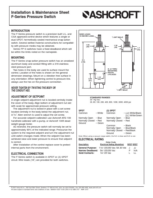
INTRODUCTIONThe F-Series pressure switch is a precision built U.L.and CSA approved control device which features a single or dual SPDT, hermetically sealed mechanical snap-action switch.Several wetted material constructions for compatibil-ity with pressure media may be obtained.Series FP-S switches have a fixed deadband which will be within the limits noted on the nameplate.MOUNTINGThe F-Series snap-action pressure switch has an anodized aluminum body and conduit fitting with a 316 stainless steel pressure port.T wo holes in the body are used to surface mount the control.Location of the holes is shown on the general dimension drawings.Mount on a vibration free surface in any orientation.When tightening control to pressure line, always use the hex on the pressure connection.NEVER TIGHTEN BY TWISTING THE BODY ORTHE CONDUIT HEX.ADJUSTMENT OF SETPOINTA single setpoint adjustment nut is located centrally inside the cover of the body.Align bottom of adjustment nut slot with scale for approximate pressure setting.The adjustment nut is locked in place with a set screw located centrally in the body below the adjustment nut.A5⁄64˝Allen wrench is used to adjust the set screw.For accurate setpoint calibration use Ashcroft A TE-100 handheld calibrator with a pump, or Ashcroft 1305 dead-weight gauge tester.As received, the pressure switch will normally be set to approximately 90% of the indicated range.Pressurize the system to the required setpoint and turn the adjustment nut until switch changes mode.When the setpoint has been achieved raise and lower pressure to ensure that setpoint is correct.After installation of the control replace cover to protect internal parts from the environment.ELECTRICAL CONNECTIONThe F-Series switch is available in SPDT or (2) SPDT circuit.Wire leads (18˝) are provided for both switches.STANDARD RANGES30˝ Hg Vac.30, 60, 100, 200, 400, 600, 1000, 3000, 4000 psiSPDT(2) SPDTCommon–White Common–(JJ)White/Black;(LL) White/Green Normally Open– Blue Normally Open– BlueNormally Closed– Red Normally Closed– RedGround– GreenCommon– BlackNormally Open– Blue/BlackNormally Closed– Red/BlackGround– GreenNote:When using a vacuum range switch, the N.C.is blue and N.O.is red. ELECTRICAL RATINGOrder CodeDescription Electrical Rating (Resistive)SPDT DPDT General Purpose:11A 125/250 Vac;5A 30 Vdc J JJ Narrow Deadband:5A 125/250 Vac P N/A Gold Contacts:1A 125 Vac L LL©2007 Ashcroft Inc., 250 East Main Street, Stratford, CT 06614-5145, USA, T el:203-378-8281, Fax:203-385-0499, All sales subject to standard terms and conditions of sale.I&M009-10027-10/00 (250-3112) GBE 2/07 AMR 12/07。
FortiGate 100F系列产品说明书

FortiGate ® 100F SeriesFG-100F and FG-101FThe FortiGate 100F series provides an application-centric, scalable, and secure SD-WAN solution with Next Generation Firewall (NGFW) capabilities for mid-sized to large enterprises deployed at the campus or branch level. Protects against cyber threats with system-on-a-chip acceleration and industry-leading secure SD-WAN in a simple, affordable, and easy to deploy solution. Fortinet’s Security-Driven Networking approach provides tight integration of the network to the new generation of security.NGFW Threat ProtectionInterfaces20 Gbps 2.6 Gbps 1.6 Gbps 1 GbpsMultiple GE RJ45, GE SFP and 10 GE SFP+ slotsRefer to specification table for detailsSecurity n Identifies thousands of applications inside network traffic for deep inspection and granular policy enforcementn Protects against malware, exploits, and maliciouswebsites in both encrypted and non-encrypted traffic n Prevent and detect against known and unknown attacksusing continuous threat intelligence from AI-powered FortiGuard Labs security servicesPerformancen Delivers industry’s best threat protection performance and ultra-low latency using purpose-built security processor (SPU) technologyn Provides industry-leading performance and protection forSSL encrypted trafficCertificationn Independently tested and validated best security effectiveness and performancen Received unparalleled third-party certifications from NSSLabsNetworkingn Delivers advanced networking capabilities that seamlessly integrate with advanced layer 7 security and virtual domains (VDOMs) to offer extensive deployment flexibility, multi-tenancy and effective utilization of resourcesn Delivers high-density, flexible combination of varioushigh-speed interfaces to enable best TCO for customersfor data center and WAN deploymentsManagement n Includes a management console that is effective, simple to use, and provides comprehensive network automation and visibility.n Provides Zero Touch Integration with Security Fabric’sSingle Pane of Glass Managementn Predefined compliance checklist analyzes the deploymentand highlights best practices to improve overall securitypostureSecurity Fabric n Enables Fortinet and Fabric-ready partners’ products to provide broader visibility, integrated end-to-end detection, threat intelligence sharing, and automated remediationNext Generation Firewall Secure SD-WANSecure Web GatewayDATA SHEETDATA SHEET | FortiGate® 100F SeriesDEPLOYMENTN ext Generation Firewall (NGFW)§Reduce the complexity and maximize your ROI by integrating threatprotection security capabilities into a single high-performance network security appliance, powered by Fortinet’s Security Processing Unit (SPU) §Full visibility into users, devices, and applications across the entire attack surface, and consistent security policy enforcement irrespective of asset location §Protect against network exploitable vulnerabilities with industry-validated IPS that offers low latency and optimized network performance §Automatically block threats ondecrypted traffic using the industry’s highest SSL inspection performance, including the latest TLS 1.3standard with mandated ciphers §Secure Web Gateway (SWG)§Secure web access from both internal and external risks, even for encrypted traffic at high performance §Enhanced user experience with dynamic web and video caching §Block and control web access based on user or user groups across URLs and domains §Prevent data loss and discover user activity to known and unknown cloud applications §Block DNS requests against malicious domains §Multi-layered advanced protection against zero-day malware threats delivered over the webSecure SD-WAN§Consistent business application performance with accurate detection, dynamic WAN path steering on any best-performing WAN transport §Accelerated multi-cloud access for faster SaaS adoption with cloud-on-ramp §Self-healing networks with WAN edge high availability, sub-second traffic switchover-based and real-time bandwidth compute-based traffic steering §Automated overlay tunnels provide encryption and abstracts physical hybrid WAN making it simple to manage §Simplified and intuitive workflow with SD-WAN orchestrator for management and zero touch deployment ENTERPRISE Secure Access SwitchEnterprise Branch Deployment (Secure SD-WAN)DATA SHEET | FortiGate® 100F Series FORTINET SECURITY FABRICFortiOS™Operating SystemFortiOS, Fortinet’s leading operating system enable the convergence of high performing networking and security across the Fortinet Security Fabric delivering consistent and context-aware security posture across network endpoint, and clouds. The organically built best of breed capabilities and unified approach allows organizations to run their businesses without compromising performance or protection, supports seamless scalability, and simplifies innovation consumption.The release of FortiOS 7 dramatically expands the Fortinet Security Fabric’s ability to deliver consistent security across hybrid deployment models of Hardware, Software, and Software As-a-Service with SASE and ZTNA, among others.Security FabricThe industry’s highest-performing cybersecurity platform,powered by FortiOS, with a rich ecosystem designed to span the extended digital attack surface, delivering fully automated, self-healing network security.§Broad: Coordinated detection and enforcement across the entire digital attack surface and lifecycle with converged networking and security across edges, clouds, endpoints, and users§Integrated: Integrated and unified security, operation, and performance across different technologies, location, deployment options, and the richest ecosystem§Automated: Context aware, self-healing network and security posture leveraging cloud-scale and advanced AI to automatically deliver near-real-time, user-to-application coordinated protection across the FabricThe Fabric empowers organizations of any size to secure and simplify their hybrid infrastructure on the journey to digital innovation.SERVICESFortiGuard™Security ServicesFortiGuard Labs offer real-time intelligence on the threat landscape, delivering comprehensive security updates across the full range of Fortinet’s solutions. Comprised of security threat researchers, engineers, and forensic specialists, the team collaborates with the world’s leading threat monitoring organizations and other network and security vendors, as well as law enforcement agencies.FortiCare™ServicesFortinet is dedicated to helping our customers succeed, and every year FortiCare services help thousands of organizations get the most from their Fortinet Security Fabric solution. We have more than 1,000 experts to help accelerate technology implementation, provide reliable assistance through advanced support, and offer proactive care to maximize security and performance of Fortinet deployments.DATA SHEET | FortiGate® 100F Series SPECIFICATIONSFORTIGATE 100F FORTIGATE 101F Interfaces and ModulesHardware Accelerated GE RJ45 Ports12Hardware Accelerated GE RJ45Management/ HA/ DMZ Ports1 /2 / 1Hardware Accelerated GE SFP Slots4Hardware Accelerated 10 GE SFP+FortiLink Slots (default)2GE RJ45 WAN Ports2GE RJ45or SFP Shared Ports *4USB Port1Console Port1Onboard Storage01x 480 GB SSD Included Transceivers0System Performance — Enterprise Traffic MixIPS Throughput 2 2.6 GbpsNGFW Throughput 2, 4 1.6 GbpsThreat Protection Throughput 2, 5 1 GbpsSystem Performance and CapacityIPv4 Firewall Throughput(1518 / 512 / 64 byte, UDP)20 / 18 / 10 GbpsFirewall Latency (64 byte, UDP) 4.97 μsFirewall Throughput (Packet per Second)15 MppsConcurrent Sessions (TCP) 1.5 MillionNew Sessions/Second (TCP)56,000Firewall Policies10,000IPsec VPN Throughput (512 byte) 111.5 GbpsGateway-to-Gateway IPsec VPN Tunnels 2,000Client-to-Gateway IPsec VPN Tunnels16,000SSL-VPN Throughput 1 GbpsConcurrent SSL-VPN Users(Recommended Maximum, Tunnel Mode)500SSL Inspection Throughput(IPS, avg. HTTPS) 31 GbpsSSL Inspection CPS (IPS, avg. HTTPS) 31,800SSL Inspection Concurrent Session(IPS, avg. HTTPS) 3135,000Application Control Throughput(HTTP 64K) 22.2 GbpsCAPWAP Throughput (HTTP 64K)15 GbpsVirtual Domains (Default / Maximum)10 / 10Maximum Number of FortiSwitchesSupported32Maximum Number of FortiAPs(Total / Tunnel)128 / 64Maximum Number of FortiTokens5,000High Availability Configurations Active / Active, Active / Passive, ClusteringFORTIGATE 100F FORTIGATE 101F Dimensions and PowerHeight x Width x Length (inches) 1.73 x 17 x 10Height x Width x Length (mm)44 x 432 x 254Weight7.25 lbs (3.29 kg)7.56 lbs (3.43 kg) Form Factor(supports EIA/non-EIA standards)Rack Mount, 1 RUAC Power Supply100–240V AC, 50/60 Hz Power Consumption(Average / Maximum)35.1 W / 38.7 W35.3 W / 39.1 W Current (Maximum)100V / 1A, 240V / 0.5AHeat Dissipation119.77 BTU/h121.13 BTU/h Redundant Power Supplies YesOperating Environment and CertificationsOperating Temperature32–104°F (0–40°C) Storage Temperature-31–158°F (-35–70°C) Humidity10–90% non-condensing Noise Level40.4 dBAForced Airflow Side to Back Operating Altitude Up to 7,400 ft (2,250 m) Compliance FCC Part 15B, Class A, CE, RCM, VCCI,UL/cUL, CB, BSMI Certifications ICSA Labs: Firewall, IPsec, IPS, Antivirus,SSL-VPN; IPv6Note: All performance values are “up to” and vary depending on system configuration.1. IPsec VPN performance test uses AES256-SHA256.2. IPS (Enterprise Mix), Application Control, NGFW and Threat Protection are measured withLogging enabled.3. SSL Inspection performance values use an average of HTTPS sessions of different ciphersuites.4. NGFW performance is measured with Firewall, IPS and Application Control enabled.5. Threat Protection performance is measured with Firewall, IPS, Application Control andMalware Protection enabled.DATA SHEET | FortiGate® 100F SeriesCopyright © 2021 Fortinet, Inc. All rights reserved. Fortinet , FortiGate , FortiCare and FortiGuard , and certain other marks are registered trademarks of Fortinet, Inc., and other Fortinet names herein may also be registered and/or common law trademarks of Fortinet. All other productor company names may be trademarks of their respective owners. Performance and other metrics contained herein were attained in internal lab tests under ideal conditions, and actual performance and other results may vary. Network variables, different network environments and other conditions may affect performance results. Nothing herein represents any binding commitment by Fortinet, and Fortinet disclaims all warranties, whether express or implied, except to the extent Fortinet enters a binding written contract, signed by Fortinet’s General Counsel, with a purchaser that expressly warrants that the identified product will perform according to certain expressly-identified performance metrics and, in such event, only the specific performance metrics expressly identified in such binding written contract shall be binding on Fortinet. For absolute clarity, any such warranty will be limited to performance in the same ideal conditions as in Fortinet’s internal lab tests. Fortinet disclaims in full any covenants, representations, and guarantees pursuant hereto, whether express or implied. Fortinet reserves the right to change, modify, transfer, or otherwise revise this publication without notice, and the most current version of the publication shall be applicable.1 GE SFP SX Transceiver Module FN-TRAN-SX 1 GE SFP SX transceiver module for all systems with SFP and SFP/SFP+ slots.1 GE SFP LX Transceiver Module FN-TRAN-LX 1 GE SFP LX transceiver module for all systems with SFP and SFP/SFP+ slots.10 GE SFP+ RJ45 Transceiver Module FN-TRAN-SFP+GC 10 GE SFP+ RJ45 transceiver module for systems with SFP+ slots.10 GE SFP+ Transceiver Module, Short Range FN-TRAN-SFP+SR 10 GE SFP+ transceiver module, short range for all systems with SFP+ and SFP/SFP+ slots.10 GE SFP+ Transceiver Module, Long Range FN-TRAN-SFP+LR 10 GE SFP+ transceiver module, long range for all systems with SFP+ and SFP/SFP+ slots.10 GE SFP+ Transceivers, Extended RangeFN-TRAN-SFP+ER10 GE SFP+ transceiver module, extended range for all systems with SFP+ and SFP/SFP+ slots.ORDERING INFORMATIONBUNDLESFortiGuard BundleFortiGuard Labs delivers a number of security intelligence services to augment the FortiGate firewall platform. You can easily optimize the protection capabilities of your FortiGate with one of these FortiGuard Bundles.Bundles 360 Protection Enterprise Protection Unified Threat ProtectionAdvanced ThreatProtectionFortiCareASE 124x724x724x7FortiGuard App Control Service ••••FortiGuard IPS Service••••FortiGuard Advanced Malware Protection (AMP) — Antivirus, Mobile Malware, Botnet, CDR, Virus Outbreak Protection and FortiSandbox Cloud Service••••FortiGuard Web and Video 2 Filtering Service •••FortiGuard Antispam Service •••FortiGuard Security Rating Service ••FortiGuard IoT Detection Service ••FortiGuard Industrial Service ••FortiConverter Service••SD-WAN Orchestrator Entitlement •SD-WAN Cloud Assisted Monitoring •SD-WAN Overlay Controller VPN Service • Fortinet SOCaaS •FortiAnalyzer Cloud •FortiManager Cloud•1. 24x7 plus Advanced Services Ticket Handling2. Available when running FortiOS 7.0。
- 1、下载文档前请自行甄别文档内容的完整性,平台不提供额外的编辑、内容补充、找答案等附加服务。
- 2、"仅部分预览"的文档,不可在线预览部分如存在完整性等问题,可反馈申请退款(可完整预览的文档不适用该条件!)。
- 3、如文档侵犯您的权益,请联系客服反馈,我们会尽快为您处理(人工客服工作时间:9:00-18:30)。
F式风机安装、运行和维护说明书江苏金通灵风机有限公司一、结构说明1、风机的主要组成:F式风机转子的重心在两支撑的中间,因此风机运行平稳。
风机可制成双吸入和单吸入,主要由机壳、叶轮、进风口、进风箱、进口调节门、转动组、联轴器等组成,驱动由主电机传动风机主轴旋转。
主电机与风机之间有用液力偶合器调节风机转速,以改变风机的性能;调节门由电动执行器调节联动杆驱动。
2、机壳、进风箱:机壳由优质低合金钢板焊接而成,侧板上焊有网格形式的加强筋,以增强机壳侧板的刚性,机壳出口可制成0~225℃之间左右旋不同的角度。
进气箱也可制成多种角度。
为便于运输,安装和检修,机壳和进气箱制成剖分式。
3、叶轮:是由优质高强度合金钢板焊接而成,轮盖是锥弧形,有利于进气,叶片焊于轮盖与轮盘之间,叶片一般成后向单板或机翼型,气动性能好,效率高。
焊缝经探伤检验,并经退火处理消除应力。
轮盘和轮毂径向采用止口定位,并采用铰制孔螺栓联接,叶轮转子经过静动平衡较正和超速试验。
4、进风口进风口制成锥形收敛式、进气条件好,直接安装在机壳侧板上。
5、进口调节门进口调节门为矩形,叶片开启和关闭转动灵活,可调节其开度大小以达到所需的风量和风压,以及用于风机启动时关闭风门,以利于电机的启动。
6、转子组转子组由对分式轴承箱、端盖、叶轮、主轴和轴承等组成。
其中轴承分为滚动轴承和滑动轴承。
主轴采用优质炭素钢或合金钢锻件制作而成,经调质处理和严格的超声波等无损探伤检验;两侧轴承箱支撑,中间安装叶轮、一端安装联轴器与电动机联接传动。
7、联轴器采用柱销式联轴器,此联轴器安装校正方便,可以适应由于微偏心产生的振动,同时对冲击振动有较好的阻尼作用。
膜片联轴器可以补偿两轴线不对中而引起的轴向、径向和角位移,结构简单、体积小,耐高温,安装方便。
安装时两联轴器端面的轴向间隙一般为:柱销式联轴器8~10mm;膜片联轴器25~38mm。
(按联轴器规格而定。
)二、安装1、综述风机到货后,应检查所有的零部件,相对于图纸的任何缺损和偏差应尽快通知我公司。
如果运输中发生任何损坏,应立即通知我公司以采取相应的补救措施。
有些配合零部件在车间进行了预装配并在拆卸和包装运输前作好配合标记,其它零部件为组装运输,包括,进口调节门,转子组(包括主轴、叶轮组、轴承箱等)。
整个过程中有些设置和找正的数据应该记录在检查报告上。
下面的章节概述了新推荐的储存、保管和安装程序,在这过程中注意并遵循下列所有的特殊预防措施。
2、部件的储存和保管在风机零部件包装和装卸期间就应采取预防措施以保证货物安全到达现场,装卸和安装时粗心处理会导致货物严重损坏,因而在这些操作中必须非常细心。
2.1 所有零部件应存放在枕木上且通风良好。
2.2所有松散件,即螺栓、螺母、仪表必须存放在隔离罩下或包装箱内。
2.3 机壳、调节门、进风口、叶轮、转动组由吊耳或索具起吊,索具连在法兰孔上。
2.4 转子组上的主轴及叶轮在起吊和安装时,必须很好地保护防止损坏,放置的场地必须平整,叶轮下面应有枕木垫牢,以防长期储存转子自重使轴变形,还必须防止硬物碰撞;2.5转子组轴承座处必须用防潮湿、防雨水遮盖物,防止轴和轴承受潮湿锈蚀。
长期储存必须放置在室内。
3 基础检查3.1所有需要灌浆的表面应避免有油,油脂和脏污。
3.2 开始安装之前应检查基础,以确保其与总图要求的相关高度,地脚螺栓位置等一致。
3.3 检查二次灌浆所需高度。
3.4 检查平台有关数据。
(各基础平台之间的平行度、平面度、以及水平度)3.5 在平台和基础上标记中心线。
4 风机零部件及配套设备(液偶、电动机等)的安装、找正4.1首先将机壳下部(含进气箱下部)、转子组、液偶、电动机等就位安装基础;4.2进风口用螺栓与风壳联接安装、地脚螺栓近处将基础底平面垫调整垫块,地脚螺栓装入基础孔内,保持一定的螺纹露高,且请注意在其坑中并垂直放置是非常必要的;4.3此时需测量滚动轴承在轴承箱内部间隙,一定要打开轴承箱进行调整。
(见附图(一)中“表一”);4.4初步校正主轴的水平度、轴承座对分面水平度、叶轮与进风口的配合间隙、校正联轴器同轴度、主轴与轴封同轴度等;4.5以上工作完成后将基础地脚螺栓孔内灌混凝土浆,操作时必须使用震动器,确保凝固质量;4.6混凝土浆凝固期满后将地脚螺栓稍加宁紧,以防接受外力后移位;4.7精确校正主轴、两轴承座对分面水平度,其不水平度要求轴向≤0.04/1000, 轴承座横向不水平度要求不超过≤0.08/1000;主轴水平度≤0.04/1000,找正合格,拧紧轴承座的地脚螺栓后,复查上述三项水平度并进行记录。
4.9做好轴承箱内的清理工作,轴承箱内每个零件都要用汽油清洗,清洗干净檫干后涂上防锈油,装上轴承箱上盖和两端盖,安装两端盖时应特别注意端盖内腔回油孔应装在最下方;4.9将风壳上盖、进气箱、进口调节门、轴封、电动执行器等进行安装;4.10 将机壳的可拆卸部分就位并用螺栓连接;4.11 用螺栓将进风口的法兰与机壳的侧板连接;4.12用3mm的保温棉纤维带密封所有的连接法兰;4.13待机壳整体安装后按图焊接壳体内支撑钢管;4.14检查并调节执行器后,以驱动导叶由全闭到全开并注意进气旋向与风机旋向一致;4.15 联轴器必须进行经向和角向找正,在此阶段风机轴必须进行已正确找正;4.16 以风机联轴器为基准对电机或液偶联轴器找正,通过调整垫片改变电机或液偶位置达到要求,确保风机和电机或液偶的联轴器间隙,满足总图的规定;4.17 考虑电机或液力偶合器的热膨胀补偿量,电机的防冷凝加热器(如有)必须打开,即在冷态找正时电机可以略低于风机;4.18 获得满意的找正结果且联轴器装好后,拧紧电机和液力偶合器的地脚螺栓。
4.19 热运转后还要检查联轴器的找正;找正限制:径向正:0.05mm角向找正:0.2/10004.20地脚混凝土灌浆,要求混凝土达到一定的标号,并使用振动器,保证混凝土基础与底脚紧密结合.5转子组轴承箱安装、润滑和冷却一、滚动轴承轴承箱的安装调试、润滑和冷却装置1 装有滚动轴承轴承箱一般随转子组装出厂,但在运输过程中轴承与密封端盖等间隙产生移位,在安装时必须按图纸尺寸进行调整,这项工作必须在地脚螺栓灌浆之前进行。
目前我公司F式滚动轴承转子组轴承箱配置如附图(一)中表一所示。
对于高温风机的传动组代号在表一传动组代号前加字母”W”,其轴承为C3游隙; (一般风机为C2游隙) 滚动轴承承轴承箱的结构形式见附图(一)中结构图所示。
2 滚动轴承润滑和冷却方式滚动轴承箱注油量达到油标中线以上时,轴承有一部分滚柱浸在润滑油里,轴承箱里还设有带油环,当风机主轴转动时轴承滚柱和带油环使润滑油产生大量的飞溅,轴承得到充分的润滑。
轴承的冷却是通过轴承座轴承孔外圈水道循环水带走轴承运行时的热量。
冷却水在20℃时供水量大于1m3/h,水压小于或等于0.4 Mpa.3 轴承箱端盖轴封为迷宫式结构,在其下部设有回油孔,在安装时必须保持该孔畅通,且将该孔安装在端盖的下方。
4 对于高温风机的轴承箱结构基本不变,但另设有稀油站供油的进油装置和排油孔装置。
供油量的大小由现场根据轴承的温升或轴承箱存润滑油量来控制,最大不能有轴封处漏油,最小轴承温升不能太高。
因为轴承箱内的回油是在无动力下进行的,因此回油必须畅通,并且尽量利用重力的作用,排油管应倾斜或阶梯式布置;两轴承箱回油会合进稀油站时,管路要加粗,尽量减少排油阻力。
(排油管的布置如图附(四)所示)二、滑动轴承的安装调试、润滑和冷却装置对于滑动轴承,我公司目前按照润滑方式分为两种:带油环供油水冷滑动轴承和强制供油滑动轴承。
结构形式见附图(二)、附图(三)。
滑动轴承轴承箱一般单独包装出厂,在安装时,与上述滚动轴承箱安装一样,按图纸尺寸进行调整基础螺栓灌浆凝固后进行精确校正主轴、轴承座;对两轴承座对分面水平度,其不水平度要求轴向≤0.04/1000,横向不水平度要求不超过≤0.08/1000; 主轴水平度≤0.04/1000.然后按图纸检查轴承体外球面与轴承箱的内球面的过盈量和轴承孔与轴的单面间隙及止推面的单面间隙,如果其间隙不在要求范围之内,可以按图纸要求进行刮研。
检查间隙的方法可以用压铅法。
球面内过盈量太小可以用垫薄铜板补偿。
带油环供油水冷滑动轴承的润滑,主要靠风机主轴旋转带动带油环,把油池里的润滑油带到轴承内形成油膜而工作的,轴承的冷却靠轴承体内水道并用软管接出循环供水冷却。
在安装水管后应进行水压试验,试验水压应在0.4Mpa-0.6Mpa之间,在轴承座内不得有漏水现象。
强制供油滑动轴承润滑靠稀油站供油,在两轴承座进油处设有压力表和调节阀,控制进油压力和进油量,进油压力一般控制在0.1Mpa-0.25Mpa之间.因为轴承箱内的排油是在无动力下进行的,因此排油管路必须畅通,并且尽量利用重力的作用。
排油管应倾斜或阶梯式布置;两轴承箱回油会合进稀油站时,油管直径要加大,尽量减少排油阻力。
回油管在适当的位置加装视流管,以便观察回油情况.排油管的布置附图(五),考虑到电网事故停电又无其他补救措施,建议另配置高位油箱装置进油。
滑动轴承箱与其底架在转子组校正合格后现场配作定位销孔各两只(按图纸).6风机试运转本节叙述了风机启动运行和停车的必要程序。
请注意滚动轴承的风机启动运行和停车的必要程序和滑动轴承的风机启动运行和停车的必要程序区别.这里只作为推荐的程序并且可以根据现场工程师的意见作改动。
一、风机启动运行和停车的必要程序1 安全注意事项安装运行和维护必须根据本手册的说明,所有工作必须由经过培训的适合人员执行。
下列事项应特别注意:1)检查人孔门及防护罩:风机运行时其人孔门打开是不安全的,风机运行时所有的防护罩都应安装好。
2)叶轮:应定期检查叶轮的磨损,裂纹和不平衡状况。
3)机壳:应定期检查机壳的积污情况,任何积灰都应除去以避免风机性能的下降。
4)安装:保证风机的机械和电气均已正确安装。
5)运行:风机必须在其设计条件下运行,特别应注意对温度和介质的控制。
2 风机准备1)检查风机主轴和电机的找正。
2)保证轴承和所有需要润滑的设备充满推荐的润滑油正确的油位。
(即润滑油加到油位视镜的油位中线以上)高温风机滑动轴承稀油站运行供油是否正常;滑动轴承进油压力是否达到要求,同时观察轴承座是否有泄漏现象。
对带油环供油水冷滑动轴承要准备清洁的注油壶装约10升与滑动轴承使用相同的润滑油4只以供风机启动时用;并检查轴承箱冷却水供应情况。
3)检查风机进气,出气侧,保证空气自由通过。
4)检查所有螺栓已充分拧紧,如果松动,会损坏风机,特别是用于电机,联轴器,轴承座和基础的螺栓。
5)检查电机轴和风机叶轮的旋转方向是否正确。
6)检查没有杂物如扳手或螺母和螺栓留在风机内,因为这些东西会在风机旋转时严重损坏风机。