(整理)cisco实训项目案例(路由交换篇)_CCNA_CCNP_CCIE_实验项目.
cisco模拟器之------交换机、路由器、vlan的综合实例

cisco模拟器之------交换机、路由器、vlan的综合实例主要实现功能:a)位于路由器同⼀侧的不同⽹段的主机之间实现通信。
b) 位于不同路由器的主机之间实现通信。
⽹络拓扑图:命令配置:switch0的配置:Switch(config)#vlan 11 //划分⼦⽹11Switch(config-vlan)#name T11Switch(config-vlan)#no shutdownexitSwitch(config)#vlan 22 //划分⼦⽹22Switch(config-vlan)#name T22Switch(config-vlan)#no shutdownexitSwitch(config)#interface fastethernet 0/1Switch (congfig-if)#switchport mode trunk //把0/1接⼝设为trunk模式Switch (config-if)#no shutdownSwitch (config-if)#exitSwitch(config)#interface fastethernet 0/2 //把0/2接⼝划分给⼦⽹11Switch (congfig-if)#switchport access vlan 11Switch (config-if)#no shutdownSwitch (config-if)#exitSwitch(config)#interface fastethernet 0/3Switch (congfig-if)#switchport access vlan 22 //把0/3接⼝划分给⼦⽹22Switch (config-if)#no shutdownSwitch (config-if)#exitSwitch1的配置:Switch(config)# vlan 11Switch(config-vlan)#name T11Switch(config-vlan)#no shutdownexitSwitch(config)# vlan 22Switch(config-vlan)#name T22Switch(config-vlan)#no shutdownexitSwitch(config)#interface fastethernet 0/1Switch (congfig-if)#switchport mode trunkSwitch (config-if)#no shutdownSwitch (config-if)#exitSwitch(config)#interface fastethernet 0/2Switch (congfig-if)#switchport access vlan 11Switch (config-if)#no shutdownSwitch (config-if)#exitSwitch(config)#interface fastethernet 0/3Switch (congfig-if)#switchport access vlan 22Switch (config-if)#no shutdownSwitch (config-if)#exitRouter0的配置:Switch (config)#int f0/1.1 //在0/1接⼝下划分⼦接⼝0/1.1Switch (config)#int f0/1.2 //在0/1接⼝下划分⼦接⼝0/1.2Switch(config)#interface fastethernet 0/1.1 //配置⼦接⼝0/1.1的路由信息Switch (congfig-subif)#encapsulation dot1Q 11 //单臂路由Switch (config-subif)#ip address 192.168.48.1 255.255.255.0Switch (config-subif)#exitSwitch(config)#interface fastethernet 0/1.2 //配置⼦接⼝0/1.2的路由信息Switch (congfig-subif)#encapsulation dot1Q 22 //单臂路由Switch (config-subif)#ip address 192.168.49.1 255.255.255.0Switch (config-subif)#exitSwitch(config)#interface fastethernet 0/1Switch (congfig-subif)#no shutdownSwitch (congfig-subif)#exitSwitch (congfig)#interface fastethernet 0/0 //配置接⼝0/0的路由信息Switch (config-subif)#ip address 192.168.127.1 255.255.255.0Switch (congfig-subif)#no shutdownSwitch (congfig-subif)#exitSwitch (config)#ip route 192.168.64.0 255.255.255.0 192.168.127.2 //配置静态路由协议Switch (config)#ip route 192.168.72.0 255.255.255.0 192.168.127.2Switch (config)#exitRouter1的配置:Switch (config)#int f0/1.1Switch (config)#int f0/1.2Switch(config)#interface fastethernet 0/1.1Switch (congfig-subif)#encapsulation dot1Q 11Switch (config-subif)#ip address 192.168.64.1 255.255.255.0Switch (config-subif)#exitSwitch(config)#interface fastethernet 0/1.2Switch (congfig-subif)#encapsulation dot1Q 22Switch (config-subif)#ip address 192.168.72.1 255.255.255.0Switch (config-subif)#exitSwitch(config)#interface fastethernet 0/1Switch (congfig-subif)#no shutdownSwitch (congfig-subif)#exitSwitch (congfig)#interface fastethernet 0/0Switch (config-subif)#ip address 192.168.127.2 255.255.255.0Switch (congfig-subif)#no shutdownSwitch (congfig-subif)#exitSwitch (config)#ip route 192.168.48.0 255.255.255.0 192.168.127.1Switch (config)#ip route 192.168.49.0 255.255.255.0 192.168.127.1Switch (config)#exit分别给各台主机配置ip以及其他信息:结果每台主机都可以通信。
packet tracer经典案例之路由交换综合篇

packet tracer经典案例之路由交换综合篇在本案例中,我们将使用Cisco Packet Tracer模拟一个具有多个网络设备的网络架构。
我们的目标是设置和配置路由器和交换机,以实现网络中不同子网之间的通信。
以下是案例中所涉及的网络设备:1. 一个集线器(Hub):用于将多个计算机连接到网络。
它是一个多口转发器,将信息从一个端口广播到其他所有端口。
2. 两个交换机(Switch):用于将连接到其端口的计算机相互连接起来,并在端口之间转发数据。
交换机具有更高的性能和更大的带宽。
3. 两个路由器(Router):用于连接不同子网,并将数据包转发到目标子网。
下面是案例中所涉及的网络拓扑:+-+ +-+ +-+PC1 ++ Sw1 ++ R1+-+ +-+ +-++-+ +-+ +-+PC2 ++ Sw2 ++ R2+-+ +-+ +-+请按照以下步骤设置和配置网络设备:1. 使用布线工具将计算机(PC1和PC2)分别连接到交换机(Sw1和Sw2)。
2. 使用布线工具将交换机(Sw1和Sw2)连接到路由器(R1和R2)。
3. 配置PC1的IP地址为192.168.1.2/24,默认网关为192.168.1.1。
4. 配置PC2的IP地址为192.168.2.2/24,默认网关为192.168.2.1。
5. 进入交换机(Sw1和Sw2)的命令行界面,并为交换机配置IP地址。
在Sw1上,为VLAN 1接口配置IP地址192.168.1.1/24,在Sw2上,为VLAN 1接口配置IP地址192.168.2.1/24。
6. 进入路由器(R1和R2)的命令行界面,并为路由器配置IP地址。
在R1上,为GigabitEthernet 0/0接口配置IP地址192.168.1.254/24,在R2上,为GigabitEthernet 0/0接口配置IP地址192.168.2.254/24。
7. 在路由器(R1和R2)上配置静态路由,使得R1能够访问R2上的子网,并使R2能够访问R1上的子网。
Cisco路由器配置实例(经典)
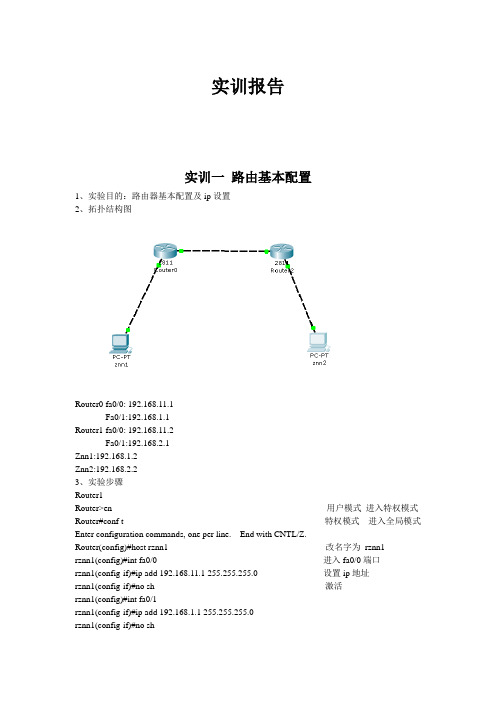
实训报告实训一路由基本配置1、实验目的:路由器基本配置及ip设置2、拓扑结构图Router0 fa0/0: 192.168.11.1Fa0/1:192.168.1.1Router1 fa0/0: 192.168.11.2Fa0/1:192.168.2.1Znn1:192.168.1.2Znn2:192.168.2.23、实验步骤Router1Router>en 用户模式进入特权模式Router#conf t 特权模式进入全局模式Enter configuration commands, one per line. End with CNTL/Z.Router(config)#host rznn1 改名字为rznn1rznn1(config)#int fa0/0 进入fa0/0端口rznn1(config-if)#ip add 192.168.11.1 255.255.255.0 设置ip地址rznn1(config-if)#no sh 激活rznn1(config)#int fa0/1rznn1(config-if)#ip add 192.168.1.1 255.255.255.0rznn1(config-if)#no shrznn1(config-if)#exitrznn1(config)#exitrznn1#copy running-config startup-config 保存Destination filename [startup-config]? startup-configrznn1#conf trznn1(config)#enable secret password 222 设置密文rznn1#show ip interface b 显示Interface IP-Address OK? Method Status Protocol FastEthernet0/0 192.168.11.1 YES manual up up FastEthernet0/1 192.168.1.1 YES manual up upVlan1 unassigned YES manual administratively down downrouter 2outer>enRouter#conf tEnter configuration commands, one per line. End with CNTL/Z.Router(config)#host rznn2rznn2(config)#int fa0/0rznn2(config-if)#ip add 192.168.11.2 255.255.255.0rznn2(config-if)#no shrznn2(config)#int fa0/1rznn2(config-if)#ip add 192.168.2.1 255.255.255.0rznn2(config-if)#no shRznn2#copy running-config startup-config 保存Destination filename [startup-config]? startup-configrznn2(config-if)#exitrznn2(config)#exitrznn2#conf trznn2(config)#enable secret 222rznn2#show ip interface bInterface IP-Address OK? Method Status Protocol FastEthernet0/0 192.168.11.2 YES manual up up FastEthernet0/1 192.168.2.1 YES manual up upVlan1 unassigned YES manual administratively down down实训二1、远程登录、密码设置及验证为路由器开设telnet端口,PC机可以远程登陆到Rznn3(Router 1)拓扑结构图Router0:192.168.1.1Pc:192.168.1.2步骤rznn3>rznn3>enrznn3#conf tEnter configuration commands, one per line. End with CNTL/Z.rznn3(config)#no ip domain lookuprznn3(config)#line cons 0rznn3(config-line)#password znnrznn3(config-line)#loginrznn3(config-line)#no exec-trznn3(config-line)#logg syncrznn3(config-line)#exitrznn3(config)#int fa0/0rznn3(config-if)#ip add 192.168.1.1 255.255.255.0rznn3(config-if)#no shrznn3(config-if)#exitrznn3(config)#line vty 0 4 打通五个端口rznn3(config-line)#password cisco 设置密码rznn3(config-line)#login 保存rznn3(config-line)#exit4、测试:实训三命令组1、目的:八条命令(no ip domain lookup\line cons 0\password\login\no exec-t\logg sync\show version\reload\copy running-config startup-config)\show cdp neighbors)2、拓扑结构图Router0 fa0/0: 192.168.11.1Router1 fa0/0: 192.168.11.23、步骤rznn1#conf tEnter configuration commands, one per line. End with CNTL/Z.1、rznn1(config)#no ip domain lookup 取消域名查找转换2、rznn1(config)#line cons 0 打开cons 0端口3、rznn1(config-line)#password znn 设置密码为znnrznn1(config-line)#login 保存rznn1(config-line)#no exec-t 设置永不超时4、rznn1(config-line)#logg sync 产生日志5、rznn1#show version 显示思科路由系统版本信息Cisco IOS Software, 2800 Software (C2800NM-ADVIPSERVICESK9-M), Version 12.4(15)T1, RELEASE SOFTWARE (fc2)Technical Support: /techsupportCopyright (c) 1986-2007 by Cisco Systems, Inc.Compiled Wed 18-Jul-07 06:21 by pt_rel_team6、rznn1#show cdp neighbors 查看路由器连接的相邻路由器的相关信息Capability Codes: R - Router, T - Trans Bridge, B - Source Route BridgeS - Switch, H - Host, I - IGMP, r - Repeater, P - PhoneDevice ID Local Intrfce Holdtme Capability Platform Port IDrznn2 Fas 0/0 139 R C2800 Fas 0/07、rznn1#copy running-config startup-config 保存刚才指令Destination filename [startup-config]? startup-configBuilding configuration...[OK]8、rznn1#reload 重启路由器Proceed with reload? [confirm]System Bootstrap, Version 12.1(3r)T2, RELEASE SOFTWARE (fc1)Copyright (c) 2000 by cisco Systems, Inc.cisco 2811 (MPC860) processor (revision 0x200) with 60416K/5120K bytes of memorySelf decompressing the image :########################################################################## [OK] Restricted Rights Legendrznn1#show ip interface bInterface IP-Address OK? Method Status Protocol FastEthernet0/0 192.168.11.1 YES manual up up FastEthernet0/1 192.168.1.1 YES manual up upVlan1 unassigned YES manual administratively down down9、rznn1(config-if)#ip add 192.168.3.1 255.255.255.0 重置ip地址rznn1#show ip interface bInterface IP-Address OK? Method Status Protocol FastEthernet0/0 192.168.3.1 YES manual up up FastEthernet0/1 192.168.1.1 YES manual up up Vlan1 unassigned YES manual administratively down down实训四发现协议1、实训目的通过发现协议显示路由器相邻路由的端口信息2、拓扑结构Router0:192.168.11.1Router1:fa0/0 192.168.11.2Fa0/1 192.168.12.1Router2:192.168.12.23、步骤R1路由器Router>enRouter#conf tEnter configuration commands, one per line. End with CNTL/Z.Router(config)#host r1r1(config)#int fa0/0r1(config-if)#ip add 192.168.11.1 255.255.255.0r1(config-if)#no sh%LINK-5-CHANGED: Interface FastEthernet0/0, changed state to upr1(config-if)#r1(config-if)#exitr1(config)#exitr1#%SYS-5-CONFIG_I: Configured from console by consoler1#show ip interface bInterface IP-Address OK? Method Status Protocol FastEthernet0/0 192.168.11.1 YES manual up down FastEthernet0/1 unassigned YES manual administratively down downVlan1 unassigned YES manual administratively down downR2 路由器Router>enRouter#conf tEnter configuration commands, one per line. End with CNTL/Z.Router(config)#host r2r2(config)#int fa0/0r2(config-if)#ip add 192.168.11.2 255.255.255.0r2(config-if)#no sh%LINK-5-CHANGED: Interface FastEthernet0/0, changed state to up%LINEPROTO-5-UPDOWN: Line protocol on Interface FastEthernet0/0, changed state to up r2(config-if)#exitr2(config)#exitr2#%SYS-5-CONFIG_I: Configured from console by consoler2#conf tEnter configuration commands, one per line. End with CNTL/Z.r2(config)#int fa0/0r2(config-if)#int fa0/1r2(config-if)#ip add 192.168.12.1 255.255.255.0r2(config-if)#no sh%LINK-5-CHANGED: Interface FastEthernet0/1, changed state to upr2(config-if)#exitr2(config)#exitr2#%SYS-5-CONFIG_I: Configured from console by consoler2#show ip interface bInterface IP-Address OK? Method Status Protocol FastEthernet0/0 192.168.11.2 YES manual up upFastEthernet0/1 192.168.12.1 YES manual up down Vlan1 unassigned YES manual administratively down downR3路由器Router>enRouter#conf tEnter configuration commands, one per line. End with CNTL/Z.Router(config)#host r3r3(config)#int fa0/0r3(config-if)#ip add 192.168.12.2 255.255.255.0r3(config-if)#no sh%LINK-5-CHANGED: Interface FastEthernet0/0, changed state to up%LINEPROTO-5-UPDOWN: Line protocol on Interface FastEthernet0/0, changed state to up r3(config-if)#exitr3(config)#exitr3#%SYS-5-CONFIG_I: Configured from console by consoler3#show ip interface bInterface IP-Address OK? Method Status Protocol FastEthernet0/0 192.168.12.2 YES manual up up FastEthernet0/1 unassigned YES manual administratively down downVlan1 unassigned YES manual administratively down downR1发现邻居r1#show cdp neighborsCapability Codes: R - Router, T - Trans Bridge, B - Source Route BridgeS - Switch, H - Host, I - IGMP, r - Repeater, P - PhoneDevice ID Local Intrfce Holdtme Capability Platform Port IDr2 Fas 0/0 165 R C2800 Fas 0/0R2发现邻居r2#show cdp neighborsCapability Codes: R - Router, T - Trans Bridge, B - Source Route BridgeS - Switch, H - Host, I - IGMP, r - Repeater, P - PhoneDevice ID Local Intrfce Holdtme Capability Platform Port IDr1 Fas 0/0 176 R C1841 Fas 0/0r3 Fas 0/1 130 R C1841 Fas 0/0R3发现邻居r3#show cdp neighborsCapability Codes: R - Router, T - Trans Bridge, B - Source Route BridgeS - Switch, H - Host, I - IGMP, r - Repeater, P - PhoneDevice ID Local Intrfce Holdtme Capability Platform Port IDr2 Fas 0/0 166 R C2800 Fas 0/14、总结show 命令(1)show ip interface b (显示端口ip信息)(2)show version (显示ios版本信息)(3)show running-config (显示刚才使用的命令配置信息)(4)show cdp neighbors (显示发现邻居直连设备信息)(5)show interface (显示所有端口详细信息)实训五静态路由1、实验目的:将不同网段的网络配通(ip route)Ip route语法:ip route 目标地址子网掩码相邻路由器接口地址Show ip route2、试验拓扑:Router0:192.168.11.1Router1:fa0/0 192.168.11.2Fa0/1 192.168.12.1Router2:192.168.12.23、实验步骤:Router1Router>enRouter#conf tRouter(config)#host r1r1(config)#int fa0/0r1(config-if)#ip add 192.168.11.1 255.255.255.0r1(config-if)#no sh%LINK-5-CHANGED: Interface FastEthernet0/0, changed state to upr1(config-if)#exitr1(config)#exitr1#show ip interface bInterface IP-Address OK? Method Status ProtocolFastEthernet0/0 192.168.11.1 YES manual up downFastEthernet0/1 unassigned YES manual administratively down downVlan1 unassigned YES manual administratively down downr1#%LINEPROTO-5-UPDOWN: Line protocol on Interface FastEthernet0/0, changed state to up r1#ping 192.168.12.1Type escape sequence to abort.Sending 5, 100-byte ICMP Echos to 192.168.12.1, timeout is 2 seconds:.....Success rate is 0 percent (0/5)r1#conf tEnter configuration commands, one per line. End with CNTL/Z.r1(config)#ip route 192.168.12.0 255.255.255.0 192.168.11.2r1(config)#exitr1#ping 192.168.12.1Type escape sequence to abort.Sending 5, 100-byte ICMP Echos to 192.168.12.1, timeout is 2 seconds:Success rate is 100 percent (5/5), round-trip min/avg/max = 31/31/32 msr1#ping 192.168.12.2Type escape sequence to abort.Sending 5, 100-byte ICMP Echos to 192.168.12.2, timeout is 2 seconds:.....Success rate is 0 percent (0/5)r1#ping 192.168.12.2Type escape sequence to abort.Sending 5, 100-byte ICMP Echos to 192.168.12.2, timeout is 2 seconds:Success rate is 100 percent (5/5), round-trip min/avg/max = 47/62/78 msr1#show ip routeCodes: C - connected, S - static, I - IGRP, R - RIP, M - mobile, B - BGPD - EIGRP, EX - EIGRP external, O - OSPF, IA - OSPF inter areaN1 - OSPF NSSA external type 1, N2 - OSPF NSSA external type 2E1 - OSPF external type 1, E2 - OSPF external type 2, E - EGPi - IS-IS, L1 - IS-IS level-1, L2 - IS-IS level-2, ia - IS-IS inter area* - candidate default, U - per-user static route, o - ODRP - periodic downloaded static routeGateway of last resort is not setC 192.168.11.0/24 is directly connected, FastEthernet0/0S 192.168.12.0/24 [1/0] via 192.168.11.2Router3Router>enRouter#conf tEnter configuration commands, one per line. End with CNTL/Z.Router(config)#host r3r3(config)#int fa0/0r3(config-if)#ip add 192.168.12.2 255.255.255.0r3(config-if)#no sh%LINK-5-CHANGED: Interface FastEthernet0/0, changed state to up%LINEPROTO-5-UPDOWN: Line protocol on Interface FastEthernet0/0, changed state to up r3(config-if)#exitr3(config)#exitr3#%SYS-5-CONFIG_I: Configured from console by consoler3#show ip interface bInterface IP-Address OK? Method Status Protocol FastEthernet0/0 192.168.12.2 YES manual up up FastEthernet0/1 unassigned YES manual administratively down downVlan1 unassigned YES manual administratively down downr3#conf tEnter configuration commands, one per line. End with CNTL/Z.r3(config)#ip route 192.168.11.0 255.255.255.0 192.168.12.1r3(config)#exitr3#ping 192.168.11.2Type escape sequence to abort.Sending 5, 100-byte ICMP Echos to 192.168.11.2, timeout is 2 seconds:Success rate is 100 percent (5/5), round-trip min/avg/max = 31/31/32 msr3#ping 192.168.11.1Type escape sequence to abort.Sending 5, 100-byte ICMP Echos to 192.168.11.1, timeout is 2 seconds:Success rate is 100 percent (5/5), round-trip min/avg/max = 62/62/63 msr3#show ip routeCodes: C - connected, S - static, I - IGRP, R - RIP, M - mobile, B - BGPD - EIGRP, EX - EIGRP external, O - OSPF, IA - OSPF inter areaN1 - OSPF NSSA external type 1, N2 - OSPF NSSA external type 2i - IS-IS, L1 - IS-IS level-1, L2 - IS-IS level-2, ia - IS-IS inter area* - candidate default, U - per-user static route, o - ODRP - periodic downloaded static routeGateway of last resort is not setS 192.168.11.0/24 [1/0] via 192.168.12.1C 192.168.12.0/24 is directly connected, FastEthernet0/04、默认路由Route 1r1>enr1#conf tEnter configuration commands, one per line. End with CNTL/Z.r1(config)#no ip route 192.168.12.0 255.255.255.0 192.168.11.2%No matching route to deleter1(config)#exitr1#%SYS-5-CONFIG_I: Configured from console by consoler1#show ip routeCodes: C - connected, S - static, I - IGRP, R - RIP, M - mobile, B - BGPD - EIGRP, EX - EIGRP external, O - OSPF, IA - OSPF inter areaN1 - OSPF NSSA external type 1, N2 - OSPF NSSA external type 2E1 - OSPF external type 1, E2 - OSPF external type 2, E - EGPi - IS-IS, L1 - IS-IS level-1, L2 - IS-IS level-2, ia - IS-IS inter area* - candidate default, U - per-user static route, o - ODRP - periodic downloaded static routeGateway of last resort is not setC 192.168.11.0/24 is directly connected, FastEthernet0/0r1#conf tEnter configuration commands, one per line. End with CNTL/Z.r1(config)#ip route 0.0.0.0 0.0.0.0 192.168.11.2r1(config)#exitr1#%SYS-5-CONFIG_I: Configured from console by consoler1#show ip routeCodes: C - connected, S - static, I - IGRP, R - RIP, M - mobile, B - BGPD - EIGRP, EX - EIGRP external, O - OSPF, IA - OSPF inter areaN1 - OSPF NSSA external type 1, N2 - OSPF NSSA external type 2i - IS-IS, L1 - IS-IS level-1, L2 - IS-IS level-2, ia - IS-IS inter area* - candidate default, U - per-user static route, o - ODRP - periodic downloaded static routeGateway of last resort is 192.168.11.2 to network 0.0.0.0C 192.168.11.0/24 is directly connected, FastEthernet0/0S* 0.0.0.0/0 [1/0] via 192.168.11.2r1#ping 192.168.12.1Type escape sequence to abort.Sending 5, 100-byte ICMP Echos to 192.168.12.1, timeout is 2 seconds:Success rate is 100 percent (5/5), round-trip min/avg/max = 16/28/31 msr1#ping 192.168.12.2Type escape sequence to abort.Sending 5, 100-byte ICMP Echos to 192.168.12.2, timeout is 2 seconds: Success rate is 100 percent (5/5), round-trip min/avg/max = 62/62/63 msRoute 3r1>enr1#conf tEnter configuration commands, one per line. End with CNTL/Z.r1(config)#no ip route 192.168.12.0 255.255.255.0 192.168.11.2%No matching route to deleter1(config)#exitr1#%SYS-5-CONFIG_I: Configured from console by consoler1#show ip routeCodes: C - connected, S - static, I - IGRP, R - RIP, M - mobile, B - BGPD - EIGRP, EX - EIGRP external, O - OSPF, IA - OSPF inter areaN1 - OSPF NSSA external type 1, N2 - OSPF NSSA external type 2E1 - OSPF external type 1, E2 - OSPF external type 2, E - EGPi - IS-IS, L1 - IS-IS level-1, L2 - IS-IS level-2, ia - IS-IS inter area* - candidate default, U - per-user static route, o - ODRP - periodic downloaded static routeGateway of last resort is not setC 192.168.11.0/24 is directly connected, FastEthernet0/0r1#conf tEnter configuration commands, one per line. End with CNTL/Z.r1(config)#ip route 0.0.0.0 0.0.0.0 192.168.11.2r1(config)#exitr1#%SYS-5-CONFIG_I: Configured from console by consoler1#show ip routeCodes: C - connected, S - static, I - IGRP, R - RIP, M - mobile, B - BGPD - EIGRP, EX - EIGRP external, O - OSPF, IA - OSPF inter areaN1 - OSPF NSSA external type 1, N2 - OSPF NSSA external type 2E1 - OSPF external type 1, E2 - OSPF external type 2, E - EGPi - IS-IS, L1 - IS-IS level-1, L2 - IS-IS level-2, ia - IS-IS inter area* - candidate default, U - per-user static route, o - ODRP - periodic downloaded static routeGateway of last resort is 192.168.11.2 to network 0.0.0.0C 192.168.11.0/24 is directly connected, FastEthernet0/0S* 0.0.0.0/0 [1/0] via 192.168.11.2r3#ping 192.168.11.1Type escape sequence to abort.Sending 5, 100-byte ICMP Echos to 192.168.11.1, timeout is 2 seconds: Success rate is 100 percent (5/5), round-trip min/avg/max = 62/62/63 ms实训六动态路由RIP 协议1、实验目的使用配置动态路由启动Rip协议使用到的命令(router rip/network/show ip protocols/show ip route)2、实验拓扑R1 fa0/0 192.168.11.1R2 fa0/0 192.168.11.2fa0/1 192.168.12.1R3 fa0/0 192.168.12.23、实验步骤R1Router>enRouter#conf tEnter configuration commands, one per line. End with CNTL/Z. Router(config)#host r1r1(config)#int fa0/0r1(config-if)#ip add 192.168.11.1 255.255.255.0r1(config-if)#no shr1(config-if)#exitr1(config)#router ripr1(config-router)#network 192.168.11.0r1(config-router)#exitr1(config)#exitr1#%SYS-5-CONFIG_I: Configured from console by consoleR2Router>enRouter#conf tEnter configuration commands, one per line. End with CNTL/Z. Router(config)#host r2r2(config)#int fa0/0r2(config-if)#ip add 192.168.11.2 255.255.255.0r2(config-if)#no shr2(config-if)#exitr2(config)#int fa0/1r2(config-if)#ip add 192.168.12.1 255.255.255.0r2(config-if)#no shr2(config-if)#exitr2(config)#router ripr2(config-router)#network 192.168.11.0r2(config-router)#network 192.168.12.0r2(config-router)#exitr2(config)#exitr2#R3Router>enRouter#conf tEnter configuration commands, one per line. End with CNTL/Z. Router(config)#host r3r3(config)#int fa0/0r3(config-if)#ip add 192.168.12.2 255.255.255.0r3(config-if)#no shr3(config-if)#exitr3(config)#router ripr3(config-router)#network 192.168.12.0r3(config-router)#exitr3(config)#exitr3#%SYS-5-CONFIG_I: Configured from console by console4、实验测试R1r1#show ip protocolsRouting Protocol is "rip"Sending updates every 30 seconds, next due in 10 secondsInvalid after 180 seconds, hold down 180, flushed after 240 Outgoing update filter list for all interfaces is not setIncoming update filter list for all interfaces is not set Redistributing: ripDefault version control: send version 1, receive any version Interface Send Recv Triggered RIP Key-chain FastEthernet0/0 1 2 1Automatic network summarization is in effectMaximum path: 4Routing for Networks:192.168.11.0Passive Interface(s):Routing Information Sources:Gateway Distance Last UpdateDistance: (default is 120)r1#show ip routeCodes: C - connected, S - static, I - IGRP, R - RIP, M - mobile, B - BGPD - EIGRP, EX - EIGRP external, O - OSPF, IA - OSPF inter areaN1 - OSPF NSSA external type 1, N2 - OSPF NSSA external type 2E1 - OSPF external type 1, E2 - OSPF external type 2, E - EGPi - IS-IS, L1 - IS-IS level-1, L2 - IS-IS level-2, ia - IS-IS inter area* - candidate default, U - per-user static route, o - ODRP - periodic downloaded static routeGateway of last resort is not setC 192.168.11.0/24 is directly connected, FastEthernet0/0R 192.168.12.0/24 [120/1] via 192.168.11.2, 00:00:24, FastEthernet0/0 r1#ping 192.168.12.0Type escape sequence to abort.Sending 5, 100-byte ICMP Echos to 192.168.12.0, timeout is 2 seconds: Success rate is 100 percent (5/5), round-trip min/avg/max = 31/31/32 msR2r2#show ip protocolsRouting Protocol is "rip"Sending updates every 30 seconds, next due in 21 secondsInvalid after 180 seconds, hold down 180, flushed after 240Outgoing update filter list for all interfaces is not setIncoming update filter list for all interfaces is not setRedistributing: ripDefault version control: send version 1, receive any versionInterface Send Recv Triggered RIP Key-chain FastEthernet0/0 1 2 1FastEthernet0/1 1 2 1Automatic network summarization is in effectMaximum path: 4Routing for Networks:192.168.11.0192.168.12.0Passive Interface(s):Routing Information Sources:Gateway Distance Last UpdateDistance: (default is 120)r2#show ip routeCodes: C - connected, S - static, I - IGRP, R - RIP, M - mobile, B - BGPD - EIGRP, EX - EIGRP external, O - OSPF, IA - OSPF inter areaN1 - OSPF NSSA external type 1, N2 - OSPF NSSA external type 2E1 - OSPF external type 1, E2 - OSPF external type 2, E - EGPi - IS-IS, L1 - IS-IS level-1, L2 - IS-IS level-2, ia - IS-IS inter area* - candidate default, U - per-user static route, o - ODRP - periodic downloaded static routeGateway of last resort is not setC 192.168.11.0/24 is directly connected, FastEthernet0/0C 192.168.12.0/24 is directly connected, FastEthernet0/1R3r3#show ip protocolsRouting Protocol is "rip"Sending updates every 30 seconds, next due in 15 secondsInvalid after 180 seconds, hold down 180, flushed after 240Outgoing update filter list for all interfaces is not setIncoming update filter list for all interfaces is not setRedistributing: ripDefault version control: send version 1, receive any versionInterface Send Recv Triggered RIP Key-chain FastEthernet0/0 1 2 1Automatic network summarization is in effectMaximum path: 4Routing for Networks:192.168.12.0Passive Interface(s):Routing Information Sources:Gateway Distance Last UpdateDistance: (default is 120)r3#show ip routeCodes: C - connected, S - static, I - IGRP, R - RIP, M - mobile, B - BGPD - EIGRP, EX - EIGRP external, O - OSPF, IA - OSPF inter areaN1 - OSPF NSSA external type 1, N2 - OSPF NSSA external type 2E1 - OSPF external type 1, E2 - OSPF external type 2, E - EGPi - IS-IS, L1 - IS-IS level-1, L2 - IS-IS level-2, ia - IS-IS inter area* - candidate default, U - per-user static route, o - ODRP - periodic downloaded static routeGateway of last resort is not setR 192.168.11.0/24 [120/1] via 192.168.12.1, 00:00:04, FastEthernet0/0 C 192.168.12.0/24 is directly connected, FastEthernet0/0r3#ping 192.168.11.0Type escape sequence to abort.Sending 5, 100-byte ICMP Echos to 192.168.11.0, timeout is 2 seconds: Success rate is 100 percent (5/5), round-trip min/avg/max = 31/31/32 ms实训七负载平衡试训目的实现负载平衡实训拓扑R1 fa0/0 192.168.11.1R2 eth0/0/0 192.168.11.2Fa0/0 192.168.12.1Fa0/0 192.168.13.1R3 fa0/0 192.168.12.2Fa0/1 192.168.14.1R4 fa0/0 192.168.13.2Fa0/1 192.168.15.1R5 fa0/0 192.168.14.2Fa0/1 192.168.15.2实训步骤(R1 )r1>enR1#conf tR1(config)#ip route 0.0.0.0 0.0.0.0 192.168.11.2R1(config)#exitr1#show ip routeCodes: C - connected, S - static, I - IGRP, R - RIP, M - mobile, B - BGPD - EIGRP, EX - EIGRP external, O - OSPF, IA - OSPF inter areaN1 - OSPF NSSA external type 1, N2 - OSPF NSSA external type 2E1 - OSPF external type 1, E2 - OSPF external type 2, E - EGPi - IS-IS, L1 - IS-IS level-1, L2 - IS-IS level-2, ia - IS-IS inter area* - candidate default, U - per-user static route, o - ODRP - periodic downloaded static routeGateway of last resort is 192.168.11.2 to network 0.0.0.0C 192.168.11.0/24 is directly connected, FastEthernet0/0S* 0.0.0.0/0 [1/0] via 192.168.11.2(R2)r2>enr2(config)#ip route 0.0.0.0 0.0.0.0 192.168.12.2r2(config)#ip route 0.0.0.0 0.0.0.0 192.168.13.2r2(config)#exitr2#%SYS-5-CONFIG_I: Configured from console by consoles% Ambiguous command: "s"r2#show ip routeCodes: C - connected, S - static, I - IGRP, R - RIP, M - mobile, B - BGPD - EIGRP, EX - EIGRP external, O - OSPF, IA - OSPF inter areaN1 - OSPF NSSA external type 1, N2 - OSPF NSSA external type 2E1 - OSPF external type 1, E2 - OSPF external type 2, E - EGPi - IS-IS, L1 - IS-IS level-1, L2 - IS-IS level-2, ia - IS-IS inter area* - candidate default, U - per-user static route, o - ODRP - periodic downloaded static routeGateway of last resort is 192.168.12.2 to network 0.0.0.0C 192.168.11.0/24 is directly connected, Ethernet0/0/0C 192.168.12.0/24 is directly connected, FastEthernet0/0C 192.168.13.0/24 is directly connected, FastEthernet0/1S* 0.0.0.0/0 [1/0] via 192.168.12.2[1/0] via 192.168.13.2(R3)r3>enr3#conf tEnter configuration commands, one per line. End with CNTL/Z.r3(config)#ip route 0.0.0.0 0.0.0.0 192.168.12.1r3(config)#exitr3#%SYS-5-CONFIG_I: Configured from console by consoler3#show ip routeCodes: C - connected, S - static, I - IGRP, R - RIP, M - mobile, B - BGPD - EIGRP, EX - EIGRP external, O - OSPF, IA - OSPF inter areaN1 - OSPF NSSA external type 1, N2 - OSPF NSSA external type 2E1 - OSPF external type 1, E2 - OSPF external type 2, E - EGPi - IS-IS, L1 - IS-IS level-1, L2 - IS-IS level-2, ia - IS-IS inter area* - candidate default, U - per-user static route, o - ODRP - periodic downloaded static routeGateway of last resort is 192.168.12.1 to network 0.0.0.0C 192.168.12.0/24 is directly connected, FastEthernet0/0C 192.168.14.0/24 is directly connected, FastEthernet0/1S* 0.0.0.0/0 [1/0] via 192.168.12.1(R4)r4>enr4#conf tEnter configuration commands, one per line. End with CNTL/Z.r4(config)#ip route 0.0.0.0 0.0.0.0 192.168.13.1r4(config)#exitr4#%SYS-5-CONFIG_I: Configured from console by consoler4#show ip routeCodes: C - connected, S - static, I - IGRP, R - RIP, M - mobile, B - BGPD - EIGRP, EX - EIGRP external, O - OSPF, IA - OSPF inter areaN1 - OSPF NSSA external type 1, N2 - OSPF NSSA external type 2E1 - OSPF external type 1, E2 - OSPF external type 2, E - EGPi - IS-IS, L1 - IS-IS level-1, L2 - IS-IS level-2, ia - IS-IS inter area* - candidate default, U - per-user static route, o - ODRP - periodic downloaded static routeGateway of last resort is 192.168.13.1 to network 0.0.0.0C 192.168.13.0/24 is directly connected, FastEthernet0/0C 192.168.15.0/24 is directly connected, FastEthernet0/1S* 0.0.0.0/0 [1/0] via 192.168.13.1(R5)r5>enr5#conf tEnter configuration commands, one per line. End with CNTL/Z.r5(config)#ip route 0.0.0.0 0.0.0.0 192.168.14.1r5(config)#ip route 0.0.0.0 0.0.0.0 192.168.15.1r5(config)#exitr5#%SYS-5-CONFIG_I: Configured from console by consoler5#show ip routeCodes: C - connected, S - static, I - IGRP, R - RIP, M - mobile, B - BGPD - EIGRP, EX - EIGRP external, O - OSPF, IA - OSPF inter areaN1 - OSPF NSSA external type 1, N2 - OSPF NSSA external type 2E1 - OSPF external type 1, E2 - OSPF external type 2, E - EGPi - IS-IS, L1 - IS-IS level-1, L2 - IS-IS level-2, ia - IS-IS inter area* - candidate default, U - per-user static route, o - ODRP - periodic downloaded static routeGateway of last resort is 192.168.14.1 to network 0.0.0.0C 192.168.14.0/24 is directly connected, FastEthernet0/0C 192.168.15.0/24 is directly connected, FastEthernet0/1S* 0.0.0.0/0 [1/0] via 192.168.14.1[1/0] via 192.168.15.1实训测试(R1)r1#ping 192.168.14.1Type escape sequence to abort.Sending 5, 100-byte ICMP Echos to 192.168.14.1, timeout is 2 seconds:Success rate is 100 percent (5/5), round-trip min/avg/max = 62/84/94 ms (R5)r5#ping 192.168.11.1Type escape sequence to abort.Sending 5, 100-byte ICMP Echos to 192.168.11.1, timeout is 2 seconds: Success rate is 100 percent (5/5), round-trip min/avg/max = 79/91/94 ms实训八DHCP 协议配置实训目的全网配通实训拓扑Fa0/0 192.168.11.1Fa0/1 192.168.12.1实训步骤Router>enRouter#conf tEnter configuration commands, one per line. End with CNTL/Z.Router(config)#host r1r1(config)#int fa0/0r1(config-if)#ip add 192.168.11.1 255.255.255.0r1(config-if)#no shr1(config-if)#exitr1(config)#int fa0/1r1(config-if)#ip add 192.168.12.1 255.255.255.0r1(config-if)#no shr1(config-if)#exitr1(config)#ip dhcp pool znn //配置一个根地址池znnr1(dhcp-config)#network 192.168.11.0 255.255.255.0 //为所有客户机动态分配的地址段r1(dhcp-config)#default-router 192.168.11.1 //为客户机配置默认的网关r1(dhcp-config)#dns-server 192.168.11.1 //为客户机配置DNS服务器r1(dhcp-config)#exitr1(config)#ip dhcp pool znn1r1(dhcp-config)#network 192.168.12.0 255.255.255.0r1(dhcp-config)#default-router 192.168.12.1r1(dhcp-config)#dns-server 192.168.12.1r1(dhcp-config)#exit。
路由器与交换机配置实训总结(完整版)应付老师必备

天津电子信息职业技术学院通信网络与数据通信课程实训课题名称通信网络与数据通信姓名学号班级专业所在系指导教师完成日期年月日一、实训目的、要求(概述)二、仿真(命令解释,截图等)三、中兴设备配置(可以拍照,截图)四、总结(收获,不足,体会等)(1)实训目的:1.初步认识packet Tracer软件的工作环境;2.初步认识网络拓扑中的常用设备(路由器、交换机等);3.认识交叉线和直连线(2)、实训要求:1.按照题目要求进行网络拓扑图设计;2.对题目中的拓扑图正确连线,并使所有连线up;3.能够对交换机或路由器添加或删除模块;4.对各主机能够进行IP设置。
图示:如图完成任务要求一对Switch0进行配置:Switch>enSwitch#conf tEnter configuration commands, one per line. End with CNTL/Z. Switch(config)#vlan 10Switch(config-vlan)#exiSwitch(config)#interface fa 0/2Switch(config-if)#switchport access vlan 10Switch(config-if)#exiSwitch(config)#interface fa 0/1Switch(config-if)#switchport mode trunkSwitch(config-if)#exiSwitch(config)#interface fa 0/3Switch(config-if)#switchport mode trunk%LINEPROTO-5-UPDOWN: Line protocol on Interface FastEthernet0/3, changed state to down%LINEPROTO-5-UPDOWN: Line protocol on Interface FastEthernet0/3, changed state to upSwitch(config-if)#exiSwitch(config)#end%SYS-5-CONFIG_I: Configured from console by consoleSwitch#wrBuilding configuration...[OK]二对Switch1进行配置:Switch>enSwitch#conf tEnter configuration commands, one per line. End with CNTL/Z.Switch(config)#vlan 10Switch(config-vlan)#exiSwitch(config)#vlan 20Switch(config-vlan)#exiSwitch(config)#interface fa 0/2Switch(config-if)#switchport access vlan 10Switch(config-if)#exiSwitch(config)#interface fa 0/3Switch(config-if)#switchport access vlan 20Switch(config-if)#exiSwitch(config)#interface fa 0/1Switch(config-if)#switchport mode trunkSwitch(config-if)#exiSwitch(config)#endSwitch#%SYS-5-CONFIG_I: Configured from console by consoleSwitch#wrBuilding configuration...[OK]三对Router0进行配置:Continue with configuration dialog? [yes/no]: noPress RETURN to get started!Router>enRouter#conf tEnter configuration commands, one per line. End with CNTL/Z.Router(config)#interface fa 0/1Router(config-if)#ip add 192.168.12.1 255.255.255.0Router(config-if)#no shutdown%LINK-5-CHANGED: Interface FastEthernet0/1, changed state to up%LINEPROTO-5-UPDOWN: Line protocol on Interface FastEthernet0/1, changed state to upRouter(config-if)#exiRouter(config)#interface fa 0/0Router(config-if)#no shutdown%LINK-5-CHANGED: Interface FastEthernet0/0, changed state to up%LINEPROTO-5-UPDOWN: Line protocol on Interface FastEthernet0/0, changed state to upRouter(config-if)#exiRouter(config)#interface fa 0/0.1%LINK-5-CHANGED: Interface FastEthernet0/0.1, changed state to up%LINEPROTO-5-UPDOWN: Line protocol on Interface FastEthernet0/0.1, changed state to upRouter(config-subif)#encapsulation dot1Q 10Router(config-subif)#ip add 192.168.1.1 255.255.255.0Router(config-subif)#no shutdownRouter(config-subif)#exiRouter(config)#interface fa 0/0.2%LINK-5-CHANGED: Interface FastEthernet0/0.2, changed state to up%LINEPROTO-5-UPDOWN: Line protocol on Interface FastEthernet0/0.2, changed state to upRouter(config-subif)#encapsulation dot1Q 20Router(config-subif)#ip add 192.168.2.1 255.255.255.0Router(config-subif)#no shutdownRouter(config-subif)#exiRouter(config)#router ripRouter(config-router)#network 192.168.12.0Router(config-router)#network 192.168.1.0Router(config-router)#network 192.168.2.0Router(config-router)#endRouter#%SYS-5-CONFIG_I: Configured from console by consoleRouter#wrBuilding configuration...[OK]四对Multilayer Switch0进行配置:Switch>enSwitch#conf tEnter configuration commands, one per line. End with CNTL/Z.Switch(config)#vlan 30Switch(config-vlan)#exiSwitch(config)#vlan 40Switch(config-vlan)#exiSwitch(config)#interface fa 0/1Switch(config-if)#switchport access vlan 30Switch(config-if)#exiSwitch(config)#interface fa 0/2Switch(config-if)#switchport access vlan 40Switch(config-if)#exiSwitch(config)#interface vlan 30%LINK-5-CHANGED: Interface Vlan30, changed state to up%LINEPROTO-5-UPDOWN: Line protocol on Interface Vlan30, changed state to up Switch(config-if)#ip add 192.168.12.2 255.255.255.0Switch(config-if)#no shutdownSwitch(config-if)#exiSwitch(config)#interface vlan 40%LINK-5-CHANGED: Interface Vlan40, changed state to up%LINEPROTO-5-UPDOWN: Line protocol on Interface Vlan40, changed state to up Switch(config-if)#ip add 192.168.4.1 255.255.255.0Switch(config-if)#no shutdownSwitch(config-if)#exiSwitch(config)#router ripSwitch(config-router)#network 192.168.12.0Switch(config-router)#network 192.168.4.0Switch(config-router)#endSwitch#%SYS-5-CONFIG_I: Configured from console by consoleSwitch#wrBuilding configuration...[OK]Ping 192.168.1.10Ping 192.168.2.10中兴设备配置实训总结:经过这段时间赵老师给我们实训关于思科的路由器与交换机的知识,如交换机配置(vlan trunk vtp),静态路由,动态路由,访问列表, VLAN的创建,不同VLAN和网段的互通等。
思科基础实验(中英文对照)CCNA,CCNP实验

目录实验一路由器基本配置 (1)实验二静态路由 (3)实验三缺省路由 (5)实验四静态路由&缺省路由&CDP协议 (7)实验五三层交换机实现VLAN间通信 (9)实验六Vtp (11)实验七生成树STP (13)实验八RIP路由协议1 (17)实验九RIP路由协议2 (19)实验十OSPF单区域1 (21)实验十一OSPF单区域2 (22)实验十二OSPF单区域3 (24)实验十三EIGRP (26)实验十四ACL标准访问控制列表 (29)实验十五扩展ACL -1 (31)实验十六扩展ACL -2 (33)实验十七专家级访问控制列表 (36)实验十八动态NAT (37)实验十九NAT地址转换 (39)实验二十单臂路由 (41)实验二十一PPP chap认证 (43)实验二十二研究应用层和传输层协议 (44)实验二十三检查路由 (45)实验二十四研究ICMP 数据包 (47)实验二十五研究第2 层帧头 (49)实验二十六地址解析协议(ARP) (50)实验二十七中间设备用作终端设备 (52)实验二十八管理设备配置 (54)实验一路由器基本配置一、实验设备一台路由器,一台PC,配置线一条。
二、实验要求1.更改路由器名称为RA2.设置password为cisco1,secret为cisco2,vty为cisco3,并要求所有密码都加密。
3.关闭域名查找,命令输入同步。
4.配置以太网口的IP为202.119.249.2195.设置登陆提示信息6.对串行口进行描述(描述信息为:welcome to lixin lab)7.将上述信息保存到tftp server8.将实验过程配置写在记事本中进行粘贴。
9.配置VTY访问权限。
10.禁止路由器进行域名解析。
三、实验步骤Router>enableRouter#configure terminalRouter(config)#hostname RA 设置路由器名RA(config)#enable password cisco1 设置密码RA(config)#enable secret cisco2 设置加密密码RA (config)#no ip domain-lookup关闭域名查找(当我们打错命令时,不会去查找DNS,造成延时)RA (config)#line console 0RA (config-line)#logging synchronous命令输入达到同步(信息提示不会打断你的输入)RA (config-line)#exec-timeout 0 0 设置永久不超时RA (config-line)#exitRA(config)#line vty 0 4RA(config-line)#(enable)password cisco3 设置vty密码RA(config-line)#exitRA(config)#service password-encryption 对密码加密RA(config)#int fastEthernet 0/0RA(config-if)#ip address 202.119.249.1 255.255.255.0 对以太网口fa0/0配置IP RA(config-if)#no shutdown 开启端口RA(config-if)#exitRA(config)#banner motd & welcome welcome to ccna lab & 设置登陆提示信息RA(config)#int fa0/1RA(config-if)#description this is a fast port 描述端口信息RA(config-if)#exitRA(config)#copy running-config tftp 把信息保存到tftp实验二静态路由一、实验设备两台28系列型号路由器通过串口相连。
CCNA实验-VLAN,TRUNK,VTP和VLAN间路由的使用和配置-带步骤
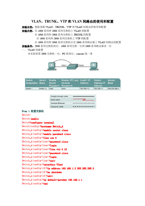
VLAN、TRUNK、VTP和VLAN间路由的使用和配置实验目的:熟练掌握VLAN,TRUNK,VTP和VLAN间路由的使用和配置实验内容:在1900系列和2900系列交换机上VLAN的配置在1900系列和2900系列交换机上TRUNK的配置在1900系列和2900系列交换机上VTP的配置在1900系列和2900系列交换机以及2600系列路由器上VLAN间路由的配置实验条件:2900系列交换机两台,1900系列交换一台和2600系列路由器各一台一.VLAN的配置本实验需要2900交换机一台,PC机两台,console线一条Step 1 配置交换机Switch>Switch>enableSwitch#configure terminalSwitch(config)#hostname Switch_ASwitch_A(config)#enable secret classSwitch_A(config)#enable password ciscoSwitch_A(config)#line con 0Switch_A(config-line)#password ciscoSwitch_A(config-line)#loginSwitch_A(config-line)#line vty 0 15Switch_A(config-line)#password ciscoSwitch_A(config-line)#loginSwitch_A(config-line)#exitSwitch_A(config)#interface Vlan1Switch_A(config-if)#ip address 192.168.1.2 255.255.255.0Switch_A(config-if)#no shutdownSwitch_A(config-if)#exitSwitch_A(config)#ip default-gateway 192.168.1.1Switch_A(config)#endStep 2 为PC配置正确的IP地址,子网掩码和缺省网关Step 3 检测连通性由switch ping两台PC机,检测连通性Step 4 显示VLAN的接口信息2900:Switch_A#show vlan1900:Switch_A#show vlan-membershipStep 5 创建,命名VLAN2900:Switch_A#vlan databaseSwitch_A(vlan)#vlan 2 name VLAN2Switch_A(vlan)#vlan 3 name VLAN3Switch_A(vlan)#exit1900:Switch_A#configure terminalSwitch_A(config)#vlan 2 name VLAN2Switch_A(config)#vlan 3 name VLAN3Step 6 安排4,5,6端口到VLAN 22900:Switch_A#configure terminalSwitch_A(config)#interface fastethernet 0/4 Switch_A(config-if)#switchport mode access Switch_A(config-if)#switchport access vlan 2 Switch_A(config-if)#interface fastethernet 0/5 Switch_A(config-if)#switchport mode access Switch_A(config-if)#switchport access vlan 2 Switch_A(config-if)#interface fastethernet 0/6 Switch_A(config-if)#switchport mode access Switch_A(config-if)#switchport access vlan 2 Switch_A(config-if)#end1900:Switch_A#configure terminalSwitch_A(config)#interface Ethernet 0/4Switch_A(config-if)#vlan static 2Switch_A(config-if)#interface Ethernet 0/5 Switch_A(config-if)#vlan static 2Switch_A(config-if)#interface Ethernet 0/6 Switch_A(config-if)#vlan static 2Switch_A(config)#endStep 7 显示VLAN的接口信息2900:Switch_A#show vlan1900:Switch_A#show vlan-membershipStep 8 安排7,8,9端口到VLAN 3Switch_A#configure terminalSwitch_A(config-if)#interface fastethernet 0/7 Switch_A(config-if)#switchport mode access Switch_A(config-if)#switchport access vlan 3 Switch_A(config-if)#interface fastethernet 0/8 Switch_A(config-if)#switchport mode access Switch_A(config-if)#switchport access vlan 3 Switch_A(config-if)#interface fastethernet 0/9 Switch_A(config-if)#switchport mode access Switch_A(config-if)#switchport access vlan 3 Switch_A(config-if)#endStep 9 显示VLAN的接口信息2900:Switch_A#show vlan1900:Switch_A#show vlan-membershipStep 10 测试VLANsStep 11 解除VLAN与端口的绑定2900:Switch_A#configure terminalSwitch_A(config)#interface fastethernet 0/4 Switch_A(config-if)#no switchport access vlan 2 1900:Switch_A#configure terminalSwitch_A(config)#interface Ethernet 0/4Switch_A(config-if)#no vlan-membership 2Switch_A(config-if)#endStep 12 显示VLAN的接口信息2900:Switch_A#show vlan1900:Switch_A#show vlan-membershipStep 13 删除VLAN2900:Switch_A#vlan databaseSwitch_A(vlan)#no vlan 3Deleting VLAN 3Switch_A(vlan)#exit1900:Switch_A#configure terminalSwitch_A(config)#interface ethernet 0/7Switch_A(config-if)#no vlan 3Switch_A(config-if)#exitStep 14 显示VLAN的接口信息2900:Switch_A#show vlan1900:Switch_A#show vlan-membership二.VLAN的TRUNK配置本实验需要2900交换机两台,PC机两台,console线一条(一)ISLStep 1 配置交换机的基本参数参考上面的实验Step 2 为PC配置正确的IP地址,子网掩码和缺省网关Step 3 检测连通性由switch ping两台PC机,检测连通性Step 4 显示VLAN的接口信息Switch_A#show vlanStep 5 在Switch_A上创建,命名VLANSwitch_A#vlan databaseSwitch_A(vlan)#vlan 10 name AccountingSwitch_A(vlan)#vlan 20 name MarketingSwitch_A(vlan)#vlan 30 name EngineeringSwitch_A(vlan)#exitStep 6 安排4,5,6端口到VLAN 10Switch_A(config)#interface fastethernet 0/4Switch_A(config-if)#switchport mode accessSwitch_A(config-if)#switchport access vlan 10Switch_A(config-if)#interface fastethernet 0/5Switch_A(config-if)#switchport mode accessSwitch_A(config-if)#switchport access vlan 10Switch_A(config-if)#interface fastethernet 0/6Switch_A(config-if)#switchport mode accessSwitch_A(config-if)#switchport access vlan 10Switch_A(config-if)#endStep 7 安排端口7,8,9到VLAN 20Switch_A#configure terminalSwitch_A(config)#interface fastethernet 0/7Switch_A(config-if)#switchport mode accessSwitch_A(config-if)#switchport access vlan 20Switch_A(config-if)#interface fastethernet 0/8Switch_A(config-if)#switchport mode accessSwitch_A(config-if)#switchport access vlan 20Switch_A(config-if)#interface fastethernet 0/9Switch_A(config-if)#switchport mode accessSwitch_A(config-if)#switchport access vlan 20Switch_A(config-if)#endStep 8 安排端口10,11,12到VLAN 30Switch_A#configure terminalSwitch_A(config)#interface fastethernet 0/10Switch_A(config-if)#switchport mode accessSwitch_A(config-if)#switchport access vlan 30Switch_A(config-if)#interface fastethernet 0/11Switch_A(config-if)#switchport mode accessSwitch_A(config-if)#switchport access vlan 30Switch_A(config-if)#interface fastethernet 0/12Switch_A(config-if)#switchport mode accessSwitch_A(config-if)#switchport access vlan 30Switch_A(config-if)#endStep 9 在Switch_B上创建,命名VLAN重复5-8步,在Switch_B创建,命名VLANStep 10 显示VLAN的接口信息Switch_A#show vlanStep 11 测试VLANsStep 12 创建ISL trunkSwitch_A(config)#interface fastethernet 0/1Switch_A(config-if)#switchport mode trunkSwitch_A(config-if)#switchport trunk encapsulation islSwitch_A(config-if)#endSwitch_B(config)#interface fastethernet 0/1Switch_B(config-if)#switchport mode trunkSwitch_B(config-if)#switchport trunk encapsulation isl Switch_B(config-if)#endStep 13 测试ISL trunk(二)dot1qStep 1 配置交换机的基本参数参考上面的实验Step 2 为PC配置正确的IP地址,子网掩码和缺省网关Step 3 检测连通性由switch ping两台PC机,检测连通性Step 4 显示VLAN的接口信息Switch_A#show vlanStep 5 在Switch_A上创建,命名VLANSwitch_A#vlan databaseSwitch_A(vlan)#vlan 10 name AccountingSwitch_A(vlan)#vlan 20 name MarketingSwitch_A(vlan)#vlan 30 name EngineeringSwitch_A(vlan)#exitStep 6 安排4,5,6端口到VLAN 10Switch_A(config-if)#switchport mode accessSwitch_A(config-if)#switchport access vlan 10Switch_A(config-if)#interface fastethernet 0/5Switch_A(config-if)#switchport mode accessSwitch_A(config-if)#switchport access vlan 10Switch_A(config-if)#interface fastethernet 0/6Switch_A(config-if)#switchport mode accessSwitch_A(config-if)#switchport access vlan 10Switch_A(config-if)#endStep 7 安排端口7,8,9到VLAN 20Switch_A#configure terminalSwitch_A(config)#interface fastethernet 0/7Switch_A(config-if)#switchport mode accessSwitch_A(config-if)#switchport access vlan 20Switch_A(config-if)#interface fastethernet 0/8Switch_A(config-if)#switchport mode accessSwitch_A(config-if)#switchport access vlan 20Switch_A(config-if)#interface fastethernet 0/9Switch_A(config-if)#switchport mode accessSwitch_A(config-if)#switchport access vlan 20Switch_A(config-if)#endStep 8 安排端口10,11,12到VLAN 30Switch_A#configure terminalSwitch_A(config)#interface fastethernet 0/10Switch_A(config-if)#switchport mode accessSwitch_A(config-if)#switchport access vlan 30Switch_A(config-if)#interface fastethernet 0/11Switch_A(config-if)#switchport mode accessSwitch_A(config-if)#switchport access vlan 30Switch_A(config-if)#interface fastethernet 0/12Switch_A(config-if)#switchport mode accessSwitch_A(config-if)#switchport access vlan 30Switch_A(config-if)#endStep 9 在Switch_B上创建,命名VLAN重复5-8步,在Switch_B创建,命名VLANStep 10 显示VLAN的接口信息Switch_A#show vlanStep 11 测试VLANsStep 12 创建dot1q trunkSwitch_A(config)#interface fastethernet 0/1Switch_A(config-if)#switchport mode trunkSwitch_A(config-if)#switchport trunk encapsulation dot1q Switch_A(config-if)#endSwitch_B(config-if)#switchport mode trunkSwitch_B(config-if)#switchport trunk encapsulation dot1q Switch_B(config-if)#endStep 13 测试dot1q trunk三.VLAN的VTP配置本实验需要2900交换机两台,PC机两台,console线一条Step 1 配置交换机参考上面的实验Step 2 为PC配置正确的IP地址,子网掩码和缺省网关Step 3 测试连接性由switch ping两台PC机,检测连通性Step 4 显示VLAN接口信息Switch_A#show vlanStep 5 配置VTP服务器端Switch_A#vlan databaseSwitch_A(vlan)#vtp serverSwitch_A(vlan)#vtp domain group1Switch_A(vlan)#exitStep 6 创建,命名VLANsSwitch_A#vlan databaseSwitch_A(vlan)#vlan 10 name AccountingSwitch_A(vlan)#vlan 20 name MarketingSwitch_A(vlan)#vlan 30 name EngineeringSwitch_A(vlan)#exitStep 7 安排端口4,5,6到VLAN 10Switch_A#configure terminalSwitch_A(config)#interface fastethernet 0/4Switch_A(config-if)#switchport mode accessSwitch_A(config-if)#switchport access vlan 10Switch_A(config-if)#interface fastethernet 0/5Switch_A(config-if)#switchport mode accessSwitch_A(config-if)#switchport access vlan 10Switch_A(config-if)#interface fastethernet 0/6Switch_A(config-if)#switchport mode accessSwitch_A(config-if)#switchport access vlan 10Switch_A(config-if)#endStep 8 安排端口7,8,9到VLAN 20Switch_A#configure terminalSwitch_A(config)#interface fastethernet 0/7Switch_A(config-if)#switchport mode accessSwitch_A(config-if)#switchport access vlan 20Switch_A(config-if)#interface fastethernet 0/8Switch_A(config-if)#switchport mode accessSwitch_A(config-if)#switchport access vlan 20Switch_A(config-if)#interface fastethernet 0/9Switch_A(config-if)#switchport mode accessSwitch_A(config-if)#switchport access vlan 20Switch_A(config-if)#endStep 9 安排端口10,11,12到VLAN 30Switch_A#configure terminalSwitch_A(config)#interface fastethernet 0/10Switch_A(config-if)#switchport mode accessSwitch_A(config-if)#switchport access vlan 30Switch_A(config-if)#interface fastethernet 0/11Switch_A(config-if)#switchport mode accessSwitch_A(config-if)#switchport access vlan 30Switch_A(config-if)#interface fastethernet 0/12Switch_A(config-if)#switchport mode accessSwitch_A(config-if)#switchport access vlan 30Switch_A(config-if)#endStep 10 显示VLAN接口信息Switch_A#show vlanStep 11 配置VTP客户端Enter the following commands to configure Switch_B to be a VTP client: Switch_B#vlan databaseSwitch_B(vlan)#vtp clientSwitch_B(vlan)#vtp domain group1Switch_B(vlan)#exitStep 12 创建trunkSwitch_A(config)#interface fastethernet 0/1Switch_A(config-if)#switchport mode trunkSwitch_A(config-if)#endSwitch_B(config)#interface fastethernet 0/1Switch_B(config-if)#switchport mode trunkSwitch_B(config-if)#end2900:Note that it is necessary to specify the encapsulation on a 2924XL, since it supports 802.1Qand ISL.Switch_A(config)#interface fastethernet0/1Switch_A(config-if)#switchport mode trunkSwitch_A(config-if)#switchport trunk encapsulation dot1qSwitch_A(config-if)#endSwitch_B(config)#interface fastethernet0/1Switch_B(config-if)#switchport mode trunkSwitch_B(config-if)#switchport trunk encapsulation dot1qSwitch_B(config-if)#endStep 13 测试trunkshow interface fastethernet 0/1 switchportStep 14 显示VLAN接口信息Switch_B#show vlanStep 15 安排端口4,5,6到VLAN 10Switch_B#configure terminalSwitch_B(config)#interface fastethernet 0/4Switch_B(config-if)#switchport mode accessSwitch_B(config-if)#switchport access vlan 10Switch_B(config-if)#interface fastethernet 0/5Switch_B(config-if)#switchport mode accessSwitch_B(config-if)#switchport access vlan 10Switch_B(config-if)#interface fastethernet 0/6Switch_B(config-if)#switchport mode accessSwitch_B(config-if)#switchport access vlan 10Switch_B(config-if)#endStep 16 Assign ports to VLAN 20Switch_B#configure terminalSwitch_B(config)#interface fastethernet 0/7Switch_B(config-if)#switchport mode accessSwitch_B(config-if)#switchport access vlan 20Switch_B(config-if)#interface fastethernet 0/8Switch_B(config-if)#switchport mode accessSwitch_B(config-if)#switchport access vlan 20Switch_B(config-if)#interface fastethernet 0/9 Switch_B(config-if)#switchport mode access Switch_B(config-if)#switchport access vlan 20 Switch_B(config-if)#endStep 17 Assign ports to VLAN 30Switch_B#configure terminalSwitch_B(config)#interface fastethernet 0/10 Switch_B(config-if)#switchport mode access Switch_B(config-if)#switchport access vlan 30 Switch_B(config-if)#interface fastethernet 0/11 Switch_B(config-if)#switchport mode access Switch_B(config-if)#switchport access vlan 30 Switch_B(config-if)#interface fastethernet 0/12 Switch_B(config-if)#switchport mode access Switch_B(config-if)#switchport access vlan 30 Switch_B(config-if)#endStep 18 显示VLAN接口信息Switch_A#show vlan四.VLAN间路由的配置本实验需要2621路由器一台,2900交换机一台,PC机两台,console线一条Step 1 配置交换机参考上面的实验Step 2 配置连接到交换机上的主机a. 连接到port 0/5上的PC:IP address 192.168.5.2Subnet mask 255.255.255.0Default gateway 192.168.5.1b. 连接到port 0/9上的PC:IP address 192.168.7.2Subnet mask 255.255.255.0Default gateway 192.168.7.1Step 3 测试连通性Step 4 创建,命名两个VLANs2900:Switch_A#vlan databaseSwitch_A(vlan)#vlan 10 name SalesSwitch_A(vlan)#vlan 20 name SupportSwitch_A(vlan)#exit1900:Switch_A#config terminalSwitch_A(config)#vlan 10 name SalesSwitch_A(config)#vlan 20 name SupportSwitch_A(config)#exitStep 5 安排端口5,6,7,8到VLAN 102900:Switch_A#configure terminalSwitch_A(config)#interface fastethernet 0/5 Switch_A(config-if)#switchport mode access Switch_A(config-if)#switchport access vlan 10 Switch_A(config-if)#interface fastethernet 0/6 Switch_A(config-if)#switchport mode access Switch_A(config-if)#switchport access vlan 10 Switch_A(config-if)#interface fastethernet 0/7 Switch_A(config-if)#switchport mode access Switch_A(config-if)#switchport access vlan 10 Switch_A(config-if)#interface fastethernet 0/8 Switch_A(config-if)#switchport mode access Switch_A(config-if)#switchport access vlan 10 Switch_A(config-if)#end1900:Switch_A#configure terminalSwitch_A(config)#interface ethernet 0/5Switch_A(config-if)vlan static 10Switch_A(config-if)#interface ethernet 0/6 Switch_A(config-if)vlan static 10Switch_A(config-if)#interface ethernet 0/7 Switch_A(config-if)vlan static 10Switch_A(config-if)#interface ethernet 0/8 Switch_A(config-if)vlan static 10Switch_A(config-if)#endStep 6 安排端口910,11,12到VLAN 202900:Switch_A#configure terminalSwitch_A(config)#interface fastethernet 0/9 Switch_A(config-if)#switchport mode access Switch_A(config-if)#switchport access vlan 20 Switch_A(config-if)#interface fastethernet 0/10 Switch_A(config-if)#switchport mode access Switch_A(config-if)#switchport access vlan 20Switch_A(config-if)#interface fastethernet 0/11Switch_A(config-if)#switchport mode acce ssSwitch_A(config-if)#switchport access vlan 20Switch_A(config-if)#interface fastethernet0/12Switch_A(config-if)#switchport mode accessSwitch_A(config-if)#switchport access vlan 20Switch_A(config-if)#end1900:Switch_A#configure terminalSwitch_A(config)#interface ethernet 0/9Switch_A(config-if)vlan static 20Switch_A(config-if)#interface ethernet 0/10Switch_A(config-if)vlan static 20Switch_A(config-if)#interface ethernet 0/11Switch_A(config-if)vlan static 20Switch_A(config-if)#interface ethernet 0/12Switch_A(config-if)vlan static 20Switch_A(config-if)#endStep 7 显示VLAN接口信息Switch_A#show vlanStep 8 创建trunk2900:Switch_A(config)#interface fastethernet0/1Switch_A(config-if)#switchport mode trunkSwitch_A(config-if)#switchport trunk encapsulation dot1qSwitch_A(config-if)#end1900: Note the 1900 switch will only support ISL trunking, not dot1q. Switch_A#configure terminalSwitch_A(config)#interface fastethernet0/26Switch_A(config-if)#trunk onStep 9 配置路由器a. Configure the router with the following data. Note that in order to Router_A(config)#interface fastethernet 0/0Router_A(config-if)#no shutdownRouter_A(config-if)#interface fastethernet 0/0.1Router_A(config-subif)#encapsulation dot1q 1Router_A(config-subif)#ip address 192.168.1.1 255.255.255.0Router_A(config-if)#interface fastethernet 0/0.2Router_A(config-subif)#encapsulation dot1q 10Router_A(config-subif)#ip address 192.168.5.1 255.255.255.0Router_A(config-if)#interface fastethernet 0/0.3Router_A(config-subif)#encapsulation dot1q 20Router_A(config-subif)#ip address 192.168.7.1 255.255.255.0Router_A(config-subif)#endStep 10 保存路由器的配置文件Step 11 显示路由器的路由表Step 12 测试VLANS 和the trunkSwitch>enableSwitch#configure terminalSwitch(config)#hostname Switch_ASwitch_A(config)#enable secret classSwitch_A(config)#line con 0Switch_A(config-line)#password ciscoSwitch_A(config-line)#loginSwitch_A(config-line)#line vty 0 15Switch_A(config-line)#password ciscoSwitch_A(config-line)#loginSwitch_A(config-line)#exitSwitch_A(config)#interface Vlan1Switch_A(config-if)#ip address 192.168.1.2 255.255.255.0 Switch_A(config-if)#no shutdownSwitch_A(config-if)#exitSwitch_A(config)#ip default-gateway 192.168.1.1Switch_A(config)#endSwitch_A#vlan databSwitch_A#vlan databaseSwitch_A(vlan)#vlan 10 name Sal esVLAN 10 added:Name: SalesSwitch_A(vlan)#vlan 20 name SupportVLAN 20 added:Name: SupportSwitch_A(vlan)#exitAPPLY completed.Exiting....Switch_A#configure terminalSwitch_A(config)#interface fastethernet0/5Switch_A(config-if)#switchport mode accessSwitch_A(config-if)#switchport access vlan 10Switch_A(config-if)#interface fastethernet0/6Switch_A(config-if)#switchport mode accessSwitch_A(config-if)#switchport access vlan 10Switch_A(config-if)#interface fastethernet0/7Switch_A(config-if)#switchport mode accessSwitch_A(config-if)#switchport access vlan 10Switch_A(config-if)#interface fastethernet0/8Switch_A(config-if)#switchport mode accessSwitch_A(config-if)#switchport access vlan 10Switch_A(config-if)#endSwitch_A#configure terminalSwitch_A(config)#interface fastethernet0/9Switch_A(config-if)#switchport mode accessSwitch_A(config-if)#switchport access vlan 20Switch_A(config-if)#interface fastethernet0/10Switch_A(config-if)#switchport mode accessSwitch_A(config-if)#switchport access vlan 20Switch_A(config-if)#interface fastethernet0/11Switch_A(config-if)#switchport mode accessSwitch_A(config-if)#switchport access vlan 20Switch_A(config-if)#interface fastethernet0/12Switch_A(config-if)#switchport mode accessSwitch_A(config-if)#switchport access vlan 20Switch_A(config-if)#endSwitch_A#show vlanVLAN Name Status Ports---- --------------------------- --------1 default active Fa0/1, Fa0/2, Fa0/3, Fa0/4,Fa0/13, Fa0/14, Fa0/15, Fa0/16,Fa0/17, Fa0/18, Fa0/19, Fa0/20,Fa0/21, Fa0/22, Fa0/23, Fa0/2410 Sales active Fa0/5, Fa0/6, Fa0/7, Fa0/820 Support active Fa0/9, Fa0/10, Fa0/11, Fa0/121002 fddi-default active1003 token-ring-default active1004 fddinet-default active1005 trnet-default activeVLAN Type SAID MTU Parent RingNo BridgeNo Stp BrdgMode Trans1 Trans2---- ----- ------ ----- ------ ------ -------- ---- -------- ------ ------ 1 enet 100001 1500 - - - - - 0 010 enet 100010 1500 - - - - - 0 020 enet 100020 1500 - - - - - 0 01002 fddi 101002 1500 - - - - - 0 01003 tr 101003 1500 - - - - - 0 01004 fdnet 101004 1500 - - - ieee - 0 01005 trnet 101005 1500 - - - ibm - 0 0Switch_A#configure terminalSwitch_A(config)#interface fastethernet0/1Switch_A(config-if)#switchport mode trunkSwitch_A(config-if)#endRouter>enableRouter#configure terminalRouter(config)#hostname Router_ARouter_A(config)#enable secret classRouter_A(config)#line con 0Router_A(config-line)#password ciscoRouter_A(config-line)#loginRouter_A(config-line)#line vty 0 4Router_A(config-line)#password ciscoRouter_A(config-line)#loginRouter_A(config-line)#exitRouter_A(config)#interface fastethernet 0/0Router_A(config-if)#no shutdownRouter_A(config-if)#interface fastethernet 0/0.1Router_A(config-subif)#encapsulation dot1q 1Router_A(config-subif)#ip address 192.168.1.1 255.255.255.0Router_A(config-subif)#interface fastethernet 0/0.2Router_A(config-subif)#encapsulation dot1q 10Router_A(config-subif)#ip address 192.168.5.1 255.255.255.0Router_A(config-subif)#interface fastethernet 0/0.3Router_A(config-subif)#encapsulation dot1q 20Router_A(config-subif)#ip address 192.168.7.1 255.255.255.0Router_A(config-subif)#endRouter_A#show ip routeCodes: C - connected, S - static, I - IGRP, R - RIP, M - mobile, B - BGP D - EIGRP, EX - EIGRP external, O - OSPF, IA - OSPF inter areaN1 - OSPF NSSA external type 1, N2 - OSPF NSSA external type 2E1 - OSPF external type 1, E2 - OSPF external type 2, E - EGPi - IS-IS, L1 - IS-IS level-1, L2 - IS-IS level-2, ia - IS-IS inter area * - candidate default, U - per-user static route, o - ODRP - periodic downloaded static routeGateway of last resort is not setC 192.168.5.0/24 is directly connected, FastEthernet0/0.2C 192.168.7.0/24 is directly connected, FastEthernet0/0.3C 192.168.1.0/24 is directly connected, FastEthernet0/0.1Router_A#C:\>ping 192.168.5.2Pinging 192.168.5.2 with 32 bytes of data:Reply from 192.168.5.2: bytes=32 time<10ms TTL=127Reply from 192.168.5.2: bytes=32 time<10ms TTL=127Reply from 192.168.5.2: bytes=32 time<10ms TTL=127Reply from 192.168.5.2: bytes=32 time<10ms TTL=127Ping statistics for 192.168.5.2:Packets: Sent = 4, Received = 4, Lost = 0 (0% loss),Approximate round trip times in milli-seconds:Minimum = 0ms, Maximum = 0ms, Average = 0msC:\>ping 192.168.1.2Pinging 192.168.1.2 with 32 bytes of data:Reply from 192.168.1.2: bytes=32 time<10ms TTL=254 Reply from 192.168.1.2: bytes=32 time=40ms TTL=254 Reply from 192.168.1.2: bytes=32 time=20ms TTL=254 Reply from 192.168.1.2: bytes=32 time<10ms TTL=254 Ping statistics for 192.168.1.2:Packets: Sent = 4, Received = 4, Lost = 0 (0% loss), Approximate round trip times in milli-seconds: Minimum = 0ms, Maximum = 40ms, Average = 15ms。
思科Cisco路由器RIP动态路由配置实验案例详解
思科Cisco路由器RIP动态路由配置实验案例详解本⽂讲述了思科Cisco路由器RIP动态路由配置实验。
分享给⼤家供⼤家参考,具体如下:实验九 路由器RIP动态路由配置⼀、实验⽬的1. 掌握RIP协议的配置⽅法:2. 掌握查看通过动态路由协议RIP学习产⽣的路由;3. 熟悉⼴域⽹线缆的链接⽅式;⼆、实验背景 假设校园⽹通过⼀台三层交换机连到校园⽹出⼝路由器上,路由器再和校园外的另⼀台路由器连接。
现要做适当配置,实现校园⽹内部主机与校园⽹外部主机之间的相互通信。
为了简化⽹管的管理维护⼯作,学校决定采⽤RIPV2协议实现互通。
三、技术原理1. RIP(Routing Information Protocols,路由信息协议)是应⽤较早、使⽤较普遍的IGP内部⽹管协议,使⽤于⼩型同类⽹络,是距离⽮量协议;2. RIP协议跳数作为衡量路径开销的,RIP协议⾥规定最⼤跳数为15;3. RIP协议有两个版本:RIPv1和RIPv2,RIPv1属于有类路由协议,不⽀持VLSM,以⼴播形式进⾏路由信息的更新,更新周期为30秒;RIPv2属于⽆类路由协议,⽀持VLSM,以组播形式进⾏路由更细。
四、实验步骤 建⽴建⽴packet tracer拓扑图 (1)在本实验中的三层交换机上划分VLAN10和VLAN20,其中VLAN10⽤于连接校园⽹主机,VLAN20⽤于连接R1。
(2)路由器之间通过V.35电缆通过串⼝连接,DCE端连接在R1上,配置其时钟频率64000。
(3)主机和交换机通过直连线,主机与路由器通过交叉线连接。
(4)在S3560上配置RIPV2路由协议。
(5)在路由器R1、R2上配置RIPV2路由协议。
(6)将PC1、PC2主机默认⽹关设置为与直连⽹路设备接⼝IP地址。
(7)验证PC1、PC2主机之间可以互相同信;五、实验设备 PC 2台;Switch_3560 1台;Router-PT 2台;直连线;交叉线;DCE 串⼝线六、实验拓扑图七、实验命令PC1IP: 192.168.1.2Submask: 255.255.255.0Gateway: 192.168.1.1 PC2IP: 192.168.2.2Submask: 255.255.255.0Gateway: 192.168.2.1S3560enconf thostname S3560vlan 10exitvlan 20exitinterface fa 0/10switchport access vlan 10exitinterface fa 0/20switchport access valn 20exitendshow vlanconf tinterface vlan 10ip address 192.168.1.1 255.255.255.0no shutdownexitinterface vlan 20ip address 192.168.3.1 255.255.255.0no shutdownendshow ip routeshow runingconf trouter ripnetwork 192.168.1.0network 192.168.3.0version 2endshow ip routeR1enconf thostname R1interface fa 0/0no shutdownip address 192.168.3.2 255.255.255.0interface serial 2/0no shutdownip address 192.168.4.1 255.255.255.0clock rate 64000endshow ip routeconf trouter ripnetwork 192.168.3.0network 192.168.4.0version 2exitR2enconf thostname R2interface fa 0/0no shutdownip address 192.168.2.1 255.255.255.0interface serial 2/0no shutdownip address 192.168.4.2 255.255.255.0endshow ip routeconf trouter ripnetwork 192.168.2.0netword 192.168.4.0version 2end⼋、实验结果 配置PC0、PC1的IP地址: 配置S3560: 配置R1: 配置R2: PC0 ping PC1:。
基于Cisco Packet Tracer的路由交换综合实验设计
基于Cisco Packet Tracer的路由交换综合实验设计
一、实验目的
本次实验的目的是通过Cisco Packet Tracer模拟网络环境,进行路由交换的综合实验,以加深对路由器配置和交换机互联的理解,提高实际操作技能。
二、实验环境
1. 软件准备:Cisco Packet Tracer软件
2. 设备准备:2台路由器、3台交换机、若干台电脑
三、实验内容
1. 实验一:路由器基本配置
步骤:
1)在Packet Tracer中拖动两台路由器到画布上,连接它们之间的Seria接口。
2)通过CLI界面对路由器进行基本配置,包括主机名、密码、IP地址、路由协议等。
3)通过ping测试和show命令验证路由器配置是否正确。
四、实验总结
通过以上实验,我们可以掌握路由器和交换机的基本配置方法、互联配置方法以及静态路由和动态路由的配置方法。
在实际工作中,我们需要根据网络规模和需求来选择合适的配置方式,以保障网络的稳定和高效运行。
五、注意事项
1. 在进行实验前,务必熟悉Cisco Packet Tracer的基本操作方法,了解设备的拓扑图和CLI配置界面。
2. 实验中涉及到的命令和配置方法,需要进行充分的练习和理解,避免因配置错误导致网络通信异常。
3. 在进行实验时,可以根据需要进行功能扩展,如配置DHCP服务、访问控制列表等,以提高实验的综合性和实用性。
通过本文的介绍,我们了解了基于Cisco Packet Tracer的路由交换综合实验的设计内容和步骤。
这些实验内容对于提升路由交换技术的实际操作能力和解决网络故障具有重要意义,希望读者能够通过实践不断提升自己的技能水平。
- 1、下载文档前请自行甄别文档内容的完整性,平台不提供额外的编辑、内容补充、找答案等附加服务。
- 2、"仅部分预览"的文档,不可在线预览部分如存在完整性等问题,可反馈申请退款(可完整预览的文档不适用该条件!)。
- 3、如文档侵犯您的权益,请联系客服反馈,我们会尽快为您处理(人工客服工作时间:9:00-18:30)。
精品文档
精品文档实验1 路由器基础命令回顾
一、实验目的
通过本节的练习回顾、熟悉一期课程中涉及到的路由器的相关指令。
掌握路由器的基础配置。
二、实验需要的知识点
一期路由器的基础知识。
三、实验步骤
1、改写主机名。
把路由器的主机名改成:RouterA.。
在全局模式下使用指令的关键字:hostname name
2、配置密码。
进入特权模式的密码为cisco。
配置控制台的密码:cisco
配置远程登录的密码:cisco
在全局模式下使用指令的关键字:enable password password
在全局模式下使用指令的关键字:line vty 0 4
login
password password
在全局模式下使用指令的关键字:line console 0
login
password password
3、配置时钟。
在全局模式下使用指令的关键字:clock set hh::mm::ss mm:dd:yy
4、配置接口ip地址。
在路由器的环回接口配置ip地址:1.1.1.1/24。
在e0
接口上配置ip地址:192.1.1.1/24
在全局模式下使用指令的关键字:interface interface
在接口模式下使用指令的关键字:ip address ip address mask
5、退出,有三种方法。
end
exit
logout
6、保存配置,有两种方法。
copy running-config stratup-config
write
7、停止域名解析查询。
在全局模式下使用指令的关键字:no ip domain lookup
四、检测
在特权模式下使用:show version
2、在特权模式下使用:show interface {interface}。