ARMSTRONG DE 智能变频泵介绍
阿姆斯壮泵工作原理

阿姆斯壮泵工作原理
阿姆斯壮泵是一种智能变频水泵,其工作原理是通过内置PSPC控制技术,控制水泵启停及运行台数,从而在满足系统需求的情况下,使泵组在最佳能效状态下运行,达到系统所需流量。
阿姆斯壮智能变频水泵采用了优秀的自控方法,能够较好地解决生产线负荷波动较大的问题,使水泵运行更加高效。
这种智能变频水泵可以显示瞬时的流量、扬程、功率、电流、频率等参数,并具有手动设定流量、扬程、频率等功能,还具有3个运行模式:泵出口恒压、远端恒压差、恒流量。
阿姆斯壮泵的工作原理为水泵行业的创新和发展提供了新的思路和方向。
泽德商用智能双泵提升泵说明书
泽德商用智能双泵提升泵说明书泽德商用智能双泵提升泵是一种用于提升和排水的机械设备。
本说明书将详细介绍该泵的特点、结构、使用方法和注意事项。
一、特点:1. 智能控制:采用智能控制系统,可以实现自动运行和自动停机,提高了泵的使用便利性和安全性。
2. 双泵结构:该泵采用双泵结构,可以提高提升和排水的效率,同时也增加了泵的使用寿命。
3. 高效性能:配备强力电机和优质叶轮,能够快速将水提升至目标位置,并具有较高的排水能力。
4. 耐用材料:该泵采用优质不锈钢材料制造,具有较高的耐腐蚀性和耐用性。
二、结构:1. 泵体:泵体采用不锈钢材料制造,具有稳定的结构和较高的耐腐蚀性。
2. 叶轮:叶轮采用高质量不锈钢制造,具有良好的涡轮设计,提高了泵的提升和排水能力。
3. 电机:配备高效电机,具有较高的功率和稳定的性能。
三、使用方法:1. 安装:将泵体固定在合适位置,确保泵与水源之间的连接管道正确连接。
2. 连接电源:将泵的电源线与电源插头连接,确保电源稳定。
3. 开启智能控制系统:根据实际需要设置智能控制系统的参数,确保泵的自动运行和停机功能正常。
4. 使用:打开水源阀门,启动泵进行提升和排水操作,根据实际需求控制水的流量和提升高度。
四、注意事项:1. 安装前请务必关闭电源,确保安装过程的安全性。
2. 在使用过程中,应定期检查泵体和连接管道的密封性,确保不存在漏水现象。
3. 在长时间不使用时,应将泵体和管道排空,防止积水导致泵的损坏。
4. 使用过程中如发生异常情况,应立即切断电源并进行检修。
本说明书提供了泽德商用智能双泵提升泵的详细介绍和使用方法,希望能够对用户正确使用该设备提供帮助。
如需更多信息,请参考产品说明书或与生产厂家联系。
神能多级变频水泵说明书
神能多级变频水泵说明书神能多级变频水泵说明书神能多级变频水泵是一种高效、先进的水泵设备,主要用于供水、排水、冷却系统以及工业生产中的液体输送。
本说明书旨在为用户提供生动、全面、具有指导意义的操作指南,以确保用户能够正确、安全地操作和维护神能多级变频水泵。
一、产品概述和特点神能多级变频水泵采用先进的变频技术,能够根据实际使用需求自动调节运行频率,从而提高能效和节能效果。
其特点如下:1. 高效节能:采用变频控制技术,能够根据不同工况实时调节运行频率,最大程度地降低能耗。
2. 稳定可靠:采用优质材料和先进工艺制造,具有耐腐蚀、耐磨损和抗压性能,确保长期稳定运行。
3. 操作简便:智能化控制系统使得操作简单方便,用户只需进行简单设置即可实现自动控制和监测。
4. 安全保护:设有多重保护装置,如过载保护、过温保护和电压保护,确保设备安全运行。
5. 多种应用场景:适用于家庭供水、建筑排水、农田灌溉、工业生产和循环水系统等多个领域。
二、操作指南1. 安装:根据具体需求选择合适的安装位置,确保水泵稳固且离地面垂直。
安装过程中请确保供电线路正确接入,接地良好。
2. 启动:将电源插头插入插座后,按下开关启动水泵。
在启动过程中,请留意是否存在异常声音或振动。
3. 设置运行参数:根据实际需求,设置水泵的运行参数,包括运行频率、运行时间和运行模式等。
请参照附带的使用手册进行正确操作。
4. 监测运行状态:通过水泵自带的显示屏,可以实时监测水泵的运行状态,包括压力、温度和故障信息等。
如发现异常情况,请及时进行处理。
5. 停机:当水泵工作完成或需要停机时,按下停机按钮,等待水泵完全停止后再进行其他操作。
三、维护保养1. 定期清洁:根据水泵使用情况,定期对水泵进行清洁,清除泵体和叶轮上的杂物和沉积物,以保证良好的工作效果。
2. 润滑保养:定期检查水泵的润滑系统,如油位是否正常、油质是否需要更换等,确保水泵正常运转。
3. 检修维护:定期对水泵进行全面检修和维护,包括电气系统、机械传动系统和密封系统等,确保设备的长期稳定运行。
人工智能变频泵控制系统说明书
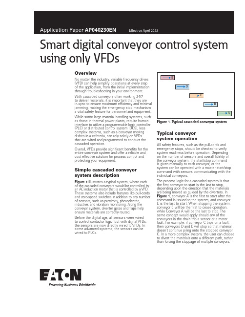
Smart digital conveyor control system using only VFDsOverviewNo matter the industry, variable frequency drives (VFD) can help simplify operations at every stepof the application, from the initial implementation through troubleshooting in your environment. With cascaded conveyors often working 24/7to deliver materials, it is important that they arein-sync to ensure maximum efficiency and minimal jamming, making the emergency stop mechanism a vital safety feature for personnel and equipment. While some large material handling systems, such as those in thermal power plants, require human interface to utilize a programmable logic controller (PLC) or distributed control system (DCS), less complex systems, such as a conveyor moving dishes in a cafeteria, can rely solely on VFDsthat are wired and programmed to conduct the cascaded operation.Overall, VFDs provide significant benefits for the entire conveyor system and offer a reliable and cost-effective solution for process control and protecting your equipment.Simple cascaded conveyor system descriptionFigure 1 illustrates a typical system, where eachof the cascaded conveyors would be controlled by an AC induction motor that is controlled by a VFD. These systems also include features like pull-cords and zero-speed switches in addition to any number of sensors, such as proximity, photoelectric, inductive, and vibration monitoring. Along the conveyor system, diverter gates and flaps help ensure materials are correctly routed.Before the digital age, all sensors were wiredto control contactor logic, but with digital VFDs, the sensors are now directly wired to VFDs. In some advanced systems, the sensors can be wired to PLCs.Figure 1. T ypical cascaded conveyor system Typical conveyorsystem operationAll safety features, such as the pull-cords and emergency stops, should be checked to verify system readiness before operation. Depending on the number of sensors and overall fidelity of the conveyor system, the start/stop commandis given manually to each conveyor, or the system can be operated with a master start/stop command with sensors communicating with the individual conveyors.The process logic for a cascaded system is that the first conveyor to start is the last to stop, depending upon the direction that the materials are being moved as guided by the diverters. In Figure 1, conveyor A is the first to start after the command is issued to the system, and conveyor E is the last to start. When stopping the system, conveyor E will be the first to cease operation, while Conveyor A will be the last to stop. The same concept would apply should any of the conveyors in the chain trip a sensor or a motor fault. For example, if conveyor C trips on a fault, then conveyors D and E will stop so that material doesn’t continue piling onto the stopped conveyor C. In a more complex system, the user can choose to divert the materials onto a different path, rather than forcing the stoppage of multiple conveyors.2Application Paper AP040230ENEffective April 2022Smart digital conveyor control systemusing only VFDsEATON Understanding sensor integrationThe most common sensor used in conveyor systems is a zero-speed switch, which provides feedback as to whether the conveyor is moving or has stopped. While an AC induction motor could be moving because VFDs are putting out voltage, the conveyor could actually be stopped. In that case, the zero-speed switch senses the actual movement—or lack thereof—coming from the conveyor belt. In Figure 1, if the zero-speed switch on conveyor C triggers, then the motors on conveyors C, D, and E will stop to prevent materials from piling up and accidental damage.It is important with the implementation of a zero-speed switch in the controls to begin sensing after the conveyor has started running at a certain frequency, but not before the conveyor has started moving. If the zero-speed switch begins sensing before the conveyor is running, then it will never start.When VFDs were less advanced, PLCs were a must for implementing control of a cascaded conveyor system, and before PLCs, hardware-wired relay controls were used. With advancements in the applications offered by VFD digital controls, most of the control functions required by the simple conveyor system (Figure 1) can be achieved by integrating the sensors to, and in the wiring between, the VFDs. Using only VFDs, rather than integrating PLCs with them, is a more cost-effective solution for achieving the same performance.How to integrate a conveyor system digitally with VFDsFor the following section, refer to Figure 1.Start command: A total of five VFDs—one for each conveyor motor—are connected on the control board. Run feedback from conveyor A is wired to conveyor B, and conveyor B is wired to conveyor C, and so on until all conveyors are connected to one another. The start command is issued to conveyor A, and the run feedback starts conveyor B, while conveyor B starts conveyor C, and onward until conveyor E begins moving. This is how VFD controls start all five conveyors.Conveying speed reference control: The main system speed reference input is only fed to conveyor A ’s VFD. Then, all five of the conveyor’s VFDs feed the speed control signal, i.e., A > B > C > D > E. Changing the speed reference to conveyor A subsequently changes the speed of the conveyors upstream that feed material to conveyor A.Stop/fault command: Just like the start command, the stop/fault command works via the five VFDs connected to one another on the control board. When the stop command is issued, conveyor E will be the first to stop, which is wired to then pass the command to conveyor D, and onward through the cascaded conveyors, i.e., E > D > C > B > A. Each conveyor is wired to the next in the chain, which is how the VFD stops all five conveyors. The faultcommand follows the exact same sequence as the stop command.Sensor interface: Users add more sensors to the conveyor system as fidelity increases. The zero-speed switch for each conveyor is wired to its specific external fault, and if triggered, the VFD will issue a fault to automatically stop the subsequent VFDs in the chain. The zero-speed switch can be bypassed by using drive-relay before the drive is running by setting the drive frequency above that of the moving conveyor. Once the relay picks up the preset speed frequency, it arms the zero-speed input on the same channel as the relay for initial bypass of zero-speed sensing. Simple control is achieved by using VFD digital controls without the need for a PLC.The pull-cords of the conveyors can be wired in series to the STO of the drives. This is the safest way to put an emergency stop on the drives running the motor and is possible to achieve with only VFDs.Figure 2. T ypical relay wiring for zero-speed sensingProximity sensors: Proximity sensors can be connected to the VFDs for a more intelligent start/stop by sensing the materials on the conveyor. Instead of running the systems continuously, it can be started and stopped based on the load that is traveling on the conveyor. This power-saving option enables the VFD to give a start command to the next conveyor in the cascade, only in the event it needs to be activated.Referring again to Figure 1, the proximity sensor would detect a load on conveyor E, and as soon as the load reaches a preset point, it would give a start command to conveyor D and so on until it reaches conveyor A.The same logic applies to the stoppage of conveyors. If the load falls below a certain preset threshold, it triggers a command to the rest of the conveyor system that a load isn’t being transported, thus turning it off to save power.Maintenance management: Sensors with vibration monitoring capabilities can be wired directly to the VFD to trigger a warning and generate a fault command to prevent damage to the system.Use of DM1 for a conveyor applicationSelection of DM1 modelBased on motor current selected for the conveyor, the user can select the DM1 model that supports 150% of the overload. DM1 is available in models capable of 110% or 150% overload for 60 seconds, but the conveyor application requires constant torque. Because of that, the 150% overload model (also known as an IH model) is recommended.In certain applications, the drive is required to deliver 200% overload, and the DM1 can deliver at that level for 2 seconds, every 20 seconds. After delivering the required torque in the overloaded zone, the drive will safely trip if the load demands higher torque for an extended period of time.Power and control wiring of DM1The DM1 installation manual will help determine recommended fuse protection and cable sizes, based on frame size and model. The manual also contains recommendations for grounding, EMC, brake resistor, and control wiring. Users should follow the design guidelines from the manual.Figure 3 shows typical control wiring for the DM1.3Application Paper AP040230ENEffective April 2022Smart digital conveyor control system using only VFDs EATON Figure 3. T ypical control wiring schemePlanning fieldbus control for the conveyorAs illustrated above, the control can be wired to the drive. If the conveyor system has a PLC, the DM1 Pro model offers onboard EtherNet/IP connection or, as an option, a Profibus T card forcontrolling and reading drive data via fieldbus link. The Modbus T RTU is available with every model.Eaton has developed Add-On Instructions (AOIs) for Rockwell PLC that support various assemblies, allowing for simple import to the Rockwell Studio5000, and used in PLC programming for controlling start/stop and speed reference to the DM1 drive. AOI also supports the data read from the PLC. For protocols and application notes to support PLC code implementation, refer to the quick start guide.DM1 software features for controlling conveyors Motor controlMotor control mode: The conveyor application can be run using V/F scalar control or Sensorless Vector Control (SVC). In V/F control mode, DM1 can offer +/–0.5% of base speed across a 30:1 speed range. If the speed reference to the conveyor is changing frequently, SVC control is recommended, which will provide +/–0.5% speed accuracy across a 60:1 speed range for the application.Speed reference: DM1 offers fixed speed reference throughdigital inputs that can be preset for speed reference, or the speed references can be an analog input or Fieldbus control register. DM1 offers various speed acceleration and deceleration profiles built into the drive control algorithms that can be selected by the user to minimize the equipment wear and tear.Start/stop mode: Ramp start/stop applications are typically used for conveyors, but DM1 also offers flying-start if required.Because particular conveyor applications might require a fast start/stop, the minimum programmable deceleration rate offered by DM1 is one-tenth of a second (0.1), but due to load inertia, actual stop time will vary.If the user desires a faster ramp rate than one-tenth of a second (0.1), the user can change the P1.2 setting. The user should make sure the speed reference is tethered to the motor design nominal speed, even though the P1.2 is set higher.For example, P 1.4 = 0.1 sec, P1.1 = 0, and P1.2 = 60 Hz If the drive is running at 40 Hz, then it will take(0.1/60) x 40 = 0.07 sec to drop to 0 Hz and 0.1 sec if the VFD was running at 60 Hz.Then, P 1.4 = 0.1 sec, P1.1 = 0, and P1.2 = 400 Hz The same thing changes if 40 Hz, then it will take(0.1/400) x 40 = 0.01 sec to drop to 0 Hz and 0.015 sec if the VFD was running at 60 Hz.For applications requiring multiple rapid starts/stops, an external dynamic braking resistor (DBR) should be considered, based on application duty cycle and the drive rating recommended in the catalog.Using an overvoltage (OV) regulator in the conveyor application to control the DC bus overvoltage is not recommended, as powermust be rapidly drained from the DC bus to achieve the fastest stop. When using the brake-chopper for external DBR, the user should disable the OV regulator in DM1.DC braking: Along with an external DBR, users can stop the conveyor via DC or flux brakes built into the DM1 drive. Because of the various field variables, it is recommended that brakingperformance is type-tested to determine the required performance.Application notes are available to support DC brake setup.Eaton1000 Eaton Boulevard Cleveland, OH 44122 United States © 2022 EatonAll Rights ReservedPrinted in USAPublication No. AP040230EN / Z26202 April 2022Eaton is a registered trademark.All other trademarks are propertyof their respective owners.Smart digital conveyor control systemusing only VFDsApplication Paper AP040230EN Effective April 2022Application controlIn addition to the standard start/stop control of the DM1, all models have a built-in PI controller for drive speed based on the process-control feedback.The PI controller is available for both inverted and non-inverted actions, and should be selected by the user based on the process. The DM1 Pro model offers more applications than the standard DM1 model.For a model comparison, reference the DM1 application manual. ProtectionsDM1 is a smart digital drive, offering protections to the drive itself, connected motor, and communications interface.Protections include—but are not limited to—motor thermal protection, input phase fault, external interlock fault, undervoltage and overvoltage, and loss of PI feedback.Additionally, the drive supports automatic restarts for certain faults, with the user selecting how many times the drive may restart during a predetermined period.T able 1. Built-in protection featuresDescriptionOvervoltage protection YesOvervoltage trip limit240 V drives: 430 V / 480 V drives: 850 V Undervoltage protection YesUndervoltage trip limit240 V drives: 210 V / 480 V drives: 390 V Earth fault protection YesInput phase supervision YesMotor phase supervision YesOvercurrent protection YesUnit overtemperature protection YesMotor overload protection YesMotor stall protection YesMotor underload protection YesDC bus overvoltage control Yes STO protectionDM1 offers SIL2-certified, built-in Safe Torque Off (STO). STO prevents an unexpected start of the motor, and therefore, stops the drive from producing power/torque to the load. This feature is particularly useful for maintenance and personnel protection.The STO trigger is a stop command to the drive, forcing the motor to coast to a stop. This function is initiated through the hardware circuit rather than the software, disabling the output IGBTs by either disconnecting the power supply to the gate control driver IC (STO1) or disabling the output of the gate control driver IC (STO2).The gate-drive output signals control the IGBT module, andwhen they are disabled, the drive will not generate torque in the motor shaft.More detailed application notes for STO wiring configurationsare available.Figure 4. STO wiring scheme for DM1 using dry contacts。
ARMSTRONGDE智能变频泵介绍课件 (一)
ARMSTRONGDE智能变频泵介绍课件 (一)随着科技的快速发展,人们对于现代生活品质的要求也日益提高,特别是在工业领域,如何提高生产效率、降低成本、提高工作安全与环保性,成为制造企业和工程师关注的热点话题。
于是,ARMSTRONGDE智能变频泵应运而生,它可以实现节能、智能化、可靠、安全、环保等重要功能,成为了工程师们高度赞誉和广泛应用的一款理想设备。
一、首先是ARMSTRONGDE智能变频泵的产品介绍:ARMSTRONGDE智能变频泵是基于差压变频技术和可靠控制算法系统而研制的设备,创新性地将电机与变频驱动技术高度结合,实现了精确控制输送介质的流量、压力、液位等工艺参数,具有智能化、高效节能、精密可靠、使用安全、维护方便等特点。
该设备广泛应用于城市给排水系统、暖通空调系统、工业供水及化工、石油、电力、农业灌溉和消防等领域,具有广阔的市场前景。
二、ARMSTRONGDE智能变频泵的优点:1、高效节能:电机功率根据供水需求自动调节,在水需求升降的不同时段,输出不同的功率,避免过程中的能量浪费,大大提高能源利用效率,降低业主的能源消费。
2、智能化控制:智能程序控制可自动调整水泵的启动、停止,达到无人值守操作的目的,同时设备还具有温度、水位、压力、能耗显示等多项指标,可实现智能的远程监控、远程调试、系统评估。
3、精密稳定:采用先进的可控系统,可根据不同介质的压力、浓度、流量等因素实时维持稳定的工作状态,具有高精度、高稳定性、高效率、低噪音等特点。
4、安全环保:高标准的材料与工艺,确保设备的使用寿命高、磨损小、噪音低,同时该设备在出水和供水中遵循多项国家环保、节能标准,为业主带来更加清洁、健康的用水环境。
三、ARMSTRONGDE智能变频泵的应用优势:1、在城市给排水系统中,可实现水泵的合理运行和水源的平衡调配,确保市政供水和污水管网的稳定和正常排放。
2、在农业灌溉和花园irrigation系统中,可通过智能控制系统,实现流量、压力和水位的自动调节,确保作物的正常生长、根部滋润、产量的保持和节约时间成本。
亚特兰蒂斯公司水下泵产品介绍说明书
1Atlas Copco Dewatering pumps product rangeS u b m e r s i b l e p u m p s S u r f a c e p u m p sT e r m i n o l o g y A c c e s s o r i e s P a r t s a n d S e r v i c e Othe r I nf o r m a t i o n Index Surface pumps• Dry prime pumps (PAS range)• Wet prime pumps (VAR range)• Wellpoint centrifugal pumps (WEL range)Submersible pumps• Drainage pumps (WEDA D range)• Sludge pumps (WEDA S range)• Slurry pumps (WEDA L range)Terminology• Self primingAccessoriesParts and Service• Service packs• Pump parts• Seal kits, Instant Service pack, Wear part kit and Gasket kit,• Fluids and Lubricants• FleetLinkOther information• Friction losses• Utilities table• Hydraulic characteristicsAtlas CopcoDewatering pumps product rangeDry prime pumps (PAS range)Dewatering | Sewage bypass | Ballasting5S u b m e r s i b l e p u m p s S u r f a c e p u m pT e r m i n o l o g yAc c es s o r i e s P a r t s a n d S e r v i c e O t h e r I n f o r m a t i o n Wellpoint pumps (WEL range)Dewatering to build. Construction | Pipeline on shorePolluted soil remediation | TunnelingWet prime pumps (VAR range)Groundlevel process before excavation for footingsDry prime pumpsPAS range68The PAS range of fully automatic self-priming centrifugal pumps are considered the ideal solution for transporting or raising water with abrasive solids in suspension. They are used across multiple industries including construction and mine site dewatering, floodwater, stream diversions, sewage bypass and municipal64128PAS Performance curveAtlas Copco Dewatering pumps product rangePerformance Curves accor. to UNI 9906 Features :Atlas Copco Dewatering pumps product rangeS u b m e r s i b l e p u m p s S u r f a c e p u m p sT e r m i n o l o g y A c c e s s o r i e sP a r t s a n d S e r v i c ee r I nf o r m a t i o nmaintenance.• High capacity diaphragm pump.• Mechanical seal oil bath.• PW 750 controller• Stackable (canopy version)S u b m e r s i b l e p u m p s S u r f a c e p u m p sT e r m i n o l o g y A c c e s s o r i e sP a r t s a n d S e r v i c ee r I nf o r m a t i o nmaintenance.• High capacity diaphragm pump.• Mechanical seal oil bath.• PW 750 controller.• Stackable (canopy version) .S u b m e r s i b l e p u m p s S u r f a c e p u m p sT e r m i n o l o g y A c c e s s o r i e sP a r t s a n d S e r v i c ee r I nf o r m a t i o n• High capacity diaphragm pump.• Easy serviceability.• Mechanical seal oil bath • PW 750 controllerS u b m e r s i b l e p u m p s S u r f a c e p u m p sT e r m i n o l o g y A c c e s s o r i e sP a r t s a n d S e r v i c ee r I nf o r m a t i o n• Hinge kit for pump maintenance.• High capacity diaphragm pump.• Mechanical seal oil bath.• PW 250 controller.• Stackable.S u b m e r s i b l e p u m p s S u r f a c e p u m p sT e r m i n o l o g y A c c e s s o r i e sP a r t s a n d S e r v i c ee r I nf o r m a t i o n• Hinge kit for pump maintenance.• High capacity diaphragm pump.• Mechanical seal oil bath.• PW 250 controller.• Stackable.S u b m e r s i b l e p u m p s S u r f a c e p u m p sT e r m i n o l o g y A c c e s s o r i e sP a r t s a n d S e r v i c ee r I nf o r m a t i o n• Hinge kit for pump maintenance.• High capacity diaphragm pump.• Mechanical seal oil bath.• PW 250 controller.• Stackable.S u b m e r s i b l e p u m p s S u r f a c e p u m p sT e r m i n o l o g y A c c e s s o r i e sP a r t s a n d S e r v i c ee r I nf o r m a t i o n• Hinge kit for pump maintenance.• High capacity diaphragm pump.• Mechanical seal oil bath.• PW 500 controller.• Stackable.S u b m e r s i b l e p u m p s S u r f a c e p u m p sT e r m i n o l o g y A c c e s s o r i e sP a r t s a n d S e r v i c ee r I nf o r m a t i o n• High capacity vacuum pump.• Mechanical seal oil bath.• PW 750 controller.• Stackable.S u b m e r s i b l e p u m p s S u r f a c e p u m p sT e r m i n o l o g y A c c e s s o r i e sP a r t s a n d S e r v i c ee r I nf o r m a t i o nThe VAR range consists on centrifugal pumps, where the key is to have a simplesystem for first prime. The machine can, with a first water fill up, quickly evacuate the air from the suction and allow to flow the fluid with solid handlings in suspension. The equipment suits perfectly in medium construction application,bentonite pumping and portable emergency floods control.Great for construction, general dewatering, drainage and emergency applications.These self-priming centrifugal pumps are for applications where the main challenge is the difficulty to start the unit in tough conditions and difficult accessible areas.SOLIDS76 mmUP TOHANDLINGFLUSHINGmin1MAX. FLOWUP TO1400m /h24 OF CONTINUOUSOPERATIONHOURSS u b m e r s i b l e p u m p s S u r f a c e p u m p sT e r m i n o l o g y A c c e s s o r i e s P a r t s a n d S e r v i c ee r I nf o r m a t i o nH• Light weight and portable.• Wet prime system.• Easy clean up.S u b m e r s i b l e p u m p s S u r f a c e p u T e r m i n o l o g y A c c e s s o r i e sP a r t s a n d S e r v i c ee r I nf o r m a t i o n• Light weight and portable.• Wet prime system.• Easy clean up.S u b m e r s i b l e p u m p s S u r f a c e p u T e r m i n o l o g y A c c e s s o r i e sP a r t s a n d S e r v i c ee r I nf o r m a t i o nPerformance Curves accor. to UNI 9906 Features :• Light weight and portable.S u b m e r s i b l e p u m p s S u r f a c e p u T e r m i n o l o g y A c c e s s o r i e sP a r t s a n d S e r v i c ee r I nf o r m a t i o nPerformance Curves accor. to UNI 9906 Features :0200S u b m e r s i b l e p u m p s S u r f a c e p u T e r m i n o l o g y A c c e s s o r i e sP a r t s a n d S e r v i c ee r I nf o r m a t i o nPerformance Curves accor. to UNI 9906 Features :S u b m e r s i b l e p u m p s S u r f a c e p u T e r m i n o l o g y A c c e s s o r i e sP a r t s a n d S e r v i c ee r I nf o r m a t i o nPerformance Curves accor. to UNI 9906S u b m e r s i b l e p u m p s S u r f a c e p u m p sT e r m i n o l o g y A c c e s s o r i e sP a r t s a n d S e r v i c ee r I nf o r m a t i o nPerformance Curves accor. to UNI 9906 Features :S u b m e r s i b l e p u m p s S u r f a c e p u m p sT e r m i n o l o g y A c c e s s o r i e sP a r t s a n d S e r v i c ee r I nf o r m a t i o nPerformance Curves accor. to UNI 9906S u b m e r s i b l e p u m p s S u r f a c e p u m p sT e r m i n o l o g y A c c e s s o r i e sP a r t s a n d S e r v i c ee r I nf o r m a t i o nPerformance Curves accor. to UNI 9906S u b m e r s i b l e p u m p s S u r f a c e p u m p sT e r m i n o l o g y A c c e s s o r i e sP a r t s a n d S e r v i c ee r I nf o r m a t i o nQ[l/min] 020*******S u b m e r s i b l e p u m p s S u r f a c e p u m p sT e r m i n o l o g y A c c e s s o r i e sP a r t s a n d S e r v i c ee r I nf o r m a t i o nQ[l/min] 04008001200。
ITT Goulds Pumps 泵操作指南说明书
If using a cartridge mechanical seal, the centering clips must be installed and set screws loosened prior to setting impeller clearance. Failure to do so could result in sparks, heat generation, and mechanical seal damage.
General precautions
General precautions
WARNING:
A pump is a pressure vessel with rotating parts that can be hazardous. Hazardous fluids may be contained by the pump including high temperature, flammable, acidic, caustic, explosive, and other risks. Operators and maintenance personnel must realize this and follow safety measures. Personal injuries will result if procedures outlined in this manual are not followed. ITT Goulds Pumps will not accept responsibility for physical injury, damage or delays caused by a failure to observe the instructions in this manual and the IOM provided with your equipment.
艾默生变频skd34000说明
艾默生变频skd34000说明艾默生变频SKD34000说明一、产品介绍•艾默生变频SKD34000是一款高性能的变频设备。
•它采用先进的控制技术,具备精确的速度调节功能。
•艾默生变频SKD34000适用于各种工业领域,能够满足不同的应用需求。
二、产品特点•高效节能:艾默生变频SKD34000能够根据负载自动调整输出功率,实现节能效果。
•稳定可靠:采用先进的电源控制技术,艾默生变频SKD34000具有良好的稳定性和可靠性。
•多功能控制:艾默生变频SKD34000支持多种控制模式,可以根据实际需求进行调节。
•操作简便:通过直观的界面和简化的操作,用户可以轻松地使用艾默生变频SKD34000。
三、应用领域艾默生变频SKD34000广泛应用于以下领域: 1. 制造业:在各类生产线上,可以实现对设备运行速度的精确控制。
2. 建筑行业:用于大型空调、电梯和水泵等设备的能耗调节。
3. 矿山工业:适用于矿山设备的启停控制和负载调节。
4. 冶金行业:用于调节冶金设备的转速和负载。
四、安装和维护1.安装:请根据产品说明书进行正确安装,并确保电源接地可靠。
2.维护:定期检查设备的运行状态和零部件的磨损情况,及时进行维护保养。
3.注意事项:在使用过程中请遵守相关安全规范,确保人身安全和设备安全。
五、联系方式如果您对艾默生变频SKD34000有任何疑问或需求,请联系我们的客服团队:电话:XXX-XXXXXXX,邮箱:。
以上是对艾默生变频SKD34000的简要说明,希望对您有所帮助。
如果您需要更多详细信息,请查阅相关资料或与我们联系。
谢谢!六、技术参数以下是艾默生变频SKD34000的一些重要技术参数: - 输入电压范围:XXXV-XXXV - 额定输入电流:XXA - 输出电压范围:XXXV-XXXV- 频率范围:XXHz-XXHz - 额定输出功率:XXkW - 控制方式:XXX控制 - 保护功能:过载保护、短路保护、过温保护等七、优势与竞争力艾默生变频SKD34000相比于同类产品具有以下优势: 1. 高性能:艾默生变频SKD34000采用先进的控制技术,具备更强的稳定性和输出精度。
- 1、下载文档前请自行甄别文档内容的完整性,平台不提供额外的编辑、内容补充、找答案等附加服务。
- 2、"仅部分预览"的文档,不可在线预览部分如存在完整性等问题,可反馈申请退款(可完整预览的文档不适用该条件!)。
- 3、如文档侵犯您的权益,请联系客服反馈,我们会尽快为您处理(人工客服工作时间:9:00-18:30)。
传感器位置 – 机房内 (二次变流量)
负荷
本地压差传感器 (机房内)
负荷
负荷
二次变速泵 进水
2013中国卓越销售会议
回流
传感器位置 – 机房内
进水 回流
传感器
2013中国卓越销售会议
传感器位置 – 机房内
冷却盘管(典型)
扬程
设计速度
B
50% 负荷速度
运行曲线
A
带 DP 传感器
泵
最小扬程
系统
A B
现场调节无传感器控制曲线的3个参数 还可提供定流量或压力
扬程
设计
最小值
流量
2013中国卓越销售会议
DE智能变频技术优势
——节省流量计&优越的控制模块
• 在所有控制模块,具备流量数字显示能力,含有BMS通信。 • 潜在性能:可以设置水泵最大最小流量输出值。
读数精确 +/- 5%
=
2013中国卓越销售会议
节省成本
管路成本 $225,975 $128,960
$97,015
(= 43%)
管路长度
838m
(838/100=8.38x 3’tdh=25.14’tdh)
525m
(525/100=5.25x 3’tdh=15.75’tdh)
313m
2013中国卓越销售会议
水泵三件套: 入口导流过滤器
导流过滤器 可清洗过滤器
2013中国卓越销售会议
Armstrong做产品理念-可持续发展 Sustainability
在Armstrong,我们把可持续 发展定义为满足今天的需 求,并且保持到将来。 对于我们, 可持续发展的设计 是提供一种解决方案,尽 量减小对环境的负面影响 的解决方案。
2013中国卓越销售会议
System Solutions
P1
P2
水泵运行在工作点1 水泵运行在工作点2
2013中国卓越销售会议
说明水泵当前的功率为P1 说明水泵当前的功率为P2
通过当前的功率和转速可预测水泵的流量与扬程
H
[%]
RPM 100% 90%
转速1 工作点1 n1 ; Q1 ; H1
100
80% 70%
56 25 6
60% 50% 25%
转速2
传统方案
数量 3 3 3 3 6 3 3 3 3 5 5 5 5 5 5 5 5 5 4 4 4 4 4 4 4 4 4 111 100%
冷 冻 水 侧
D N 2 5 0
2013中国卓越销售会议
DE智能变频技术价值和效益
——节省初始成本
水平中开3泵并联系统 3台DE智能变频立式管道泵 1529-022.0并联系统
2013中国卓越销售会议
三件套:立式管道泵+入口导流器+多功能阀
10
2013中国卓越销售会议
立式管道泵三件套优化机房案例
A R M S T R O N G 方案
Pipe 立式泵 SG D N 2 5 0 FTV 蝶阀 名称 数量 3 3 3 3 卧式泵 Y型过滤器 入口弯头 蝶阀 柔性连接器 吸入管段 出口止回阀 出口截止阀 水泵基座 立式泵 SG D N 2 0 0 FTV 蝶阀 2 2 2 2 卧式泵 Y型过滤器 入口弯头 蝶阀 柔性连接器 吸入管段 出口止回阀 出口截止阀 水泵基座 配件总数 安装费用 20 36% 名称
程序映射 图
跟踪功率和速度
控制扬程和流量
2013中国卓越销售会议
采用压差传感器的传统变流量系统控制
用于控制HVAC系统的泵、变频器和传感器
2013中国卓越销售会议
采用压差传感器的传统变流量系统控制
典型传感器位置
1)机房 2)远程负荷 3)其他
2013中国卓越销售会议
机房内的压差传感器
2013中国卓越销售会议
80 75 60 54.5 40
A
79
控制 (QPC)
平均负荷
B
C
71 50 hp
控制曲线 32.1 Hz
系统曲线 系统曲线(设计&实际) 系统曲线
20 26.9 Hz 0
18.0 Hz
设计流量 0.5 1.0 1.5 2.0 2.5
0
流量 – 1000 Usgpm
2013中国卓越销售会议
现场无传感器调节
2013中国卓越销售会议
DE智能变频解决方案 通过选型实现能源和成本的节约 工作小时数%
2013中国卓越销售会议
运行能力%
典型建筑的能耗
2013中国卓越销售会议
HVAC系统中的设备能耗比例
2013中国卓越销售会议
商用空调系统全年负荷特性
• HVAC systems are designed for “worst case” situations. • Most of the time they have excess capacity.
125-300-22KW
节省成本
初始成本 ¥117432 ¥75156
¥42276
(=36%)
占地面积
9.82m2
4.1m2
$9,225
($1618 / m2)
2013中国卓越销售会议
DE智能变频技术价值和效益
——节省管路
减少管路= 减少管损 结果是节省运行成本
$6,600
(est. from TDH reduction)
控制器
内置水泵各种运行参数,按照系统阻 控制公司一般按传感 水泵控制与系统需求、泵效率无 集成在泵体,由单一厂力变化特点、末端需求以及单泵和泵 器位置和最大/小转 直接关系,容易造成低效率,用户 家完成水泵控制 组效率来最大优化水泵的控制,提高 速控制 投诉 末端舒适性; 按照末端需要和系统阻力变化特点控 无压力传感或有压力传 制,比传统方式节能多25%; 两种控制 感控制模式 模式互为备份,增加安装稳定性
DE智能泵组
好处或问题 无同轴度问题,低噪音和低震动;节约 安装空间和面积, 无轴承,维护方便 内置电抗器,符合谐波、电磁辐射的 国际要求 内置RFI过滤器,以确保符合EN618003第一环境CI类(EN55011 非限制销售 B类)的低排放和抗扰性要求。
变频器
有高\低端配置, 需 会影响到效率,谐波和电磁干扰, 标配高端变频器 要单独制作控制柜, 输入输出等功能 集成在泵体 拉线连接
传感器位置 – 远程负荷
冷却盘管(典型)
扬程
带 DP 传感器 设计速度
A
50% 负荷速度
B
最小扬程 系统
A B
泵
设计点 最小扬程
50% 负荷流量
2013中国卓越销售会议
设计流量
最小扬程相当于传统系统内远程负荷管 式支腿的传感器设置
无传感器控制 基于4项参数运行
• 功率 • 速度 • 扬程 • 流量
首选范围
设备选型范围
2013中国卓越销售会议
ARMSTRONG智能变频泵控制模式
1. 远程传感器控制 2. BMS / IPS控制器控制(或其它) 3. 无传感器控制
* 第三方机构认定达到 UL STD 778 & CSA STD C22.2 No 108标准
2013中国卓越销售会议
传统变频泵
项目 水泵 卧式泵 特点 好处或问题 特点 不易保证同轴度,易噪音和震动; 占地面积和空间大,2套轴承和机 立式管道泵 封,维护停机时间长,成本大
现场调节简单– 水泵扬程值
2013中国卓越销售会议
DE智能变频技术 具有前瞻性
DE智能变频技术是一个可 持续化的解决方案,因为它 可以适应未来建筑的需求。
未来建筑需求
2013中国卓越销售会议
DE智能变频技术
设计灵活,无需妥协
安全系数
理论工况 实际工况
2013中国卓越销售会议
DE智能变频技术
轻松选型
Systems Solutions Product Solutions
Complexity
Product
Customer Intimacy
2013中国卓越销售会议
当前观点/信念
成本
标准效率
性能2013中国卓Fra bibliotek销售会议卓越效率
高效率
成本效率悖论 结果: 人们不得不在两者之间抉择:
最低的初始安 装成本
DE智能变频技术优势
——节省变频器配线安装支架
可能的配线节约值——配 有30千瓦的电机和控制装 置时,每泵可节约成本$340 。
2013中国卓越销售会议
DE智能变频价值和效益
——谐波失真
直流电抗器、RFI滤波器 固定在智能变频控制模块上
2013中国卓越销售会议
可以实现无传感器控制, 无传感器控制是如何工作 的?
2013中国卓越销售会议
什么是DE智能变频水泵?
传统变频泵
DE智能变频泵 DN100泵 DN80 泵
传统泵的设计点位于BEP的左侧 设计点 平均负荷点 72% 68%
DE 智能变频泵的设计点位于BEP的 右侧 设计点 平均负荷点 68% 74%
可以做到50%流量时,能耗节约70%以上(ASHREA的规范要求)
2013中国卓越销售会议
通过当前的流量和扬程可预测一定转速下的功率
H
[%]
RPM 100% 90%
转速1 工作点1 n1 ; Q1 ; H1
100
80% 70%
56 25 6
60% 50% 25%
转速2
工作点2
n2 ; Q2 ; H2
P
[%] 100 42 13 02
0
25
50
75
100