ABB TZID-C智能定位器快速分体改造在火力发电厂二次风门中的应用
最新ABB智能定位器使用说明汇总

A B B智能定位器使用说明概述定位器的作用使风门、档板按照运行人员的意愿动作,使被调对象达到要求的范围,使设备达到安全运行。
菏泽电厂原设计使用F40、F20的风门档板都是风、烟系统上的重要设备,如送风机入口冷风、暖风调节档板,六个二次风调节档板,炉底注入风调节档板、磨煤机热风、冷风调节档板、磨煤机旁路风调节档板,这些设备运行状况的好坏,涉及到重大辅机的保护、跳闸问题,使机组降出力,严重时使锅炉燃烧不稳定,导致锅炉灭火,甚至毁坏设备。
英巴公司对此问题也进行了表态,承认F40、F20定位器质量不可靠。
通过了解聊城电厂F40、F20定位器使用情况,和我厂情况一样,故障率特别高,曾经给机组的安全稳定运行构成不同程度的威胁,聊城电厂已将F40、F20定位器全部更换成ABB定位器,效果有明显改善,风门、档板控制的工况更加稳定,保证了机组的安全运行。
因此为保证我厂机组的安全稳定高效运行,将F40、F20定位器改造成质量较可靠的双端控制输出气源ABB定位器。
ABB定位器在我厂的其它设备上已经长时间使用,工作稳定,故障率底,调节特性灵敏,深受电厂单位的青睐。
目前#4炉所用的F40和F20两种类型的I/P电气转换器经常出现堵塞、漏气、反馈信号不可靠、线性不好等缺陷,使风门、档板无法按照运行人员的意愿动作,使风门、档板失控,导致风门、档板要么拒动,要么全开全关,使被调工况超出允许范围,直接威胁机组的安全运行,英巴公司对此问题表态,承认F40、F20定位器质量不可靠,为保证机组的安全稳定运行,将F40定位器改造成质量较可靠的双端输出气源ABB定位器。
将F40定位器改造成质量较可靠的ABB定位器,使风门、档板按照运行人员的意愿动作,使被调对象达到要求的范围,使设备达到安全运行。
F40改造成ABB定位器,只需加工ABB定位器与现气缸连接转换接头,再将ABB定位器通过转换接头安装在现气缸上,将气源管路配接牢固,和机务重新定位调试。
ABB智能定位器ZIC说明书中文

A B B T Z I D-C智能定位器安装及操作说明书气动连接.使用与定位器源端口处标识的标准接口连接气源.连接定位器的输出与气动执行器的气缸电气连接根据下列接线端子图以及设计要求进行相应的配线(一般只需+11,-12,+31,-32)调试步骤1.接通气源,检查减压阀后压力是否符合执行器的铭牌参数要求(定位器的最大供气压力为7BAR,但实际供气压力必须参考执行器所容许的最大气源压力)2.接通4---20mA输入信号。
(定位器的工作电源取自输出信号,由DCS二线制供电,不能将DC24V直接加至定位器,否则有可能损坏定位器电路)。
3.检查位置反馈杆的安装角度(如定位器与执行器整体供货,则由执行器供货商安装调试完毕,只需作检查确认,该步并非必须):.按住MOSE键.并同时点击□或□键,直到操作模式代码1.3显示出来.松开MODE键。
.使用□或□键操作,使执行器分别运行到两个终端位置,记录两终端角度。
.两个角度应符合下列推荐角度范围(最小角位移20度;无需严格对称)直行程应用在-28°---+28°之内。
角行程应用在-28°---+28°之内。
全行程角度应不小于25°4. 切换至参数配置菜单.同时按住□和□键.点击ENTER键.等待3秒钟,计数器从3计数到0、.松开□和□键程序自动进入P1.0配置菜单5. 使用□和□键选择定位器安装形式为直行程或角行程。
角行程安装形式:定位器没有反馈杆,其反馈轴与执行器角位移输出轴同轴心一般角位移为90°直行程安装形式:定位器必须通过反馈杆驱动定位器的转动轴,一般定位器的反馈杆角位移小于60°,用于驱动直行程阀门启动执行器。
注意:进行自动调整之前,请确认实际安装形式是否与定位器菜单所选形式相符,因为自动调整过程中定位器对执行器行程终端的定义方法不通,且线性化校正数据库不同,可能导致较大的非线性误差。
SIPART PS2 智能阀门定位器在华能大连电厂的应用~3
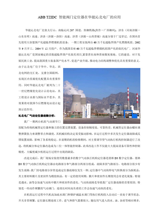
ABB TZIDC 智能阀门定位器在华能沁北电厂的应用华能沁北电厂北依太行山,南临沁河.207国道、焦柳铁路(焦作-广西柳州)、济东(河南济源-山东东明)高速、济洛(济源-洛阳)高速、济晋(济源-山西晋城)高速分别于厂边穿过。
在国内首先使用大容量国产化超临界燃煤机组设备,一期工程安装两台60万千瓦超临界国产化燃煤机组。
2002年9月开工,2004年12月投产。
作为我国首座60万千瓦超临界燃煤机组国产化的依托电厂,河南华能沁北电厂是国家确定的首批超临界国产化依托项目,紧靠晋东南和晋南煤炭基地。
它的建设,对于发展民族工业,提高我国重大装备国产化水平,促进产业升级,推动电力结构调整和优化具有重要的意义。
由于沁北电厂位于华中、华北、西北电网的交汇处,支撑全国联网,实现区内资源优化配置具有重要作用。
同时华能沁北电厂被列为二十一世纪燃煤优化设计示范电站,其工程设计水准与国际水平看齐,其效果将对我国今后燃煤电站设计起到示范作用。
沁北电厂气动定位器故障分析:我厂一期两台机组气动调节门原配为传统机械型定位器和独立的位置反馈装置,设备控制精度低,可靠性差,机械型定位器由螺丝调整弹簧张力来调整零点和满度,其机械结构决定易受振动影响,在运行过程中多次发生定位器故障或反馈装置故障,影响了各系统稳定,在前期的机组检修期间,对主要调节型气动执行机构控制器进行了改造,将机械分体定位器改造成为三位一体智能控制器,此项改造工作不仅能大大提高设备可靠性和控制精度,大幅度减少机组运行过程中出现的缺陷。
改造完成后,我厂现场安装使用数量最多的数字气动执行机构定位器是朋林D3数字定位器,朋林D3数字气动执行机构定位器由电路部分和气路部分两部分组成,故障多因气路部分,电路部分很少有发生故障,我厂因电路部分异常造成定位器故障仅发生一例。
定位器中气动块即电气转换部分为损耗品,其主要材料膜片及密封件为橡胶制品,有一定的使用周期,膜片和密封件长期使用会有老化现象,特别是遇水、油等会加速气动块中膜片和密封件的老化。
火电厂中减温水调节门采用ABB定位器发生阀位震荡的原因分析及处理办法
2018年17期方法创新科技创新与应用Technology Innovation and Application火电厂中减温水调节门采用ABB 定位器发生阀位震荡的原因分析及处理办法赵晨(中国能源建设集团东北电力第一工程有限公司,辽宁辽阳111000)引言火力发电是我国主要的发电方式,而在火力发电厂自动控制系统中,调节阀的选用对整个系统的运行至关重要,它通过智能定位器对执行机构阀位的调节使得系统的重要运行参数(温度,压力,流量等)达到一个可控的范围,满足规范要求,保证安全生产。
由我公司参与建设的宁夏煤制油自备电厂的减温水调节阀选用了ABB 公司的TZID 系列智能定位器,v3.0软件版本,该定位器采用微处理控制,具有运行精度高,操作简单易行,就地修改运行参数等特点。
本文结合了调试人员在调试减温减压器减温水调节门时发生震荡的问题,对造成此类现象的原因和解决办法做出了详细阐述。
1ABB 定位器引起阀位震荡的原因分析及处理方法1.1漏气造成的阀门震荡1.1.1气源管到定位器的连接处或定位器到阀门的管路漏气在手动控制的模式下,发现阀门阀位震荡,应取一个装满肥皂水的喷壶喷涂到气源管到定位器的连接处或定位器到阀门的管路各处,并将阀门打开到中间位置,观察是否有漏点,如有漏点,及时做好密封处理,之后保持阀门在中间位置1min ,观察阀门是否稳定。
1.1.2定位器本身的I/P 模块质量问题,自身漏气确认各连接处无漏点后,发现阀门依然震荡,将定位器输出端管路拆下,给定定位器某一个阀位值,等待1min ,观察定位器是否能够稳压,输出端是否有气流,如果发生此类情况,更换定位器内部的I/P 模块,问题将得到解决。
1.2安装和接线问题1.2.1反馈杆松动目测或用手波动一下反馈杆,使调节阀动作,然后松开,如果调节阀能回到原位,说明反馈杆正常,否则为反馈杆松动,需要重新安装反馈杆。
1.2.2定位器电路板接线柱松脱,管线或调节阀震荡时,突然间断电,瞬间又恢复轻轻拨动接线看是否有虚接松动等现象,此类定位器的接线端子是焊接到电路板上的,焊点较少,有时也会由于运输或接线时的不小心导致焊点脱开,接线端子虚接,如果出现这两种情况,需要重新接线和更换电路板,这种情况并不多见。
TZIDC-200(ABB)智能阀门定位器

s Compact and efficient,through well-proven technology and intelligences Communication based on the "HART" protocol as a standards Simple commissioning procedurethrough fully automatical Autoadjust functions Easily understandable adjustment mode,adjustment is done remotely using the standardizedconfiguration program, or (optionally) via the built-inoperator panel and displays 4...20 mA input, 2-wire, maximum voltage drop9.7 VDC at 4 mAs Explosion protection certificates, flameproof enclosure, ATEX, FM/CSAs Complies with EC directives for EMC and CE conformity s Robust aluminum case, IP 65s Influence of shock and vibration <1% with a load of up to10 g and frequencies between 20 and 80 Hzs Wide operating temperature range, - 30 to + 85 °C (-22 to +185 °F)s Stable control loop through self-adaptation and continuous modulation of the outputs Attachment to pneumatic actuators in accordance with the standard (single version for linear or rotary applications), or customer-specifics Mechanical position indicators Option pressure gage block and filter regulators Low operating cost, air consumption < 0.1 kg/hTZID-C200Intelligent positioner,compact and efficientwith flameproof enclosure10/18-0.32 ENThe conceptThe TZID-C200 positioner is an intelligent and electronically confi-gurable instrument with communication, service and diagnostic ca-pabilities, mounting to pneumatic actuators. The TZID-C200 stands out for a small and compact design, a modular construction, and an excellent cost-performance ratio.The functional heart of the TZID-C200 positioner is its micropro-cessor-controlled CPU where the operating system is running. The input signal and the position feedback signal are polled with a sam-pling rate of 20 ms and an A/D resolution of 4000 steps. This en-sures a rapid and high-precision signal processing for the input and the position feedback. The power for the CPU is derived from the set point signal.The operating program includes an Autoadjust routine for automa-tic adjustment of the device in the commissioning phase, and an adaptation program which provides for optimal control of the posi-tion to minimize control deviation.The pneumatic actuator is driven by an I/P module with subse-quent 3/3-way valve. The electrical positioning signal from the CPU is proportionally converted into a pneumatic signal which, in turn, proportionally adjusts the 3/3-way valve. The cross-sectional area of the valve air channels for filling the actuator with air or eva-cuating air from it is changed in proportion with the adjustment. When reaching the set point, the 3/3-way valve is closed in center ually, the TZID-C200 positioner is configured, commissioned and monitored remotely from a PC via its communication port, using the HARTâ protocol. You can either tap at a local connector, or frequency-modulated at any chosen point of the 4...20mA si-gnal line. Optionally, the integated operating panel and display can be used for local control.The modular design of the positioner allows you to add further functionality at a later time. Plug-in modules for analog and digital position feedback as well as assembly kits for mechanical position indication and digital position feedback using proximity switches or 24 V microswitches are available. Additionally, the plug-in module for the shutdown function is available.Various TZID-C200 features ensure safe valve operation on site: s Compliance with the EMC directives Robust aluminum case, protection IP 65 (NEMA 4X)s Immunity to shock and vibration up to 10 gs Operational reliability through permanent monitoring and error indication in case of troubless Operation at ambient temperatures of -30...+85 °C (-22...185 °F)s Leakage and configurable preventive maintenance alarmsPage 2 of 1701.02MountingTo linear actuators in accordance with the standardLateral attachment is in accordance with DIN/IEC 534 (lateral at-tachment to Namur). The attachment kit required for lateral attach-ment is a complete set of attachment material, except for screwed pipe connections and air pipes.To rotary actuators in accordance with the standard Attachment to rotary actuators is in accordance with VDI/VDE 3845. The attachment kit contains two items: the adapter for cou-pling the positioner feedback shaft to the actuator shaft, and a mounting bracket for mounting the positioner to the actuator. Scre-wed pipe connections and air pipes are not included in the kit and have to be provided by the customer.Integral mounting to control valvesSome actuators allow for integral mounting and have been prepa-red for special attachment of the positioner. The benefits of this de-sign are that, on one hand, the point for mechanical stroke measu-rement is inside the yoke and, thus, protected by it, and, on the other hand, no external tubing is required, since the air flow from the positioner to the actuator is guided through an internal channel bore.Special actuator-specific mountingIn addition to the mounting methods described above, there are special actuator-specific attachments.Please contact us for details.01.02Page 3 of 17GeneralWith its operating program the intelligent microprocessor-control-led TZID-C200 positioner is best suited for achieving optimal resul-ts - both in terms of rapid and precise control until reaching the set point and in terms of a high operational reliability. The activation and adjustment of parameters necessary to achieve this goal is in parts automatic (auto-adjustment) and in parts manual.The total range of parameters includes:–Operating parameters–Adjustment parameters–Monitoring parameters–Diagnostic parameters–Preventive maintenance parametersOperating parametersThe following operating parameters can be activated and adjusted:–Signal rangeIt can be selected whether the full range of 4 .. 20 mA or asplit-range is to be used.–Valve actionDirect:Range 4...20 mA/direction 0...100 %Reverse:Range 20...4 mA/direction 0...100 %–Characteristic curve (travel = f {pos. signal})linear,equal percentage 1:25 or 1:50 or 25:1 or 50:1,or user-configurable with 20 reference points–Tolerance band (sensitivity limit)The factory setting of 0.3 % is a typical value, which only has to be increased in case of very short strokes or high hystere-sis values of the valve. Normaly, the controller automatically optimizes itself during the Autoadjust function.–Travel limitingThe positioning travel, i.e. the stroke or angle of rotation, can be reduced as required within the full range of 0...100%,provided that a minimum value of 20% is observed.–Shut-off valueThis function causes immediate closing of the actuator. The threshold can be configured.–Time-out monitoringThis function is used to monitor the time needed to reach the set point. It triggers an alarm if the unit is not able to adjust the deviation such that it fits into the tolerance band withinthe set time.–Adjusted speed for full travel 100 %This function is used to increase the natural speed for con-trolling the full travel until reaching the set point. The speed can be set independently for each direction.–Stroke counter and travel counter–Alarm limits for minimum and maximum positionsThis parameter is used to define the switching points for the minimum and the maximum position.–Digital inputWith the digital input you can disable or limit configurationaccess or directly adjust the actuator byholding the current actuator positionorsetting the actuator to the 0% or 100 % positionAdjustment parametersThe following parameters can be activated and adjusted:–Valve range 0...100 %Valve end positions, start of range "0%“ and end of range"100 %".–Effective direction of the actuatorAdjustment to either of the two possible directions:Air to open/spring force to closeorAir to close/spring force to open–Display 0...100 %Adjusting the display (0...100 %) to the direction of action for opening or closing the valve.–Control parametersTo adapt the TZID-C200 positioner to the control action ofthe valve, the control parameters can be adjusted individually to achieve optimal control until reaching the set point.The TZID-C200 positioner has a program (Autoadjust) for auto-matic adjustment of all relevant parameters. The Autoadjust routi-ne can be started by pressing the respective push-buttons on the device’s front panel (option).Page 4 of 1701.02Monitoring parametersThe TZID-C200 operating system allows for permanent self-moni-toring. The following list gives some examples for errors that are detected and can be indicated:–Watchdog alarm–Leakage in the actuator or air pipe from / to it–Signal out of 4....20 mA range–Position out of adjusted range (rotation angle) for positionfeedback–Positioning time-out (adjustable time parameter)–Limit of stroke counter or travel counter exceeded(limits can be adjusted during diagnosis)If any of these disturbances occurs, an alarm is generated and in-dicated as an error code on the option LC display, or reported as a collective alarm via the digital output.Extended monitoring is possible via the communication port. The most important process variables like the output signal in mA, the position in %, the deviation, and troubles occurring during opera-tion are indicated as plain text in a special line.The operator panel (option) consists of an LC display and four push-buttons (see the illustration to the right).The TZID-C200 positioner operator panel alllows for–monitoring–manual control–TZID-C200 configuration (all operating data, except for the user-configurable characteristic curve with 20 referencepoints)The display indicates the following data:–Current process value or parameter number,shown by the upper, 4-digit segment display–Designator / name of indicated parameter or value,shown by the lower, 8-digit segment display–TZID-C200 operating status, indicated by the following sym-bolsshown on the left hand side of the displayLocal configuration is disabledAutomatic control through the TZID-C200Position is adjusted manuallyby actuating the Ý and ß push buttons conf TZID-C has been changed over to theconfiguration level, control is interrupted –On the operating level, i.e. while either automatic control is in progress or the TZID-C200 is ready for manual position ad-justment, the upper 4-digit 7-segment display indicates the position as a percentage (0...100 %). If an operating errorshould occur, the display changes over to an error code (see "Monitoring parameters" for details).Diagnosis parametersThe diagnosis parameters of the TZID-C200 program inform the operator about the operating conditions of the valve. From this in-formation the operator can derive which maintenance works are required, and when. The parameters also provide information about the use of the valve and, thus, its possible wear.The following values are determined:–Number of control actions performed by the valve–Total stroking distanceThe diagnosis parameters can be set externally, i.e. via the com-munication port, by using the special TZID-C200 configuration program.Operation01.02Page 5 of 17GeneralThe TZID-C200 communication port allows for remote operation, monitoring and configuration.The "HART‚" Protocol is used for communication. Signals can be tapped either locally at the connector or frequency-modulated at any chosen point of the 4...20 mA signal transmission. Communi-cation is done on line, without impairing operation. New parameter settings become active immediately after being downloaded into the device, but have to be stored in the TZID-C200 non-volatile memory with a special command.The following equipment is needed for communication:–a special connecting device(LKS adapter or FSK modem)–an off-the-shelf PC(meeting special hardware requirements)–a program for remote control and configuration(e.g. SMART VISION®)LKS adapter as a communication linkThe LKS adapter is a connection solution which is both easy to in-stall and cost-saving. On the TZID-C200 side, a local communica-tion interface (LKS) is used. On the PC-side, a double sub-D jack with a 9-pole and a 25-pole connector is used. The connector also accommodates an RS-232 interface converter for connection to the PC.The TZID-C200 can be configured via LKS without requiring that a 4...20mA signal is fed to it. As a result, this kind of configuration can be performed in the workshop prior to commissioning. In this case the positioner is powered by the PC.FSK modem as a communication link (HART)The FSK modem is used to establish digital frequency-modulated communication (F requency S hift K eying). The digital signal "0" corresponds to 2.2 kHz, the digital signal "1" to 1.2 kHz. Tapping is possible at any chosen point of 4...20mA transmission, i.e. directly on site at the TZID-C200 or in a remote place, e.g. at a PCS in the control room. Frequency-modulated communication re-quires a circuit with a resistance of at least 250 ohms.The FSK modem is available in 2 versions: with or without electri-cal isolation. In conjunction with a special isolating amplifier, e.g. Contrans I or Contrans I_remote, the modem with electrical isola-tion is suitable for connection to a bus. Communication is also pos-sible with an intrinsically safe TZID-C200, provided that the mo-dem itself is placed outside the hazardous area. If these capabilities are not required, you can also use the cost-saving mo-dem without electrical isolation (FSK Modem II).For details and technical data refer to the data sheet 63-6.71 EN.OperationPage 6 of 1701.02Communication and special program for remote control and communicationSMART VISION®SMART VISION®is a windows-type graphical user interface with user-friendly and intuitively operable standardized windows. SMART VISION® offers comfortable functions for configuring, monitoring and diagnosing the TZD-C200 positioner.The program has the same "look" as MS Windows, i.e. it has sim-ilar intuitively operable windows, and commands can be entered in the same way. Users familiar with MS Windows can easily adapt to SMART VISION®.The SMART VISION® communication program can be used with all our HART-compatible devices. Due to its open structure, SMART VISION® is ABB’s communication platform for all products using HART. Pull-down menus and predefined commands allow easy configuration, service, and maintenance.Please contact us for details.Hardware requirementsFor details see data sheet 63-1.20 EN HART CommunicatorThe compact HART communicator Type 275 (from Fisher Rose-mount) can be used for operating the TZID-C200 positioner via the FSK modem, using the HART Protocol. This is another way of con-trolling the positioner locally, adding up to remote control via the PC and configuration program, or local control using the operating panel and display (option).Manual configurationIf required, the TZID-C200 positioner can be operated by using the integrated 4-key operating panel and LC display. Local operation is even possible in hazardous areas and while operation is in progress. The operating panel is placed under a lid in the enclo-sure cover and, thus, protected against harsh environmental con-ditions.Typical SMART VISION® window01.02Page 7 of 17Technical dataInputSignal rangeNominal range 4...20 mASplit range configurable between 10...100 % of nominal range Overcurrent protection 25 mA / 30 VTwo-wire circuitryMax. voltage drop9.7 V DC at 4 mAResistance485 ohms at 20 mADigital inputControl voltage12...24 V DCCurrent max. 4 mAOutputRange0...6 bar (0...90 psi)Air capacity5.0 kg/h = 3.9 Nm3/h = 2.3 scfm at 1.4 bar (20 psi) suppl. pressure13 kg/h = 10 Nm3/h = 6.0 scfm at 6 bar (90 psi) suppl. pressure(Booster, increases air capacity, available on request)Option spool valveOutput range 0...7 bar (0...100psi)Air capacity 45kg/h = 20.0 scfm at 7bar (100psi)Air consumption > 1.2 kg/h / 0.6 scfmFunctionfor single or double acting actuators, air is vented fromactuator or actuator is blocked in case of el. power failure;Note: special situation with spool valve optionShut-off valueRange 0...20 % of positioning signal(if the value falls below the set value, the positioner immedi-ately moves the actuator to the closing position)Digital output (control current circuit to DIN 19234)Control voltage 5...11 VDCCurrent < 1.2 mA Logical "0"Current > 2.1 mA Logical "1"Effective direction:Normally logically "0" or "1"(config.)TravelAngle of rotationUsed range25...120 °, optionally 270 °Adjusted speedRange 0...200 sec, configurable for each directionTime-out monitoringRange 0...200 sec (monitoring parameter for control until the deviation is within the tolerance band)Travel limitingMin. and max. limits,freely configurable within 0...100 % of the total travelAir supplyInstrument airfree of oil, water and dust to DIN/ISO 8573-1pollution and oil contents according to Class 3dew point 10 K below operating temperatureSupply pressure1.4...6 bar (20...90 psi)Special situation with spool valve:1.4...7 bar (20...100 psi)Caution: Observe the actuator’s maximum operating pressure! Air consumption< 0.1 kg/hSpecial situation spoole valve:< 1.2 kg/h Transmission data and influencesDirection (output signal or pressure in the actuator)Increasing:Increasing signal 4...20 mAIncreasing pressure y1 in the actuator Decreasing:Increasing signal 4...20 mADecreasing pressure y1 in the actuator Valve actionDirect:Range 4...20 mA = position 0...100 %Reverse:Range 20...4 mA = position 0...100 % Characteristic curve (travel = f ísignalý)linear, equal percentage 1:25 or 1:50 or 25:1 or 50:1and freely configurable with 20 reference points Characteristic deviation< 0.5 %Tolerance band (sensitivity limit)0.3...10 %, adjustableResolution (A/D conversion)> 4000 stepsSample rate20 msecInfluence of ambient temperature< 0.5 % for every 10 K change in temperatureInfluence of vibration+ 1% up to 10 g and 20...80 HzSeismic requirementsMeets requirements of DIN/IEC 68-3-3 Class III for strong and strongest earthquakesInfluence of mounting orientationNo effectComplies with the following directivesEMC directive 89/336/CEE as of May 1989EC directive for the CE conformity certification CommunicationFSK HART protocol (stand.)Communication link via connector for LKS adapter (standard)Environmental capabilitiesAmbient temperature-30...+85 °C (-22...185°F) f. operation, storage and transport (-40°C / -40°F under preparation)Relative humidity< 95 % , non-condensingExplosion ProtectionEx II 2G EEx d IIC T4, T5, T6 / ATEXFM/CSA Cl. 1 Div. 1 Group B-GEx ib / ATEXFM/CSA intrinsically safeOther explosion protection certificates upon requesttEnclosureMaterial/surfaceAluminum, protection IP 65 (NEMA 4X)Bottom part of case varnished black, RAL 9005, matt,Cover light gray, RAL 9002Cap Pantone 420Electrical connectionsScrew terminals, internal, for CSA of 2.5 mm2Cable entry: threads M20 x 1.5 or 1/2-14 NPTPneumatic connections: Threads G 1/4 or 1/4-18 NPTWeight: 3kgMounting orientation: as requiredDimensions:see dimensional drawingsPage 8 of 1701.02OptionsIntegrated operating panel and displayThe 4-key operating panel and the 2-digit LC display can be in-tegrated in the device . Please note that this is no retrofit kit. Plug-in module for analog position feedback *)Signal range 4...20 mA (split ranges configurable)2-wire circuitry, power supply 10...30 V DCValve action direct or reverse (configurable)Characteristic deviation < 1 %(the module can be configured for alarm reporting throughmodulation of the output signal to < 4 mA or > 20 mA)Plug-in module for digital position feedback *)2 switches for the min. and max. positions(switching points programmable within a range of 0...100 %) Current circuits to DIN 19234Control voltage 5...11 V DCControl current < 1.2 mA= switching state logical "0"Control current > 2.1 mA= switching state logical "1"Effective direction:normally logical "0" or logical "1" (config.) Plug-in module for the shutdown function*In case of a 24 V DC power failure, the positioner can let the valve move to the safe position by depressurizing the actuator independently of the processor. To achieve this, the I/P module power supply is separated by an optocoupler. Both the commu-nication and feedback are still active, since the positioner is powered via the 4...20mA 2-wire cable. The shutdown input is electrically isolated from the 4...20mA signal.Due to the shutdown function no additional solenoid valves are required. It has a safety certificate from TÜV Rheinland in ac-cordance with AK4. The plug-in module also has an Ex certifi-cate for use in intrinsically safe current circuits.Spoole valve (sliding valve)Pneumatic output unit for output range of 0...7bar (0...100psi) Air capacity 45 kg/h at supply pressure of 7 bar (100 psi)Air consumption < 1.2 kg/h(switching points adjustable within a range of 0...100 %)Kit for mechanical position indicatorIndicator disk in enclosure cover, linked with feedback shaft of the positioner through magnetic couplingKit for digital position feedback with proximity switches2 proximity switches for min. and max. position(position adjustable within range of 0...100%)Current circuit to DIN 19234Supply voltage 5...11 V DCControl current < 1 mA= switching state logical "0"Control current > 3 mA= switching state logical "1" (works inde-pendently of the software and the electronics of the positioner) Direction of action (logical state):Kit for digital position feedback with 24 V microswitches Two 24V DC/AC microswitches for the min. and max. position.Switching points adjustable between 0 and 100 %Not approved for use in the hazardous areas! Do not use microswitches in an Ex ia type device.*The plug-in modules for analog and for digital position feedback are plugged in different slots and can be installed together. The plug-in mod-ule for the shutdown function, however, cannot be used with the module for analog feedback nor with the digital position feedback module.Mounting materialAttachment kit for linear actuators to DIN/IEC 534 / Namur Attachment kit for rotary actuators to VDI/VDE 3845Attachment kit for integral mounting to control valvesAttachment kit for actuator-specific attachment upon request Pressure gage blockWith pressure gages for supply and output pressure,Pressure gages with plastic case Æ 28 mm,with aluminum connection block, varnished blackinclusive of mounting material for attachment to TZID-C200. Filter regulatorAll metal version, brass varnished blackBronze filter element, 40 µm, with condensate drainMax. pre-pressure 16 bar, output adjustable to 1.4...6 bar Separate cable gland for feedback cableThis cable gland is required if the cables of a retrofitted option module are to be laid separately from the 4...20 mA signalcable.PC adapter for communicationLKS adapter for connector on TZID-C200,see data sheet 63-6.71 ENFSK modem for frequency shift keying,see data sheet 63-6.71 ENHand-held terminal (HHT) for HART communication Type 275 (from Fisher Rosemount)PC software for remote configuration and operation SMART VISION‚ CD ROM (see data sheet 63-1.20)Spare parts kitTool kitSlot-typeinitiatorPosition< min. > min. < max. > max.SJ2-SN (NC) 0 1 1 0SJ2-S1N (NO) 1 0 0 1Accessories01.02Page 9 of 17Page 10 of 1701.0201.02Page 11 of 17Page 12 of 1701.0201.02Page 13 of 17Wiring diagramsPage 14 of 1701.0201.02Page 15 of 17Page 16 of 1701.0201.02Page 17 of 17ABB Automation Products GmbH Schillerstrasse 72D-32425 MindenPhone:+49(0)57 18 30 - 0Fax:+49(0)57 18 30 - 18 60 Subject to technical changes Printed in the Fed. Rep. of Germany10/18-0.32 EN01.02。
二次风执行机构控制系统改造及应用

二次风执行机构控制系统改造及应用论述300MW机组锅炉二次风执行机构控制系统的构成原理以及在运行过程中出现的问题分析和判断,并进行了设备的改造和相应气控柜及逻辑的改进。
通过文章的分析,希望对相关工作提代供帮助。
标签:二次风;定位器;控制;改进1 概述二次风使煤粉、空气充分混合,同时供给煤粉及燃油所需的助燃空气。
二次风气动控制装置根据锅炉负荷变化和燃料的变化来控制二次风挡板。
为了有效地保证锅炉燃烧和维持炉膛负压一定,一般二次风挡板开度大小通过燃烧器管理系统控制。
挡板开关位置的指令信号通过煤层和油层启停过程中的协调控制系统来实现。
根据二次风起着不同的作用,二次风分为辅助空气、燃料和助燃风,通过不同的方式分别进行控制,AA、A、AB、B、BC、C、CD为7层下部二次风,CD2、D、DE、E、EE1、EE2为6层上部二次风。
2 智能定位器控制原理现场控制柜接受由DCS系统给出的4-20mA指令信号,压力信号是通过控制柜中的智能定位器到相应气缸上、下缸进气压力的调节分布,连续线性调节气缸,使气缸在整个范围内任意0-100%精确调整。
同时,该执行机构的位置变送器的位置将被转换为4-20mA标准信号回传至智能定位器,再通过一个4-20mA 反馈信号功能模块的智能定位器的反馈,然后发送到DCS。
每4套执行器的控制部分被集成了一个控制柜,其中每一层作为一个实际应用的控制柜,四角同动。
3 原二次风执行器控制存在问题在热工人员长时间设备维护过程中发现机械式定位器控制精度低,执行机构卡涩、开关不灵活、出现不等的响应时间等问题,而且调试过程繁琐,反馈信号漂移不稳定,经常出现超调或不调而引起的DCS显示坏点。
同时执行器所处的安装的位置不易维护,给锅炉燃烧运行所需的调节空气的调节造成了很大的影响,带来了安全隐患,影响锅炉燃烧效率。
二次风门气动执行器的控制模式是不合理的,一个电气转换器控制一层四个二次风门,不能满足安全生产的需要,一旦其中一个二次风门故障,会导致同一层的三个二次风门失控,极大地影响了锅炉的稳定燃烧。
二次风
300MW机组锅炉二次风门控制方式探讨2010-11-12 13:56:55 来源:中国计量测控网点击率:15947 字号: 摘要:本文通过对呼和浩特金山电厂和华润金能热电锅炉二次风门采用的不同控制方法进行论述,提出了锅炉二次风门控制宜取消就地气控柜直接由DCS控制,所有控制逻辑由DCS软实现。
一、概述燃烧器是锅炉的燃烧设备,其作用是保证燃料和空气的充分混合、及时着火和稳定燃烧。
通过燃烧器送入锅炉的空气是按对着火、燃烧有利的原则合理组织,分别送入的。
按送入空气作用的不同,可以将送入的空气分为一次风、二次风等,其中二次风是煤粉着火后再送入的空气,又分为辅助风、燃料风和燃尽风。
辅助风是二次风的主体部分,其作用是维持炉膛和二次风箱之间所需的静压差。
风箱与炉膛之间的压差设定值是负荷的函数。
辅助风控制系统为一单冲量多输出控制系统,它根据风箱与炉膛之间的压差以及燃烧器管理系统BMS来的指令,并行控制多层辅助风挡板,以维持炉膛和二次风箱之间的压差在设定值上。
运行时根据各层磨煤机负荷的不同而需要不同的配风,每层辅助风挡板都设有操作员偏置站。
当油枪处于程控点火位置时,对应的辅助风挡板处于“油枪点火”位置。
当锅炉处于启动阶段吹扫之前或停炉后,辅助风挡板应全开。
锅炉吹扫完成后,辅助风挡板应处于“压差控制方式”。
燃料风又称周界风,其作用是供给一次风煤粉气流以适当的空气,补充由于煤粉高度集中在燃烧初期可能出现的氧量不足。
调整好燃料风以利于煤粉气流着火和燃烧的扩展。
燃料风通常与给粉量成正比,燃料风挡板一般不设计操作器。
每层燃料风挡板的开度信号由对应的给煤机速度信号经函数发生器给出。
如某台给煤机速度小于最小允许给煤量时,相应层燃料风挡板应全关。
当BMS发来“关闭燃料风挡板”信号时,燃料风挡板应全关。
当辅助风控制系统发来“打开燃料风挡板信号”或BMS发来“打开燃料风挡板”信号时,燃料风挡板应强制全开。
燃尽风又称顶二次风。
它从燃烧器的最上层的一个二次风喷口引入炉膛。
ABB智能定位器使用说明
概述定位器的作用使风门、档板按照运行人员的意愿动作,使被调对象达到要求的范围,使设备达到安全运行。
菏泽电厂原设计使用F40、F20的风门档板都是风、烟系统上的重要设备,如送风机入口冷风、暖风调节档板,六个二次风调节档板,炉底注入风调节档板、磨煤机热风、冷风调节档板、磨煤机旁路风调节档板,这些设备运行状况的好坏,涉及到重大辅机的保护、跳闸问题,使机组降出力,严重时使锅炉燃烧不稳定,导致锅炉灭火,甚至毁坏设备。
英巴公司对此问题也进行了表态,承认F40、F20定位器质量不可靠。
通过了解聊城电厂F40、F20定位器使用情况,和我厂情况一样,故障率特别高,曾经给机组的安全稳定运行构成不同程度的威胁,聊城电厂已将F40、F20定位器全部更换成ABB定位器,效果有明显改善,风门、档板控制的工况更加稳定,保证了机组的安全运行。
因此为保证我厂机组的安全稳定高效运行,将F40、F20定位器改造成质量较可靠的双端控制输出气源ABB定位器。
ABB定位器在我厂的其它设备上已经长时间使用,工作稳定,故障率底,调节特性灵敏,深受电厂单位的青睐。
目前#4炉所用的F40和F20两种类型的I/P电气转换器经常出现堵塞、漏气、反馈信号不可靠、线性不好等缺陷,使风门、档板无法按照运行人员的意愿动作,使风门、档板失控,导致风门、档板要么拒动,要么全开全关,使被调工况超出允许范围,直接威胁机组的安全运行,英巴公司对此问题表态,承认F40、F20定位器质量不可靠,为保证机组的安全稳定运行,将F40定位器改造成质量较可靠的双端输出气源ABB定位器。
将F40定位器改造成质量较可靠的ABB定位器,使风门、档板按照运行人员的意愿动作,使被调对象达到要求的范围,使设备达到安全运行。
F40改造成ABB定位器,只需加工ABB定位器与现气缸连接转换接头,再将ABB定位器通过转换接头安装在现气缸上,将气源管路配接牢固,和机务重新定位调试。
1 F40型I/P电气转换器F40型定位器是通过将微处理器技术与气动控制装置电气接口有机结合起来,最基本的型号为2线式仪器,一个工业标准的20mA信号既用作控制信号,又用作电子线路的电源,通过插接接头可进行连接,微处理器的采用使设置操作变得非常简单、迅速。
ABB TZID-C智能定位器快速分体改造在火力发电厂二次风门中的应用
ABB TZID-C智能定位器快速分体改造在火力发电厂二次风门中的应用发表时间:2017-05-16T16:06:34.707Z 来源:《电力设备》2017年第4期作者:丁建立[导读] 摘要:火力发电厂锅炉的二次风门(或称小风门)是燃烧控制的重要子系统,用于助烧,控制低NOx的产生等。
(厦门华夏国际电力发展有限公司 361026)摘要:火力发电厂锅炉的二次风门(或称小风门)是燃烧控制的重要子系统,用于助烧,控制低NOx的产生等。
二次风门气动智能定位器及执行装置大部分直接一体式安装在炉膛壁上,以ABB TZID-C系列为代表的二次风门定位器控制系统应用广泛,但安装位置过于狭窄,面临高空作业,更换非常不便。
高温导致定位器端盖变形,强制割开后复装对于防雨防尘均带来挑战。
将原有的一体化ABB TZID-C系列智能定位器进行快速分体化改造,保留原来的定位器外壳及位置传感器,最大限度地减少工作量及安装成本,可以有效的解决上述问题。
关键词:二次风门;小风门;智能定位器;快速分体改造;TZID-C1.设备概况某电厂 4号机组(300 MW)锅炉为上海锅炉厂产1025 t/h、亚临界、汽包循环、单炉膛、一次再热、固态排渣、全钢架悬吊结构锅炉,配置 5 套制粉,通过混合一次风将煤粉直接吹入炉膛燃烧。
二次风量控制原有14层气动门(含摆角),低氮燃烧改造后,减少为11层,增加低氮燃烧SOFA风4层及SOFA摆角1层,系统均等配风,四角切圆燃烧。
全部的16层风量全部采用ABB TZID-C系列智能双作用定位器(以下简称TZID-C定位器)控制来实现。
2.二次风门控制系统概述锅炉二次风是提供煤粉及油燃烧所需的助燃空气,使煤粉、空气充分混合。
二次风门气动控制装置根据锅炉负荷及燃料投切情况对二次风挡板进行控制。
正常运行时二次风挡板开度大小由燃烧器管理系统控制,由现场的TZID-C定位器执行,从而保证稳定的燃烧和一定的炉膛负压,保证NOx浓度在合理范围内,符合环保要求。
气动执行器分体定位器在火力发电厂中的应用
气动执行器分体定位器在火力发电厂中的应用作者:倪平赵四海王晓俊来源:《硅谷》2015年第02期摘要华电内蒙古能源有限公司包头发电分公司(以下简称“华电包头公司”)2012年通过技术改造将除氧器水位调节阀、锅炉过热器减温水调节阀、二次风挡板等气动执行器定位器改为分体式定位器,改造后设备可靠性大大增强,本文就气动执行器分体式定位器在火力发电厂中的应用进行了详细阐述,具有很强的推广性。
关键词分体执行器;可靠性;技术改造中图分类号:TP212 文献标识码:A 文章编号:1671-7597(2015)02-0259-012006年内蒙古包头投产了2×600MW亚临界火力发电厂,就是现在的华电包头公司,他的DCS控制系统是以英维思Foxboro I/A51为控制系统的。
锅炉过热器减温水调节阀执行器、二次风挡板、除氧器水位调节阀均采用气动执行器控制阀门开度,气动执行器定位器为西门子智能一体定位器,由于该机组的定位器电路板受高温影响而导致了定位器无法正常工作,这样就会引起一系列连锁反应:降低设备可靠性→整个机组运行不稳定,又因为定位器为智能的且是一体化的,无法单独维修,智能更换定位器,智能定位器价格昂贵,维护费用较高,运行工作人员在执行器发生故障后需手动操作,不仅达不到最佳的控制效果,也加大了运行操作的工作量。
因此,为提高设备的可靠性、减少设备维护和检修费用,所以需要将定位器进行改造,由以前的整体式改为分体式。
1 气动执行器、定位器改造前的故障分析本公司使用一体化的智能定位器作为调节型气动,通过DCS系统发送到定位器指令而实现执行器控制功能,绝大部分定位器出现故障都是因为控制电路板出现问题而导致损坏,因为其为集成一体化电子产品,所以一旦故障出现无法现场进行维修,所以在发生故障后只能通过换用新的定位器来消除故障。
导致定位器发生故障的原因主要有以下两个方面:一是由于定位器长期处于高温工作环境下,使得其迅速老化并容易产生故障。
- 1、下载文档前请自行甄别文档内容的完整性,平台不提供额外的编辑、内容补充、找答案等附加服务。
- 2、"仅部分预览"的文档,不可在线预览部分如存在完整性等问题,可反馈申请退款(可完整预览的文档不适用该条件!)。
- 3、如文档侵犯您的权益,请联系客服反馈,我们会尽快为您处理(人工客服工作时间:9:00-18:30)。
ABB TZID-C智能定位器快速分体改造在火力发电厂二次风门
中的应用
摘要:火力发电厂锅炉的二次风门(或称小风门)是燃烧控制的重要子系统,
用于助烧,控制低NOx的产生等。
二次风门气动智能定位器及执行装置大部分直
接一体式安装在炉膛壁上,以ABB TZID-C系列为代表的二次风门定位器控制系统
应用广泛,但安装位置过于狭窄,面临高空作业,更换非常不便。
高温导致定位
器端盖变形,强制割开后复装对于防雨防尘均带来挑战。
将原有的一体化ABB TZID-C系列智能定位器进行快速分体化改造,保留原来的定位器外壳及位置传感器,最大限度地减少工作量及安装成本,可以有效的解决上述问题。
关键词:二次风门;小风门;智能定位器;快速分体改造;TZID-C
1.设备概况
某电厂 4号机组(300 MW)锅炉为上海锅炉厂产1025 t/h、亚临界、汽包循环、单炉膛、一次再热、固态排渣、全钢架悬吊结构锅炉,配置 5 套制粉,通过
混合一次风将煤粉直接吹入炉膛燃烧。
二次风量控制原有14层气动门(含摆角),低氮燃烧改造后,减少为11层,增加低氮燃烧SOFA风4层及SOFA摆角
1层,系统均等配风,四角切圆燃烧。
全部的16层风量全部采用ABB TZID-C系列智能双作用定位器(以下简称TZID-C定位器)控制来实现。
2.二次风门控制系统概述
锅炉二次风是提供煤粉及油燃烧所需的助燃空气,使煤粉、空气充分混合。
二次风门气动控制装置根据锅炉负荷及燃料投切情况对二次风挡板进行控制。
正
常运行时二次风挡板开度大小由燃烧器管理系统控制,由现场的TZID-C定位器执行,从而保证稳定的燃烧和一定的炉膛负压,保证NOx浓度在合理范围内,符合
环保要求。
某电厂4号锅炉燃烧器低氮改造后的喷嘴布置情况如下:
每角共14层喷嘴,5层一次风喷嘴,6层二次风喷嘴,4层SOFA燃尽风喷嘴。
另外包括1层燃烧器大摆角,1层SOFA喷嘴摆角。
3.TZID-C 智能定位器简介
TZID-C 智能定位器是安装在气动执行器上的具有丰富功能新一代定位器,智
能化程度高,调节方便。
TZID-C的核心是微处理器 CPU,采用 4-20mA 输入信号
电流,反馈4-20mA给DCS系统。
能自动调整参数的自整定程序,用于精确定位的优化控制操作,通过带三位
三通放大器的电气转换器驱动气动执行机构。
从 CPU 发出的定位电信号比例地转
换成气信号,再成比例地调节气动开关的流道截面,气体从定位器输出至气动执
行器及气体的排放量均成比例地调节。
当达到设定定位值时,气动开关锁在中间
状态,因此耗气量很少。
TZID-C定位器的主要部件有:A、主控板;B、模拟量输出板;C、IP模块;D、可选的数字量输出板,反馈板等;E、定位器外壳及位置传感器。
TZID-C定位器配有的主控板,包括两排 LCD 显示器及 4 个按键。
操作键盘的
优化设计适用于就地组态,调校及监测。
采用模块化的设计,可以后期增减附加
功能模件,有故障只需更换相应模块即可。
只要插入相应的模件,既可实现模拟
及数字反馈功能。
可以安装专业设计的角度反馈板将气缸的角度信号反馈给主控
制板。
现采用的是双作用、故障闭锁V18345-10105**及双作用、故障安全V18345
-10104**两种TZID-C定位器。
两种内部IP模块有所区别。
4.常见故障及面临的问题
虽然TZID-C定位器拥有诸多优点,但在现实使用中依然面临如下问题:
4.1原来的二次风门带背板及带压力表的多组件设计,安装较为复杂,零件多,整体更换拆装不方便,耗时耗力;
4.2 超65%以上二次风门处于悬空位置,部分维护空间小,有些地方螺丝刀都
不好使;
4.3 仪用气品质差时,带油严重,对电路板、密封圈及IP模块腐蚀,故障率
增加不少。
仪用气系统未彻底改造前,只能更换定位器或部件,工作量较大。
5.ABB TZID-C智能定位器快速分体改造
鉴于二次风门的安装现状,锅炉本体已不能进行大的改造,为了尽量减少工
作量,采用将主控板、模拟量输出板以及IP模块从定位器移到分体控制箱方案
(1个箱体可以改2个TZID-C定位器),就地保留原来的定位器外壳及反馈元件,原来的指令、反馈电缆保留在定位器内部。
(如图1所示)
在就地定位器壳体中安装一块转接远控板A,将信号通过专用分体电缆接到
分体控制箱内的转接远控板B,各信号再分别接到主控板、模拟量输出板。
从现场过滤减压阀引出一路仪用气至分体控制箱,再分成两路引出到2个IP
模块底座,各自的OUT1,OUT2气路引出至二次风门气缸前后接口。
气管可以是
软性金属管或者PU气管,快速完成布管安装。
分体控制箱位于锅炉位置方便的位置,拼接安装或者焊接安装固定,在分体
控制箱就可对相应的二次风门进行控制。
5.1 TZID-C定位器快速分体后的工作流程
DCS系统过来的4~20mA指令信号先发到新安装的定位器内的转接远控板A,指令信号和位置传感器信号同时通过专用分体电缆传输到转接远控板B,再转到
主控板,主控板经过分析判断后形成控制指令控制IP模块输出气路信号,通过气
管Out1、气管Out2控制气缸运动,同时主控板通过模拟量输出板将4~20mA反
馈信号通过专用分体电缆传回转接远控板A,进而返回DCS系统,完成一个完整
的控制回路。
5.2 TZID-C定位器快速分体改造的优点
经过对就地TZID-C定位器快速分体改造后,大大方便了调试和检查工作,位
于高空中的位置传感器及转接远控板A基本没有维护量,减少了大量的高空维护
工作。
主要的电子元件集中在安全可靠的分体控制箱内,即使仪用气品质差也可
以迅速排出,避免了之前的积油现象。
这次快速分体法最大程度地保留了原来的
电缆管线,减少了对电缆桥架的拆装工作,大大节约了时间精力。
在分体控制箱
固定的前提下,采用PU管及快速接头半小时内即可完成一套定位器的分体工作。
甚至对于运行的机组,在碰到有定位器故障时,也可在最快的时间内完成一套改装,比整体更换定位器更为便捷。
6结束语
经过对某厂#4机组ABB TZID-C智能定位器快速分体改造,经过运行实践证明
该快速分体改造后的定位器系统可以满足对锅炉二次风挡板开度的精确控制,锅
炉的燃烧更加充分,同时降低了NOx浓度,提高了燃烧效率,使锅炉更加经济、
环保地运行。
大幅度降低了二次风门控制系统故障率,减少了维护量及高空作业
时间,节约了成本,且定位器位置传感器部件和主体控制分开安装,避免了高温、粉尘、受限空间等恶劣环境的影响,也减少了仪用气品质差带来的不利影响。
参考文献:
[1] 王俊杰,银伟,智能定位器在二次风门气动分体控制系统中的应用内蒙
古电力技术 2007年第25卷第3期
[2] 张玲,赵文栋,张建刚二次风系统风门执行机构改造内蒙古电力技术2010 年第28卷第2期
作者简介:
丁建立(1983—),男,湖南邵阳人,自动化工程师,研究方向:火电热控,35782035@。