吉普自由光天鉴电动尾门安装说明书样本
汽车车库门电动开关器安装与使用说明书

S M A N U As of date of manufacture, meets all ANSI/UL 325 Safety Requirements for Vehicular Garage Door OpenersM A N U A L C A R E F U L L Y B E F O R E I N S T A L A T I O N O R INSTALLER: Place this manual in the plastic envelope provided andpermanently attach to the wall near the pushbutton.Product Features....................................................2 Tools Required/Component Identification.....2 & 3 Assembly Instructions...........................................3 Identify Your Door Type.........................................4 Important Installation Instructions........................5 Installing the Opener..............................................6 Mounting the Front Bracket............................6 Mounting the Power Head...............................7 Using the Manual Release Mechanism...........7 Installation......................................8 Requirements/Permanent Wiring........9 Control and Auxiliary Equipment........................10 Standard Wall Push Button Installation.......10 Installation of the Super Station...................10 Remote Control Radio System .....................11 TABLE OF CONTENTSOR DEATH. Gives instructions to avoid FCC and IC Radio Operation Statement ......12 Installation of Safe Finish Photosystem.......13 Installation Checklist.....................................14 Operation and Adjustment Instructions............15 Important Safety Instructions.......................15 Basic Operating Parameters.........................15 Testing the Limit Settings.............................16 Testing the Sensitivity...................................16 Testing the Reversing System......................16 Testing the Safe Finish Photosystem...........17 Operating the Super Station Wall Station Wiring Diagram.....................................................18 Auxiliary Equipment Wiring Diagram..................19 Troubleshooting Guide........................................19 Warranty Statement. (20)CAUTION READ THESE STATEMENTS CAREFULLY AND FOLLOW THE INSTRUCTIONS CLOSELY The Warning and Caution boxes throughout this manual are there to protect you and your equipment.Pay close attention to these boxes as you follow the manual.WARNING CAUTION Indicates an ELECTRICAL hazard of DAMAGE to the door, door opener, or equipment. Gives instructions to avoid thehazard .Indicates an ELECTRICAL hazard of INJURY OR DEATH. Gives instructions to avoid the hazard . Indicates a MECHANICAL hazard of DAMAGE to the door, door opener, or equipment. Gives instructions to avoid the hazard . Residential Vehicular Garage Door OperatorMODELS: MVP and MVP-SQSTEPLADDER TAPE MEASUREWOOD BLOCKHAMMERHACKSAW TOOLS REQUIRED FOR INSTALLATION1/2” OPEN ENDWRENCHLEVELSCREW DRIVERSMALL SCREW DRIVER (1/8” HEAD)NOTE:Rail/Chain Assembly is packaged separately from the Power Unit. The Inner Trolley half, Front Idler Sprocket, Chain, and Limit Cams are assembled on the Tee Rail at the factory.Follow the steps outlined below to complete assembly prior to installation. Refer to the component identification illustrations on the previous page.STEP 1: Protect the Power Unit cover fromscratching during assembly by placing it on cardboard. Remove the two 5/16"-18 washered nuts and save them for later use. STEP 2: Position the Tee Rail/Chain Assembly box near the Power Unit. Open the box and locate theInstallation Hardware Packet.STEP 3: Locate the Outer Trolley half (packaged 104363ASSEMBLY INSTRUCTIONSDOOR MOUNTINGFRONT IDLERTROLLEY OUTER CHAIN GUARDWALL MOUNTING BRACKETRELEASE ROPE AND KNOBOPENER HARDWAREBAGTEE RAILRUBBER BUMPEROPENER HEAD UNITPHOTOSYSTEM HARDWARERADIO TRANSMITTERCONTROL WIRESPOOLIMPORTANT!IDENTIFY YOUR DOOR TYPE FROM THOSE ILLUSTRATED BELOW ANDFOLLOW INSTRUCTIONS FOR THAT TYPE OF DOORFOR THESE TYPES OF DOORS USE MODEL MVP OR MODEL MVP-SB. USE 7 FT, 8 FT OR 10 FT RAIL (MATCH DOOR HEIGHT)THE MODEL MVP SERIES IN NOT DESIGNED TO OPERATE THESETYPES OF DOORSone 5/16"-18 washered nut (supplied) Tighten the bolt a MAXIMUM of 1.5 turns after the bolt and nut are Recheck the nuts used to secure the TeeRail to the Power Unit, making sure they are tight. the Chain tension, Chain twist, Chain Guard and the position of both the Close Limit Switch and Open Limit Switch Actuators.CHAIN GUARDACTUATORSPROCKETSPROCKET 104366Assembly is now complete and you are ready to begin installation of the opener.CHAINMASTER LINKOUTER NUTINNER NUTMASTER LINKCHAINDOOR TYPE IDENTIFICATIONONE PIECE DOOR NO TRACKJAMB HARDWAREONE PIECE DOOR NO TRACKPIVOT HARDWAREHIGH ARC OF DOOR TRAVELHIGH ARC OF DOOR TRAVELDOORPIVOT104368TRACKTRACKDOORDOOR104367SECTIONAL DOOR CURVED TRACKONE PIECE DOOR HORIZONTAL TRACK JAMB HARDWAREHIGH ARC OF DOOR TRAVELHIGH ARC OF DOOR TRAVELPower Unit on a ladder or other sturdy support.Open the door to the full open position. Allowsection of the door (as shown in the illustration104372Step 8: Connecting the Door Arm to the Door Type 1: Door Mounted BracketVisually align the door arm connecting hole with the middle hole of the door bracket by rotating the tube section in the appropriate direction.Release the trolley (leave door arm attached) with the manual release cord and pull trolley toward the power head unit. Now rotate the door arm tube section two turns counterclockwise (increasing the exposed length of the door rod) to provide a cushion when the door is closed or encounters an obstruction. Align connecting hole in the door arm to middle hole in the door bracket; insert 3/8” diameter bolt and tighten locking nut, allowing for free pivot of the arm. Note: Do not overtighten locking nut as this will cause binding between the door arm and door bracket.Type 2: Strut Mounted BracketVisually align the door arm connecting hole with the connecting pin of the strut by rotating the tube section in the appropriate direction.Release the trolley (leave door arm attached) with the manual release cord and pull trolley toward the power head unit. Now rotate the door arm tube section two turns counter-clockwise (increasing the exposed length of the door rod) to provide a cushion when the door is closed or encounters an obstruction. Align connecting hole in the door arm with the strut mounted connecting bracket. Insert connecting pin through the hole in the door arm. Secure the connecting pin to the strut bracket according to the manufacturer’s instructions. Note: Door Bracket Mount or Strut Mount - If rod bottoms in cushion tube, cut rod to allow for proper function of this assembly. Set the outer trolley to re-engage, see page 7.Alternate StrutConnecting BracketCut to Fit110054-2Openers are subject to vibration during normal operation which may shorten their life spans.Rough Service bulbs, available at most hardware stores, are recommended. Fit Light Diffuser tabs into the panel slots as shown.On most models, theLimit Cams are installed at the factory. If the Limit Cams have not been installed, or it is necessary to move a Limit Cam to a different link, fasten them to the chain as shown at right in the approximate positions as illustrated below. Position theSwitch Actuators as shown below.104380106428FASTENING LIMIT CAM TOCHAINunder “Special Notes” at the While the LED is. The .LED will blink twice to confirm a valid code and Special Notes - Express CodingRepeat the steps listed above as needed or desired for each button. Each button can be programmed to a unique code, however all three buttons may be programmed at one time (Express Coding). To Express Code, select the “+” button in Step 2, then end the code entry in Step 3 with the “+” button (the first 8 entries can be any random code). The code for each button may be changed at any time.However, if the plus button is programmed as described above, it will replace the existing code settings of the zeroStep 1Step 2Step 3used, slide it into the recess provided on the back of the transmitter caseuntil the snaps on the caseHomeLink® is a registered trade mark of Johnson Controls, Inc. This device complies with Part 15 of the FCC Rules and with RSS-210 of Industry Canada. Operation is subject to the following two conditions: (1) This device may not cause harmful interference, and (2) this device must accept anyPRE-POWER ON-INSTALLATION CHECKLISTBefore continuing with the operation andadjustment section, make sure that:1. The front and rear mounts for the opener aresound and secure and the rail is positionedcorrectly above the high arc of the door, and thatthe opener is positioned over the door actioncenterline.2. For sectional door and one piece door withtracks, the position of the door arm (with thedoor closed), is such that it’s connecting point onthe trolley is 5” to 8” behind it’s connectingpoint on the door bracket. The door arm shouldnever be perfectly vertical when the door in inthe closed position.3. The Manual Release Label and cord are secureto the Manual Release Lever. The handle islocated 6 FT above floor level and requires nomore than a 50 pound pull to activate. Thetrolley and the release mechanism are properlylubricated.4. The standard wall push button or the SuperStation (deluxe wall push button station) is insuch a position and of such a height that it canonly be actuated by an adult of average height.The Control Button Warning label isprominently displayed next to the push button orwall station.5. All wiring is correct to codes or better. There isground continuity form the supply. The groundprong on the power cord is intact.6. All ropes have been removed from the door.The door moves freely without binding whenraised or lowered manually. The door iscorrectly balanced and lubricated. All doorhardware is secure and sound. The sensitivityhas been adjusted to minimum force for theapplication.7. The door reverses on obstructions to within 1.5"of the floor. The concrete or other surfacebeneath the closed door provided uniformcontact.8. The plastic envelope for this manual is attachedto the wall near the push button or wall stationand this manual is placed there for owner useand reference.9. On door with extension type counterbalancesprings, restraint cables have been placedthrough the springs.10. There is Ground Fault Interruption (GFI)protection of the power line to the opener or inthe receptacle.11. On doors with adjustable bottom edges, edgeshave been locked after adjustment.TURNING ON POWER TO THE OPENERNOTE: It is now necessary to turn on the power in order to run the opener to test the operation and check the limit settings. Before doing so, ensure that all mounting hardware is installed and has been properly tightened, that all electrical connections are per local code requirements, and that proper wiring practices have been followed. Also, double-check that all ropes have been removed from the door and that the doorway is clear.BASIC OPERATING PARAMETERS Please note the following Operating Parameters which apply to Openers with Auxiliary Entrapment Protection System (Safe Finish™ Photosystem, Installation Instructions on Page 15) and a standard wall push button connected. Please see page 17 for instructions concerning the Super Station Deluxe Wall Push Button operating parameters.IF THE DOOR IS…...FULLY OPEN, then pushing the standard wall Push Button or the radio control will cause the door to begin MOVING DOWNWARD. ...FULLY CLOSED, then pushing the wall Push Button or the radio control will cause the door to begin MOVING UPWARD....MOVING UPWARD, then pushing the wall Push Button will cause the door to STOP. The next push of the wall button will cause the door to begin MOVING DOWNWARD (Alternate Action Operation)....MOVING UPWARD, then pushing the radio control will cause the door to STOP. The next push of the wall button will cause the door to RESUME UPWARD MOVEMENT (Radio Operation). ...MOVING DOWNWARD, then pushing the wall Push Button or the radio control will cause the door to STOP, PAUSE FOR APPROXIMATELY ONE SECOND, AND THEN BEGIN MOVING UPWARD....MOVING DOWNWARD then reaches the down limit, the lamp will blink off for a 1/2 second then turn back on again, remaining on for 4 minutes 30 seconds and will then automatically turn off....MOVING UPWARD then reaches the open limit, the lamp will remain on for 4 minutes 30 seconds and will then automatically turn off.STEP 3: Testing the Sensitivity Force — To test theSensitivity System, start the Opener and grasp the bottom door handle halfway through the door's travel(opening or closing). When testing in the CLOSEdirection, a second person will be needed to maintainpressure on the Push Button IF an Auxiliary EntrapmentProtection Device has not yet been fitted. If a secondperson isunavailable, use astiff cardboard carton placed in the door's downward path to indicate the force the Opener isOPEN FORCEADJUSTMENTCLOSE FORCE ADJUSTMENT104391THE SENSITIVITY SYSTEM REVERSING TESTENSURE THAT THIS IMPORTANT SYSTEMW A R N I N G1 2 3 4 5 6 7 8 9 Plus Button Zero Button Minus ButtonIF DESIRED, RECORD YOUR RADIO TRANSMITTER CODE POSITIONSETTINGS HERESee Page 11 for Radio System programming instructions and FCC/RSS-210 Industry Canada statement. The opener radio system is HomeLink® compatible.Serial #: Date Installed: Your Dealer:This garage door operatorcomplies with all requirements ofANSI/UL Standard 325.P/N 190-111069 Rev. FX1 August 2007Copyright © 2007 Linear LLC。
2011-2016 Jeep JK Unlimited Cage Kit 说明书

Step 2: If equipped fold down your soft top or remove your hardtop.
Step 3: Remove your sun visors and front top corner plastic molded piece. (Fig 1, 2, 3)
1 94-241CA001 Front Upright: Drvr
1
94-241CA002 Front Upright: Pass
1 94-241CA002 Front Upright: Pass
1
94-241CA003 Dash Bar
1 94-241CA003 Dash Bar
1
94-8162 Cross Bar: Front Top
(Part # SB76903) 2011-2016 Jeep JK Unlimited Cage Kit (2-Door) Kit
(Part # SB76904) 2011-2016 Jeep JK Unlimited Cage Kit (4-Door) Kit
Step 8: Remove the drill template and drill out the (2) 1/4” holes using a 7/16” drill bit. Note: It is recommended to use a step drill bit to prevent the drill bit from walking.
(Fig 1)
(Fig 2)
(Fig 3)
For Technical Support/Warranty Information please call 310-762-9944 Smittybilt, 400 W Artesia, Compton, CA 90220
电动尾门使用说明书PPT课件

关门动作的流程首先驱动电动撑杆执行关门动作,执行过程中不断采集到位信号及 防夹信号,出现防夹信号时立即停止电动撑 杆动作,并驱动电动撑杆回复到开启位
产品介绍
高品质
采用国际一线品牌供应链,让 产品水平达到国际顶尖水平。
多类型 针对各类型汽车的电动尾门推杆
智能化
全平台采用智能学习控制型,更舒 适更安全
第1页/共20页
深圳市壹胜佰科技有限公司
产品介绍
产品细节展示
紧密的结构设计,使得产品更具稳定性
第2页/共20页
深圳市壹胜佰科技有限公司
细节介绍
电动尾门细节介绍
第9页/共20页
深圳市壹胜佰科技有限公司
控制系统
电动尾门智能操作系统
搭载独家开发的智能电动尾门控制系统,只需将尾门 推杆安 装后接通电源,即可进入实时环境学习模式,自动记录 当前 环境尾门弹簧数值,尾门关门时间。正常开启关闭一次后 初 步学习模式完成。 用户立即就可以体验到无以伦比的体验。
自动修复系统
脚踢感应系统
第13页/共20页
深圳市壹胜佰科技有限公司
脚踢感应系统
(一) 通过独立的分析两条天线信号的动态变化值,才探测一 个有效的脚踢动作,从而 实现后尾门的打开与关闭功能。
(二) 两条天线装配在不同位置是为了区分有效动作和误操作 情况,经过控制系统的智 能甄别进行信号区别是否为有效 动作。
踢腿-﹥有效动作 车尾捡东西-﹥误动作 车底部杂物-﹥误动作 下雨天-﹥误动作
2018-Current Jeep JL Stealth Fighter 后排假板安装说明 说明书

Preparation:• Disconnect the negative battery terminal. Park the vehicle on level ground and set the emergency brake.• We recommend reading through the installation instructions in whole before performing the work.• Estimated Installation Time: 2 Hours for OEM Removal/Bumper Installation 1 Additional Hour to Wire Cube Lights **This installation requires 2 people for best results** **Labor Rates are based on a vehicle with no pre-existing damage. Wiring labor is based on a standard wiring procedure with light switches installed in an easily accessible location. Custom light triggering or switch mounting location will result in a greater labor charge.**You will need the following tools: - Ratchet - 8mm Socket - 16mm Socket - 17mm Socket - 18mm Socket - 21mm Socket - 3/16" Allen Wrench/Socket - 1/2" Wrench - Wire Crimpers - 7/32" Allen Wrench/Socket - 9/16" Socket & Wrench - Butt Connectors (x2) - Electrical Tape - Zip Ties - 3/4" Wrench - Drill - 9/16" Drill Bit - Putty Knife/Scraper- Epoxy Included in Kit:4 - Hex Head Bolts (M14-1.5 x 40mm) 4 - Flat Washers (M14) 3 - Button Head Bolts (5/16"-18 x 1") 3 - Flat Washers (5/16) 3 - Nylon Lock Nuts (5/16"-18) 1 - License Plate Bracket 2 - Hex Head Bolts (3/8"-16 x 1") 2 - Flat Washers (3/8") 2 - Knurled Rivet Nuts (3/8"-16) 1 - Grade 8 Bolt (3/8"-16 x 1") 2 - Grade 8 Washers (3/8") 1 - Hex Nut (1/2"-13) 1 - LED License Plate Light Kit Removal:1. Unplug the rear bumper harness connector, then release the two plastic clips holding the bumper end of theharness to the vehicle. This connector is located under the vehicle on the driver side. Refer to (Fig A).Release these clipsFig A2. Remove your OEM spare tire.3. Using a 16mm Socket, remove the bottom two bumper bolts and the two trailer plug bracket bolts. Save these bolts for reuse. (Fig B)Fig B4. Using a 16mm Socket, remove the bumper side support bolts (2 per side) that are accessible from underneath the truck on the outer section of the bumper. (Fig C)Fig C5. Using a 17mm Socket, remove the bumper mounting nuts (2 per side) which are accessible from underneath the vehicle. Then, remove the OEM bumper. (Fig D)Fig D6. Using an 8mm Socket, remove the three (per side) inner fender liner bolts referenced in (Fig E). Then, re-move the lower inner fender liner pieces from the vehicle.Fig E7. Remove the two bolts that hold on each bumper side support bracket. Then, remove both brackets from the vehicle. (Fig F)Fig F8. Use an 18mm Socket to remove the driver side tow hook bolts (x4). Then, use a 21mm Socket to remove the passenger side bumper mounting bracket bolts (x2). Remove the tow hook and both bumper mounting brackets from the vehicle. (Fig G)Fig G9. IF YOU HAVE A METAL BUMPER, FOLLOW THIS STEP. IF NOT, SKIP TO STEP 10. Remove the parking sensors from the OEM rear bumper. Do this by first spreading the tabs on the inner mounting ring and releasing the sensor out the back side of the bumper. Then, spread the tabs on the outer mounting ring to release it from the inner mounting ring. Finally, press the tabs in on the inner mounting ring to push it out the front side of the bumper. (Fig H)Spread these tabs andrelease the parkingsensor from the rearSpread these tabsand release the outermounting ring fromthe rearFig H10. IF YOU HAVE A PLASTIC BUMPER, FOLLOW THIS STEP. IF NOT, SKIP TO STEP 11. Remove the parking sensors from the OEM Rear Bumper. Do this by first spreading the tabs on the mounting ring and releasing the sensor out the back side of the bumper. Then, take a putty knife, scraper, or something similar and work it between the sensor ring mounting plate and the rear bumper. Use the scraper to cut through the plas-tic welds holding that plate to the OEM bumper. Once the plastic welds have been broken, the plate will be free from the bumper. M ake sure to keep track of the order/orientation of the sensors on the OEM bumper as you will need to install them in the same order/orientation on your new bumper. (Fig I)Use a scraperto separatethe mountingplate fromthe bumperThis is whatit looks likeonce itsseparated Fig I11. Release the series of plastic clips holding the OEM Bumper Harness in the OEM Bumper. Then, remove the harness from the OEM Bumper. (Fig J)Fig JInstallation:12. If you have any lights to install on your new bumper, now is a good time to do so. Please follow the light manufacturer's installation guide for mounting/wiring information.13. Install the supplied license plate bracket. Do this by lining the mounting holes on the bracket up with the mounting holes on the bumper. Then, use the supplied 5/16" Bolts (x3), 5/16" Washers (x3), and 5/16" Lock Nuts (x3) to secure the bracket to the bumper. Install all bolts loosely, then go back and torque them to 13 foot pounds. (Fig K)Fig K14. IF YOUR PARKING SENSORS LOOK LIKE THE SENSORS IN STEP 9, FOLLOW THIS STEP . IF NOT, SKIP TO STEP 16. Install the two outer OEM Parking Sensors on your new bumper by pressing the inner mounting ring in from the front until it clicks into place. Then, press the outer ring onto the inner ring from the backside. Finally, press the sensor into place from the back side. For the two outer sensors, install the sensors 180 degrees from the OEM orientation (with the raised portion of the mounting ring towards the center of the bumper). (Fig L)Fig L Install this backing ring with the slimmer part faced towards the center of thebumper. Install this ring with the fatter part faced towards the center of the bumper.15. For the two middle sensors, you will have to face the sensor mounting rings so that the fatter part is towards the top of the bumper as shown in (Fig M). Y ou will also have to switch the backing rings, so that the backing ring that originally went on the left side will now go on the right side and the backing ring that went on the right side will now go on the left side. (Fig N)Install the outer ring with the fatter part towards the top of the bumper Fig NInstall the backing rings with the slimmer part facing upwards.Install the left backing ring on theright side of the bumper and the right backing ring on the left side of the bumper. Fig M16. IF YOUR PARKING SENSORS LOOK LIKE THE SENSORS IN STEP 10, FOLLOW THIS STEP. IF NOT, SKIP TO STEP 18. Before installing the parking sensor mounting plates, you will have to trim both outer plates. Do this by setting them in place in their precut holes (push them in place from the back side keeping the same orientation as on the OEM bumper). Then, mark out where you will have to make your cuts. We cut them so that none of the mounting plate is visible from the front side of the bumper. Refer to (Fig O & Fig P)Before AfterFig PBefore AfterFig OApply epoxy on these faces17. IF YOUR PARKING SENSORS LOOK LIKE THE SENSORS IN STEP 10, FOLLOW THIS STEP . IF NOT, SKIP TO STEP 18. Use a strong epoxy to glue the parking mounting plates to your new bumper. Do this by applying epoxy on the front face of the mounting plate. Then, push the sensor mounting ring through the pre-cut hole in the bumper from the backside of the bumper, so that the front face of the mounting plate gets glued to the back side of the bumper. Install the sensor rings in the exact position they came off the OEM bumper. Once the glue has set, push the sensor into the back side of the mounting ring until it clicks into place. (Fig Q)Fig Q19. Mount your license plate to the license plate bracket using the supplied LED License Plate Lights as yourmounting bolts. Make sure the LED Lights are facing down at your license plate. (Fig S)Fig S18. Take the OEM bumper harness and plug it into the newly installed parking sensors. Make sure to leave the main plug of the harness on the driver side of the bumper. (Fig R)Fig R21. Cut the license plate light connector off the OEM Harness. Twist both Red Wires from the LED Lights together and butt connect them to the White/Blue Wire from the OEM Harness. Then, twist both Black Wires from the LED Lights together and butt connect them to the black wire from the OEM Harness. (Fig U)Fig U22. Re-cover the now exposed wiring with either electrical tape or wire loom and zip tie the OEM Bumper Har-ness how you would like it.20. Locate the license plate light connector on the OEM Bumper Harness. Remove the conduit far enough back to allow this connector to reach the ends of the LED License Plate Light wires. (Fig T)Fig T23. IF YOUR OEM BUMPER DID NOT HAVE THE BUMPER MOUNTING BOLTS REFERENCED IN STEP 3, FOLLOW STEPS 23 & 24. OTHERWISE, SKIP TO STEP 25. Find the holes on the bottom of the rear frame section. These holes are referenced in (Fig V) and are hexagon shaped. Take a 9/16" Drill Bit and drill them so they are circular.Fig V24. Find the supplied 3/8" Grade 8 Bolt (x1), 3/8" Grade 8 Washers (x2), and 1/2" Nut (x1). Assemble them as shown in (Fig W) to create a rivet nut installation tool. Once this tool has been assembled, place the supplied 3/8" Rivet Nuts in the newly drilled holes. Loosely thread the rivet nut installation tool into the rivet nuts. Then, while holding the 1/2" Nut steady, thread the rivet nut tool into the rivet nut until it gets tight. Once it is tight, back the tool out and the rivet nut will be set.Fig W25. Set your new bumper in place on the vehicle. Secure it to the vehicle using the supplied M14 Bolts (x4) and M14 Washers (x4). Do not reuse the stock bolts and leave these bolts loose for now. (Fig X)Fig X26. Use a 16mm Socket to install the lower bumper bolts that were set aside in Step 3. If your OEM bumper did not have those bolts, then install the supplied 3/8" Bolts (x2) and 3/8" Washers (x2) through these holes into your newly installed Rivet Nuts. (Fig Y)Fig Y27. Position the bumper so that it is straight in relation to the tailgate and is level when viewed from the side. Then, go back and tighten all mounting bolts to OEM torque specs.28. Plug in the connector from Step 1 and reinstall the plastic clips that hold it in place. 29. Set the trailer plug bracket in place, then reinstall the two trailer plug bracket bolts from Step 3. (Fig Z)Fig ZFor Additional Support or Technical Questions,Please Call 480-671-0820 or This product is protected by one or more U.S. patents/patents30. Stand back and enjoy your new Stealth Fighter™ Rear Bumper. 31. Check and re-tighten, if needed, all mounting bolts after 100 miles and periodically thereafter.。
吉普自由光天电动尾门安装说明书

百度文库1天鉴电动尾门安装说明书(自由光)电动举升门安装一、注意事项●本说明书中的所有图片仅供参考,图片与实物有可能不同,但安装方法是一样的。
●为方便您安装,请在安装前认真阅读该商品使用说明书;安装时需注意保护好您爱车的表面,避免刮花。
●请定期检查与车连接的所有配件是否松动,以确保使用安全。
1 12三、安装步骤二、配件清单参考配件清单和配件图检查配件是否齐全。
首先把尾厢盖板及遮物帘拿开拿出备胎,并拆开后盖板(箭头所示)拆开左边侧饰板3拆下尾门内饰板拆下左边穿线胶套两边4用一字螺丝刀把与举升杆与车门连接的头部的卡簧撬开,拆出原车举升杆,拆装过程中需把门顶住拆下原车气弹簧的车身支架的两个螺丝5安装产品所配的万向头,另一个螺丝孔位用拆下的螺丝拧上把产品举升杆装上,注意,带线的一头靠门那一边67把举升杆的线 从如图所示的胶塞里穿到门内把电源正极线,解锁信号线,解码线与拉锁控制线通过穿线胶套穿到车身上在穿线套两头打上表板蜡,利于穿线8解锁信号线,电源正极线与解码线从尾厢车顶穿到前面电源正极线与解码线从后排迎宾踏板穿到驾驶位910把电源正极线与保险丝座相连,保险丝座插入驾驶位方向盘下的保险丝盒上,如图所示,注意保险丝座的方向 如图所示,解锁信号线(黄色线)接B 柱上如图的接头右边从上数起第六根黄色线、如图所示,解码线与OBD线相连,再把OBD线插入原车OBD 接口1112把拔下的公接头接到线束的母接头,再把线束的公接头插到原车的母接头上把原车锁机上的插头拔下把负极线接到如图所示尾门上的螺丝上,注意要接在螺丝头与垫片中间开门开关线接尾门上的开关按钮处,如图所示,把接头拔下,把拔下的公接头接到线束的母接头,再把线束的公接头插到原车的母接头上13把所配的开关装到如图所示位置把控制盒放于尾门上,用所配的魔术贴固定好。
把所有内饰板还原。
最后检查所有内饰是否全部锁紧;1415四、免责声明:由于安装及使用不当而引发的相关问题及损失,不在我公司的质保范围内。
电动尾门开闭系统(轿车)
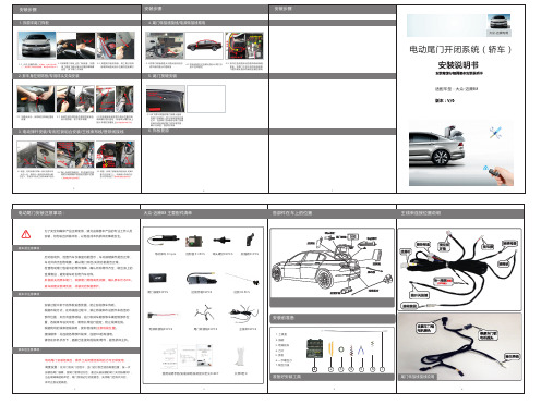
3.3 如图,将尾门按键线/转接线从支撑杆 管内引至尾门上,电源线从饰板内引 至中控驾驶位(搭铁线接线位置如图)
原车预留的尾 门按键槽位
5.1 拆下原车预留的尾门按键小盖板, 将尾门按键装入原车饰板预留的槽 位中,连接尾门按键线与尾门按键, 安装完成后测试尾门的各项功能, 确认无误后,复原各饰板
6. 饰板复原
安装前准备
根据我司的线束接线说明,接好各线束(注意地线位置)。 接线顺序:先连接各零部件线束,连接OK后再通电。 请勿在开机状态下,插拔已连接好的线束/附件,避免损坏主机。
装车后注意事项:
电动尾门安装结束后,需手工关闭激活系统后方可正常使用。 高度设置:在开门或关门过程中,当门运行到合适的高度位置,按一次 加装的尾门按键,使尾门暂停运行后,通过长按加装的尾门关闭按键3秒, 当出现嘀嘀的响声后,尾门系统记忆功能激活,关闭尾门后再次开启, 即可达到设定高度。
安装步骤
安装步骤
安装步骤
1. 拆原车尾门饰板
1.1 大众-迈腾外观(拆装前,先关闭原车尾 1.2 拆掉尾门饰板上的门锁胶套,如图 门,观察尾门两侧高低缝隙,确认原车状态OK) 用工具拆下箭头指示位置的两颗螺 丝后,拆下尾门大饰板
1.3 如图掰开锁扣饰板,用工具分别拆 除侧饰板箭头指示位置的固定螺钉
2. 拆车身左侧饰板/专用球头支架安装
加强板 球头螺钉
原车弹簧
用螺丝固定 用螺丝固定
原车球头
2.1 如箭头所示,拆掉锁扣饰板处固定 胶塞
2.2 拆掉左侧支撑杆处的塑胶固定板后 掰开侧饰板,取下原车弹簧
2.3 将加强板安装在图中指示位置并用 两颗螺钉进行固定,专用球头螺钉装上 垫片安装在加强板上(内侧的原车球头不拆)
3. 电动撑杆安装/专用拉锁组合安装/主线束布线/搭铁线接线
汽车加装电动尾门教学设计
汽车加装电动尾门教学设计一、介绍汽车加装电动尾门是一项常见的改装项目,它为车主提供了便捷的尾门打开方式。
传统的手动尾门需要通过人工推拉才能打开或关闭,而电动尾门则可以通过按键或遥控器实现自动开合。
在本文中,我们将讨论如何进行汽车加装电动尾门的教学设计。
二、教学目标1.了解电动尾门的基本工作原理;2.掌握电动尾门的安装步骤;3.了解电动尾门的注意事项和常见故障排除方法;4.能够独立完成汽车加装电动尾门的操作。
三、教学内容3.1 电动尾门的基本工作原理在开始进行汽车加装电动尾门之前,首先需要了解电动尾门的基本工作原理。
电动尾门通过电机驱动和控制系统控制尾门的开合,其中电机通过蜗杆和齿轮驱动尾门的运动。
控制系统通过信号输入和电路控制实现对尾门开合的操作。
3.2 电动尾门的安装步骤1.确认车辆适用性:首先需要确认车辆的适用性,不同型号的汽车可能有不同的电动尾门安装方式和适用性要求。
2.准备工具和材料:准备安装所需的工具和材料,包括螺丝刀、螺丝扳手、导线、电动尾门套件等。
3.拆卸原有尾门:使用螺丝刀和螺丝扳手拆卸原有尾门,注意安全操作,防止尾门损坏。
4.安装电动尾门套件:根据厂家提供的安装说明,安装电动尾门套件,包括安装电机、蜗杆、齿轮等。
5.连接电路:根据电路图和说明书,连接电动尾门系统的电路,确保信号传输和电源供应的正常工作。
6.测试和调整:完成安装后,进行电动尾门的测试和调整,确保尾门的打开和关闭操作正常。
3.3 电动尾门的注意事项和常见故障排除方法在汽车加装电动尾门的过程中,需要注意以下几点:1.严格按照厂家的安装说明进行操作;2.注意安装过程中的安全操作,避免人身伤害和车辆损坏;3.确保电路的连接正确,避免短路和火灾等安全问题;4.定期检查电动尾门的工作状态,及时发现并解决故障。
常见的电动尾门故障包括电机损坏、电路接触不良、遥控器失灵等,排除方法可以通过检查电路连线、更换电机、更换遥控器等方式解决,如果无法解决,建议联系相关专业人士进行检修或维修。
汽车尾板安装使用说明书
汽车液压升降尾板安装使用说明书★系列:DC-WB10、DC-WB15、DC-WB20、WB30DC-WBL10、DC-WBL15版权所有东莞市达成机械设备制造有限公司地址:广东省东莞市寮步镇小坑工业区电话:(余生)传真:8前言非常感谢您智选使用达成汽车液压升降尾板。
在使用该设备之前,我们诚恳地希望您能花点时间仔细阅读本说明书,以便能让达成尾板更好地为您服务。
达成尾板是根据欧美国家最先使用的悬臂类型运输装载工具,加上最先进的液压系统设计改进,成为国内新一代的随车运输装载设备。
由于它安装简单、操作方便、使用可靠,因此它能适合安装在各式货车和有主体的拖挂车上,满足不同行业领域的运输装卸要求。
达成尾板安装在货车的尾部,主要用来随车装卸货物。
另外还可以用作固定或活动平台,可作为调节货车与仓库货台之间高度差的辅桥。
根据车主的需要,且具备达成尾板也可直接用来代替车厢尾门密封车厢,有效防盗功能。
达成尾板是由形成平行线的封闭式油缸、支架、液压泵站、电气控制元件和面板等通过销轴连接组合而成。
呈平行四边形的支架横梁与汽车大梁固定安装,板面通过油缸上下平行移动,工作时面板总是处于水平状态,也可根据需要通过调整,实现向上或向下倾斜。
升降油缸和摆动油缸通过支架使尾板保持平衡。
在升降操作过程中,尾板成水平的程度或倾斜的位置由摆动油缸来调整。
升降油缸执行升或降的动作,摆动油缸执行倾斜的动作。
达成尾板油缸、支架的动作是通过液压动力箱中的组合阀和二位三通电磁换向阀来控制。
其启动电压为DC24V或DC12V。
液压动力箱主要由齿轮油泵、直流电机、启动装置、溢流单向电磁卸荷组合阀和二位三通电磁换向阀、油箱及滤油器等组成。
液压动力箱的电源由货车的蓄电池来提供。
当蓄电池能量不足时,就需要通过较长距离地行驶车辆或用充电器来充足电能。
电气控制箱由三个按钮和保险管、钥匙旋钮式电源总开关及箱体组成。
轻轻用力推入钥匙开关,顺时针旋转90度即接通电源,当尾板不工作时可将电源全部切断,逆时针旋转90度即可。
5系电动尾门施工方案
5系电动尾门施工方案一、施工准备确认施工所需的工具和材料已准备齐全,包括电动工具、切割工具、焊接设备、螺丝刀、线路板、撑杆、模块等。
确保施工现场安全,采取必要的防尘、防火措施,并准备好急救箱等应急设备。
仔细阅读施工图纸和技术要求,明确施工步骤和注意事项。
二、拆除门板盖使用螺丝刀和拆卸工具,按照图纸指示拆除尾门内饰板。
轻轻将门板盖取下,注意避免损坏周围的饰件和油漆。
三、切割按键位置使用切割工具在指定的位置切割按键孔,确保尺寸精确。
切割过程中注意保持手部稳定,避免产生毛刺或不平整的边缘。
四、更换撑杆使用螺丝刀和扳手拆下原有撑杆,注意记录接线位置和方式。
将新的撑杆按照接线图示接入相应线路,确保接触良好。
五、供电与接线根据图纸指示,确定电动尾门模块的供电线路和控制线路。
使用焊接设备或压接工具进行线路连接,确保连接牢固可靠。
六、安装模块将电动尾门模块安装在指定位置,确保固定牢固。
检查模块与线路的连接情况,确保无误。
七、调试与操作连接电源,启动电动尾门系统,检查各项功能是否正常。
进行多次开关尾门的操作,观察撑杆动作是否平稳,按键是否灵敏。
八、安装盖板将切割好的按键盖板安装回原位,确保安装牢固。
检查盖板与门板的贴合情况,确保无缝隙或错位。
施工完成后,再次检查电动尾门系统的功能,确保无误。
整理施工现场,清理残留物和垃圾,保持施工环境整洁。
注意:本施工方案仅供参考,具体施工过程中应根据实际情况进行调整。
施工前应确保了解相关安全规定,并采取必要的安全措施。
现代Casper电尾门安装说明
现代Casper电尾门安装说明
1、现代Casper电尾门安装说明先用小一字螺丝刀撬出卡扣放心撬,是铁的拆底座螺丝就可以拿下撑杆再拆掉上支座电尾门配套的支座。
要分清左右,以及安装方向。
有箭头标识,朝前一定要防水垫安装电尾门撑杆上下支座安装电动撑杆,要分清左右标识。
2、直接按压扣上就行。
另一边一样,在此不再重复从手指示的位置撬饰板,左右都可以。
要用塑料撬棒撬开,再用手稳住劲的拉下来,一定要平稳。
以防损坏饰板卡扣拿下第一块饰板,白色的就是卡扣,拆的时候找好发力点,一定要平稳用力,卡扣一个都不会坏。
拆掉两颗十字螺丝,手指的位置。
左右各一就可以拿下两边饰板拆掉螺丝拉手孔里的螺丝拆掉手指位置的螺丝,左右各一。
就可以拉下饰板。
找好受力点,平稳发力,咔咔的就拉下来了最后一块大饰板就可以拉下来了。
拆掉锁头换上电吸锁从橡胶管中穿线。
3、需要用到穿线器和表板蜡没有表板蜡,用的车蜡。
抹在电线上,穿起来很顺滑。
表板蜡就没有问题已经成功穿线我是从驾驶室开始布线,最后剩余线长都绑扎在尾门里面了。
4、撬开驾驶室的保险丝盒,最好用塑料撬棒。
从上撬开,沿边拉开。
一句话就是要平稳发力,卡扣就不会坏。
取出这个保险丝连接电尾门配套的取电器一根线保险盒插电,一根压在螺丝下面接地接好线试了一下,电尾门可以正常工作。
- 1、下载文档前请自行甄别文档内容的完整性,平台不提供额外的编辑、内容补充、找答案等附加服务。
- 2、"仅部分预览"的文档,不可在线预览部分如存在完整性等问题,可反馈申请退款(可完整预览的文档不适用该条件!)。
- 3、如文档侵犯您的权益,请联系客服反馈,我们会尽快为您处理(人工客服工作时间:9:00-18:30)。
资料内容仅供您学习参考,如有不当或者侵权,请联系改正或
者删除。
天鉴电动尾门
安装说明书(自由光)
资料内容仅供您学习参考,如有不当或者侵权,请联系改正或
者删除。
电动举升门安装
一、注意事项
●本说明书中的所有图片仅供参考, 图片与实物有可能不同, 但安装方法是一样的。
资料内容仅供您学习参考,如有不当或者侵权,请联系改正或二、配件
者删除。
资料内容仅供您学习参考,如有不当或者侵权,请联系改正或
者删除。
三、安装步骤
参考配件清单
和配件图检查
拿出备胎, 并
拆开后盖板
资料内容仅供您学习参考,如有不当或者侵权,请联系改正或
者删除。
拆开左边侧饰板。