东星智能流量控制器说明书
VMS-MC- -4G 多功能控制器用户手册说明书
VMS-MC-*-4G多功能控制器用户手册Ver2.0目录第1章产品简介 (3)1.1产品概述 (3)1.2功能特点 (3)1.3主要参数 (3)1.4产品选型 (4)第2章硬件连接 (4)2.1设备安装前检查 (4)2.2设备安装及维护 (5)2.2.1接线前后注意事项 (5)2.2.2接线说明 (5)2.3安装方式 (6)2.4设备安装注意事项 (6)2.5设备维护与保养 (6)2.6常见问题及解决方法 (6)第3章接入云平台 (7)3.1上传节点设置及说明 (7)3.2设置举例 (7)3.3继电器操作说明 (7)3.4手机APP控制继电器说明 (8)3.5本地端控制 (8)第1章产品简介1.1产品概述VMS-MC-*-4G多功能控制器是一款集成多路继电器的控制器。
本地端7寸触摸屏,多路开关量输出可用于各类场合的即时控制,可控制小于10A-250VAC/30VDC的设备,若控制大型设备,再连接中间继电器即可。
本产品即支持本地端手动控制,也可以充分利用已架设好的通讯网络连接至我司云平台,可通过电脑登陆云平台及手机APP实现远距离的继电器控制,实现各类设备的集中控制,可大大减少施工量,减少施工成本和维护成本。
同时多功能控制器采用壁挂安装,使用方便。
广泛应用于:家居智能开关控制、酒店智能开关、宾馆智能电器控制、商场智能开关、公司厂房智能开关、网吧定时管理、卡拉OK计时控制、物联网、工控设备、测试设备电源控制、路灯管理、智能管理,集中电源管理等。
1.2功能特点⏹7寸触摸屏,中文展示,界面操作简洁;⏹4G(全网通)数据上传,减少施工成本和维护成本;⏹断电后自动断开继电器;⏹支持设备端手动控制,同时支持平台手动,自动、定时等控制方式;⏹自动条件,可联动同平台所有采集类设备;⏹支持我司提供的多款免费软件平台、用户也可以自己开发平台;⏹交流220V供电、可常年工作于室外。
1.3主要参数供电电压220VAC,50HZ功耗20W通信方式4G通信工作环境工作温度:-10℃~﹢50℃工作环境湿度:10%RH~85%RH继电器带载能力30V/10A-DC、255V/10A-AC 设备尺寸360*300*125(单位:mm)整体尺寸:360*300*125(单位:毫米1.4产品选型VMS-公司代号MC-多功能控制器R08-8路无源继电器R16-16路无源继电器4G4G上传第2章硬件连接2.1设备安装前检查设备清单:⏹主设备1台;⏹合格证、保修卡等;⏹膨胀螺栓2个;⏹4G天线。
流量控制器 FC01

M_FC01_0108_e流量控制器FC01用户手册请认真遵守下列说明。
不遵守说明,或使用不当,可能对设备本身和安装设施造成严重损坏。
E-T-A 概不对客户或第三方承担责任,也不对由于未遵守这些说明造成安装不当或处理不当而引起的质保索赔或损坏负责。
该说明涵盖软件版本1.71。
设备安装、连接和调试只能由具备资格的专业人员进行!目录表1 描述 (1)1.1 测量程序 (2)1.1.1 量热测量程序 (2)1.1.2 机械程序 (3)1.2 系统描述 (4)1.2.1 用户界面 (5)2 安装 (7)2.1 量热监测探头的安装 (7)2.1.1 材料选择 (7)不锈钢1.4571 / AISI 316 Ti (7)镍基合金(哈式合金2.4610) (7)2.1.2 机械安装 (8)2.1.2.1 螺纹安装式监测探头CST-01 (8)2.1.2.2 监测探头CST-01 带可调浸入深度 (9)2.1.2.3 法兰安装式监测探头CSF-02 (10)2.1.2.4 卫生探头CSF-03(三夹钳式) (11)2.1.3 监测探头CST 安装说明 (12)2.1.3.1 液体介质 (12)2.1.3.2 气体 (13)2.1.3.3 密封 (14)2.1.4 监测探头CST 01 安装说明 (14)2.1.4.1 安装区和稳定区要点 (14)2.1.5 电气连接 (16)2.2 涡轮式传感器安装 (17)2.2.1 机械安装 (17)2.2.1.1 监测探头TST..AM1/WM1 (17)2.2.1.2 监测探头TST..HM2 (18)2.2.2 安装说明 (19)2.2.2.1 管道内安装 (19)2.2.3 电气连接 (20)2.3 电气控制单元FC01 的安装 (21)2.3.1 机械安装 (21)2.3.1.1 导轨安装式版本FC01-U1... .. (21)2.3.1.2 表面安装式版本FC01-FH-U1... .. (22)2.3.1.3 前面板安装式版本FC01-ST-U1... . (23)目录表I2.3.2 电气连接 (24)2.3.2.1 电路图FC01 24 V(继电器输出) (27)2.3.2.2 电路图FC01 24 V(晶体管输出) (28)2.3.2.3 电气连接–频率输出(版本FC01-U1T4) (29)3 操作系统 (31)键盘(M) 模式、(▲) 向上和(▼) 向下 (31)菜单翻页 (32)调出菜单选项 (32)输入数字 (32)转移输入 (32)删除数据 (32)4 操作和主菜单 (33)4.1 开关性能 (33)4.2 测量周期 (33)4.2.1 操作数据 (34)4.2.1.1 测量值 (34)4.2.1.1.1 量热监测探头CSx (35)4.2.1.1.2 涡轮式传感器TST (36)4.2.1.2 峰值(最小峰值/ 最大峰值) (37)4.2.1.3 上次误差 (37)4.2.1.4 主菜单 (38)5 配置 (39)5.1 监测探头选择 (39)5.2 监测探头数据 (40)5.3 介质选择 (40)5.4 限位开关组合 (41)5.5 流量单位 (41)5.6 介质温度单位 (42)5.7 显示器 (42)5.8 条形图 (43)5.9 管道直径 (44)5.10 频率输出 (44)5.11 模拟输出–流量 (45)5.12 模拟输出–介质温度 (45)5.13 退出配置菜单 (45)II 目录表5.14 配置菜单 (47)5.15 配置子菜单 (48)5.16 测量范围和菜单可及性 (51)6 参数选择 (52)6.1 测量时间 (52)6.2 限位开关1 开启/关闭值 (52)6.3 限位开关2 开启/关闭值 (53)6.4 定标因数 (54)6.5 退出参数选择菜单 (54)6.6 参数选择菜单 (55)7 误差 (56)7.1 测试和诊断 (56)7.1.1 优先组I (56)7.1.2 优先组II (56)7.1.3 优先组III (56)7.2 潜在误差 (57)8 技术数据 (59)8.1 环境条件 (59)8.2 电气特征 (59)8.2.1 电源供应 (59)8.2.1.1 直流供压 (59)8.2.1.2 交流供压 (60)8.3 模拟输出 (60)8.3.1 电压输出V1 - 5 V FS (61)8.3.2 电压输出V2 - 10 V FS (61)8.3.3 电流输出C1 - 20 mA FS (61)8.4 信号输出 (62)8.4.1 继电器输出R2 (DC 或AC) (62)8.4.2 晶体管输出(DC) (63)8.5 计量数据 (64)8.5.1 带量热监测探头的FC01 (64)8.5.2 用于FC01 / 选择器图表的量热监测探头 (65)8.5.3 带涡轮式传感器的FC01 (66)8.5.4 用于FC01 / 选择器图表的涡轮式传感器 (66)8.5.5 电气控制单元FC 01 (66)目录表III8.6 传感器接口 (67)8.6.1 量热监测探头接线端电气数据 (67)8.6.2 涡轮式传感器接线端电气数据 (68)9 附件 (68)索引附录1 操作和误差模式下数字及模拟输出的性能2 FC01 菜单结构(操作员对话框)IV 目录表1 描述流量控制器FC01 设计目的在于检测流量速度、流量体积以及介质温度,若使用了量热型监测探头(型号CSx)。
First Sensor FMA5400 5500电子气体流量控制器说明书

D-27SPECIFICATIONS Accuracy: ±1.5% FS, including linearity over 15 to 25°C (59 to 77°F)and 0.7 to 4.2 kg/cm 2 (10 to 60 psia) ±3% FS for units ≥100 SLM from 0 to 20% of rangeRepeatability: ±0.5% of full scaleTemperature Coefficient: 0.15% FS/°C Pressure Coefficient: 0.01% FS per psi (0.07 bar)Maximum Pressure Drop: 50 psid Response Time: 5 seconds to within ±2% of set flow rate over 25 to 100% FSThe FMA5400/5500 Series electronic gas mass flow controllers can control the flow of a wide variety of gases from 10 SCCM up to 1000 SLM. Utilizing heat transfer through a heated tube, the FMA5400/5500 measures gas mass flow rate directly, without needing to compensate for variations in gas temperature or pressure (within stated limits). They are available in an economical aluminum/brass construction for typical gas flows and a 316 SS construction for applications that require more corrosion resistance. The FMA5400 Series without integral display is supplied with both an analog 0 to 5 Vdc and 4 to 20 mA output for remote monitoring; the FMA5500 Series features an integral 3¹⁄₂ digit display and an analog output. The display is tiltable over 90 degrees for viewing convenience and is calibrated to read out directly in SCCM or SLM for nitrogen (other gas calibrationsavailable by special order).The FMA5400/5500 mass flowcontrollers feature a built-inelectromagnetic valve for maintaining a constant flow rate regardless of variations in inlet or outlet pressures. The setpoint is controlled either locally via a potentiometeraccessible through a window in the case or remotely via an analog 0 to 5 Vdc or 4 to 20 mA signal (field selectable).The FMA5400/5500 Series controllers require 12 to 15 Vdc power @ 800 mA maximum, which can be supplied by the FMA545PW wall plug-in socket power supply (24 Vdc power input @ 650 mA is available as an option). The electronics are reverse-polarity protected and have a resettable fuse. Model number FMA545C (supplied separately) provides a mating 15-pin “D” connector with 2.4 m (8') of shielded cable for accessing the analog output signals and power input connections. The LCD for the FMA5500 Series is connected to the lower electronics via a modular plug. The LCD can be remotely located by purchasing an FMA18RC remote cable assembly–you must then build your own assembly for panel mounting the LCD.Economical Gas mass Flow conTRollERsFor clean Gaseswith optional integral DisplayMaximum Gas Pressure: 35 kg/cm 2 gage (500 psig); 1.76 kg/cm (25 psig) optimumGas and Ambient Temperature: 5 to 50°C (41 to 122°F)Leak Integrity: 1 x 10⁻⁷ cc/sec of helium max to outside environment Materials in Fluid Contact: Aluminum Models:Anodized aluminum, 316 SS, brass and FKM O-rings Stainless Steel Models: 316 SS and FKM O-rings Output Signal:Linear 0 to 5 Vdc: 1000 V minimum load4 to 20 mA: 50 to 500 V loop resistance, ±20 mV max noiseTransducer Power: 12 Vdc @ 800 mA standard; 24 Vdc @ 650 mA optional Turndown Ratio: 50:1Shipping Weight: 1.8 kg (4 lb)Compliance: EN55011 class 1, class B; EN50082-1Altitude Sensitivity: With horizontal flow path, no shift in calibration up to +20 degree pitchGas Relative Humidity: 0 to 70% RHFMA5402ST mass flow controller without display, 316 SS body, shown smaller than actual size.FMA5512, shownsmaller than actual size.U NIST-Traceable CalibrationU Reads and Controls Gas Mass Flow Without Temperature or Pressure CompensationU Available in Economical Aluminum orCorrosion-Resistant 316 SSU Tiltable LCD for Easy ReadingFMA5400 SeriesD-28D* Comes with 3⁄4 FNPT connections instead of compression fittings.Comes complete with compression fittings, NIST certificate and operator’s manual. Power supplies sold separately.Flow ranges specified are for nitrogen or air at 20 psig inlet (up to 50 SLM) or 25 psig inlet 60 to 100 SLM units) and 0 psig outlet. When used with other gases, a multiplication factor is used to determine the flow rate, and the digital display must be rescaled in the field.To request a custom calibration add the gas abbreviation and inlet pressure/outlet pressure as a suffix to the model number.Calibration are done at ambient temperatures only, 20ºC (70ºF)For 24 Vdc powered units, add suffix “-24VDC” to the model number, no additional cost.For oxygen cleaned units, add suffix “02CLEAN” to model number for additional cost.Ordering Examples: FMA5410–ARGON , 50/0 psig, 70°F calls for an AL/BR body flow controller without an integral display, calibrated for Argon at 50 psig inlet pressure, 0 psig outlet pressure, 70°F gas temperature, powered by 12 Vdc.FMA5516, N 2 controller with display, and FMA545PW , power supply.FMA5512, shown smallerthan actual size.。
流量控制器SG4300简要使用说明
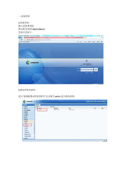
一,设备管理
1,设备登录:
输入设备IP地址
默认账号/密码:Admin/Admin
登录方式如下:
2,修改管理员密码:
进入”系统配置->管理员账号”,点击账号admin进入修改密码:
二,流控管理
以配置10M线路的流控为例:
要求限制P2P,P2P下载,网络流媒体,下载工具等非关键应用带宽,保障WEB应用,游戏,邮件,办公OA等关键应用带宽,实现步骤如下:
1,配置虚拟线路:
进入”流量管理->虚拟线路配置”,点击”线路1”编辑速度1.25MB/S,即总带宽为10MB:
2,配置各种应用的带宽:
进入”流量管理->通道配置”,点击”新增通道”,添加对各种应用带宽的分配: (1)新增”WEB等关键应用等”,分配策略如下:
点击”带宽通道设置”,给通道分配带宽:
点击”通道使用范围”,选择使用该通道的对象,应用,通道生效时间等:
(2)新增” P2P与下载工具等应用限制”, 分配策略如下:
点击”带宽通道设置”,给通道分配带宽:
点击”通道使用范围”,选择使用该通道的对象,应用,通道生效时间等:
三,上网审计
需求:实现对普通用户上网行为的记录,保证公安机关查询,实现步骤如下: 1,进入”用户与策略管理->上网策略”,点击”新增”并选择”上网审计策略”:
2,添加审计策略名为”普通用户上网行为记录”:
3,添加要审计的行为内容:
4,点击”适用组和用户”,选择需要做审计的对象:
点击提交后,最终设置结果:
5,查看用户上网记录:
(1)进入”实时状态->上网行为监控”,实时查看用户上网行为:
(2)点击页面右上角”内置数据中心”查看用户上网历史记录:。
IC卡智能燃气流量控制器说.pdf

真诚的感谢你选用我公司的IC卡智能燃气流量控制器,为了你能够正确地使用该产品,本说明书对产品的安装、操作和维护等做了详尽的说明。
因此请你在使用前一定要仔细阅读本说明书。
谢谢!IC卡智能燃气流量控制器说明书K型为窄屏版,B/C宽屏版衡水多元仪表有限公司关于本套用户说明书该说明书必须提供给控制器使用方该说明书必须妥善保存直至控制器不再使用未经预先通知,本套说明书的内容有可能改动版权所有,未经本公司书面同意,不得以任何形式复制说明书的任何内容。
本公司不对说明书做任何形式的保证,其中包括但不限于本说明书的出售及用于其他目的本公司努力确保说明书各项内容的正确性,但若发现任何错误或者疏漏,请通知本公司。
除上面提到的内容以外,本公司不对本产品承担任何其他责任如产品规格、结构或着操作的改变不影响其运行、使用和性能,用户说明书不随之修订。
使用注意事项1.1使用前控制器选型1.1.1控制器一般操作压力不允许超过4公斤,请选型前必须注意安装位置的操作压力不得大于4公斤。
1.1.2控制器需要流量计有脉冲当量输出到控制器,远传型的需要流量计有RS485通讯接口,通讯协议必须进行过互相通讯。
具体参数详见技术参数1.2确认收货1.2.1在您拿到本产品时请确认运输中有无磕碰划伤等1.2.2根据产品铭牌、合格证请确认与您要买的型号及技术参数是否相符1.3运输与储存1.3.1尽可能利用原厂包装将控制器直接运送到安装现场1.3.2运输过程中避免潮湿淋浴、避免阳光直接暴晒、避免强烈触碰、震动1.3.3尽量利用原厂包装进行保管并符合下列条件要求:不要放在淋雨或潮湿的地方震动或碰撞不到的地方温度:-20℃---+55℃湿度:5%----80%1.3.4使用过的控制器保管时需要对控制器内部和表面进行清理干净,不要缺少零部件。
1.4安装1.4.1使用时要在控制器规定的环境条件和技术条件下使用,超出这个规定使用是不行的。
如果因此而造成控制器损坏等现象,后果及维修费用均会有您自己承担。
MC-700系列质量流量控制器使用说明书

LN0427E2103E0Mass Flow Controller Instruction ManualSafety PrecautionsIncorrect handling may cause death or injury(1)Before connecting the fittings, check that no damage or defects are found on the fittings. Make connections properly and make sure that a leak test is conducted before actual operation to prevent fluid from leaking into the atmosphere (Hereafter, the measured fluid is called “gas” or “fluid”).(2) DO NOT apply any fluids corrosive to materials exposed to gas. Corrosion may cause fluid to leak into the atmosphere. Check the gas type to be used in advance. (3)This device is not designed as an explosion proof structure. DO NOT use this device in a place where explosion-proof structures are required. Doing so may cause fire or explosion.Incorrect handling may lead to medium or slight injury or may cause damage to, or loss of, facilities or equipment(1) Observe the precautions listed in the WARNING (above)(2) Strictly observe the electrical specifications. Not doing so may cause fire, damage to sensors or malfunction.(3) This device is not designed to be waterproof. DO NOT locate this device outdoors or in a place where it may be splashed with water. Doing so may cause fire, trouble, or malfunction of the device.(4) DO NOT modify this device. It may cause fire or other problems.(5)This device is not designed to handle hot swap. Please avoid attaching and removing the power supply connector and interface connector with the power switched on. Attachment and/or removal with the power on may result in failure of the device.(6) While a power supply is applied to MFC, ±15VDC must be applied simultaneously. If only +15VDC or -15VDC is applied, electronic circuits will become unstable and it may cause a malfunction of MFC.(7) This device is a precious device, please handle it carefully. Dropping down or handling it carelessly will cause damage. Please use assist instrument while moving or setting the device.(8)Regular maintenance is recommended for steady use of this device (Recommended proofreading frequency is once a year).1. IntroductionThis manual explains basic operation of the MC-700 series (Hereafter, it is called"MFC"). Please read through this manual and other separate volumes (Digital Interface Manual, Special Function Manual, Command Chart) carefully to familiarize yourself with the features of this device.2. SummaryThis device is the mass flow controller with the function of switching differentkinds of gas and flow rate (Hereafter called "variable function" or "VR"). By using the 3 rotary switches on the MFC, the gas type and flow rate can be changed. The rotary switches are placed conveniently on top of the MFC unit so thatadjustments can be made accordingly even after the unit is set in position. For old models, stocking MFC for each of gas and flowrate was necessary because only one spec is available to one MFC, and MC-700 can reduce your stocking because it can be used for more than one spec with one MFC.3. FeaturesThe MFC has the following features.(1) LINTEC’s proprietary ambient temperature compensation type flow sensor.·The influence of ambient temperature is small due to the sensor temperature control following the ambient temperature.·Since the temperature distribution of the sensor is constant, high-speed response is possible.(2) Gas type and flow rate setting can be changed by using the 3 switches on the mass flow controller unit.(3) Digital interface (RS-485) is standard equipment and the maximum of 32 MFCs could be connected together with daisy chain. (Option: Digital interface RS-232C is possible)(4) Small structure of dead volume using diaphragm valve.(5) Stainless steel 316L is used because of good corrosion resistance and seal ability. (6) Particule-free structure(7) RoHS compliant, CE conformity4. StructureThe MFC consists of sensors, bypass, valves, and a microcomputer for signalprocessing. A digital PID feedback control system controls the valve action so that flow rate output from the sensor agrees with flow rate setting value.5. Specification / DimensionsNote 2) The value at the time of shipping. This may change with gas type and flow rate setting. · Connect the MFC to the ground.(2) Dimensions6. Ordering informationMC-710 MC - 4VR2 A0A0A0 - 06 - N2 - 1.5SLM [1] [2] [3] [4] [5] [6] [7][1] Model: MC: Mass Flow Controller Series MC-710 MC-720 MC-730 [2] Valve operation mode · Internal surface treatmentNO: Normally opened valve / No treatment NC: Normally closed valve / No treatmentMO: Normally opened valve / Precision polishing MC: Normally closed valve / Precision polishing [3] Fitting4VR2: 6.35VCRType 124mm4VR1: 6.35VCRType 106mm (option) 4SWL: 6.35SWLType 127mm (option) ※ Please consult us for other fitting types. [4] Other optionsDefault settings is labeled “A 0A0A0”, please consult for more information. [5] VR Number [6] Gas type[7] Full scale flow rate and unit: SCCM(0°C standard), SLM(0°C standard)7. Connection(1) Analog interface connectorMounted connector : D-Sub 9 pin(male)Note4)Pin No.[4],[7]and No.[8] are connected internally in MFC.Wirings should be done as shown below in order to remove the effect of potential difference among the COMMON.Do not connect. Flow rate setting signal COMMON[8], Flow rate output signal[7], and Power supply COMMON[4] in the power supply unit.(2) Digital interface connectorMounted connector : RJ-45 Modular jack Pair connector : RJ-45 Modular plugR0 or R1. Refer to the attached sheet of digital interface instruction manual for connection. Note6)[Power OUT] means the power output of RS-1 interface and it is not applicable for connections to other machines without R1 option.· RS-1 is a discontinued product. Therefore, MC-3000E series / MC-2000 series can be replaced with MC-700 series including option.8. Alarm functionsThe MFC has two types of alarm functions built in. In addition, alarm status can be confirmed using both digital communication (alarm output from the digital connector) and an LED located on top of the body of the MFC. As alarm settings can only be changed using digital communication, please carry out necessary changes using this method. For 9. Software switch (factory shipped value)This MFC is provided with a software switch for operation mode setting. Beforeoperation, input the necessary data for various functions by using the digital interface.· If the zero adjust button on the top of the MFC is pressed and held for over 5 seconds, the communication protocol is reset to default.10. Operation (1) Procedure1)This product is packed in a clean room before shipment. Please break theseals in a clean room after taking it out of its box.2) Check the gas type and flow rate and check the direction of the gas flow and the MFC before installation.3) Check for gas leaks from the tubing with a helium (He) leak detector. 4) Connect the interface connectors according to the Connector table.5) Power requirements are +15VDC:120mA and -15VDC: 50mA. Check the voltage, polarity, and capacitance of the power supply voltage.6) Turn on power supply and let the equipment warm up for at least 5 minutes (Recommended time: 30min).7)Adjust the zero point by pressing the zero adjustment, switch located on the top of the MFC. Before zero-point adjustment, check that gas is not being supplied and the device was warmed up for 30 minutes or more in order to ensure sensor stability.8)Input the flow rate setting signal and supply gas with required differential pressure to the MFC. The MFC will begin to control the gas flow in proportion to the preset voltage. Full-scale voltage is 5VDC. Maximum input voltage is ±15.5VDC.9) When the output flow rate signal is used, the tolerance voltage of the external device should be more than ±15.5VDC. When it’s conne cted the output valve may be within the range of the maximum voltage ±15.5VDC. 10) Complete shut-off cannot be achieved with the mass flow controller. If complete shut-off is desired, a shut-off valve should be installed.11) When a highly reactive gas is used, thoroughly purge all foreign matter from the tubing and the MFC before operation.12) When contaminated gas is used, install a filter at the equipment inlet.13)Use the MFC within the range of the operating temperature (15 to 35°C), and keep it at the same temperature with the gas. If used in any environment that does not meet the above-mentioned requirements, the flow rate cannot be measured accurately and the device may fail.14)Do not switch the power supply on and off within one second. It may cause failure.(2) Valve control signalThe MFC features a forced valve open/close input function.The connector pin No.1 is used to input the internal valve open/close signal. By inputting this signal, a forced opening/closing of the internal valve can be performed without depending on the value of the flow rate preset signal. When +15VDC is input: fully open When –15VDC is input: fully closed(3) Variable Range functionBy using one device of MFC, it is possible to modify multiple flow rate ranges and gas types. To modify the flow rate or the gas type, refer to the following VR corresponding chart or the calculation formula, and modify the variable range by the rotary switches (for analog control) or digital communications (for digitalcontrol).[Formula](standard flow rate) ÷ (desired flow rate) × (conversion factor) By using this function, the flow rate and gas type may be changed, however if a different gas is to be used, please consider the properties of the gas and confirm the responsiveness before usage. Also, in the case that the gas may cause debris or particle, please refrain from using it. If you have any questions of conversion factor, please contact us.(4) Digital interfaceThe MFC features the RS-485 or RS-232C (Note 5) digital interfaces. Manyspecial functions can be employed using the digital interfaces.Please refer to other manuals (Digital Interface Manual, Special FunctionManual Command Chart).11. Product warranty(1) PeriodThis product is guaranteed for a period of 1 year from date of shipment. Defects are repaired according to the following regulations.(2) ScopeWarranty coverage is restricted to this product only. Any other damage caused by an is not covered.(3) Disclaimer factsThe following repairs are not covered by the warranty:1) Failure caused by by-product of fluid used2) Failure caused by misuse (including careless operation) or incorrect repair ormodification3) Failure caused by dropping after purchasing4) Failure caused by a natural disastersEven if the warranty period is still in effect, the following items may not be repaired.1) In case of the product is returned with fluid remaining inside2) In case of what kind of fluid was not informed used on the productThe MFC is a precision instrument. Control may become unstable if electric noise, temperature change of fluid, pulsation of fluid pressure etc. occurs. Please be forewarned.This instruction manual is subject to revision without noticehttp://www.lintec-mfc.co.jpCorporate Headquarters4-1-23 Sekinotsu, Otsu City, Shiga Pref. 520-2277, JapanTEL.+81-(0)77-536-2210 FAX. +81-(0)77-536-2215Tokyo Branch Office3F Hattori Build., 4-30-14 Yotsuya Shinjyuku-ku Tokyo 160-0004, JapanTEL. +81-(0)3-5366-2801 FAX. +81-(0)3-3341-3513。
自动流量调节器127系列说明书
replaces 01166/09 GBCompact automatic flow rate regulator with polymer cartridgeFunctionAUTOFLOW ® devices are automatic flow rate regulators capable of keeping the medium flow rate constant as the operating conditions of the hydraulic circuit change. They are used to automatically balance the hydraulic circuit, guaranteeing the design flow rate to each terminal.This series of devices is fitted with a replaceable regulating element, made of high-resistance, scale-resistant and low-noise polymer, for specific use in the circuits of heating and cooling systems and domestic water systems.This particular AUTOFLOW ® series is also supplied with a compact, small valve body for easy installation on individual terminals or in areas of the system.PATENT.Product range127 series Compact automatic flow rate regulator with polymer cartridgesizes 1/2", 3/4”, 1”, 1 1/4", 1 1/2” and 2”Technical specifications Materials Body:brass EN 12164 CW614NAUTOFLOW ® cartridge: - 1/2”–1 1/4”: high-resistance polymer - 1 1/2”–2”: high-resistance polymer and stainless steelSpring:stainless steelSeals:EPDMPerformance Medium:water, glycol solutionsMax. percentage of glycol: 50 %Maximum working pressure: 16 bar Working temperature range: 0–100 °C Δp range: 0,02–0,06 m 3/h: 20–200 kPa 0,085–11 m 3/h: 15–200 kPa Flow rates:0,02–11 m 3/hAccuracy: 0,02–0,06 m 3/h: ±15 % 0,085–11 m 3/h:±10 %Connections:1/2"–2" FDimensionsCircuit balanced with AUTOFLOW ®AUTOFLOW ® devices balance the hydraulic circuit automatically, ensuring that each terminal receives the design flow rate.Even when the regulating valves close the circuit partially, the flow rates in the open circuits remain constant at the nominal value .The system always guarantees the greatest comfort and the highest energy savings.Modern heating and cooling systems have to guarantee a high level of thermal comfort with a low consumption of energy. This means supplying the system terminals with the correct design flow rates, to produce balanced hydraulic circuits.Circuits balanced with manual valvesTraditionally, hydrauliccircuits are balanced using manual setting valves.With these static devices, such circuits are difficult to balance perfectly and have operating limitations when the regulating valves are partially closed. The flow rate in the open circuits does not remain constant at the nominal value .Unbalanced circuitsn unbalanced circuits, the hydraulic imbalance between terminals creates areas with non-uniform temperatures, resulting in problems with thermal comfort and higher energy consumption.Circuit balanci ngFunctionThe AUTOFLOW® device must guarantee a constant flow rate when the upstream/downstream differential pressure varies.t is therefore necessary to refer to the Δp - flow rate diagram and a basic diagram illustrating the operating modes and effects of the relevant variables.Operating principleThe regulating element of these devices consists of a cylinder and a piston which has dedicated lateral openings with fixed and variable geometry through which the medium flows. These openings are governed by the piston movement, on which the pressure of the medium acts. A specially calibrated spring counteracts this movement.AUTOFLOW® devices are high-performance automatic regulators. They regulate the chosen flow rates within very tight tolerances (approximately 10 %) and offer an unusually wide working range.Below the working rangeAUTOFLOW® devices7654321∆p absorbedby AUTOFLOW at 100 % load®extra ∆p absorbedby AUTOFLOW® at 50 % loadminimum ∆p required by AUTOFLOW Pump H∆p along the circuit (flow + return)AUTOFLOW ®Regulating valveDifferential pressures (∆p)CodeMinimum workingΔp (kPa)Δp range (kPa)Flow rates (m 3/h)127141 l l l 1515–200 (20–200*)0,02*; 0,04*; 0,06*; 0,085; 0,12; 0,15; 0,2; 0,25; 0,3; 0,35; 0,4; 0,5; 0,6; 0,7; 0,8; 0,9; 1,0; 1,2; 1,4127151 l l l 1515–200 (20–200*)0,02*; 0,04*; 0,06*; 0,085; 0,12; 0,15; 0,2; 0,25; 0,3; 0,35; 0,4; 0,5; 0,6; 0,7; 0,8; 0,9; 1,0; 1,2; 1,4; 1,6127161 l l l 1515-2000,5; 0,6; 0,7; 0,8; 0,9; 1,0; 1,2; 1,4; 1,6; 1,8; 2,0; 2,25; 2,5; 2,75; 3,0; 3,25; 3,5; 3,75; 4,0; 4,25; 4,5; 4,75; 5,0127171 l l l 1515-2000,5; 0,6; 0,7; 0,8; 0,9; 1,0; 1,2; 1,4; 1,6; 1,8; 2,0; 2,25; 2,5; 2,75; 3,0; 3,25; 3,5; 3,75; 4,0; 4,25; 4,5; 4,75; 5,0127181 l l l 1515-2004,5; 4,75; 5,0; 5,5; 6,0; 6,5; 7,0; 7,5; 8,0; 8,5; 9,0; 9,5; 10,0; 11,0127191 l l l 1515-2004,5; 4,75; 5,0; 5,5; 6,0; 6,5; 7,0; 7,5; 8,0; 8,5; 9,0; 9,5; 10,0; 11,0it with AUTOFL OW ®For proper identification of the device, fill in the chart indicating: the size, the flow rate and the ∆p range.Full codeSERIES DIAMETER5ªSERIESSIZEFLOW RATE AND RANGE ∆pThe fifth digit indicates the size:The fth digit indicates the size:The last three digits indicate the available ow rate valuesFLOW RATE AND ∆p RANGE7th 8th 9thMethod of cod ing for AUTOF LOW ® 127 seriesSPECIFICATION SUMMARY127 seriesAUTOFLOW ® compact automatic flow rate regulator. Connections 1/2” (from 1/2” to 2”) F x F . Brass body. High-resistance polymer cartridge (1 1/2” and 2” high-resistance polymer and stainless steel). Stainless steel spring. EPDM seals. Medium water and glycol solutions. Max. percentage of glycol 50 %. Maximum working pressure 16 bar. Working temperature range 0–100 °C. Δp range 15–200 (20–200) kPa. Range of available flow rates: 0,085–11 (0,02–0,06) m 3/h. Accuracy ±10–15 %. PATENT.Caleffi S.p.A.S.R. 229 n. 25 · 28010 Fontaneto d’Agogna (NO) · Italy Tel. +39 0322 8491 · Fax +39 0322 863723***************·© Copyright 2022 CaleffiWe reserve the right to make changes and improvements to our products and the related technical data in this publication, at any time and without prior notice.The website always has the most up-to-date version of the document, which should be used for technical verifications.。
智能流量板使用说明
智能流量板使用说明面板显示布置图一、按键说明:SET:设定键,按此键设定参数保存并进入下个菜单。
在正常显示状态下按下此键保持5秒进入设置状态。
SHT:移位键。
按下此键,设置位移动。
INC:置数键,按下此键,设置位数字加1。
SHT+INC:同时按下SHT和INC键退出设置状态。
参数设置步骤:第一步:按下SET键保持5秒进入设置状态:数字闪烁按SHT键:闪烁位移动,按INC键:数字加1。
第二步:输入正确的密码值后,按下SET键后松开进入下一状态:注:密码不正确时,查看菜单数据,数据不能修改。
数字不闪烁按SHT键:参数后退;按SET键:参数前进。
按INC键:数字闪烁按SHT键:闪烁位移动;按INC键:数字加1。
第三步:输入设定的数值后,按下SET键后松开数据暂存。
重复第二步操作方法修改完其他参数后,继续按SET键出现如下提示符:(询问参数是否永久保存?)数字闪烁按SHT键:参数后退;按INC键:选择yes(是)或者no(否)后按SET键保存所有参数。
第四步:同时按下SHT键和INC键后松开,退出设置状态。
***小数点移动操作方法:个别参数小数位可以移动。
当参数数字闪烁时(闪烁频率为1Hz),按SHT键使闪烁位移动;当小数点出现闪烁时(闪烁频率为1Hz),按INC键小数点移位。
不同的参数,小数点移动的位数也不同,可移动的最大位数已由程序员固定。
当小数点不能闪烁时,表示该参数小数位不能改变。
二;菜单详细说明(一)A菜单:用户菜单。
功能:基本参数设置。
密码可设定,出厂时的密码为159。
在流量显示状态下,按下SET键不松开保持5秒后,出现提示符“PASS”后,按SHT键或INC键修改数值为159,然后按SET键进入A菜单。
****任何时候同时按下SHT键和INC键退回流量显示状态。
(二)B菜单:用户菜单。
功能:流量参数设置。
密码可设定,出厂时的密码为2221。
在流量显示状态下,按下SET键不松开保持5秒后,出现提示符“PASS”后,按SHT键或INC键修改数值为2221,然后按SET键进入B菜单。
智能流量频率变送仪表使用说明书
智能流量频率变送仪表使用说明书一、概述●适用范围本系列智能数字显示流量频率仪表是智能型、高精度的数显流量频率控制测量仪表,与涡街、涡轮、电磁流量计频率传感器及变送器配接可构成各种量程和规格的流量频率测控系统。
(可以测量电压、电流、转速、频率等各种参数,可与PLC变频器配接构成各种测量系统。
可以带峰值,谷值。
订货请来电说明。
)二、主要技术指标基本误差:0.2%FS,14位A/D转换器(最大18位A/D转换器,订货时注明)。
输入信号:·NPN、PNP、开关量·电流: 0~10mA、4~20mA等(输入阻抗≤250Ω)·电压: 0~5V、1V~5V、mV等(输入阻抗≥1MΩ)采样周期:0.2S(10~200次/秒,用户可选)显示:双排4位LED数码管显示。
报警输出:仪表可带多个继电器输出,继电器触点容量 AC220V/5A或AC220V/1A。
最多可带16个继电器,可选择上限、下限控制,控制设定值和回差值全量程内自由设定变送输出:4~20mA、0~10/20mA(负载电阻≤250Ω,负载过大需注明)1~5V、0~5V、0~10V(负载电阻≥200KΩ)。
采用12位数字D/A芯片,隔离输出。
通讯输出:隔离通讯接口RS485/RS232 波特率1200~9600bps馈电输出:DC24V/30mA、DC12V/30mA温度补偿:0~50冷端温度自动补偿,误差:±1℃电源:开关电源 85~265VAC或DC24V或DC12V功耗:4W环境温度:(-20~70)℃(常温下开机运行30分钟后,可逐渐承受极限温度)(0~50)℃ (热电偶信号输入)相对湿度:≤85% 无凝露避免在带有腐蚀性和易燃易爆气体中使用面板尺寸: 160mm×80mm、96mm×96mm、96mm×48mm、72mm×72mm、48mm×48mm(本公司仪表自行研发生产,种类多,功能全,如用户可选快速采样,最快可以500次/秒,高精度18位A/D 采集,高精度16位D/A输出,输入信号20段曲线修正,满5位显示或6位显示,液晶显示,特殊的输入信号,多个继电器报警蜂鸣器输出,大功率的馈电输出等,订货时注明)三、端子接线⑴C规格96×48×100尺寸的仪表四、操作说明(一)按键功能■—在设定状态时,用于切换显示参数提示符和相应的设定值。
FMA-LP2600A系列流量控制器产品说明书
The FMA-LP2600A Series mass flow controllers use the principle of differential pressure within a laminar flow field to determine and control mass flow rate. A laminar flow element (LFE) inside the meter forces the gas into laminar (streamlined) flow. Inside this region, the Poiseuille equation dictates that the volumetric flow rate be linearly related to the pressure drop. A differential pressure sensor is used to measure the pressure drop along a fixed distance of the LFE. This, along with the viscosity of the gas, is used to accurately determine the volumetric flow rate. Separate absolute temperature and pressure sensors are incorporated and correct the volumetric flow rate to a set of standard conditions. This standardized flow rate is commonly called the mass flow rate and is reported in units such as standard cubic centimeters per minute (SCCM) or standard liters per minute (SLM).The controller uses a true proportional valve coupled to the flow body to control flow using the integral PID loop controller. Standard units include a 0 to 5V output (4 to 20 mA optional) and RS232 communications. The gas-select feature and the setpoints can be adjusted from the front keypad or via RS232 communications. Volumetric flow, mass flow, absolute pressure, and temperature can all be viewed or recorded through the RS232 connection. It is also possible to multi-drop up to 26 units on the same serial connection to a distance of 46 m (150').U 130+ Gas Calibrations Including Pure and Mixed GasesU P ressure, Temperature, and Mass Flow Simultaneously DisplayedU Easy-to-Use Pushbutton InterfaceU NIST Traceability StandardU F ull Scale Ranges from 0.5 SCCM to 500 SLMU Response Time of 50 to 100 ms TypicalU Turndown Ratio of 200:1U Position InsensitiveU ±0.8% Reading AccuracyU RS232 StandardU Custom Live Gas Blend ProgrammingU Store Up to 20 User Defined Gas BlendsFMA-LP2612A shown smallerthan actual size.Low Pressure DroP Mass Gas FLow ControLLers For Clean Gases FMA-LP2600A SeriesDExploded View of Internal Laminar Flow Elements Absolute Pressure Sensor Differential Pressure SensorTemperature SensorProgram Custom Mixed Calibrations for Bioreactors, Chromatography, welding, Lasers, stack/Flue, Fuel Gases and More SPECIFICATIoNS Accuracy: ±(0.8% of reading + 0.2% FS)Repeatability: ±0.2% FS Turndown Ratio: 200:1 Control Response Time: 100 ms Input Control Signal: 0 to 5 Vdc, RS232output Signal: 0 to 5 Vdc, RS232 optional Input/outputs: 4 to 20 mA, 0 to 10 Vdc operating Temperature: -10 to 50°C (14 to 122°F)Zero Shift: 0.02%/ATM FS/°C Span Shift: 0.02%/ATM FS/°C Humidity Range: 0 to 100% RH, non-condensing Excess Flow Rate: 2.4% FSWetted Materials: 303 and 302 SS, FKM, silicone RTV(rubber), glass-reinforced nylon, aluminum, brass, 410 SS, silicone, glass; >250 SLM: 416 SS and nickel replace brass Maximum Pressure: 50 psigTo Use in Volumetric Mode: Near atmosphere, 15 psig recommended maximum. Volumetric flow meters and controllers not certified for accuracy at mass flow rates above the rated flow range of the meter. They are designed for near atmospheric pressure conditions only. The recommended maximum operating pressure is 15 psig Supply Current: 0.250 A for 20 SLM and under; 0.75 A for 50 SLM and above (typical)Supply Voltage: 15 to 30 Vdc for units 2 SLM and smaller; 24 to 30 Vdc for units 5 SLM and larger Electrical Connections: 8-pin circular mini DINDStandard units are calibrated to air @ 5 psig for 0 to 1 LPM, 15 psig for 2 to 10 LPM, 30 psig for 20 to 100 LPM, and 50 psig for 200 LPM and greater.For custom calibrations, add “-(*)” to the model number, no additional cost. * Specify gas, and inlet/outlet or backpressure for custom calibrations Calibrations done at ambient 25ºC (77ºF) temperature only.To replace the standard RS232 communications with RS485, add suffix “-RS485” to the model number, for additional cost.Standard input is 0 to 5 V , for optional 4 to 20 mA input add suffix “-IN” to the model number, no additional cost.Standard output is 0 to 5 V , for optional 4 to 20 mA output, add suffix, “-I” to model number, for additional cost.For two 4 to 20 mA output, add suffix “-I2” to model number, for additional cost.For two 0 to 5 V output, add suffix “V2” to model number, for additional cost.** Optional secondary output are scaled the same as the primary output scale. For an alternate output scale add suffix “-T” to the model number for temperature or “-P” for pressure, no additional cost.For an integrated positive shut-off valve, add suffix “-P” to the model number, for additional cost. Models with the positive shut off valve have ¼" welded male VCR fittings. Available on models up to 20 SLM.For units scaled in SCFH, add suffix “-SCFH” to model number. Please specify the desired range in SCFH, no additional cost.For totalizer option, add suffix “-TOT” to the model number, for additional cost. Please specify resolution.This is a 6-digit counter. Examples: For totalizing in liters with 1/100 liter resolution, the max count would be 9999.99. For totalizing in liters with 1 liter resolution, the max count would be 999999.。
- 1、下载文档前请自行甄别文档内容的完整性,平台不提供额外的编辑、内容补充、找答案等附加服务。
- 2、"仅部分预览"的文档,不可在线预览部分如存在完整性等问题,可反馈申请退款(可完整预览的文档不适用该条件!)。
- 3、如文档侵犯您的权益,请联系客服反馈,我们会尽快为您处理(人工客服工作时间:9:00-18:30)。
东星智能流量控制器说明书
一、概述
东星智能流量控制器是一种用于监测和控制流量的设备,能够精确地测量和调节流体的流量。
它采用先进的传感技术和智能控制算法,具有高精度、高稳定性和高可靠性的特点。
本说明书将详细介绍东星智能流量控制器的原理、使用方法以及注意事项。
二、原理
东星智能流量控制器基于流体动力学和传感技术原理,通过传感器实时测量流体的流速和压力,利用智能控制算法对流量进行调节。
其核心原理是根据流速和压差的变化来推算流量,并通过控制阀门的开度来实现流量的控制。
三、使用方法
1. 安装:首先,将东星智能流量控制器安装在流体管道上,确保连接牢固。
然后,根据实际情况连接电源和通讯接口。
2. 参数设置:通过操作面板或远程控制软件,设置流量控制器的工作参数,包括流量范围、阈值、控制方式等。
3. 校准:在使用前,需要对流量控制器进行校准,确保测量的准确性。
校准方法可以参考附带的校准手册。
4. 启动:按下启动按钮,流量控制器开始工作。
它会实时监测流体的流速和压差,并根据设定的参数进行流量控制。
5. 监测:通过流量控制器的显示屏或远程监测软件,可以实时监测流体的流量、压差等参数,并进行数据记录和分析。
6. 故障排除:如果流量控制器出现故障,可以通过故障代码和说明书进行排除,或者联系售后服务人员进行维修和更换。
四、注意事项
1. 在安装和维护流量控制器时,务必断电并确保操作安全。
2. 请按照说明书正确操作流量控制器,避免误操作导致设备损坏或人身伤害。
3. 定期对流量控制器进行维护和保养,保持设备的正常工作状态。
4. 如果流量控制器出现故障或异常,应及时联系售后服务人员进行处理。
5. 请勿在潮湿、腐蚀性或易爆环境中使用流量控制器,以免引发安全事故。
6. 切勿对流量控制器进行私自改装或拆解,否则可能造成设备损坏和安全隐患。
五、总结
东星智能流量控制器是一种高精度、高稳定性的流量控制设备,能够在流体管道中实时测量和调节流量。
通过合理的安装和正确的操作,可以实现对流体流量的精确控制,广泛应用于水处理、化工、制药等领域。
我们希望本说明书能够帮助用户更好地了解和使用东星智能流量控制器,确保设备的正常运行和使用效果。
如有任何问
题,请随时联系我们的售后服务部门,我们将竭诚为您服务。