气浮轴承的fluent 三维仿真
基于Fluent的孔式静压径向气体轴承承载性能分析
a ea e t ik e sa d t e d c e s fo f e n mb r v r g h c n s n h e r a e o r c u e . i i
Ke r s i e tn ;o d c p ct n me c lsmu ai n F u n y wo d :arb a g la a a i i y; u r a i l t ; le t i o
气体轴承具有高速度、 高旋转精度 、 零磨损和 长寿命的优点 , 了满足高转速 、 为 高精度 机床 的需
求, 研究气体轴承具有重要 意义。静压气体 轴承 在工 程 中应 用 广 泛 , 其 设 计 工 作 涉 及 的计 算 繁 但
i m n r n e rg o a e h fl e ta c e i n c n b a de a i y t e F u n u r a i lt n, h a it n o el a a a i e r n ld e sl b h l e t me i l mu ai y n c s o t e v r i ft d c p c t o b a - ao h o yf ig wi i e e te c nrct r n lz d n d t e l a a a i ft e b a n e r a e wi h n r a e o a l n t d f r n c e t i ae a ay e .a h o d c p c t o e r g d c e s t t e i c e s fg sf m h f i y y h i h i
摘 要 : 于 Fun 软件建 立 了孔式静压径 向气体轴 承的三维实体计算模 型 , 基 le t 并进行 了数值 模拟 , 分析 了偏 心率 、 节 流孔数和气膜平均厚度对轴 承承载力 的影 响。结 果表 明 : 用 Fu n 数值 模拟 可 以很 方便地 处理节 流d : 应 let ,L f 进入 到气膜 内区域 的复杂 流场 流动 , 得到不 同偏心率下轴承 的承载力变 化规律 , 且轴承 的承载力随着 气膜平均 厚 度的增大而减小 , 随着节流孔数 的减少 而减 小。 关 键词 : 体轴 承 ; 气 承载力 ; 数值模拟 ;le t Fun
基于Fluent的空气静压径向轴承动压效应的分析
和精度 。 空气静 压轴 承 中低 速工 作 时 , 表现 为静 压润 滑状态 , 但空 气静 压轴 承高速 工作 时 , 使原 本静压 空气 轴 承变 为动 静压混 合空气 轴 承 , 现 为动 、 压混 合润 滑状态 , 表 静 即动压效 应[ 。 1 由于 动压效 应对轴 承承 载力影 响 ]
文 章 编 号 : 0 8 3 8 ( 0 1 O 一O 4 一O 10 — 72 2 1 ) 4 0 3 4
基 于 Fu n le t的 空气 静 压径 向轴 承 动 压效 应 的分 析
李 国芹 , 红 新 , 艳梅 岳 郗
( 北 工程 技 术 高 等 专 科 学 校 电 力工 程 系 , 北 沧 州 河 河 010) 6 0 1
21 0 1年 l 2月 第 4期
河 北 工 程 技 术 高 等 专 科 学 校 学 报 J OURNALOF HE E NGI E I B I E NE R NG ANDTE HN C OL E C I AL c L GE
De . 0 1 c 2 1 NO. 4
的分 析 为动态 分 析 , 用解 析 法分 析气 体 的压力 分 布情况 、 使 求解 压 力 的大小 极其 困难 , 加上 计算 过 程要 做 再
一
些假 设条 件 , 而带 来一 些误 差 。F UE 从 L NT软 件是 一个用 来模 拟从不可压缩到可压缩范围内种复杂的流动和物理现象 , 采用不 同的离散格式和数值方法 , 在特定 的领域内使计算速度、 稳 定性和精度等方面达到最佳组合 , 从丽可以高效率的解决 各个领域 的复杂流动计算问题[ 。
4 4
河
北
工
程
技 术
高
等 专
科
学
基于fluent的气体止推轴承出口性能仿真与分析
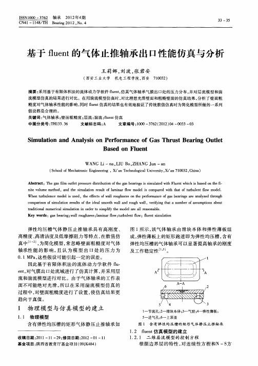
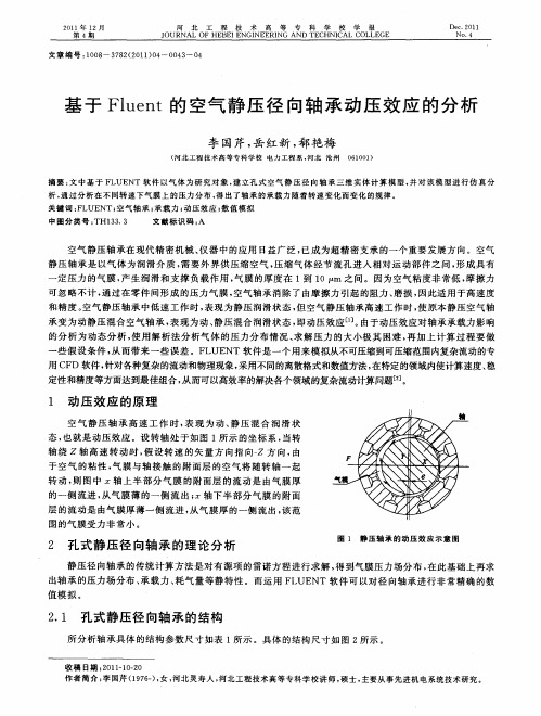
图1 所示 , 气 体 轴 承 由滑 块 本 体 和 弹 性 薄板 组 该 成, 弹性 薄板上 的矩 形 跑 道 即为 弹性 均 压 槽 , 有 含 弹性 均压 槽 的气体 轴 承可 以显著 提 高 轴 承 的刚 度
及工 作稳 定性 , 。
cm a sno s ua o sl fh el m o a n og a , e  ̄i a anmbr f su pi s bu o p ro f i linr ut o ei a s ot w l druhw l vr n t t u e sm t n o t i m t e s t d h l a l i gh oa o a
ta i o a u r a i l t n i r e i l y t e mo e r l r a o a l . r dt n ln me c lsmu ai n o d rt s i i o o mp i h d lae a l e s n be f
Ke r s a e r g; a l o g n s ;a n rf w;u b ln o y wo d :g sb a n w u h e s l mi a o tr u e t w;f e t i lt n i l r l l f l n mu a i u s o! Q 二 兰 Z源自轴承2 1 年4 0 2 期
C 1—1 4 / Be rn 01 No 4 N4 1 8 TH a g 2 2, . i
基于 f et l n 的气体止推轴承 出 口性能仿真 与分析 u
王莉娜 , 刘波 , 张君安
( 西安工 业大学 机 电工程学院, 西安 703 ) 10 2
流 和湍 流模 型进行 对 比。 由于 气体 轴 承 的工作 表 面不 可能 绝 对 光 滑 , 以在 采 用 湍 流 模 型 仿 真 的 所 过程 中 , 壁 面粗糙 度 进行 了设 置 , 仿 真结 果 更 对 使
基于fluent的高精度气体静压轴承性能分析
基金项目:国家科技重大专项“大口径平面快速抛光机 床研制”(2017ZX04022001-202);国防科工局基础产品创新计 划车用动力科研专项 (DEDPZF)。
师 ,2016(11):74-77. [2] 航空弹射救生发射过程视景仿真技术研究 [D]. 中北大学 ,2015. [3] 冯卫权 . 某型飞机后椅启动时前椅弹射自动控制改进技术研究
[J]. 飞机设计 , 2016(1):68-73. [4] 关焕文 , 林贵平 , 宋文娟等 . 飞机救生爆炸切割冲击防护技术研
究 [J]. 火工品 ,2015(5):17-20. [5] 王炜 . 弹射救生技术的发展 [J]. 国际航空 ,2017. [6] 李 锋 , 姚 富 宽 . 某 型 飞 机 弹 射 救 生 分 离 特 性 仿 真 [J]. 飞 机 设
计 ,2016(1):61-67.
China 中国 Plant 设备
Research and Exploration 研究与探索·工艺与技术
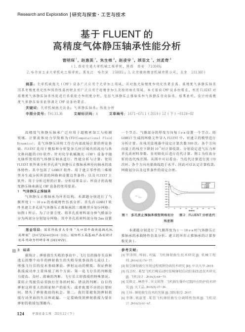
基于 FLUENT 的 高精度气体静压轴承性能分析
曹明琛 1,赵惠英 1,朱生根 2,赵凌宇 1,顾亚文 1,刘孟奇 3 (1. 西安交通大学机械工程学院,陕西 西安 710049;
2. 哈尔滨工业大学机电工程学院,黑龙江 哈尔滨 150001;3. 北京微纳精密机械有限公司,北京 101300)
124 中国设备工程 2019.12 ( 下 )
基于FLUENT的气体静压轴承数值仿真与实验研究

基于FLUENT的气体静压轴承数值仿真与实验研究吴定柱;陶继忠【摘要】应用基于有限体积法的计算流体动力学软件FLUENT进行数值模拟,对影响气体静压止推轴承静态性能的相关因素进行了分析研究,并给出了相应的变化曲线.在自行研制的实验平台上进行气体静压实验,实验与数值模拟计算的结果取得了较好的一致性,证明了将该方法应用在气体润滑领域的可行性,也为进一步改进小孔节流气体静压止推轴承的设计和改善、提高其性能提供了理论依据.【期刊名称】《机械设计与制造》【年(卷),期】2010(000)005【总页数】2页(P150-151)【关键词】空气静压轴承;有限体积法;静态特性【作者】吴定柱;陶继忠【作者单位】中国工程物理研究院,机械制造工艺研究所,绵阳,621900;中国工程物理研究院,机械制造工艺研究所,绵阳,621900【正文语种】中文【中图分类】TH117.21 引言气体静压轴承采用气体作为润滑介质,在轴承的活动面与静止面之间构成气膜,产生承载力,使二者避免接触,具有精度高、无磨损和寿命长的优点。
基于气体静压轴承的以上优点,其在精密工程、超精密工程、微细工程、空间技术、电子精密仪器、医疗器械及核子工程等领域中,有着十分广阔的应用[1][2]。
本文应用基于有限体积法的计算流体动力学软件FLUENT,对气体静压圆盘止推轴承内部流体的流动进行数值计算,给出了轴承的结构尺寸、供气压力等因素对气体静压轴承承载力和静态刚度的影响关系。
在自行研制的实验台上进行气体静压止推轴承实验,由此得到轴承的静态性能。
实验结果和理论计算之间的吻合良好,从而说明数值模拟的可行性。
2 数学模型的建立气体静压止推轴承结构,如图1 所示。
图1 小孔节流圆盘止推气体静压轴承当供气源气体压力为Ps时,气体经过节流孔后产生压降,在节流小孔与气膜间隙过度处压力降至Pd,然后沿着气膜间隙向外流动,在出口处压力为环境压力Pa。
由于空气静压止推轴承的两润滑面通常都是金属,轴承工作过程中产生的热量绝大部分随气体排出或由金属传递出去,故气体润滑过程可看成等温过程[4]。
基于FLUENT的径向静压气体轴承的静态特性研究
基于FLUENT的径向静压气体轴承的静态特性研究于贺春;马文琦;王祖温;徐立芳【期刊名称】《润滑与密封》【年(卷),期】2009(034)012【摘要】以径向静压气体轴承为研究对象,研究动压效应及偏心率对轴承静态特性的影响,采用三维建模,结构化和非结构化网格相结合,运用有限体积法对三维稳态可压缩N-S方程进行求解.结果表明:承载能力随着偏心率的增大而增大;大偏心率高转速时,动压效应对承载能力的影响不可以忽略;大偏心率时,随着转速增加,沿旋转方向,最小气膜间隙处的压力分布不断增大;当转子静止时,刚度随偏心率的增大而先增大后减小;高转速时,刚度随偏心率增加而增加;计算结果与试验结果的对比表明该计算方法能够有效进行径向静压气体轴承流场特性分析.【总页数】5页(P77-81)【作者】于贺春;马文琦;王祖温;徐立芳【作者单位】大连海事大学交通与物流工程学院,辽宁大连,116026;大连海事大学交通与物流工程学院,辽宁大连,116026;大连海事大学交通与物流工程学院,辽宁大连,116026;大连海事大学交通与物流工程学院,辽宁大连,116026【正文语种】中文【中图分类】TG133.36【相关文献】1.基于FLUENT的小孔深浅腔动静压气体轴承静特性研究 [J], 李树森;潘春阳2.单狭缝节流径向静压气体轴承的静态特性研究 [J], 于贺春;李欢欢;胡居伟;张国庆;马文琦;赵则祥3.基于ANSYS-FLUENT的高精密液体静压径向轴承动静态特性研究 [J], 赵春明;马平;龚乘龙;牛兴4.基于Matlab的径向小孔节流静压气体轴承静态特性分析 [J], 李树森;元月;王也5.新型径向槽结构静压气体轴承静态特性研究 [J], 于普良; 胡江山; 李双; 秦丽; 黄千稳; 严迪因版权原因,仅展示原文概要,查看原文内容请购买。
基于FLUENT的轴承腔封严引气流动特性仿真分析及结构优化
基于FLUENT的轴承腔封严引气流动特性仿真分析及结构优
化
冷子昊;程荣辉;郭松;张杰一;苏壮
【期刊名称】《机械工程师》
【年(卷),期】2024()3
【摘要】为降低轴承腔封严引气流阻,提升滑油系统封严可靠性,以航空发动机轴承腔封严引气结构为研究对象,针对发动机典型工况点,将引气管、轴心引气等三维模型导入CFD软件平台FLUENT划分网格,采用Realizable k-ε模型对流场进行三维数值模拟,流场分析结果与实际相吻合,能够准确地反映气体流动状态。
通过对2种引气管结构与3种轴心引气结构流动特性进行对比分析,得到典型工况下封严引气结构的流阻及出口流速等性能参数,最终确定多种封严引气结构对流动特性的影响,从而对引气结构进行改进设计,优化了引气流动特性,为轴承腔封严引气结构设计提供了参考。
【总页数】5页(P47-51)
【作者】冷子昊;程荣辉;郭松;张杰一;苏壮
【作者单位】中国航发沈阳发动机研究所;中国航空发动机集团航空发动机动力传输重点实验室
【正文语种】中文
【中图分类】V233.41
【相关文献】
1.基于Fluent的滑阀阀口流动特性仿真分析
2.基于Fluent的轴承腔温度场仿真分析
3.基于Fluent的带反洗阀封隔器的流阻特性仿真分析
4.基于Fluent的3D打印机成型腔内气固两相流动特性
5.基于Fluent的气液两相流喷嘴内部流动特性仿真
因版权原因,仅展示原文概要,查看原文内容请购买。
基于Fluent的微孔节流气体静压止推轴承的参数设计与研究
基于Fluent的微孔节流气体静压止推轴承的参数设计与研究于贺春;王广洲;王文博;张国庆;赵则祥
【期刊名称】《机床与液压》
【年(卷),期】2018(46)13
【摘要】为提高气体静压止推轴承的静态特性,针对所提出的微孔节流气体静压止推轴承,采用基于有限体积法的CFD软件Fluent进行三维建模仿真,分析了供气孔数目n、量纲一的供气孔分布半径M、供气孔直径d对轴承静态特性的影响规律.按照最大刚度原则,得到如下结论:供气孔数目n在180附近、量纲一的供气孔分布半径M约为0.7、供气孔直径d取最大值0.1 mm时,微孔节流气体静压止推轴承的静态特性最佳.
【总页数】4页(P130-133)
【作者】于贺春;王广洲;王文博;张国庆;赵则祥
【作者单位】中原工学院机电学院,河南郑州450007;中原工学院机电学院,河南郑州450007;中原工学院机电学院,河南郑州450007;中原工学院机电学院,河南郑州450007;中原工学院机电学院,河南郑州450007
【正文语种】中文
【中图分类】TH138;TH133.35
【相关文献】
1.小孔节流式盘状静压止推气体轴承主要几何参数的设计 [J], 郭良斌;宣立明;王卓;彭宝林
2.基于FLUENT的环面节流静压气体圆盘止推轴承二维流场仿真分析 [J], 于贺春;马文琦;王祖温
3.基于静特性分析的环面节流静压圆盘止推气体轴承参数设计 [J], 郭良斌
4.微孔节流气体静压止推轴承的静态特性研究 [J], 张素香;王仁宗;王广洲
5.微孔节流器静压气体止推轴承性能分析 [J], 罗舒元;刘波;赵晓龙;董皓;张君安因版权原因,仅展示原文概要,查看原文内容请购买。
- 1、下载文档前请自行甄别文档内容的完整性,平台不提供额外的编辑、内容补充、找答案等附加服务。
- 2、"仅部分预览"的文档,不可在线预览部分如存在完整性等问题,可反馈申请退款(可完整预览的文档不适用该条件!)。
- 3、如文档侵犯您的权益,请联系客服反馈,我们会尽快为您处理(人工客服工作时间:9:00-18:30)。
Large eddy simulation of vortex shedding and pressurefluctuation in aerostatic bearingsJincheng Zhu a,Han Chen a,b,Xuedong Chen a,na State Key Laboratory of Digital Manufacturing Equipment and Technology,Huazhong University of Science and Technology,Wuhan430074,Chinab Department of Mechanics,Huazhong University of Science and Technology,Wuhan430074,Chinaa r t i c l e i n f oArticle history:Received21May2012Accepted5March2013Available online28April2013Keywords:Aerostatic bearingLarge eddy simulationVortex sheddingPressure fluctuationVibrationa b s t r a c tIn aerostatic bearings,high speed air flow may induce small vibration,which has beenharmful to the improvement of moving and positioning accuracy of aerostaticallysupported devices in ultra-precision applications.In this paper,the transient flow fieldin the aerostatic bearing is numerically investigated using the large eddy simulationmethod.Turbulent structures are studied and vortex shedding phenomenon is discoveredin the bearing recess.Our computational results demonstrate that vortex shedding causespressure fluctuation in the bearing clearance.Relationship between pressure fluctuationand bearing vibration is established based on our simulation results and experimentallymeasured vibration strength.&2013Elsevier Ltd.All rights reserved.1.IntroductionAerostatic bearings have been widely used in ultra-precision moving and positioning equipments.Due to the merit of near-zero friction and low heat generation,applications of aerostatic bearings make it possible for supported devices to realize nanometer positioning accuracy.However,with the increasing demand of positioning accuracy,the inherent small vibration on the order of nanometers(Kawai et al.,2005)severely damages stability and precision of the bearing,especially in sub-nanometer positioning equipments.To understand and eventually suppress this harmful vibration,traditional design and analysis methods for mass flow rate and load carrying capacity do not suffice anymore,and lots of research efforts have been made on the air flow field in aerostatic bearings.Recently,the relationship between the high speed air flow and the small vibration in aerostatic bearings has been realized by many researchers.Kawai et al.(2005)studied the nano-vibration in ultra-precision machine tools and attributed it to air turbulence due to bearing surface roughness.Chen and He(2006)found vortex flow structures in the bearing recess by computational fluid dynamics(CFD)simulation of the steady air flow field,and suggested that these air vortices are responsible for the instability of the aerostatic bearing.Aoyama et al.(2006)also observed this air vortex flow by CFD simulation and reached a similar conclusion,and accordingly proposed a new restrictor design to weaken the vibration. Zhang et al.(2007)analyzed the high Reynolds number(Re)flow in the bearing clearance,and reduced the vibration of aerostatic bearings by flow laminarization.In a recent work,Yoshimura et al.(2012)attributed nano-vibration of aerostatic bearings with surface restriction to pressure fluctuation at the bearing outlet due to atmospheric turbulence.Although the flow-induced nature of bearing vibration has generally been recognized,the previous works only assumed a steady flowContents lists available at SciVerse ScienceDirectjournal homepage:/locate/jfsJournal of Fluids and Structures0889-9746/$-see front matter&2013Elsevier Ltd.All rights reserved./10.1016/j.jfluidstructs.2013.03.012n Corresponding author.Tel./fax:+862787557325.E-mail address:chenxd@(X.Chen).Journal of Fluids and Structures40(2013)42–51field or averaged the flow field in a Reynolds Averaged Navier –Stokes (RANS)sense.Since this flow-induced vibration is apparently a time dependent process,time dependent is necessary to investigate the transient air flow field in the bearing clearance in order to further understand this harmful small vibration.To numerically analyze the detailed flow characteristics in aerostatic bearings,the full Navier –Stokes equations for compressible fluids have to be solved.Since the high speed air flow in the bearing gap near the orifice outlet is turbulent,RANS simulation is usually employed,and numerical results demonstrate adequate accuracy in predicting mean flow characteristics (Chen and He,2006;Li and Ding,2007).Pressure depressions (Eleshaky,2009;Yoshimoto et al.,2007)and vortex flow structures (Chen et al.,2011)near the orifice outlet have also been reported using RANS simulation.However,RANS simulation adopts a statistical turbulent model and details of turbulent structures remain unresolved.Ideally,direct numerical simulation (DNS)can resolve the whole spectrum of turbulent scales as no turbulent model is assumed,but its computational cost is prohibitively huge.In large eddy simulation (LES),large scale turbulent eddies are solved directly and small scale turbulence is modeled by sub-grid scale models.Thus,coherent turbulent structures can be obtained with acceptable computational cost in LES,which has been validated in various applications (Cheng et al.,2012;Lam et al.,2010;Tucker,2011).In a previous study (Chen et al.,2011),steady RANS simulation method was used to study air flow fields in various aerostatic bearings with different parameters and recess shapes,and the relationship between vortex strength and vibration energy of the bearing was established.However,no transient flow characteristics in the aerostatic bearing could be resolved.In this paper,the transient air flow field is investigated numerically using the LES method.Our simulation results reveal vortex shedding and pressure fluctuation in the bearing recess.Vibration of the bearing is also measured experimentally,and it is demonstrated that vibration strength of the bearing increases with increasing pressure fluctuation induced by vortex shedding in the bearing recess.2.Numerical modeling 2.1.LESIn LES,large eddies of turbulence are directly resolved and eddies with scales smaller than grid spacing are modeled.The governing equations employed in LES are the time-dependent Favre Filtered Navier –Stokes equations,including continuity and momentum equations:∂ρ∂t þ∂∂x iðρ~ui Þ¼0;ð1Þ∂ðρ~u i Þþ∂j ðρ~u i ~u j Þ¼−∂p i þ∂~s ij j −∂jð~τij Þ;ð2Þthe Favre filter is the density-weighted filter,where density and pressure are spatial filtered (denoted by “–”)while velocityis density-weighted (e üρÃ=ρ,n denotes a general variable).In Eq.(2),s ij is the viscous stress tensor and τij is the subgrid-scale (SGS)stress,which are defined as~s ij ¼μ∂~u i ∂x j þ∂~u j ∂x i −23δij ∂~u k ∂x k;ð3Þ~τij ¼ρðu i u j $−~ui ~u j Þ;ð4ÞJ.Zhu et al./Journal of Fluids and Structures 40(2013)42–5143where τij needs to be modeled using a SGS rge turbulent eddies can be resolved directly by Eqs.(1)and (2),and turbulent eddies with scales smaller than grid size are modeled.As a SGS model,the Wall-Adapting Local Eddy-Viscosity (WALE)model (Nicoud and Ducros,1999)is adopted in this paper.In this work,LES simulations were performed in the CFD software ANSYS Fluent using the finite volume method.In Fluent,the Pressure-Implicit with Splitting of Operators (PISO)algorithm (Issa,1986)is adopted as the pressure –velocity coupling scheme.In order to minimize numerical dissipation,the second order upwind interpolation is chosen for the density,turbulent kinetic energy and turbulent dissipation rate,while the bounded central differencing is chosen for momentum interpolation in LES.As the transient formulation,the second order implicit scheme is adopted.The Non-Iterative Time-Advancement (NITA)scheme (Issa,1986)is used to improve the computational efficiency,and the time step size Δt ¼1Â10−8s is chosen according to the CFL condition u Δt =Δx o 1,where Δx is the size of control putational domainFor generality and simplicity,a circular pad aerostatic bearing with a single central orifice restrictor is considered as shown in Fig.1.The outer diameter of the bearing is d 2¼20mm and the orifice diameter is d 0¼0.15mm.The cylindrical recess has a diameter d 1¼3mm and depth H ¼0.1mm.The air film thickness is h ¼10μm.In our LES calculations,the air flow domain is divided into 12sections along the circumferential direction,and only one section (Fig.2)is used as the computational domain to reduce the computational cost.This simplification is reasonable for qualitative study on turbulent structures in the aerostatic bearing.In order to allow for a fine resolution of turbulent structures in the bearing recess,the Embedded LES (ELES)modeling technique in Fluent is adopted.Specifically,the computational domain is divided into three regions:orifice,recess and gas film (Fig.2).The realizable k −εmodel is used in the orifice region (RANS region);the flow in the air film is supposed to be laminar and LES is adopted in the recess region.An RANS –LES interface is used to connect the orifice region and the recess putational meshFig.3shows the computational mesh used in the LES,where non-conformal mesh is used.It is known that the accuracy of LES is sensitive to mesh resolution,so more refined mesh is generated in the recess region.Mesh independence tests (see Table 1)are performed until further refinement of the mesh results in insignificant changes in thecomputationalFig.1.Schematic of the aerostatic bearing.putational domain and ELES model.J.Zhu et al./Journal of Fluids and Structures 40(2013)42–5144results.The parameters in Table 1are described as follows.The total number and the volume of the mesh in various regionsare listed.The non-dimensional distance y +can reflect wall-adjacent mesh resolution,which is defined as y þ¼ffiffiffiffiffiffiffiffiρτw p y =μ,where y is the distance from the wall to the center of the first neighboring mesh,and τw is the wall shear stress.To resolve accurately turbulent eddies in the near-wall regions,y +is always guaranteed to be less than 1with local mesh refinement.As the calculation results,the mean values and the standard deviations of p A are compared between the coarse mesh case and the fine mesh case,where p A is the time variation (as described in Section 3.2)of area-weighted averaged pressure on the wall 2.2.4.Boundary and initial conditionsAs shown in Fig.2,pressure inlet boundary condition is specified at the orifice inlet,in which turbulent intensities of 1%,5%and 10%are considered;atmospheric pressure is specified at the bearing outlet;two symmetric boundaries are adopted on the two surfaces in the circumferential direction.On the solid walls,no-slip and no heat transfer conditions are specified.In addition,all the walls are assumed to be perfectly smooth.The air used in the simulations is assumed to obey the ideal gas law,hence the density varies according to the state equation.Other physical constants such as viscosity,molecular weight,specific heat and thermal conductivity are 1.7894Â10−5kg/(m s),28.966Â10−3kg/mol,1006.43J/(kg K)and 0.0242W/(m K),respectively.A steady RANS simulation result is used as the initial field of LES,which can help LES to converge quickly.2.5.Validation of numerical modelIn order to justify our numerical model,the existing experiment data (Yoshimoto et al.,2007)of pressure distribution of the aerostatic bearing are utilized as a comparison.Fig.4shows the comparison with our numerical result,where both the realizable k −εRANS result and the LES result are plotted.The LES result is the statistical mean pressure distribution in the bearing clearance.As can be seen in the figure,there is almost no discrepancy between our CFD results and the experimental data except for the region where r /r 2is between 0.034and 0.2.In this region near the orifice outlet,the LES result shows better agreement with experimental data than the RANS one.Therefore,the LES method can be employed in the calculation of the flow field of aerostaticbearings.XZputational mesh.Table 1Mesh refinement study,where Δdenotes mesh volume (μm 3),p A is the time variation of area-weighted averaged pressure (Pa)on the wall 2,E and s denote the mean value and standard deviation,respectively.MeshRecess Orifice Gas film Max y +Total numberMean E ðp A ÞFluctuation s ðp A ÞΔminΔmax Δmin Δmax Δmin Δmax Coarse 1.11129020.6076.271755716101.526807535062862Fine0.434370.651964435046367J.Zhu et al./Journal of Fluids and Structures 40(2013)42–51453.Transient flow characteristics 3.1.Flow structures and vortex sheddingFig.5displays the streamlines and the pressure contours computed from steady RANS simulation when P s ¼4atm,in which flow separation and vortex formation can been seen in the recess near the orifice outlet.It is noted that steady RANS simulation results in axisymmetric flow structures.Fig.6displays the corresponding instantaneous flow field obtained by LES at different times.In Fig.6(a),the iso-surfaces of instantaneous vorticity are depicted.In contrast to the single axisymmetric vortex in Fig.5,the coherent turbulent structure in the recess contains a series of vortices with varying sizes and shapes.The vortex shedding phenomenon can be observed.Specifically,the toroidal spanwise vortices develop after impinging of the orifice outflow on the bottom wall of the bearing,and then stretch in the radial direction along the wall surface with growing size through rolling-up process,and the convected wall vortices quickly break into more sophisticated small eddies downstream and finally are dissipated due to air viscosity.This vortex shedding phenomenon can also be explained as a typical flow pattern of the impinging jet (Lee and Lee,2000),since the high speed orifice outflow impinges perpendicularly on the solid wall.3.2.Pressure depression and fluctuationAs shown in Fig.5,pressure depression (sudden descent and ascent)can be observed near the orifice outlet where the minimum pressure occurs in the vortex core.However,with the vortex shedding displayed in the LES result,more local pressure minima corresponding to vortex centers are induced,as shown in Fig.6(b).Similarly,the positions and the magnitudes of these pressure minima are transiently changing.Fig.7shows an instantaneous pressure distribution on the0246p / P 0r / r 2Fig.4.Pressure distribution along radial direction in the aerostatic bearing:comparison of results among LES,RANS and the existing experiment.Fig.5.Streamlines and pressure contours obtained from steady RANS simulation.J.Zhu et al./Journal of Fluids and Structures 40(2013)42–5146bottom wall (the recess region)of the bearing.It can be seen that the repeated pressure up-and-downs are present not only in the radial direction,but also in the circumferential direction.Fig.8plots pressure variations with time at three different locations (y ¼0.055mm,r ¼0.2,0.5,1.0mm),which are distributed along the radial direction in the bearing recess.Pressure fluctuation can be clearly seen in this figure,which also weakens along the radial direction.Table 1lists some statistical results of the area-weighted averaged pressure variation with time,where s ðp A Þcan represent the intensity of pressure fluctuation.In our simulations,when the intensities of inflow turbulence are respectively set as 1%,5%and 10%,the corresponding s ðp A Þare 62,65and 73,hence the influence of inflow turbulent level on pressure fluctuation is very small.In summary,associated with repeated shedding and downstream advection of vortices is repeated pressure depression (in space)and fluctuation (in time).It should be noted that this repeated pressure depression and fluctuation is not resolvable in RANS due to its essence of statistical averaging.It is manifest that LES results indicate unsteady flow characteristic in the aerostatic bearing even if initial and boundary conditions are all constant.4.DiscussionsAs is known,air supply pressure has a significant influence on the flow field in the aerostatic bearing.Therefore,air supply pressure values are varied in our numerical simulations.Fig.9shows the contours of instantaneous vorticity in the bearing recess when P s ¼2,3and 4atm.From this figure,the air flow is steady and remains in the laminar regime when the supply pressure is 2atm,while becomes unsteady and so vortex shedding is observed in the other two cases.Furthermore,associated with increasing air supply pressure,vorticity magnitude of the flow increases correspondingly.It suggests that the flow in the bearing recess has a transition from lamina to turbulence with increasing supply pressure.The correspondinglocal Reynolds number Re ¼_m=πr μat the recess entrance (r ¼r 0)in each case is calculated,as shown in Table 2.It can be inferred that the flow transition will appear when the local Reynolds number is beyond a certain critical valuebetweenFig.6.Iso-surfaces of instantaneous vorticity (a)and pressure (b).J.Zhu et al./Journal of Fluids and Structures 40(2013)42–51471000and 1500.Once beyond this critical Reynolds number,the air flow is turbulent and so results in pressure fluctuation.It can be observed from Fig.10that this pressure fluctuation becomes more severe as supply pressure increases.For comparison,the transient flow field of the non-recessed bearing (other dimensions being the same)is also calculated.Fig.11displays the instantaneous flow field obtained from LES,where the streamlines show that only one tiny vortex is present near the orifice outlet,and the flow is steady and no air vortex shedding appears.The absence of vortex shedding in the non-recessed bearing can also be explained by the smaller Reynolds number which confines the local flow in a laminarregime.Fig.7.Instantaneous pressure distribution on the bottom wall (the recess region)of the bearing.3.403.443.483.523.56p (P a )5Fig.8.Time 1.0mm).Fig.9.Contours of instantaneous vorticity under different supply pressure values.J.Zhu et al./Journal of Fluids and Structures 40(2013)42–5148-300-1500150300t (ms)f o n o i t a u t c u l F P A (P a )Fig.10.Pressure fluctuations with different supply pressurevalues.Fig.11.Instantaneous flow field of non-recessed bearing.Fig.12.Photo of experimental set-up.Table 2Local Reynolds number computed in different cases.Case Recess P s (atm)_m(kg/s)Re 1Yes 2 2.66Â10−66312Yes 3 6.39Â10−615163Yes 4 1.06Â10−525154No44.52Â10−61070J.Zhu et al./Journal of Fluids and Structures 40(2013)42–5149Vibration of the recessed bearing and the non-recessed bearing is also experimentally measured.Fig.12shows our experimental set-up.The two bearing pads have the same surface roughness.The tested bearing is placed on a marble base (with roughness less than 1μm),and air supply pressure can be regulated with a proportional throttle valve.External loads are applied on top of the aerostatic bearing.The parallelization of the bearing is assured by the displacement sensor (LVDT)which measures the bearing clearance height at three locations.Signals of the vibration acceleration of the aerostatic bearing are obtained by an accelerometer (PCB CA-YD-106),a data acquisition device (LMS SCADAS III),and a data analysis software platform (LMS Test Lab).The spectrum characteristics of bearing vibration acceleration are plotted in Fig.13.It can be seen that the amplitude of vibration acceleration increases with increasing air supply pressure,and the vibration of the non-recessed bearing (Fig.13(b))is much weaker than that of the recessed bearing (Fig.13(a)).Comparing our LES and experimental results,the qualitative behavior of pressure fluctuation is consistent with that of the bearing vibration when subjected to the different air supply pressure values.Although the vibration is also measured in the recessed bearing when P s ¼2atm,it may attribute to bearing surface roughness effect.Specially,compared with the results of the recessed bearing,the non-recessed bearing study clearly indicates that the vibration is relatively small when no pressure fluctuation is induced.Therefore,it can be concluded that vortex shedding results in remarkable pressure fluctuation and can induce small vibration of aerostatic bearings.5.ConclusionsThis paper is focused on the transient flow characteristics in ultra-precision aerostatic bearings.In order to capture turbulent structures and fluctuations,LES method is employed to numerically calculate the transient flow field in the bearing clearance.Vortex structures and pressure fluctuation in the bearing clearance are analyzed.Qualitative behavior of pressure fluctuation,as well as vibration of aerostatic bearing,is also discussed.If ever possible,however,the quantity analysis of the relationship between pressure fluctuation and small vibration of aerostatic bearings is needed in the future work.From the results in this paper,the following conclusions can be drawn:1.Vortex shedding is present in the aerostatic bearing recess for sufficiently large air supply pressure,i.e.,air vortices are repeatedly generated,shed,advected downstream and dissipated.2.Repeated pressure depression (in space)and fluctuation (in time)can be observed in the bearing clearance when vortex shedding occurs.3.Once the flow Reynolds number is beyond a certain value at the recess inlet,vortex shedding in the bearing clearance results in remarkable increase of pressure fluctuation and vibration of the aerostatic bearing.AcknowledgmentsThis study was supported by the National Basic Research and Development Program of China (No.2009CB724205)and the National Natural Science Foundation of China (Nos.51121002and51175196).Fig.13.Influence of air supply pressure on vibration acceleration of the aerostatic bearings in frequency domain.(a)Recessed bearing and (b)non-recessed bearing.J.Zhu et al./Journal of Fluids and Structures 40(2013)42–5150J.Zhu et al./Journal of Fluids and Structures40(2013)42–5151 ReferencesAoyama,T.,Kakinuma,Y.,Kobayashi,Y.,2006.Numerical and experimental analysis for the small vibration of aerostatic guideways.CIRP Annals—Manufacturing Technology55(1),419–422.Chen,X.,Chen,H.,Luo,X.,Ye,Y.,Hu,Y.,Xu,J.,2011.Air vortices and nano-vibration of aerostatic bearings.Tribology Letters42(2),179–183.Chen,X.,He,X.,2006.The effect of the recess shape on performance analysis of the gas-lubricated bearing in optical lithography.Tribology International39(11),1336–1341.Cheng,S.Y.,Tsubokura,M.,Nakashima,T.,Okada,Y.,Nouzawa,T.,2012.Numerical quantification of aerodynamic damping on pitching of vehicle-inspired bluff body.Journal of Fluids and Structures30,188–204.Eleshaky,M.E.,2009.CFD investigation of pressure depression in aerostatic circular thrust bearings.Tribology International42(7),1108–1117.Issa,R.I.,1986.Solution of the implicitly discretised fluid flow equations by operator-splitting.Journal of Computational Physics62(1),40–65.Kawai,T.,Ebihara,K.,Takeuchi,Y.,2005.Improvement of machining accuracy of5-axis control ultraprecision machining by means of laminarization and mirror surface finishing.CIRP Annals—Manufacturing Technology54(1),329–332.Lam,K.,Lin,Y.F.,Zou,L.,Liu,Y.,2010.Investigation of turbulent flow past a yawed wavy cylinder.Journal of Fluids and Structures26,1078–1097.Lee,J.,Lee,S.J.,2000.The effect of nozzle aspect ratio on stagnation region heat transfer characteristics of elliptic impinging jet.International Journal of Heat and Mass Transfer43(4),555–575.Li,Y.,Ding,H.,2007.Influences of the geometrical parameters of aerostatic thrust bearing with pocketed orifice-type restrictor on its performance.Tribology International40(7),1120–1126.Nicoud,F.,Ducros,F.,1999.Subgrid-scale stress modelling based on the square of the velocity gradient tensor.Flow,Turbulence and Combustion62(3), 183–200.Tucker,P.G.,putation of unsteady turbomachinery flows:Part2—LES and hybrids.Progress in Aerospace Sciences47(7),546–569. Yoshimoto,S.,Yamamoto,M.,Toda,K.,2007.Numerical calculations of pressure distribution in the bearing clearance of circular aerostatic thrust bearings with a single air supply inlet.Journal of Tribology—Transactions of the ASME129(2),384–390.Yoshimura,T.,Hanafusa,T.,Kitagawa,T.,Hirayama,T.,Matsuoka,T.,Yabe,H.,2012.Clarifications of the mechanism of nano-fluctuation of aerostatic thrust bearing with surface restriction.Tribology International48,29–34.Zhang,M.,Zhu,Y.,Ren,G.,Duan,G.,Gao,G.,2007.Finite element and experimental analysis on micro-vibration of ultra precision air bearing linear motion stage and methods of its elimination.In:Proceedings of ASME1st International Conference on Integration and Commercialization of Micro and Nanosystems,Parts A and B,pp.83–87.。