Polaris_Vicra and Polaris_Spectra_Gaitech
奥林巴斯光谱分析仪应用领域英文版
奥林巴斯光谱分析仪应用领域英文版Olympus handheld spectrometer has the characteristics of fast, non-destructive and high precision when testing. After years of continuous development and improvement, it has been widely used in all walks of life.The handheld spectrometer is a kind of spectral analysis instrument. Based on XRF spectral analysis technology, when the high-energy X-ray in the inner layer of the atom collides with the atom, an inner electron will be expelled, resulting in a hole, making the whole atomic system in an unstable state. When the electrons in the outer layer jump into the hole, the photons may be absorbed again, and the Auger effect will occur when another secondary photoelectron in the outer layer is expelled, The secondary photoelectrons expelled are called Auger electrons. This is how the handheld spectrometer works.Handheld spectrometers are widely used in metallurgy, geology, nonferrous metals, building materials, commodity inspection, environmental protection, health and other fields, especially in the field of RoHS detection.1. Alloy material analysisAt present, in the field of alloy material testing, it is mainly used for the on-site determination of elementcomposition in metal materials in military, aerospace, steel, petrochemical, electric power, pharmaceutical and other fields. It is an indispensable rapid component identification tool in the industrial and military manufacturing fields with the rise of the world economy.2. Heavy metal detectionIn addition to the traditional alloy material detection, precious metals, ROHS compliance screening, ore analysis, handheld XRF instruments also play an important role in geological exploration and environmental assessment. By analyzing the heavy metal elements in the soil, we can know the mineral distribution and pollution distribution of the whole region.3. Other areasXRF technology can also be used in some new fields, such as wind power and automobile. By detecting the content of metal elements in oil, the wear of bearings can be indirectly reflected.Many new XRF application fields are being developed, which makes XRF technology widely used in various industries. For example, XRF alloy analyzer is also used for welding quality control in the production and manufacturing process of thefactory.。
NDI 激光立体扫描仪应用案例三则
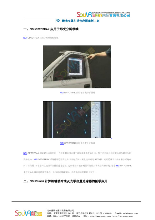
NDI 激光立体扫描仪应用案例三则一、NDI OPTOTRAK应用于形变分析领域NDI OPTOTRAK应用于形变分析领域NDI OPTOTRAK应用于形变分析领域NDI OPTOTRAK应用于形变分析领域NDI OPTOTRAK测量解决方案的每一个应用都特别适用于对零部件形变的分析。
基于光学技术和捕捉动态与静态为形变的能力,NDI OPTOTRAK系统能够追踪高达512目标点同时测量速率可达4600/秒。
它经特殊设计的附着于兴趣点的目标范围,可让您可以记录零部件的静态定位。
定制化软件能够测量零部件大小和方向的形变。
这令NDI OPTOTRAK 系统成为众多应用的理想选择,包括固定装置弹回、热变形和风荷载形(未完)二、NDI Polaris计算机辅助疗法及光学位置追踪器的医学应用在治疗疾病过程中,医生进行手术时面临着挑战,他们需要在导航解剖人体及病变组织的同时最大限度地减少对周围健康组织的损害。
计算机辅助疗法(CAT)和计算机辅助手术(CAS)解决方案,能帮助医生解决此类问题。
最终这种革命性的疾病状况诊疗方式最大限度地减少这些手术的外力侵入损伤,改善治疗效果,并减少并发症从而提高安全性。
NDI Polaris计算机辅助疗法及光学位置追踪器的医学应用将Polaris Spectra®光学测量系统与CAT应用整合,使医生能够克服这些挑战,更好地目标化病变组织同时保留健康组织。
整合Polaris Spectra将如何实现以上效果?将NDI标记点定位于在手术中将要使用的关键工具上和患者身上,这样就可以利用Polaris Spectra位置传感器来追踪这些工具及患者。
一旦位置传感器能够跟踪工具和患者,它就可以计算出每个目标点的确切位置和方向。
了解了该位置和方向信息,患者的身体位置可以与术(未完)三、NDI Polaris在计算机辅助治疗颅内手术中的应用计算机辅助治疗系统有很大潜力,用来提高手术的操作精度并缩短患者恢复时间。
红外光谱特征峰对照表英文
红外光谱特征峰对照表英文Infrared Spectroscopy Characteristic Peak Reference Table.Infrared spectroscopy is a valuable tool for the identification and characterization of compounds, as it provides information about the vibrations of the chemical bonds within a molecule. The infrared spectrum is typically divided into several regions based on the frequency of the vibrations, and each region corresponds to different typesof chemical bonds and vibrations. In this article, we will discuss the characteristic peaks commonly observed in infrared spectroscopy and provide an infrared spectroscopy characteristic peak reference table.1. Aromatic C-H Stretching Vibrations: 3100-3020 cm^-1。
This region corresponds to the stretching vibrations of aromatic C-H bonds. The presence of peaks in this region indicates the presence of aromatic rings in the molecule.2. Alkyl C-C Stretching Vibrations: 1450-1375 cm^-1。
NDI_Combined_API_Sample_User_Guide_Rev4_(IL-1070108)
NDI Combined API SampleUser GuideRevision 4April 2008IMPORTANTPlease read this entiredocument before using theNDI Combined API SampleRevision StatusRevision Number Date Description1September 2005First release, for version 2.01 ofNDI Combined API Sample 2September 2005Updated for version 3.01 of NDICombined API Sample3June 2006Updated for version 3.02 of NDICombined API Sample4April 2008Removed reference to wirelesscommunications (Bluetooth).Part number: IL-1070108Copyright 2005-2008 Northern Digital Inc. All Rights Reserved.p Printed in Canada.Disclaimer of Warranties and Limitation of LiabilityPublished by:Northern Digital Inc.103 Randall Dr.Waterloo, Ontario, Canada N2V 1C5Telephone:+1 (519) 884-5142Toll Free:+1 (877) 634 634 0Global:++ (800) 634 634 00Facsimile:+1 (519) 884-5184Website:Copyright 2005-2008, Northern Digital Inc.All rights reserved. No part of this document may be reproduced, transcribed, trans-mitted, distributed, modified, merged, translated into any language or used in any form by any means - graphic, electronic, or mechanical, including but not limited to photocopying, recording, taping or information storage and retrieval systems - without the prior written consent of Northern Digital Inc. Certain copying of the software included herein is unlawful. Refer to your software license agreement for information respecting permitted copying.Disclaimer of Warranties and Limitation of LiabilitiesNorthern Digital Inc. has taken due care in preparing this document and the programs and data on the electronic media accompanying this document including research, development, and testing.This document describes the state of Northern Digital Inc.’s knowledge respecting the subject matter herein at the time of its publication, and may not reflect its state of knowledge at all times in the future. Northern Digital Inc. has carefully reviewed this document for technical accuracy. If errors are suspected, the user should consult with Northern Digital Inc. prior to proceeding. Northern Digital Inc. makes no expressed or implied warranty of any kind with regard to this document or the programs and data on the electronic media accompanying this document.Northern Digital Inc. makes no representation, condition or warranty to the user or any other party with respect to the adequacy of this document for any particular pur-pose or with respect to its adequacy to produce a particular result. The user’s right to recover damages caused by fault or negligence on the part of Northern Digital Inc. shall be limited to the amount paid by the user to Northern Digital Inc. for the provi-sion of this document. In no event shall Northern Digital Inc. be liable for special, col-NDI Combined API Sample User Guide - Revision 4lateral, incidental, direct, indirect or consequential damages, losses, costs, charges, claims, demands, or claim for lost profits, data, fees or expenses of any nature or kind.Product names listed are trademarks of their respective manufacturers. Company names listed are trademarks or trade names of their respective companies.NDI Combined API Sample User Guide - Revision 4Table of Contents Table of ContentsRead Me First . . . . . . . . . . . . . . . . . . . . . . . . . . . . . . . . . . . . . . . . . . . . . . .ii Contact Information. . . . . . . . . . . . . . . . . . . . . . . . . . . . . . . . . . . . . . . .ii Updates. . . . . . . . . . . . . . . . . . . . . . . . . . . . . . . . . . . . . . . . . . . . . . . . . .ii1 Overview. . . . . . . . . . . . . . . . . . . . . . . . . . . . . . . . . . . . . . . . . . . . . . . .1 1.1 What is the NDI Combined API Sample?. . . . . . . . . . . . . . . . . . .1 1.2 Requirements. . . . . . . . . . . . . . . . . . . . . . . . . . . . . . . . . . . . . . . . .1 1.3 Installation . . . . . . . . . . . . . . . . . . . . . . . . . . . . . . . . . . . . . . . . . . .22 Using NDI Combined API Sample . . . . . . . . . . . . . . . . . . . . . . . . . . .3 2.1 Settings. . . . . . . . . . . . . . . . . . . . . . . . . . . . . . . . . . . . . . . . . . . . . .3 2.2 System Communication Commands . . . . . . . . . . . . . . . . . . . . . . .4 2.3 Extras. . . . . . . . . . . . . . . . . . . . . . . . . . . . . . . . . . . . . . . . . . . . . . .43 Source Code Explanation. . . . . . . . . . . . . . . . . . . . . . . . . . . . . . . . . .7 NDI Combined API Sample User Guide - Revision 4iRead Me FirstRead Me FirstThis guide supports the NDI Combined API Sample, version 3.02.For more information on the API, see:•For Aurora: the “NDI Polaris and Aurora CombinedApplication Programmer’s Interface Guide.”•For Polaris, Polaris Vicra, and Polaris Spectra: the “Polaris Application Program Interface Guide.”Contact InformationIf you have any questions regarding the content of this guide or theoperation of this product, please contact us:UpdatesNDI is committed to continuous improvements in the quality andversatility of its software and hardware. To obtain the best results with your NDI system, check the NDI Support Site regularly for updateinformation:ii NDI Combined API Sample User Guide - Revision 4Overview 1Overview1.1What is the NDI Combined API Sample?NDI Combined API Sample is intended to be used as a sampleexecutable, with the entire source code for the program provided forreference. The source code uses RS-232 communications to illustrate sending commands to and parsing responses from a Polaris System, a Polaris Vicra System, a Polaris Spectra System, or an Aurora System.The source code directory contains all of the files required to build an executable. It includes both source code files and project files.1.2RequirementsSystem RequirementsNDI Combined API Sample is intended to run on Windows NT 4.0, 2000 and XP operating systems.Hardware RequirementsProduct Firmware RevisionPolaris Combined firmware revision 024 or laterPolaris Vicra Combined firmware revision 001 or laterPolaris Spectra Combined firmware revision 002 or laterAurora Combined firmware revision 001 or laterCompiler RequirementsNDI Combined API Sample was created and compiled using Microsoft's Visual C++ 6.0. It has not been tested with other compilers, and thus is not guaranteed to work with other compilers.NDI Combined API Sample User Guide - Revision 41Overview1.3InstallationTo install the NDI combined API sample, copy the contents of the“NDICombinedAPISample” folder from the CD onto the host computer. 2NDI Combined API Sample User Guide - Revision 4Using NDI Combined API Sample2Using NDI Combined API SampleThis sample code uses the NDI Combined API. Some options are system-specific and therefore might not be available for the system you are using.2.1SettingsThe settings are stored in the CombinedAPISample.ini file.Communication SettingsCommunication settings allow you to specify the COM port parameters: port number, data bits, baud rate, stop bits, parity, hardware handshaking, and timeout value. The timeout value is the amount of time the program polls the COM port for a reply before assuming communication has been lost.When you start the NDI Combined API Sample application, make sure that the “Reset hardware upon initialization” option in the COM port settings is selected. To select this option, select Settings > COM Port Settings. Ensure that the “Reset hardware upon initialization” check box contains a check mark.Note If this option is not selected, the hardware will not be set to the correct baud rate when the system is initialized, which can result in acommunications timeout.ROM File SettingsROM file settings allow you to specify the tool definition files (.rom) to be loaded to the system.Illuminator Activation Rate (Polaris and Polaris Spectra only)The illuminator activation rate for the Polaris System and the Polaris Spectra System can be set to 20Hz, 30Hz, or 60 Hz while the system is in any mode except tracking.NDI Combined API Sample User Guide - Revision 43Using NDI Combined API Sample2.2System Communication CommandsReset SystemThis command sends a serial break to the COM port to reset the system, and resets the main dialog.Initialize SystemThis command initializes the system, polls the system for VER andSFLIST information (viewable in System Properties), places the dialog in initialized mode, and determines which type of system is connected.Activate HandlesThis command retrieves or requests port handles, initializes and enables the port handles, loads tool definition files to port handles that have tool definition files specified, and gathers all the information to display under Tool Properties.Start TrackingThis command places the system in tracking mode, and displays thetransformations in the main dialog. You can switch between BX (binary transformations) and TX (text transformations), and specify whether to use the 0x0800 option.Stop TrackingThis command stops tracking and returns the program to setup mode. 2.3ExtrasSystem PropertiesThis dialog displays system properties that are read upon initialization. 4NDI Combined API Sample User Guide - Revision 4Using NDI Combined API SampleCOM Port TimeoutsThe program will timeout if its connection to the system is lost, or if the amount of time required to receive a response from the system exceeds the specified timeout value. In this case, you will be presented with three options:•Retry: attempts to resend the command, and polls for the response for the specified amount of time (timeout value).•Restart: restarts the application and cancels the current COM port communication.•Close Application: closes the application and cancels the current COM port communication.Note For the Polaris and Aurora Systems, the timeout values are specified in the INI file. For the Polaris Vicra and Polaris Spectra Systems, the timeout values are specified in the Info.Timeout.* parameters. Use the GETcommand to view the values of these parameters.Tool PropertiesOnce port handles have been initialized, you can view the handleproperties by selecting the port handle from the combo box located on the main dialog. If the system is not in tracking mode, you have the option of disabling the tool by toggling the Handle Enabled check box.Tracking ModesThe program can report transformations in TX (text transformation) and BX (binary transformation) formats. To change between formats, toggle the radio buttons located on the main dialog. You can also specify the use of the 0x0800 tracking flag, and whether to report transformations as Euler angles instead of quaternion units.Reference HandleIf you select a reference handle, the program will report thetransformations of other tools with respect to the position and orientationUsing NDI Combined API Sampleof the reference tool. The current reference tool is indicated by the letter R in front of its port handle.System InformationThe system information area displays information while tracking. It will display the following:•the frame number•“temperature out of range” and “diagnostic pending” messages (Polaris Vicra and Polaris Spectra only)Click the button to see the diagnostic alert flags (described inmore detail in the “Polaris Application Program InterfaceGuide”).LegendWhile tracking the tool, the Status column in the tracking table will show one of the following:•POOV - the tool is partially out of volume, but can still be tracked by the system. If Report out of volumetransformations is checked, the system will reporttransformations; otherwise, the system will report that the tool ismissing.•OOV - the tool is out of volume, but can still be reported by the system. If ‘Report out of volume transformations’ is checked,the system will report transformations; otherwise, the systemwill report that the tool is missing.•OK - the tool is within the characterized measurement volume and is being tracked.•--- - the system cannot track the tool.Source Code Explanation3Source Code ExplanationCombinedAPISample.cpp This is the source file created by Visual C++ when the project is created. It controls the main dialog.CombinedAPISampleDlg.cpp This is the code for the main dialog. Itcontrols all of the calls made by and to the main dialog. This file controls the creation of the supporting dialogs and the CommandHandling class. It controls the entire user interaction section of the program.Comm32.cpp This is the code for communicating with thecommunications port. It includes code for sending messages to andgetting responses from the system attached to the port. It also has code for opening, initializing and closing the port.CommandConstruction.cpp This is the code to construct a command. It takes a command string, and if specified replaces the space with a ‘:’ and calculates and attaches a CRC for the command. The code also attaches a carriage return to the command.CommandHandling.cpp This is the main class that controls creatingcommands, sending them to the systems, receiving the response, and parsing the response. This routine parses the responses into variables and structures that can be called by the parent class for displaying purposes.ComPortSettings.cpp This is the code that controls the COM PortSettings dialog. It controls all input from the user regarding the COM port and interacts directly with the INI file to both recall and store the information for future reference.ComPortTimeout.cpp This is the code that controls the COM PortTimeout dialog. This dialog is displayed when there has been a timeout while communicating with the system. The dialog gives the user three options: restart the program, retry the command, or close the program.Conversions.cpp This file is responsible for all the math conversions used to change binary and hexadecimal values to the ASCII, integer or float value. These conversions are mainly used while tracking in binary mode.IlluminatorFiringRate.cpp This file controls the Illuminator Activation Rate dialog box. It accepts input from the user for the illuminatoractivation rate (Polaris only). It interacts directly with the INI file to both save and recall the appropriate value.Source Code ExplanationINIFileRW.cpp This file contains all of the routines required forcommunication with the INI file. It has both read and write routines, in order to receive information from and write information to the INI file. It has routines for all variable types that may be read from the INI file.NewAlertFlagsDlg.cpp This file controls the display of Polaris Vicra and Polaris Spectra alerts returned with the alerts parameters.ProgramOptions.cpp This file controls the Program Options dialog box.It accepts input from the user for program files, switches, and flags. It interacts directly with the INI file to both save and recall the appropriate values.ROMFileDlg.cpp This file controls the SROM Image File dialog box. It accepts input from the user for the tool definition files to be virtually loaded to the system. It displays only the ports that are available. Itinitializes the system if the system hasn’t already been initialized. Itinteracts directly with the INI file to both save and recall the appropriate values.SystemCRC.cpp This file contains all of the routines required to calculate CRCs and to verify that the CRCs coming back are valid. These routines are defined in the CommandHandling header file.SystemFeaturesDlg.cpp This file controls the System Features dialog.This dialog displays the features of the currently attached system. Itreceives input from the main dialog and displays information obtained using VER and SFLIST calls.APIStructures.h This header file contains all of the structures andvariables required while parsing information received from the system. Note All .cpp files have corresponding headers (.h extension).IndexIndexAactivate ports 4 APIStructures.h 8CCOM port 3 CombinedAPISample.cpp 7 CombinedAPISample.ini 3 CombinedAPISampleDlg.cpp 7 Comm32.cpp 7 CommandConstruction.cpp 7 CommandHandling.cpp 7 communication settings 3 compiler requirements 1 ComPortSettings.cpp 7 ComPortTimeout.cpp 7 contacting NDI ii Conversions.cpp 7Hhardware requirements 1Iilluminator activation rate 3 IlluminatorFiringRate.cpp 7 information about the system 6 INIFileRW.cpp 8initialize system 4 installing 2NNDI Combined API Sample defined 1installing 2overview 1requirements 1settings 3 NewAlertFlags.Dlg.cpp 8 OOOV 6PPOOV 6ports 4 ProgramOptions.cpp 8Rreference handle 5reset system 4ROM file settings 3 ROMFileDlg.cpp 8IndexSsettings 3system communication 4 system information 6 system properties 4 system requirements 1 SystemCRC.cpp 8 SystemFeaturesDlg.cpp 8Ttimeouts 5tool definition files (.ROM) 3tool port properties 5 tool status 6trackingreference handle 5setting modes 5start tracking 4stop tracking 4system information 6tool status 6Uupdates, obtaining ii。
原位ATR-IR光谱研究钽酸钠光催化全分解水机理

第32卷第4期光散射学报Vol.32No.4 2020年12月THEJOURNAL OFLIGHTSCATTERING Dec.2020文章编号:1004-5929(2020)04-0381-05原位ATR-IR光谱研究n酸钠光催化全分解水机理丁借1!!<涛冯兆池",王秀丽""1催化基础国家重点实验室,中国科学院大连化学物理研究所,大连1160232中国科学院大学,北京100049;3海洋科技与环境学院,大连海洋大学,大连116023)摘要:采用固相反应和浸渍法制备了NiO/NaTaO3:La催化剂。
采用衰减全反射红外光谱原位研究了钮酸钠基光催化剂上光催化全分解水机理。
在光催化反应条件下直接观测到了归属为物理吸附的过氧化氢中间物种的1350cm1和870cm1红外吸收峰。
过氧化氢物种是由水氧化的中间物种Ta(O2)在大量水存在条件下先质子化生成TaOOH中间物种,之后进一步质子化而形成的。
证实了NaTaOs液态光催化和气相光催化分解水的机理是一致的&关键词:光催化全分解水;原位红外;钮酸钠中图分类号:O64文献标志码:A doi:10微3883/j issn1004-5929.202004014Mechanistic Study of Photocatalytic Overall Water SpliUing onNaTaO3-based Photocatalysts by In-Situ ATR-IR SpectroscopyDING Qian1#,CHEN Tao1'3,FENG Zhaochi1*,WANG Xiuli1* (1State Key Labrratrry of Catalysis,Dalian Institute of Chemical Physics,Chinese Academy of Sciences,Dalian116023,China;2University of Chinese Academy of Sciences,Beijing100049,China;3Schoal of Marine Science and Environment Engineering,Dalian Ocean University,Dalian,116023,China)Abstract:NiO/NaTaO3:La photocatalyst was prepared by solid-state reaction and impregnation methods.Weinvestigatedthephotocatalyticovera l waterspli t ingon NaTaO3-basedphotocatalystsby insitu ATR-IR spectroscopy.Two new species with IR absorption peakscentered at1350and870cm—1were observed and assigned to H2O z species.H2O z is formedby protonation of Ta(O z),a water oxidation intermediate,when it is surrounded by a largeamountofwater.Key words:Photocatalytic overall water splitting;In-situ IR spectroscopy;Sodium tantalite1引言半导体金属氧化物光催化分解水制氢是利用太阳能的最理想方法之一。
氢原子光谱按频率展开的谱线

氢原子光谱按频率展开的谱线英文回答:Hydrogen atom spectrum can be expanded into a series of spectral lines according to their frequencies. These spectral lines are a result of the transitions of electrons between different energy levels in the hydrogen atom. Each transition corresponds to a specific change in theelectron's energy, and this change is manifested as a photon with a specific frequency being emitted or absorbed.The frequencies of the spectral lines in the hydrogen atom spectrum can be calculated using the Rydberg formula, which is given by:1/λ = R_H (1/n_1^2 1/n_2^2)。
where λ is the wavelength of the emitted or absorbed photon, R_H is the Rydberg constant for hydrogen, and n_1 and n_2 are the principal quantum numbers of the initialand final energy levels, respectively.The hydrogen atom spectrum consists of several series of spectral lines, including the Lyman series, Balmer series, Paschen series, Brackett series, and Pfund series. Each series corresponds to a specific range of principal quantum numbers and represents transitions to or from a particular energy level. For example, the Lyman series corresponds to transitions to the ground state (n_1 = 1), while the Balmer series corresponds to transitions to the first excited state (n_1 = 2).These spectral lines have been extensively studied and their frequencies accurately measured. They have important applications in various fields, such as astronomy, where they are used to identify and study the composition of celestial objects. For instance, the presence of specific spectral lines in the spectrum of a star can provide information about its temperature, chemical composition, and motion.中文回答:氢原子光谱可以按照频率展开成一系列的谱线。
泰勒科学技术Helios Zeta和Helios Omega UV可见光谱仪说明书
Helios Zeta and Helios OmegaCost-effective performance for routine and research analysisThe Thermo Scientific Helios ™Zeta and Helios Omega are easy-to-use, reliable UV-Visiblespectrophotometers designed for research, routine quality control,and teaching needs. The built-in,Local Control software offers unique solutions for a wide range of laboratory requirements – from fixed wavelength measurements and concentration determinations to wavelength scanning and multicomponent analysis.For over 60 years, customers in world-renowned research institutions, industrial laboratories, and teaching institutions have relied on Thermo Scientific UV-Visible spectrophotometers. The Helios Zeta and Helios Omega continue our tradition of providing high-quality spectrophotometers meeting the demanding needs of the routine and research laboratory. A wide range of accessories for your liquid and solid sampling requirements are available for use with the Helios instruments.Quality and PerformanceThe Helios design uses a minimum number of optical components and provides excellent light throughput and affordable performance –all in a compact footprint. The dual-source tungsten and deuterium lamp system offers maximum performance over the entirewavelength range. The double-beam config-uration of the Helios Zeta provides excellent stability with the flexibility to measure both sample and reference samples simultaneously.A variety of sample and reference beam cell holder accessories makes the Helios Zeta a clear choice for demanding samples. The single-beam Helios Omega, with its wide selection of sample cell holders, provides a cost-effective solution.Extensive Software ChoicesFor maximum flexibility, the Heliosspectrophotometers can be controlled from either the intuitive VISION lite ™software suite or the more advanced VISION pro ™interface. In regulated environments where 21 CFR Part 11 compliance is a requirement,VISION lite SE or VISION security ™software provide extensive tools for data security,electronic signatures, and audit trails.Up and Running in Minuteswith Intuitive DesignThe intuitive, built-in keypad and graphicallydisplayed SoftKeys ensure that methods canbe quickly setup and executed. Traditionalsample measurements such as fixed wave-length and concentration are only a fewkeystrokes away. The unique SmartStart™feature puts your most frequently usedmethods on the first screen each time theinstrument is turned on. SmartStart makestraining users simple by providing easy accessto the laboratory tests you use every day.More Bench SpaceThe compact design saves valuable benchspace and leaves more room for additionallaboratory equipment. The built-in USBinterface provides easy connection to externalUSB compatible printers.USB ConnectivityThe USB interface, in conjunction withmemory devices, gives you unlimited storageof data and methods. Easily transfer yourdata and methods onto memory devices forarchiving. Communication connectivity forPC-controlled applications is provided usingan optional USB interface cable.Designed to Last•Precision, die-cast aluminum chassisprovides robustness and stability•Quartz-overcoated, sealed optics maintainperformance throughout the instrument’slifetime•Minimal moving parts improve reliability,reduce maintenance, and cost of ownership•Sealed and chemically-resistant keypadwithstands the harsh, multi-user laboratoryenvironmentDesigned for Productivity•Large sample compartment provideseasy access to a wide range of samplehandling accessories•Easy access to built-in applicationsoftware methods•Built-in data and methods storage viaUSB memory devices•Integrated and automated sipperdelivery systems•Optional CETAC®autosamplers formaximum liquid handling automation•Wide selection of dedicated, computer-controlled application packages forroutine operation, color analysis,enzymatic food analysis, materialscharacterizations, and moreMaximum ease-of-use with the integrated activedisplay showing instant readouts of absorbance,% transmittance, or concentration.Helios Zeta and Omega spectrophotometersprovide excellent versatility for routine andresearch laboratories. On-screen data manipulationsfor wavelength scanning, up to 20 standards forcalibration curves, fixed multiwavelength analysis,kinetics, and multicomponent are among thestandard software applications.Increase your lab’s productivity by combining theHelios spectrophotometers and CETAC 100/200/500series autosamplers. The VISION lite auto SEsoftware provides 21 CFR Part 11 compliance forthe regulated laboratory.Increase Laboratory Productivity without Compromising PerformVISION security not only has all of the acquisition,analysis, and reporting capabilities found in the VISION pro software, but also has the tools neces-sary to control individual or group access to the instrument, data, and records. Windows ®operating system integration allows VISION security activity Single Cell PeltierVariable Pathlength100 mm Pathlength Cylindrical Cell HolderWater-Thermostattable Calibration ValidationCarouselMiniSipperWater Thermo 7-cell Combination Test Tube Holder and Cell HolderHolder for 1" Square Hach SuperSipperNanoCellSolid Sample Holder with Universal Sample HolderCETAC AutosamplersWith continually changing requirements to keep your Helios spectrophotometer up to regulatory standards, no supplier in the industry can provide a more comprehensive selection of calibration and©2008 Thermo Fisher Scientific Inc. All rights reserved. CETAC is a registered trademark of SD Acquisition, Inc. Windows is a registered trademark of Microsoft Corporation. All other trademarks are the property of Thermo Fisher Scientific Inc. and its subsidiaries. Specifications, terms and pricing are subject to change. Not all products are available in all countries. Please consult your local sales representative for details.Africa+43 1 333 5034 127 Australia+61 2 8844 9500 Austria+43 1 333 50340 Belgium+32 2 482 30 30 Canada+1 800 530 8447 China+86 10 8419 3588Denmark+45 70 23 62 60Europe-Other+43 1 333 5034 127France+33 1 60 92 48 00Germany+49 6103 408 1014India+91 22 6742 9434Italy+39 02 950 591Japan+81 45 453 9100Latin America+1 608 276 5659Middle East+43 1 333 5034 127Netherlands+31 76 579 55 55South Africa+27 11 570 1840Spain+34 914 845 965Sweden/Norway/Finland+46 8 556 468 00Switzerland+41 61 48784 00UK+44 1442 233555USA+1 800 532 4752PS51574_E 06/08MSpecification Helios Omega Helios ZetaOptical Design Single-beam, Seya-Namioka Monochromator Double-beam, Seya-Namioka Monochromator Spectral Bandwidth (SBW) 2 nm 2 nmLight Source (typical service life)Deuterium: 1,000 hours Deuterium: 1,000 hoursTungsten: 2,000 hours Tungsten: 2,000 hoursDetectors Silicon Photodiode Dual Silicon PhotodiodesScan Ordinate Modes Abs, %T, Intensity, 1-4 Derivative Abs, %T, Intensity, 1-4 DerivativeWavelengthRange190-1,100 nm190-1,100 nmAccuracy±1.0 nm±1.0 nmRepeatability±0.2 nm±0.2 nmSlew Speed3,800 nm/min3,800 nm/minScanning Speed1-3,800 nm/min1-3,800 nm/minData Interval0.2, 0.5, 1.0, 2.0, 4.0, 10.0 nm0.2, 0.5, 1.0, 2.0, 4.0, 10.0 nmPhotometricRange-0.1-200 %T-0.1-200 %T-0.3-3.0 A-0.3-3.0 A0-9999 C0-9999 CReadout Absorbance, % Transmittance, Concentration Absorbance, % Transmittance, Concentration Accuracy0.005A at 1A0.005A at 1ANoise< 0.0002 A, 500 nm, RMS< 0.0002 A, 500 nm, RMSDrift< 0.002 A/hour (after warm-up)< 0.001 A/hour (after warm-up)Stray Light< 0.05 %T at 220 and 340 nm< 0.05 %T at 220 and 340 nmDisplay VGA-Quality LCD, 4.5" x 3.3"VGA-Quality LCD, 4.5" x 3.3"Keypad Sealed Membrane Keypad Sealed Membrane KeypadPeak Picking Peaks, Valleys, Pks & Valleys, Zero Crossovers, Ratio, Peaks, Valleys, Pks & Valleys, Zero Crossovers, Ratio,Corrected Ratio, Pk height Corrected Ratio, Pk heightFixed Wavelength (up to 20 wavelengths)Abs, %T, Conc (Factored Absorbance)Abs, %T, Conc (Factored Absorbance)Quantitation (up to 20 standards and 3 replicates)Linear, Direct Linear, Quadratic and Direct Quadratic Linear, Direct Linear, Quadratic and Direct Quadratic Rate (Up to 100 minute kinetic runs)Display up to 7 kinetics curves per run Display up to 7 kinetics curves per run Multicomponent Up to 20 components with up to 20 scan wavelengths Up to 20 components with up to 20 scan wavelengths Printer (optional)USB compatible printers USB compatible printersCommunications Bi-directional RS232C, USB output for printers and storage Bi-directional RS232C, USB output for printers and storage Power Requirements100-240 Volts100-240 VoltsDimensions45.5 W x 39.5 D x 21.5 H cm (18" x 15.5" x 8.5")45.5 W x 39.5 D x 21.5 H cm (18" x 15.5" x 8.5") Weight10 kg (22.1 lb)10 kg (22.1 lb)Warranty 1 year 1 yearOrdering InformationDescription Part Number VISION pro software 10040101 VISION life software 10040201 VISION security software 10040301 VISION lite software 335993-000 VISION lite SE softwarewith 21 CFR Part 11 869-127300 VISION lite auto 869-127200 VISION lite auto SE 869-128400Description Part Number VISION lite ColorCalc Basic 869-124300 VISION lite ColorCalc Advanced 869-124400 VISION lite MaterialsCalc869-124500 VISION lite Reporter SPX 869-127400 EnzLab 10041001 EnzLab SE 869-127100 GRAMS A/I 8.0 869-126900 Origin Pro 7.5 869-127000 Wine software9423UV85050E Olive Oil Methods for VISION lite869-128500Description Part NumberHelios Zeta double-beam UV-Visible9423UVZ1002Espectrophotometer, 120/240VHelios Omega single-beam UV-Visible 9423UVO1002Espectrophotometer, 120/240VOptional Software and Accessories/selectuv。
ApplPhysLett
Photoluminescence from colloids containing aluminum hydroxide nanocrystals with uniform sizeT.H.Li,1,2L.Z.Liu,1X.L.Wu,1,a͒J.C.Shen,1F.Gao,1and Paul K.Chu3,a͒1Department of Physics,Nanjing National Laboratory of Microstructures,Nanjing University,Nanjing210093,People’s Republic of China2College of Electronic Engineering,Guangxi Normal University,Guilin541004,People’s Republic of China 3Department of Physics and Materials Science,City University of Hong Kong,Tat Chee Avenue,Kowloon,Hong Kong͑Received28June2010;accepted31August2010;published online20September2010͒Aluminum hydroxide nanocrystals consisting of an amorphous shell and crystalline core are fabricated by pulsed laser ablation of an aluminum target in water.The colloid consisting of nanocrystals with a uniform size exhibits a size-independent photoluminescence͑PL͒band at ϳ383nm.According to the PL excitation spectra and time-resolved PL decay analysis,this PL band originates from oxygen vacancies in the amorphous shell and Förster energy transfer occurs between the oxygen vacancy levels in the crystalline core and amorphous shell.These phenomena are found to alter the PL excitation spectra.©2010American Institute of Physics.͓doi:10.1063/1.3491161͔Aluminum hydroxide͓Al͑OH͒3,AHO͔is an intermedi-ate compound in the Bayer process which is commercially adopted by the aluminum and alumina industry.1AHO has many applications such as micro-organism and phosphate absorbents for waste treatment,alumina catalyst precursors, antacid drugs,andflame retardant materials.2–6Various poly-morphs of AHO such as bayerite,gibbsite,nordstrandite,and doyleite have been produced7–10and these polymorphs have a double layer structure consisting of OH ions held together by hydrogen bonding.11Since defects or color centers in alu-mina such as oxygen vacancies͑OVs͒can substantially af-fect the electrical,optical,and thermal properties of the materials,12many other physical properties of AHO may also be impacted by defects or impurity centers.Hence,it is im-portant to investigate these phenomena in order to widen its applications,particularly those pertaining to optoelectronic devices.Investigations on AHO have hitherto mainly fo-cused on the formation of the different nanostructures and conversion to alumina nanocrystals͑NCs͒͑Refs.7,9,and 10͒and there have been relatively few studies on the photo-luminescence͑PL͒properties of boehmite whiskers,nano-rods,and nanoflake.8,13In particular,specific analyses of the PL property and mechanism of AHO NCs with a composite nanostructure have not been performed systematically.In this work,we fabricate a homogeneous AHO NC colloid by pulsed laser ablation of a crystalline Al sheet in water and study the PL characteristics.Our results suggest that ultra-violet laser irradiation with different energies alters the amounts of different OVs consequently modifying the PL spectra.The experimental setup for the AHO colloid solution fabrication is shown in Fig.1͑a͒.A high purity Al target ͑99.99wt%͒with dimensions of30ϫ30ϫ1mm3was electrochemically polished to remove the surface oxide and then placed into a500ml cylindrical glass containing8mm deep deionized water.The glass was placed on a movableflat so that the position could be adjusted.A248mm laser beam with a10Hz repetition rate irradiated the Al target via a90°prism and a lens was also added to enhance the laser inten-sity.After10min of laser irradiation at a power of200͑sample A͒,300͑sample B͒,or451mJ/pulse͑sample C͒, milky colloidal solutions containing AHO NCs were pro-duced.In order to obtain AHO NCs with a uniform size,thesolution was centrifuged at8000rpm for10min and theupper colloidal solution was used to measure optical proper-ties.The materials were characterized by transmission elec-tron microscopy͑TEM͒,Raman spectroscopy,PL,PL exci-tation͑PLE͒,and x-ray diffraction͑XRD͒and the analyticaldetails can be found elsewhere.14,15All the measurementswere conducted at room temperature.The typical TEM images of the synthesized AHO NCs insamples B and C are depicted in Figs.1͑b͒and1͑c͒,respec-a͒Authors to whom correspondence should be addressed.Electronic ad-dresses:hkxlwu@ andpaul.chu@.hk.FIG.1.͑Color online͒͑a͒Schematic of the experimental setup used in pulsed laser ablation in water.͓͑b͒and͑c͔͒TEM images of samples B and C.The insets show the SAED images of individual NCs.͑d͒HR-TEM image of sample B.APPLIED PHYSICS LETTERS97,121901͑2010͒0003-6951/2010/97͑12͒/121901/3/$30.00©2010American Institute of Physics97,121901-1tively.The nanoparticles have an almost spherical shape due to minimization of surface free energy.16The NCs in sample B has a uniform diameter of about 6.8nm and those in sample C are approximately 7.4nm.The NCs in sample A are slightly smaller.To disclose the crystalline structure of these NCs,a representative high-resolution TEM image ac-quired from sample B is depicted in Fig.1͑d ͒.The lattice fringe spacings of 0.198and 0.185nm are in good agreement with those of the ͑4¯11͒and ͑105͒planes of AHO ͑bayerite ͒.To further determine their structure and components,the anti-Stokes Raman spectrum and XRD pattern of sample B are presented in Figs.2͑a ͒and 2͑b ͒,respectively.There are three strong Raman peaks at Ϫ295.8,Ϫ321.8,and −356.7cm −1and their positions coincide with those of AHO bayerite.17The XRD spectrum shows many diffraction peaks that can be indexed to the ͑4¯11͒and ͑105͒planes of bayerite.In addition,there is a broad background in these spectra indicating the presence of an amorphous component.This amorphous component is more substantial in the NCs fabri-cated with a higher laser power,as illustrated by the two selected-area electron diffraction ͑SAED ͒images obtained from individual NCs in samples B and C in the insets of Figs.1͑b ͒and 1͑c ͒,respectively.Obviously,the NCs in sample B have better crystallinity than those in sample C.This is understandable because a high laser power produces NCs with a larger size.Some of them do not have enough time to crystallize and thus the NCs contain a larger amor-phous component.The results indicate that they are crystal-line AHO NCs with different orientations and the surfaces of these NCs contain an amorphous component.Since the SAED image is taken from an NC,the inference is reason-able.Figure 3͑a ͒shows the PL spectra acquired from the three AHO NC colloids ͑A,B,and C ͒excited by the 250nm line of a Xe lamp.All the spectra show the same PL band cen-tered at ϳ383nm with a linewidth of about 90nm.Its in-tensity decreases with increasing irradiation power during sample fabrication.The violet PL is obviously not associatedwith quantum confinement because there is no NC size de-pendence.To investigate the PL origin,the PLE spectra are presented in Fig.3͑b ͒.Interestingly,the PLE spectra are quite different.For example,sample A shows only a PLE peak at 299nm with a linewidth of about 45nm.The 299nm peak becomes a small shoulder in sample C and another strong PLE peak appears at 254nm.The 254nm peak has a linewidth of about 22nm which is narrower than that of the 299nm peak.The PLE spectrum acquired from sample B exhibits two salient peaks at 254and 299nm.The PLE re-sults clearly show that the 383nm PL peak does not originate from the transition of electrons in some defects.According to the linewidths of the PL and PLE peaks,it can be inferred that at least three luminescent centers are involved in the excitation and recombination processes.Since not much is known about the luminescent proper-ties of AHO nanomaterials,the assignment of the PL peak is difficult.Yu et al.8have investigated the PL characteristics of crystalline AHO whiskers and proposed that the 383nm PL band is associated with both F +͑an OV occupied by one electron ͒and F centers ͑an OV occupied by two electrons ͒with energy levels of 4.1͑302nm ͒and 4.8eV ͑258nm ͒.8,18The F centers have higher energy than F +.19Since the AHO NCs in this study also inevitably contain a large number of OVs,the above assignment appears to be reasonable.How-ever,the luminescent center should give rise to a 3.2eV PL band.By taking into account the amorphous component in our samples,the observed 3.2eV peak can be attributed to the OVs in the amorphous AHO that has a lower energy than those in the crystalline structure.12The large linewidth of the PL peak supports the assignment.Generally,the amorphous component is located on the surface of the NCs and conse-quently,the ratio of the crystalline to amorphous structure determines the PL intensity.This implies that the PL inten-sity from sample C should be the greatest because it has the biggest NC size and amorphous component.However,the PL spectra do not indicate this trend and in fact,sample A shows the largest intensity.This indicates that there must be other reasons for the PL intensity.To further explore this phenomenon,we refer to the PLE spectra.The 383nm PL peak from sample C mainly comes from the 253nm PLE band ͑F center ͒and the 382nmPLFIG.2.͑Color online ͒͑a ͒Anti-Stokes Raman and ͑b ͒XRD spectra of sample B.͑c ͒Time-resolved PL spectrum acquired from sample B by moni-toring the 383nmemission.FIG.3.͑Color online ͒͑a ͒PL spectra of samples A,B,and C,taken under excitation with the 250nm line of a Xe lamp.͑b ͒PLE spectra of samples A,B,and C by monitoring the 383nm emission.band from sample A is associated with the 299nm PLE band ͑F +center ͒.Since the three levels of 253,299,and 382nm are from different defect states,a Förster energy transfer pro-cess is believed to take place in the samples,20,21as illus-trated in Fig.4which depicts the energy band diagram of a AHO NC with an amorphous shell.Accordingly,we can de-scribe the electron excitation and recombination processes as follows.Photoexcitation of electrons occurs in the OVs ͑F +and F centers ͒in the crystalline AHO core,whereas ra-diative recombination takes place in the OV level with an energy of 3.2eV ͑383nm ͒in the amorphous shell via reso-nance energy transfer.This model can explain the following experimental results very well.The 253and 299nm PLE bands related with the F and F +centers in samples C and A,respectively,have large intensities.Under large power laser irradiation,a large number of self-trapped excitons are produced.22The OVs can easily trap two electrons and thus sample C has a high density of F centers.21When the irradi-ating laser power is low,the OVs can readily trap one elec-tron and thus the density of the F +centers is higher.For an intermediate irradiation power of 300͑300mJ/pulse ͒,the F and F +centers exist simultaneously and their densities de-pend on the irradiation laser power.To provide evidence of resonant energy transfer,the time-resolved PL decay curves are acquired on an Edinburgh FLS920fluorescence spectrophotometer equipped with a 450W Xe lamp as the excitation source.The typical PL decay curves at 383nm obtained from sample C is presented in Fig.2͑c ͒.By subtracting the spectrometer background sig-nal and fitting the experimental decay transients with two stretched exponential functions,the lifetimes of the 383nm band are derived to be 0.24and 3.83ns.The decay time values determined from samples A and B are similar and have the same order of magnitude as that observed from sample C.The one order of magnitude difference in the two lifetimes indicates that the electron transition occurs between two different defect levels and it is consistent with our model.In our samples,the OVs in the crystalline core and amorphous shell serve as the donors and acceptors,respec-tively.Overlapping of the acceptor and donor electronic lev-els,the small separation,and relatively long lifetime of the electronic excitation of the donor play important roles in the efficient energy transfer.It is well known that the smaller the size of the NCs,the higher is the efficiency to produce pho-toexcited carriers.23Samples A and C have the smallest and largest NC sizes,and hence,their PL intensities are the larg-est and lowest,respectively.In summary,we have produced a colloid containing AHO NCs with a uniform size by pulsed laser ablation in water and observe that the emission band at ϳ383nm is independent of NC size.The PL band can be attributed to OVs in the amorphous shell on the NCs.The PLE spectral result and time-resolved PL decay analysis disclose Förster energy transfer between the OV levels in the amorphous shell layer and crystalline core of the AHO NCs as a result of different laser irradiation power.The results provide insight into the influence of laser irradiation on the preparation of AHO nanomaterials.This work was jointly supported by Grants ͑Grant Nos.60976063,60721063,and BK2008020͒from the National and Jiangsu Natural Science Foundations.Partial support was also from Hong Kong Research Grants Council ͑RGC ͒General Research Fund ͑GRF ͒under Grant No.CityU 112608.1K.J.Bayer,Patent No.DE-PS 43977͑01August,1887͒.2J.F.Chen,L.Shao,F.Guo,and X.M.Wang,Chem.Eng.Sci.58,569͑2003͒.3H.Liu,J.S.Tse,J.Hu,Z.Liu,L.Wang,J.Chen,D.J.Weidner,Y .Meng,D.Hausemann,and H.K.Mao,J.Phys.Chem.B 109,8857͑2005͒.4R.Demichelis,Y .Noel,B.Civalleri,C.Roetti,M.Ferrero,and R.Dovesi,J.Phys.Chem.B 111,9337͑2007͒.5S.Goldberg,J.A.Davis,and J.D.Hem,in The Environmental Chemistry of Aluminum ,edited by G.Sposito ͑Lewis,New York,1996͒.6J.Chen,S.Truesdail,F.Lu,G.Zhang,C.Belvin,B.Koopman,S.Farrah,and D.Shah,Water Res.32,2171͑1998͒.7Y .I.Seo,Y .J.Lee,D.G.Kim,K.H.Lee,and Y .D.Kim,Appl.Surf.Sci.256,4434͑2010͒.8Z.Q.Yu,C.X.Wang,X.T.Gu,and C.Li,J.Lumin.106,153͑2004͒.9Y .P.Lee,Y .H.Liu,and C.S.Yeh,Phys.Chem.Chem.Phys.1,4681͑1999͒.10Y .Liu,D.Ma,R.A.Blackley,W.Z.Zhou,X.W.Han,and X.H.Bao,J.Phys.Chem.C 112,4124͑2008͒.11R.Demichelis,B.Civalleri,Y .Noel,A.Meyer,and R.Dovesi,Chem.Phys.Lett.465,220͑2008͒.12S.F.Liu,L.G.Zhang,Y .Fan,and J.S.Luo,Appl.Phys.Lett.89,051911͑2006͒.13X.Y .Chen,Z.J.Zhang,X.L.Li,and S.W.Lee,Solid State Commun.145,368͑2008͒.14X.L.Wu,S.J.Xiong,J.Zhu,J.Wang,J.C.Shen,and Paul K.Chu,Nano Lett.9,4053͑2009͒.15L.Z.Liu,X.L.Wu,F.Gao,Y .M.Yang,T.H.Li,and Paul K.Chu,Opt.Lett.35,1022͑2010͒.16L.Z.Liu,X.L.Wu,T.H.Li,and Paul K.Chu,Appl.Phys.Lett.96,173111͑2010͒.17H.D.Ruan,R.L.Frost,and J.T.Kloprogge,J.Raman Spectrosc.32,745͑2001͒.18K.H.Lee and J.H.Crawford,Phys.Rev.B 15,4065͑1977͒.19H.T.Chen,X.L.Wu,S.J.Xiong,W.C.Zhang,and J.Zhu,Appl.Phys.A:Mater.Sci.Process.97,365͑2009͒.20B.D.Evans,J.Nucl.Mater.219,202͑1995͒.21T.Förster,in Modern Quantum Chemistry,Part 2,edited by O.Sinanoglu ͑McGraw-Hill,New York,1965͒.22X.L.Wu,X.L.Guo,Z.G.Liu,G.G.Siu,S.S.Jiang,and D.Feng,Appl.Phys.Lett.69,3963͑1996͒.23X.L.Wu,G.G.Siu,S.Tong,X.N.Liu,X.M.Bao,S.S.Jiang,and D.Feng,Phys.Rev.B 57,9945͑1998͒.FIG.4.͑Color online ͒Schematic of Förster energy transfer between the OV levels in amorphous shell and crystalline core in an AHO NC.。
白藜芦醇 激光共聚焦 激发波长
白藜芦醇激光共聚焦激发波长下载温馨提示:该文档是我店铺精心编制而成,希望大家下载以后,能够帮助大家解决实际的问题。
文档下载后可定制随意修改,请根据实际需要进行相应的调整和使用,谢谢!并且,本店铺为大家提供各种各样类型的实用资料,如教育随笔、日记赏析、句子摘抄、古诗大全、经典美文、话题作文、工作总结、词语解析、文案摘录、其他资料等等,如想了解不同资料格式和写法,敬请关注!Download tips: This document is carefully compiled by the editor. I hope that after you download them, they can help you solve practical problems. The document can be customized and modified after downloading, please adjust and use it according to actual needs, thank you!In addition, our shop provides you with various types of practical materials, suchas educational essays, diary appreciation, sentence excerpts, ancient poems, classic articles, topic composition, work summary, word parsing, copy excerpts, other materials and so on, want to know different data formats and writing methods, please pay attention!白藜芦醇激光共聚焦激发波长——解析其在生物医学中的应用引言:白藜芦醇激光共聚焦激发波长作为一种新兴的研究领域,正在吸引着越来越多的科学家的关注。
p区金属氧化物Ga_(2)O_(3)和Sb_(2)O_(3)光催化降解盐酸四环素性能差异
收稿日期:2020⁃09⁃29。
收修改稿日期:2020⁃12⁃28。
国家自然科学基金(No.21875037,51502036)和国家重点研发计划(No.2016YFB0302303,2019YFC1908203)资助。
*通信联系人。
E⁃mail :***************.cn ,***************第37卷第3期2021年3月Vol.37No.3509⁃515无机化学学报CHINESE JOURNAL OF INORGANIC CHEMISTRYp 区金属氧化物Ga 2O 3和Sb 2O 3光催化降解盐酸四环素性能差异毛婧芸1黄毅玮2黄祝泉1刘欣萍1薛珲*,1肖荔人*,3(1福建师范大学环境科学与工程学院,福州350007)(2福建师范大学生命科学学院,福州350007)(3福建师范大学化学与材料学院,福州350007)摘要:对沉淀法合成的p 区金属氧化物Ga 2O 3和Sb 2O 3紫外光光催化降解盐酸四环素的性能进行了研究,讨论了制备条件对光催化性能的影响。
最佳制备条件下得到的Ga 2O 3⁃900和Sb 2O 3⁃500样品光催化性能存在巨大差异,通过X 射线粉末衍射、傅里叶红外光谱、N 2吸附-脱附测试、荧光光谱、拉曼光谱、电化学分析及活性物种捕获实验等对样品进行分析,研究二者光催化降解盐酸四环素的机理,揭示影响光催化性能差异的本质因素。
结果表明,Ga 2O 3和Sb 2O 3光催化性能差异主要归结于二者不同的电子和晶体结构、表面所含羟基数量及光催化降解机理。
关键词:p 区金属;氧化镓;氧化锑;光催化;盐酸四环素中图分类号:O643.36;O614.37+1;O614.53+1文献标识码:A文章编号:1001⁃4861(2021)03⁃0509⁃07DOI :10.11862/CJIC.2021.063Different Photocatalytic Performances for Tetracycline Hydrochloride Degradation of p ‑Block Metal Oxides Ga 2O 3and Sb 2O 3MAO Jing⁃Yun 1HUANG Yi⁃Wei 2HUANG Zhu⁃Quan 1LIU Xin⁃Ping 1XUE Hun *,1XIAO Li⁃Ren *,3(1College of Environmental Science and Engineering,Fujian Normal University,Fuzhou 350007,China )(2College of Life and Science,Fujian Normal University,Fuzhou 350007,China )(3College of Chemistry and Materials Science,Fujian Normal University,Fuzhou 350007,China )Abstract:The UV light photocatalytic performances of p ⁃block metal oxides Ga 2O 3and Sb 2O 3synthesized by a pre⁃cipitation method for the degradation of tetracycline hydrochloride were explored.The effects of synthesis conditions on the photocatalytic activity were discussed.The Ga 2O 3⁃900and Sb 2O 3⁃500samples prepared under optimal condi⁃tions exhibited a remarkable photocatalytic activity difference,which were characterized by X⁃ray diffraction,Fouri⁃er transform infrared spectroscopy,N 2adsorption⁃desorption tests,fluorescence spectrum,Raman spectrum,electro⁃chemical analysis and trapping experiment of active species.The photocatalytic degradation mechanisms of tetracy⁃cline hydrochloride over the photocatalysts were proposed and the essential factors influencing the difference of pho⁃tocatalytic performance were revealed.The results show that the different photocatalytic activities observed for Ga 2O 3and Sb 2O 3can be attributed to their different electronic and crystal structures,the amount of hydroxyl groupin the surface and the photocatalytic degradation mechanisms.Keywords:p ⁃block metal;Ga 2O 3;Sb 2O 3;photocatalysis;tetracycline hydrochloride无机化学学报第37卷0引言盐酸四环素(TC)作为一种四环素类广谱抗生素,被广泛应用于治疗人体疾病及预防畜禽、水产品的细菌性病害,其在世界范围的大量使用致使其在环境中积累[1]。
- 1、下载文档前请自行甄别文档内容的完整性,平台不提供额外的编辑、内容补充、找答案等附加服务。
- 2、"仅部分预览"的文档,不可在线预览部分如存在完整性等问题,可反馈申请退款(可完整预览的文档不适用该条件!)。
- 3、如文档侵犯您的权益,请联系客服反馈,我们会尽快为您处理(人工客服工作时间:9:00-18:30)。
POLARIS SPECTRA
POLARIS VICRA
3
新测量空间
新应用空间
多个测量空间
测量空间是指被测工具数据精度满足NDI特定标准的区域,Polaris Spectra系统的测量空间包含 棱锥体积和扩展的棱锥体积,Polaris Vicra系统的测量空间只包含Vicra体积。
被动 POLARIS SPECTRA*
尺寸(长*宽*高) 重量 安放
系统控制器
尺寸(长*宽*高) 重量 安放
613 mm x 104 mm x 86 1.9 kg
1/4"螺纹三角架固定或通过三个 M3x0.5mm-6.5mm螺孔固定
613 mm x 104 mm x 86 1.9 kg
1/4"螺纹三角架固定或通过三个 M3x0.5mm-6.5mm螺孔固定
一个面中最多6个marker, 一个工具中最多20个marker
软件控制 100 - 250 V AC, ~50/60 Hz, I A
第2类激光器 波长:635nm 最大输出:1MW
第2类激光器 波长:635nm 最大输出:1MW
机械参数
位移传感器 尺寸(长*宽*高) 重量 安放
USB主机转接器
刚体上有4个主动marker 65mm*65mm 两个固定孔
被动刚体
单面刚体,最小间距30mm或50mm
主动4-marker探针
4个主动marker和一个探针组成的平面刚体 探针长度:105mm
夹具
用于将刚体安装在直径2mm-8mm或8mm-16mm的圆柱体上
主动marker
安装在5mm直径陶瓷垫上的红外线发生器,用于制作刚
Polaris系列产品---秉承NDI成熟技术传统
秉承NDI成熟技术传统
NDI新产品Polaris Vicra ® 和Polaris Spectra® 系统,秉承了NDI公司久负盛名的三维实时测量系统 精确多功能的技术传统。
NDI Polaris系统为全球医疗生产厂商所信赖,目前已有超过11000套被广泛应用于各种外科手术中, 为客户各种特殊应用提供了精确、灵活、可靠的测量方案。NDI有多年为全球科技前沿机构和创新者 提供服务的经验。应用Polaris系统的主动和被动标识点,研究人员可以很简单的使用制作符合自己 需要的工具。
491 mm938 mm 392 mm
557 mm
1336 mm
短系统预热时间
* 尺寸为约值
Spectra和Vicra系统需要最多十分钟时间预热就能正常使用,短预热时间可降低错误操作的风险。
宽环境温度范围 能保证系统测量精度和可靠性的外界温度范围: Polaris Spectra:+10~+40 摄氏度 Polaris Vicra:+10~+30摄氏度
与原有的Polaris系统一样,Polaris Spectra和Polaris Vicra系统凭借其高性能特征继续为光学测 量系统建立标准,使Polaris系列产品成为要求实时的3D/6D可视测量应用领域的理想产品。
Polaris----全球领先计算机手术导航系统领域的核心技术
POLARIS - 成熟技术
配件
Polaris Spectra和Polaris Vicra系统的测量个定位都是以工具上marker的设计和位置为基础的。 NDI按工具包或单独配件的形式为客户提供了高级工具和配件。如果有具体要求或查看产品清单请联系NDI
被动4-Marker探针
为探测空洞和狭长通道而设计的单面探针工具。
主动4-marker平面刚体
POLARIS VICRA
0.25RMS
95% Confidence Interval1,2
AAK 最大采样频率 系统操作温度 测量空间
数据通信方式
数据接口
最大数据传输率
棱锥空间:0.5mmRMS 扩展空间:0.6mmRMS 0.35mmRMS 60Hz 10~40摄氏度 棱锥和扩展空间
USB1.1 和2.0兼容
2、测量空间内全部符合精度
5
3、工具的最大采样频率为60Hz
4、如果USB主机连接器放在病人可接触到的范围内,系统工作温度范围为:+10~30摄氏度。如果USB主机连接器放在范围以外,系统工作温度范围为:+10~40摄氏度。供电装置必须远离病人。
硬件
位移传感器
发射红外线追踪被动marker, 探测并计算marker或工具的位移。
• 需要的测量范围尺寸 • 测量要求的采样频率 • 被测工具的类型和数量 • 系统空间限制与系统安放位置 • 与已有系统的集成与兼容性
2
POLARIS - 新一代产品
凭借其优化性能,PolarisSpectra系统进一步 提升了光学测量系统行业标准,该系统的灵活 性和可靠性使其成为跨平台应用与大范围测量 的理想之选。
精确度评测工具AAK
15分钟即可完成精度评估过程4Biblioteka Polaris 系统参数比较
性能
精度 Volumetric1,2
PASSIVE POLARIS SPECTRA
棱锥空间:0.25mmRMS 扩展空间:0.30mmRMS
HYBRID POLARIS SPECTRA
棱锥空间:0.25mmRMS 扩展空间:0.30mmRMS
凭借其卓越的精确性及小巧结构,PolarisVicra 系统有效满足了当前计算机辅助手术导航系统 要求小测量体积的需求。
产品特征
• 卓越的精确性 • 碰撞侦测能力 • 坚固性 • 短预热时间 • 维护和诊断功能 • 大温度范围的准确性 • 整合定位激光
• 小体积、轻重量 • 安放地点随意
工具类型
• 被动 • 主动 • 无线主动
NDI被动marker
球形反光marker 11.5mm直径 一次性使用 卡入被动marker连接杆
被动marker连接杆
不锈钢材料 可重复使用 长14mm
* 一次性无菌反光球可以从Scanlan International购得,有1只装,3只装和4只装,避免浪费和退化。 单独的工具和卡具也可以从Scanlan International购得。
1.2M/s
棱锥空间:0.5mmRMS 扩展空间:0.6mmRMS 0.35mmRMS 60Hz 10~40摄氏度 棱锥和扩展空间
USB1.1和2.0兼容 RS-232或RS-42 1.2M/s
0.5mmRMS
0.35mmRMS 20Hz 10~30摄氏度 Vicra 空间
USB1.1和2.0兼容 1.2M/s
1856 mm 1566 mm
棱锥体积 Polaris Spectra Pyramid Volume P扩olari展s Sp的ectr棱a Ex锥tend体ed P积yramid Volume
POLARIS VICRA*
887 mm
950 mm
1312 mm
1470 mm
2400 mm
3000 mm
工具扩展包
NDI提供可选的被动工具扩展包,它包含了客户自己设计工具 所需要的软硬件和说明文件。
6
安装NDI软件,配置要求:
操作系统: windows 2000/xp
Linux2.6.8或更高(只能安装ToolBox)
硬件和内存: 奔腾处理器(主频1GB以上) 75MB磁盘空间 256MB内存 屏幕分辨率:1024x768(推荐1280x1024)
USB主机转接器
USB主机转接器通用于Passive spectra 和Polaris Vicra 系统,用于给位移传感器供电和数据传输。
系统控制单元
应用于Polaris Hybrid Spectra系统。 为位移传感器、连接器、工具、主机提供了接口。 3个工具连接口可以随时连接工具。 它还提供了一个GPIO接口用于连接其他设备,
工具
工具类型 工具最大数量
每个工具中最大Marker数量
工具修改
电源要求 定位激光器
主动、被动、无线主动
主动、被动、无线主动
被动、无线主动
最多15个无线工具(最多包含 6个主动无线工具),最多连接
最多15个无线工具(最多包含 6个主动无线工具),最多连接
最多6个工具(最多有一个无线工具)
32个被动marker和32个主动marker, 32个被动marker和32个主动marker,
定位激光 Polaris Spectra系统为方便用户定位传感器至感兴趣区域提供了一可选的整合定位激光器。
紧凑空间中的应用 Polaris Vicra系统的定位传感器小巧轻便,方便用户将系统直接安装在病人检查台或整合到其他 硬件系统中,整个测量系统的整合和建立步骤简单快捷。
新一代系列产品中的工具也一样小巧轻便,Polaris Vicra可以测量比当前Polaris系统更小的工具, 以应用于更轻的手术仪器。
88 mm x 57 mm x 39 mm 0.35 kg 自由放置或通过3个M6x1mm-6mm 螺孔固定
– – –
工具连接器
尺寸(长*宽*高) 重量 安放
–
182 mm x 102 mm x 35 mm
–
–
0.4 kg
–
–
自由放置或通过底部的
–
3个M3x0.5mm0-5mm螺孔固定
1、通过将单个marker环境温度20摄氏度时测量空间内900多个位置,每个位置30次采样得到以上数据。
88 mm x 57 mm x 39 mm
–
0.35 kg
–
自由放置或通过4个底部和侧边的
–
M4x10mm螺孔固定,底部橡胶垫 可以移到侧边。
–
231 mm x 220 mm x 88 mm
–
3.5 kg
–
自由放置或通过4个底部和
侧边的M4x10mm螺孔固定, 底部橡胶垫可以移到侧边。