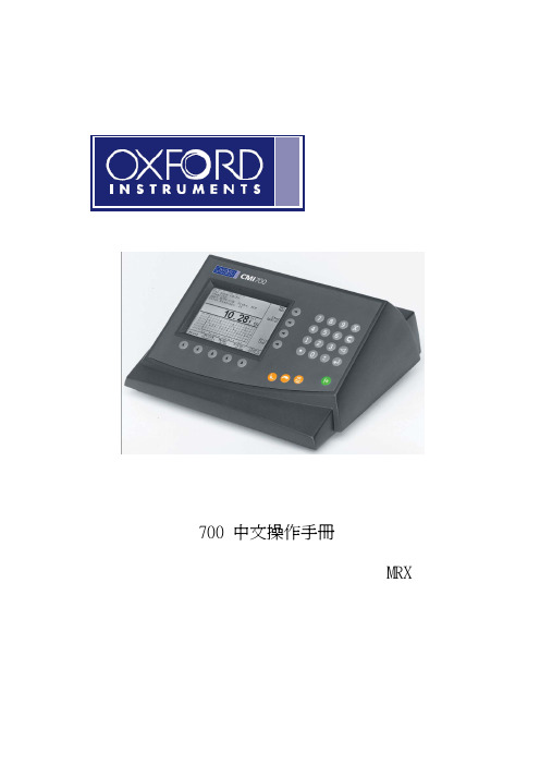
FE700测深仪中文说明书
700繁体中文手册MRX-CT
Copy To Cal Number: Range:1 to100
選擇所要複製到的位置 輸入完成按
Calibration Name For Current:xx Or Enter New Name:
輸入新名稱完成按
Calibration Identity For Current:xx Or Enter New Name:
Print List
Page Eject
△
△
△
△
△
8
△
△
△
1
****
***
面銅其他檔案延伸
Mon May 13, 2002 15 : 49 : 55
No.
Name
Identity Sort Name
△
CALIBRATION LIST
Main Menu
New
Edit
View
Print List
Page Eject
1
儀器說明
正面
7 4 1 .
8 5 2 0
9 6 3 ± C
m =
按鍵說明 確認 主選單或功能按鍵 退格 修改(單位,小數點位數等) 校正 m = 測量 手動測試或校正時測量 2 0-9
. C
清除(測試中最後一筆資料) 取消
數字 小數點
背面 MRX PROBES SRP TRP ETP EMX PROBES SMP ECP NIP
步驟8 是否輸入上限? 一般皆設定為:Off
6
Low Limit For Current:Off Or Select Number: 1:Off 2:On
步驟9 是否輸入下限? 一般皆設定為:Off
Measure Fine Lines For Current:Off Or Select Number: 1:Off 2:On
测深仪说明书
华测测深仪产品系列D330测深仪操作手册第一版上海华测导航技术有限公司二○一○年九月目录第一章测深仪的工作原理 (1)§1.1测深仪简介 (1)§1.2测深仪的技术原理 (1)§1.2.1回声测深的原理 (2)§1.2.2测深仪相关参数 (2)§1.3测深仪的相关名词 (4)§1.3.1水深数据分类 (4)§1.3.2数据格式 (4)§1.3.3测量周期设置 (5)§1.3.4声速设置 (6)§1.3.5吃水深度设置 (7)第二章D330测深仪 (8)§2.1性能指标及特点 (8)§2.2标准配置单 (10)§2.3安装连接图 (11)§2.4测深软件主界面 (12)§ 2.4.1主菜单 (12)§ 2.4.2快捷工具栏 (13)§ 2.4.3状态栏 (14)§ 2.4.4测量参数设置 (14)§ 2.4.5调用屏幕键盘 (15)§2.5操作步骤 (16)§ 2.5.1水深数据采集 (16)§ 2.5.2水深数据回放 (16)§ 2.5.3水深数据复制和备份 (17)第三章与GPS联机测量 (18)§3.1连接GPS (18)§ 3.1.1与GPS设备的连接安装 (18)§ 3.1.2连接安装的注意事项 (18)§3.2水上测量软件的设置 (19)§3.3升级和注册 (22)§ 3.3.1固件升级 (22)§ 3.3.2注册测深仪 (22)第四章其他相关操作 (28)§4.1触摸屏的校准 (28)§4.2整机的维护注意事项 (30)§ 4.2.1主机的维护 (30)§ 4.2.2换能器的维护 (30)§ 4.2.3换能器连接杆的维护 (31)§ 4.2.4安全注意事项 (33)附录联系方式 (34)第一章测深仪的工作原理第一章测深仪的工作原理§1.1测深仪简介首先感谢您选择了华测D330型测深仪,这里我们将向您介绍该仪器的性能、操作和使用要点,它对于您掌握和使用这台仪器会有一定的帮助,并通过您的熟练应用为您带来外业工作上的方便、快捷和理想的测量成果。
富罗诺 FE-700R 鱼雷探测仪产品说明书

s Cost-effective; No paper, noconsumables; high accuracy and high reliabilitys 6.5" color LCD display featuring awide viewing angle and adjustable brightnesss Viewing window 15 min wide onany range setting with 1 min time markss Choice of system frequency -high-resolution shallow depth sounding with a 200 kHz transducer or deep water sounding with a 50 kHz transducers Various modes for experiencedusers with never-get-lost default positions Compact display cabinetenabling installation at a conning position or any other convenient locations Depth data for last 24 hours inmemory to play back the past sounding informations Digital interface for radar, VDR,ECDIS, and other navigational or radiocommunication equipment s Meets IMO standards MSC.74(69)Annex 4Model FE-700The future today with FURUNO's electronics technology.FURUNO ELECTRIC CO., LTD.9-52 Ashihara-cho, Nishinomiya City, Japan Telephone: +81 (0)798 65-2111Telefax: +81 (0)798 65-4200, 66-4622, 66-4623TRADE MARK REGISTERED MARCA REGISTRADACatalogue No. E-380aEconomical, new standard of echo-sounding equipmentNAVIGATIONAL ECHO SOUNDERThe FE-700 is a result of 50 years of Furuno's vast range of experience and advanced microelectronics technology fields in developing echo sounders, sonars, and underwater application equipment and systems. This echo sounder is a breakthrough over the conventional paper eating sounders; there are no consumable items. The purpose of the echo sounder is to provide safe navigation by detecting the clearance below the ship (particularly in shallow waters) as required on the SOLAS Convention ships by the new IMO standards.The basic system consists of a display unit, a distribution box, a matching box, and a transducer. The 6.5" high-brightness TFT color LCD display offers an easy-to-read depth sounding in various modes, permitting optimum representation with respect to the environment.Detection range is automatically varied but there is manual override to select the required scale. The displayed record is visible for 15 min on any range and an instantaneous sounding is directly shown in large numerals in addition to the graphical display.Depths, associated time, and position are stored for 24 h in memory. The data can be played back at any time.Visual and audible alarms are generated when the water depth below transducer is shallower than a user-preset depth. When the seabed is lost because of the lowered detection or out of range setting, the alarm comes on. The receiver sensitivity is automatically controlled with the tracking depth; manual override is possible to improve the detection and to reduce the surface clutter.The transducer is available in 200 kHz or 50 kHz. The 200 kHz system is advantageous in rough weather or congested waterways in shallow waters whereas the 50 kHz system is recommended for deeper range operation. Depth data can be output in IEC 61162 format to radar, ECDIS, VDR (Voyage Data Recorder), and other radiocommunication and navigation equipment. Optional software is available to transfer the sounding data to a personal computer.Clear depth reading on bright Color LCD DisplayDBS ModeHISTORY ModeThis mode provides a mix of Contour and Strata displays.The Contour display can be shifted back to the past over 24 h while the right side Strata display (layers of different colors according to reverberationstrengths) shows the latest five minutes of sounding data.Selector displays the logging on depths and own ship positions with associated time. You can select the time intervals among 5 s, 1 and 2 min options on the Menu.The log book contains 60pages that can bescrolled up or down with [+] or [-] key. Entry to the logbook is every 5 s over 24 h.Depth Below Surface mode provides a draft-adjusted depth reading and is useful in referencing to the nautical chart. The draft is adjustable with the [DRAFT] key at the DBS position of the Mode Selector. If you find any difficulty to check for the draft value,use the NAV mode, where you can find the bottom clearance under the keel.200 kHz200 kHz Strata color display many bubbles or wakes of other vessels. It is suitable in most echo sounding applications in shallow waters on the continental shelf.50 kHz(Echogram from a sister version fish finder working1.DisplayGraphical display on 6.5" color LCD,8 colors or 8 level monochrome,320 X 234 pixelsDisplay window for 15 min, assured on all ranges. Depth, position and associated time stored every 5 s for 24 h. Play back at interval of 5 s, 1 or 2 min.2.Display Modes Nav, History, DBS, Logbook, OS Data, etc.3.Frequency 50 or 200 kHz4.Output Power 600 W rms5.Range Scale 5, 10, 20, 40, 100, 200, 400, 800 m(May be selected for feet or fathoms)6.Accuracy ±2.5 % on any range7.Minimum Range 1.2 m (200 kHz), 2.0 m (50 kHz)8.Discrimination 5.8 mm per meter depth on 20 m range,0.58 mm on 200 m range9.Pulse Repetition Rate (PRR)Depth (m)P/L (ms)PRR (pulses/minute)5, 100.25750200.25750400.38375100 1.00150200 2.0075400, 800 3.604210.Picture AdvanceRange (m)Display window (minute)5, 10, 20 1.8/1540,1008/1520020400, 8003011.Interface (IEC 61162-1)Inputs:RMA, RMC, GLL, VTG, ZDA, GGA Outputs:SDDPT, SDDBT 12.AlarmsAudio-visual alarms for shallow water, lost bottom and power failure13.TransducerType and Beamwidth 50B-6B:28°, 200B-8B: 5.4°14.Power Supply24 VDC, 20 W, 115/230 VAC, 20 VA 15.Environmental ConditionsTemperature: -15°C to +55°C (IEC 60945)Waterproofing:Display unit: IPX5 (IEC 60529) and CFR46 (USCG)Distribution box, Matching box: IPX2EQUIPMENT LIST Standard1.Display unit FE-701 1 unit2.DIstribution box FE-702 1 unit3.Matching box MB-502 (for 50B-6), MB-504 (for 200B-8) 1 unit4.Transducer with 15 m cable 1 unit5.Transducer Tank TTF-5600 (for Xdr 50B-6B), TTF-2000 (for Xdr 200B-8B)20 mmT standard, 12/25 mmT optional 1 unit Options1.Transducer switch box EX-82.Digital depth indicator FE-7203.Dimmer controller for FE-7204.Junction box JIS F8821-15.Software for PC, 02-522-9900002XB Printed in JapanFURUNO U.S.A., INC.Camas, Washington, U.S.A.Phone: +1 360-834-9300 Telefax: +1 360-834-9400FURUNO (UK) LIMITEDDenmead, Hampshire, U.K.Phone: +44 2392-230303 Telefax: +44 2392-230101FURUNO FRANCE S.A.Bordeaux-Mérignac, FrancePhone: +33 5 56 13 48 00 Telefax: +33 5 56 13 48 01FURUNO ESPANA S.A.Madrid, SpainPhone: +34 91-725-90-88 Telefax: +34 91-725-98-97FURUNO DANMARK ASHvidovre, DenmarkPhone: +45 36 77 45 00 Telefax: +45 36 77 45 01FURUNO NORGE A/SÅlesund, NorwayPhone: +47 70 102950 Telefax: +47 70 127021FURUNO SVERIGE AB Västra Frölunda, SwedenPhone: +46 31-7098940 Telefax: +46 31-497093FURUNO SUOMI OYHelsinki, FinlandPhone: +358 9 341 7570 Telefax: +358 9 3417 5716SPECIFICATIONS SUBJECT TO CHANGE WITHOUT NOTICE344 13.5"315 12.4"300 11.8"236 9.3"200 7.9"100 3.9"4- 7200.8"190.8"Distribution Box Weight 6 kg, 13.2 lb。
tSH-700 系列繁體中文使用手冊说明书

tSH-700系列繁體中文使用手冊精簡型序列埠分享器 2020年6月 版本: 1.8:目錄檢查配件 (4)更多資訊 (4)1.產品介紹 (5)1.1選型指南 (7)1.2規格 (8)1.3配置圖 (9)1.4機構圖 (11)1.4.1tSH-700 系列模組 (11)1.4.2CA-002 DC 電源線 (12)1.5腳位定義 (13)2.啟動 TSH-700 模組 (14)步驟1:連接電源和電腦主機 (14)步驟2:連接M ASTER和S LAVE設備 (16)步驟3:安裝軟體到您的電腦 (17)步驟4:配置正確的網路設定 (17)步驟5:配置A PPLICATION M ODE (19)步驟6:配置序列埠設定 (20)步驟7:測試您的T SH-700模組 (21)3.配置網頁 (23)3.1登入 T SH-700網頁伺服器 (23)3.2H OME首頁 (25)3.3A PPLICATION M ODE (26)3.3.1Converter Application (tSH-72x 系列) (26)3.3.2Sharer Application (tSH-73x 系列) (29)3.4S ERIAL P ORT 配置 (32)3.4.1Port1 Settings (32)3.5N ETWORK S ETTING配置頁 (34)3.5.1IP Address Settings (34)3.5.2General Settings (36)3.5.3Restore Factory Defaults (38)3.5.4Firmware Update (40)3.6F ILTER配置頁 (41)3.6.1 Accessible IP (filter is disabled when all zero) .......................................................................................... 41 3.7 M ONITOR 配置頁 .............................................................................................................................................. 42 3.8 C HANGE P ASSWORD 配置頁 ............................................................................................................................... 43 3.9L OGOUT 配置頁 (43)附錄 A: 疑難排解 ....................................................................................................................................................... 44 如何恢復模組原廠預設的網頁伺服器登入密碼? ...................................................................................................... 44 附錄 B: 應用注意 ....................................................................................................................................................... 46 如何設定 T IMEOUT 值? ................................................................................................................................................... 46 附錄 C: 手冊修訂記錄 (48)檢查配件產品包裝內應包含下列配件:更多資訊相關文件位置 :https:///en/download/index.php?nation=US&kind1=&model=&kw=tSHFirmware位置 :/en/download/show.php?num=1519&nation=US&kind1=&model=&k w=tSH相關軟體位置 :https:///en/download/index.php?nation=US&kind1=&model=&kw=eSearch1.產品介紹泓格推出一系列tGW-700/tDS-700精簡型模組後,受到熱烈回響,因此繼續以研發、創新的精神,來擴展模組新功能以滿足使用者的各項應用需求。
气体检测仪700系列说明书

DescriptionModel 700 Series Sensors are a non-intrusive “Smart” sensors designed to detect and monitor oxygen and Toxic Gases in air using electrochemical sensor technology.The intelligent plug-in, field replaceable cell provides automatic recognition of gas type and range, and features over-sized gold-plated connections that help prevent corrosion.The Model 700’s rugged framework includes an intrinsically safe electro-polished 316 stainless steel housing with fully encapsulated electronics and dual layer surge protection.This innovative design virtually eliminates sensor failure due to water in-gress, corrosion, vibration, and transient spikes.A primary feature of the Model 700 is embedded intuitive software that simplifies operator interface by guiding the user through routinecalibration, configuration, and fault diagnostic functions using a built-in alpha/numeric display.The Model 700 is equipped with standard analog 4-20mA, and Modbus™ RS-485 outputs. Among its unique features is a wireless option that can be used with Detcon’s SmartWireless® product line. Additional integration options include a Remote Alarm Module (RAM) and HART.Detcon’s toxic gas and oxygen sensors have a long shelf life and are sup-ported by an industry-leading warranty.Model DM 700Toxic gas sensorsFeaturesFailsafe User-Friendly Interface• LED Display (With Antiglare Cover)• Full Text Display Method • Non-intrusive Interface • Auto Zero/Auto Span• Pre-emptive Fault DiagnosticsEnvironmentally Bulletproof• Electropolished 316SS Construction • 100% Epoxy Encapsulated Circuitry • Bulletproof I/O Protection• Water-proof, Corrosion-Proof, Vibration-ProofModular and Serviceable • Modular Design• Plug and Play Components• Quick Thread Release Sensor Endcap (Allen Wrench only required)• Integral Calibration PortApplications• Oil & Gas• Chemical Plants • Food & Beverage • Steel Mills • Pulp and Paper • Refineries• Wastewater Treatment Plants •Utilities(shown as PN 967-505094-100 in SS junction box)Gas Part Number Warranty Measuring Accuracy Response Time Operating Temp Storage Temp Operating Humidity Acetylene (*See Note)967-12EG91-100 2 years0-100 ppm±2% FS T90≤140 seconds-4 to 122ºF/-20 to 50ºC-31 to 131ºF/-35 to 55ºC15-90% RH non-condensing Ammonia967-505091-100 2 years0-100 ppm±2% FS T90≤90 seconds-40 to 122ºF/-40 to 50ºC-31 to 131ºF/-35 to 55ºC15-90% RH non-condensing Arsine967-191991-001 1.5 years0-1 ppm±2% FS T90≤60 seconds-4 to 104ºF/-20 to 40ºC-31 to 131ºF/-35 to 55ºC20-95% RH non-condensing Bromine967-747591-005 2 years0-5 ppm±2% FS T90≤60 seconds-4 to 122ºF/-20 to 50ºC-31 to 131ºF/-35 to 55ºC15-95% RH non-condensing Butadiene967-12EB91-100 2 years0-100 ppm±2% FS T90≤140 seconds-4 to 122ºF/-20 to 50ºC-31 to 131ºF/-35 to 55ºC15-90% RH non-condensingCarbon Monoxide967-444491-100 3 years0-100 ppm±2% FS T50≤10 sec./T90≤30 sec.-40 to 122ºF/-40 to 50ºC-31 to 131ºF/-35 to 55ºC15-90% RH non-condensingChlorine967-747491-010 2 years0-10 ppm±2% FS T90≤60 seconds-4 to 122ºF/-20 to 50ºC-31 to 131ºF/-35 to 55ºC15-90% RH non-condensing Chlorine Dioxide 700967-747691-050 2 years0-50 ppm±2% FS T90≤120 seconds-4 to 104ºF/-20 to 40ºC-31 to 131ºF/-35 to 55ºC10-95% RH non-condensing Chlorine Dioxide 701967-777791-001 2 years0-1 ppm±2% FS T90≤60 seconds-4 to 104ºF/-20 to 40ºC-31 to 131ºF/-35 to 55ºC15-90% RH non-condensing Diborane967-192191-005 1.5 years0-5 ppm±2% FS T90≤60 seconds-4 to 104ºF/-20 to 40ºC-31 to 131ºF/-35 to 55ºC20-95% RH non-condensing Ethanol967-12EO91-100 2 years0-100 ppm±2% FS T90≤140 seconds-4 to 122ºF/-20 to 50ºC-31 to 131ºF/-35 to 55ºC15-90% RH non-condensing Ethylene (*See Note 2)967-12ED91-100 2 years0-100 ppm±2% FS T90≤140 seconds-4 to 122ºF/-20 to 50ºC-31 to 131ºF/-35 to 55ºC15-90% RH non-condensing Ethylene Oxide967-12EJ91-100 2 years0-100 ppm±2% FS T90≤140 seconds-4 to 122ºF/-20 to 50ºC-31 to 131ºF/-35 to 55ºC15-90% RH non-condensing Fluorine967-272791-001 1.5 years0-1 ppm±2% FS T90≤80 seconds14 to 104ºF/-10 to 40ºC-31 to 131ºF/-35 to 55ºC10-95% RH non-condensing Formaldehyde967-12EP91-100 2 years0-100 ppm±2% FS T90≤140 seconds-4 to 122ºF/-20 to 50ºC-31 to 131ºF/-35 to 55ºC15-90% RH non-condensing Germane967-232591-002 1.5 years0-2 ppm±2% FS T90≤60 seconds-4 to 104ºF/-20 to 40ºC-31 to 131ºF/-35 to 55ºC20-95% RH non-condensing Hydrogen (1%)967-070791-01P 2 years0-1%volume±2% FS T90≤60 seconds-40 to 104ºF/-40 to 40ºC-31 to 131ºF/-35 to 55ºC5-90% RH non-condensing Hydrogen (4%)967-050591-04P 2 years0-4%±2% FS T90≤60 seconds-40 to 104ºF/-40 to 40ºC-31 to 131ºF/-35 to 55ºC5-95% RH non-condensing Hydrogen PPM967-848491-100 2 years0-100 ppm±2% FS T90≤30 seconds-4 to 122ºF/-20 to 50ºC-31 to 131ºF/-35 to 55ºC15-90% RH non-condensing Hydrogen Bromide967-090891-030 1.5 years0-30 ppm±2% FS T90≤70 seconds-4 to 104ºF/-20 to 40ºC-31 to 131ºF/-35 to 55ºC10-95% RH non-condensing Hydrogen Chloride967-090991-030 1.5 years0-30 ppm±2% FS T90≤70 seconds-4 to 104ºF/-20 to 40ºC-31 to 131ºF/-35 to 55ºC10-95% RH non-condensing Hydrogen Cyanide967-131391-030 2 years0-30 ppm±2% FS T90≤40 seconds-40 to 104ºF/-40 to 40ºC-31 to 131ºF/-35 to 55ºC5-95% RH non-condensing Hydrogen Fluoride967-333391-010 1.5 years0-10 ppm±2% FS T90≤90 seconds-4 to 95ºF/-20 to 35ºC-31 to 131ºF/-35 to 55ºC10-80% RH non-condensingHydrogen Sulfide967-242491-100 2 years0-100 ppm±2% FS T50≤10 sec./T80≤30 sec.-40 to 122ºF/-40 to 50ºC-31 to 131ºF/-35 to 55ºC5-90% RH non-condensingHydrogen Sulfide (DC)*967-303091-1002 years0-100 ppm±10%applied gasconcentrationor ±3 ppm,whichever isgreaterT20 ≤ 20sec-40 to +131°F/-40 to +55°C -31 to +131°F/-35 to +55°C5-90% RH non-condensing 967-303091-050T50 ≤ 45 sec967-303091-025 T90 ≤ 60 secMethanol967-12EE91-100 2 years0-100 ppm±2% FS T90≤140 seconds-4 to 122ºF/-20 to 50ºC-31 to +131ºF/-35 to 55ºC15-90% RH non-condensing Methyl Mercaptan967-12EK91-100 2 years0-100 ppm±2% FS T90≤45 seconds-40 to 122ºF/-40 to 50ºC-31 to +131ºF/-35 to 55ºC15-90% RH non-condensing Nitric Oxide967-949491-100 3 years0-100 ppm±2% FS T90≤10 seconds-4 to 122ºF/-20 to 50ºC-31 to +131ºF/-35 to 55ºC15-90% RH non-condensing Nitrogen Dioxide967-646491-010 2 years0-10 ppm±2% FS T90≤40 seconds-4 to 122ºF/-20 to 50ºC-31 to +131ºF/-35 to 55ºC15-90% RH non-condensingOxygen967-341520-025 2 years 0-25%volume±1% FS T90≤10 seconds-4 to 122ºF/-20 to 50ºC-40 to 122ºF/ -40 to 50ºC15-90% RH non-condensingOzone967-393991-001 2 years0-1 ppm±2% FS T90≤120 seconds14 to 104ºF/-10 to 40ºC-31 to +131ºF/ -35 to 55ºC10-95% RH non-condensing Phosphine967-192091-005 1.5 years0-5 ppm±2% FS T90≤30 seconds-4 to 104ºF/-20 to 40ºC-31 to +131ºF/ -35 to +55ºC20-95% RH non-condensing Silane967-232391-050 1.5 years0-50 ppm±2% FS T90≤60 seconds-4 to 104ºF/-20 to 40ºC-31 to 131ºF/ -35 to +55ºC20-95% RH non-condensing Sulfur Dioxide967-555591-020 2 years0-20 ppm±2% FS T90≤20 seconds-4 to 122ºF/-20 to 50ºC-31 to +131ºF/ -35 to +55ºC15-90% RH non-condensing *Note: Acetylene can only be used with a Group A enclosure.*Note2: This product is a safety device to detect hazardous conditions, and is not intended for process control application in fruit ripening operations.*Note3: DC=Desert Climate Sensors are 3rd-party test report to ISA 92.00.01 2010 standardSystem specifications Sensor TypeContinuous diffusion/adsorption3-electrode electrochemical cellPlug-in field replaceable Intelligent Type OutputsLinear 4-20 mA DCRS-485 MODBUS-RTUElectrical ClassificationExplosion proofC CSAUSClass I, Division 1, Groups B, C, D ()Class I, Zone 1, Group IICATEXII 2 G Ex d ib IIB + H2 T4 GBIngress ProtectionNEMA 4X, IP66Safety ApprovalscCSAusATEXCE MarkingSIL2 Certified to IEC 61508* Specifications subject to change without noticeOrder guidePN 967 - _ _ _ 090 - _ _ z DM - 700 Sensor Assembly (no junction box) PN 967 - _ _ _ 091 - _ _ z DM - 700 Sensor Assembly with Aluminum J-Box PN 967 - _ _ _ 094 - _ _ z DM - 700 Sensor Assembly with 316 SS J-Box _ = Any character as shown in table on prior pagez = Code for Regulatory Approval Required, C for CSA or A for ATEX, others available.C for CSA or A for ATEX Mechanical specificationsDimensions7”H x 2.2” Dia.; 178mmH x 65mm Dia. (sensor assembly only)11”H x 6.1”W x 3.75”D; 280mmH x 155mmW x 96mmD (with junction box) Mounting holes (J-box) 5.5”; 140mm center to centerWeight2 lbs; 0.907kg (sensor only)6 lbs; 2.72kg (w/aluminum j-box)9 lbs; 4.08kg (w/stainless steel j-box)Electrical specificationsPower Input11 - 30 VDCPower ConsumptionNormal operation = 30mA @ 24V (<0.75 watt)Maximum = 50mA @ 24V (1.2 watts)Inrush Current500mA @ 24V (typical)RFI/EMI ProtectionComplies with EN50270Analog OutputLinear 4-20mA DC (1,000 ohms max loop load @ 24VDC)0mA All Fault Diagnostics2mA In-Calibration4-20mA 0-100% full-scale22mA Over-range conditionSerial RS-485 OutputRS-485 Modbus™ RTUBaud Rate9600 BPS (9600, N, 8, 1 Half Duplex)Status Indicators4-digit LED display with gas concentrationFull-script menu prompts for AutoSpan,Set-up Options, and Fault ReportingFaults MonitoredLoop, Input Voltage,Missing Sensor, Zero,Processor, Memory, CalibrationCable RequirementsPower/Analog3-wire shielded cableMaximum distance is 13,300 feet with 14 AWGSerial Output2-wire twisted-pair with ground, shielded communicationcable specifically for use with RS-485 installationsMaximum distance is 4,000 feet to last sensorI/O ProtectionOver -voltage, Miswiring, EMI/RFI ImmunityIntegration optionsThe first three characters of the PN define the Integration options as follows:PN 9R7 - Remote Alarm Module (Remote Operation and 2 Alarm Relays plus Fault)PN 9H7- Hart Integration Module (Hart Communication Protocol version 7.0, HART Registered)PN 9K7- Combination HART / Remote Alarm Module (Combines the features of both into one module)Copyright © 2020 Teledyne Technologies. All rights reserved. **********************************************AMERICAS4055 Technology Forest Blvd.The Woodlands, TX 77381USATel.: +1 713-559-9200Fax: +1 713-893-6729EMEAZI Est, Rue Orfila,CS 2041762027 ARRAS CEDEX, France Tel.: +33-3-21-60-80-80Fax: +33-3-21-60-80-00ASIA PACIFIC290 Guiqiao RoadPudong, Shanghai 201206People's Republic of China Tel.: +86-21-3127-6373Fax: +86-21-3127-6365Teledyne Gas & Flame Detection quality assurance programmes demand the continuous assessment and improvement of all our products. Information in this leaflet could thus change without notification and does not constitute a product specification. For more informa-tion, please contact us or your company representative。
FE-700导航回波测深仪中文操作说明

i
ii
目录
前言 ....................................................... iv
尊敬的 FE-700 用户:..................................iv 产品特性 ........................................................iv
英尺
15 30 60 120 300 600
英寻
3
5 10 20 50 100
* 默认设置;可自定义在不含量程 3 和 6 时使用。
1.5 精度
任何量程均为 ±2.5%
1.6 最小量程
0.5 米 (200 kHz),2.0 米 (50 kHz)
1.7 吃水
0 到 30 米,步距 0.1 米,默认值为 0 米
2.1 发射频率
50 kHz 或 200 kHz
3 系统菜单 ......................................... 11
3.1 系统菜单 ............................................... 11
3.2 系统菜单 1 ........................................... 12 3.3 系统菜单 2 ........................................... 12 3.4 系统菜单 3 ........................................... 13
重要注意事项
・ 本手册专为具有良好中文知识的读者而编写。 ・ 未经书面许可,不得复制或转载本手册的任何内容。 ・ 如果本手册丢失或破损,请联系经销商更换。 ・ 本手册内容和设备规格如有更改,恕不另行通知。 ・ 请将本手册置于方便之处,以便日后参考。 ・ 对因使用不当、被非授权代理或第三方改装设备(含软件)所造成的损害,FURUNO 概不负责。 ・ 丢弃本产品时须遵从当地工业废品处理规范。如在美国处理,请参照电子工业联盟规范
测深仪使用说明
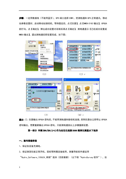
步骤:一定用数据线(不能用蓝牙),GPS端口选择COM1,把测地通和GPS正常通讯,移动站参数设置好,启动移动站接收机,等待固定后,点【仪器】,点【NMEA 0183输出】,GPGGA 前打勾,点【确定】,弹出成功设置对话框后再点【确定】,测地通显示【已经成功设置成NMEA输出】,退出测地通后即设置完成。
如下图:提示:①、仪器输出GPGGA语句后,不能用测地通和接收机连接,否则仪器会立即停止GPGGA 语句输出,想要重新输出GPGGA语句,只能测地通按以上步骤重新设置。
第一部分华测X90/X91(1+1)作为定位仪连接D330测深仪测量水下地形一、室内准备阶段1、保证各设备充满电。
2、保证测深仪能正常开机,鼠标等附属设备能用,测量导航软件建议用“Hydro_Software_100624_单频”版本(目前最新)(以下称“HydroSurvey软件”),该注册的地方提前注册好(HydroSounder软件和HydroSurvey软件),数据通讯测试好,如:GPS数据可输入HydroSurvey软件、HydroSounder软件可测水深(若测试,要插换能器且换能器一定要放水里,以防打坏换能器或损坏工控机)、水深数据可输入HydroSurvey软件。
3、保证GPS搜星、固定正常,输出GPGGA格式正常,注册正常。
4、控制点或参数找好,若需要做背景图提前做好。
二、外业准备阶段1、正常架设RTK(1+1),正常固定后去做点校正(同陆地操作一样)。
注:如果在同一个工地多次架站,注意HydroSurvey软件没有“重设当地坐标”功能,所以第二次、第三次。
架站,一定架设在已知点或每次都重新做点校正。
2、上船安装好换能器,保证换能器吃水深浅合适,固定换能器连接杆子时保证杆子垂直于水平面,保证杆子上下固定、前后固定、左右固定,连接好测深仪各设备后,测深仪开机。
注:换能器建议安装在中间靠船头方向一点的地方(船头上下跳动较大,船尾发动机、螺旋桨容易产生杂波),吃水可米不等,一般湖泊、河流吃水小一点,海洋测量吃水深一点,一般米(吃水太浅容易产生气泡,吃水太深,岸边测量容易换能器搁浅)。
TRACE 700用户手册说明书
Using templatesTemplates are intended to help simplify and speed up theprocess of entering and changing room information. They arebased on the idea that several pieces of information are commonfor many, if not all, of the rooms or types of rooms in a building.Examples of this type of similar information include designthermostat setpoints, wall/roof/floor construction types, amountand type of lighting, and so on. Templates are similar to theconcept of Master Cards in TRACE/Load Design600.The templates were designed for use in conjunction with theCreate Rooms – Single Sheet tab to allow the user to enterroom information on one screen. This allows much quicker entryof room data. In addition, because the user does not need torepeatedly select construction types, densities, and so on,templates reduce the chances of input errors. Finally, templatesalso make changes to files, and comparisons betweenalternatives, much easier.There are five types of templates. However, the Room templateacts as a super template. It does not contain any specific roomdata, but it allows grouping of the other four templates listedbelow:■Internal Load template■Airflow template■Thermostat template■Construction templateTemplates are generally created for each type of room in abuilding—office areas, conference rooms, hallways, rest rooms,and so on. After the templates have been set up, they areapplied, as appropriate, to the individual rooms in the CreateRooms section. The templates will bring in values that would betypical for the room type being entered in Create Rooms, andallow the user to override these inputs with any atypical valuesfor that specific room.In the following scenario, a set of templates for the office areas of a building will be created and applied in Create Rooms.1The first step in using templates is to create the templates. Click Create T emplates —TRACE 700 will open to the Room template.Note: It is much easier to create templates before the rooms have been input. Applying templates after the rooms have been input is time consuming and often difficult to do. Refer to Additional Items in this section for instructions on reverting inputs to templated values.2No templates have been input into this file.Therefore, the Internal Load tab should be selected.3From the Internal Load tab, the generalcharacteristics of theoffice areas’ internal loads will be input. Click New and enter Office Areas into the Description field. Enter the appropriate T ype , Density , Loads , and Schedule for the people. Repeat this for Lighting andMiscellaneous loads .Note: The internal load schedules typically should not use the schedule Available 100% or any schedule where the heating-design day type is greater than zero. This will cause TRACE 700 to take credit for internal loads during the heating-designcalculation. For additional details on schedules, refer to “Creating schedules” on page 6–120.4With the generalcharacteristics for theoffice areas’ internal loads defined, select theAirflow tab. Here, thegeneral characteristics ofthe office areas’ airflowswill be input. Click Newand enter Office Areasinto the Description field.Input the appropriateT ype, airflow rate (if thedefault value needs to beadjusted), and Schedulefor the Ventilation.Repeat this for all relevant fields on the Airflowtemplate.5With the generalcharacteristics for theoffice areas’ airflowsdefined, select theThermostat tab. In thisscenario, all of the roomsin the building will beconditioned to the samethermostat setpoints,allowing a singleThermostat template tobe used for the entirebuilding. Click New andenter Building in theDescription field. Inputthe Cooling dry-bulbsetpoint, Heating dry-bulb setpoint, andRelative humidity. If thefile will be used for energy analysis, then the Cooling driftpoint and Heatingdriftpoint, or the Coolingthermostat schedule andHeating thermostatschedule, should be input as well.Note: In almost all cases, theAuxiliary supply and VAVminimum schedule should beleft at their default values. Also, the airflow schedules must not be internal load schedules orany schedule where theheating-design day type is zero.This will cause TRACE700 toneglect airflow loads during the heating-design calculation. For additional details on schedules, refer to “Creating schedules”on page 6–120.Note: Typically users need to either create their own Thermostat schedules orselect none and let theprogram use the driftpoints (Thermostat schedulesoverride the driftpoints and setpoints for energy analysis calculations). Also, the thermostat driftpoints activate whenever there are 5percent or less of the people in the space (determined from the people schedule on a room-by- room basis).6With the generalcharacteristics for thebuilding thermostatsetpoints defined, clickthe Construction tab. In this scenario, theenvelope components of the building will beconstant throughout thebuilding. Therefore, asingle Constructiontemplate can be used forthe entire building. ClickNew and enter Buildinginto the Description field.Next, select theappropriate Constructiontypes for the building,override U-factors andShading coefficients ifnecessary, and input theWall, floor-to- floor, andPlenum heights. If thebuilding does not containa certain constructiontype, use the defaultvalue. In this scenario, the building has noskylights—therefore, thedefault construction value will be used in thetemplate.7Finally, select the Room template so that theindividual templates canbe grouped together. Click New and enter OfficeAreas in the descriptionfield. Next, select theappropriate Internal Load, Airflow, Thermostat, and Construction templatesfor the room type.Note: Typically the wall height and floor-to-floor height will be the same value. Refer to onlineHelp for additional details.8Click Close T emplates and click Create Rooms.To start inputting theroom data, give the rooma name (Office 101, in thiscase). For the Roomtemplate, select OfficeAreas.9The user now needs to input the appropriateroom-specific data (sizeof the space, walls,windows, roofs,partitions, and floors) and override any data fromthe templates that is notappropriate for the space.In this scenario, the roof,wall, glass, and floor area need to be input. TheSingle Sheet tab, pairedwith the data from thetemplates, can be used to input all of this data.Because this is the firstroom to be defined withthe templates, it is usually recommended that theindividual tabs be checked to verify the inputs for the space.10Now that Office 101 has been created, the otheroffices in the building can be modeled using thesame set of templates.Remember, templates for each type of room(offices, hallways,restrooms, and so forth)should be created, rather than one set of templates per room entered inCreate Rooms .In a typical TRACE700 file, templates for the other types of rooms (conference rooms, hallways, and so on) in the building would now be created.In this scenario, only offices will be modeled. A sample room will be input to show how to apply the templates. The room is 1,500ft2, has a flat roof, one east-facing exterior wall with 30percent glass, and is fairly typical of the other office spaces.Note: When the Roomtemplate is selected, manyof the values (such asInternal loads and Airflows)will populate based on theinputs from the InternalLoad, Airflow,Thermostat, andConstruction templates.Note: This building does not haveany skylights. Therefore, none willbe input in the Create Roomssection. This is the reason that theskylight glass type on theConstruction template could beleft at the default value.Additional items and notes1Any changes made to the template(s) will change the data in all of the rooms that use that template. Therefore, if the glass type specified in the project changes, all that the user needs to do is change the glass type in the Construction template(s) used by the rooms. If no templates were used in the file, then each wall would need to be manually changed to the new glass type. This is one of the ways that templates help save time.2When a templated value is overridden in Create Rooms, the color of the entry changes from red to black. It is important to understand this distinction. When you reapply or change anexisting template, only the values in red are affected. Entries in black must be changed manually or reverted back to thetemplated value.3To go back to an original template value, click *T emplate on the list for that parameter, or type in * and press enter for thenumeric fields.4Do not use any non-alphanumeric characters in the names of templates or rooms.5Create templates before creating rooms.6Project templates apply to only one file.7Global templates can be used in any number of files. They are created from the Library/Template Editors program. Globaltemplates are created in a very similar process and are usedwhen the same type of buildings will be modeled repeatedly.8 A Project template cannot be exported to a Global Template.9Create a Global template to make it available for any file, then add the Global Room (or individual) template into the Project.10When editing information, always check the upper left-hand corner of the screen to ensure that the correct alternative isbeing edited. Also verify that the correct template is being edited.11For additional details on how to use alternatives and templates, please refer to “Creating alternatives” on page6–114.12In Component T re e view, the user can press ALT+Z to revert the selected overridden value to a templated value quickly.Creating alternativesAlternatives can be created efficiently using three options:Use/Copy, Create based on, and Create new.■Use/Copy: Simulation will use data from another alternative,which minimizes calculation time and will not increase file size.Note: The Use/Copy option should only be applied to sections ofthe alternative where no changes will be made, because the userwill not be able to edit information in any section that uses datafrom another alternative.■Create based on: TRACE700 will create an editable copy ofinformation from another alternative, which will increase the filesize and the calculation time. However, the user can editinformation in any section that is created based on data from aprevious alternative. This option should be used when changesneed to be made to a section, but inputs similar to a previousalternative will be used.■Create new: TRACE700 will create a new section with no data, which will increase the file size and increase calculation time. Theuser can input completely new information in any section that isnew. This option should be used when changes need to be madeto a section or alternative, but inputs are not similar to the otheralternatives.Application considerations■The first step in creating alternatives is to determine how similar the existing alternative and the new alternative will be. In general,the more sections that use data from another alternative, thebetter. However, if changes need to be made to a portion of analternative, Create based on (if the alternatives are similar) orCreate new (if the alternatives are very dissimilar) should beused for the appropriate section(s). Two examples will be used toillustrate how to create alternatives in TRACE700:Multiple air-handlers served by a chiller plant vs. a large centralair-handler served by the same chiller plant,andA glass comparison.。
- 1、下载文档前请自行甄别文档内容的完整性,平台不提供额外的编辑、内容补充、找答案等附加服务。
- 2、"仅部分预览"的文档,不可在线预览部分如存在完整性等问题,可反馈申请退款(可完整预览的文档不适用该条件!)。
- 3、如文档侵犯您的权益,请联系客服反馈,我们会尽快为您处理(人工客服工作时间:9:00-18:30)。
6.1 检查 ............................. 19 6.2 清洁显示单元...................... 19 6.3 传感器维护........................ 19 6.4 更换保险丝和电池.................. 19 6.5 故障排除.......................... 20 6.6 诊断测试.......................... 21 6.7 测试图样 ......................... 21 6.8 清除存储器........................ 22
在试图操作和维护设备前,请仔细阅读并遵守该手 册中的安全信息和操作及维护说明。只有按正确的 程序进行操作和维护,才能确保该导航回波测深仪 发挥其优越的性能。
本设备由 FURUNO 电气有限公司设计、生产并 配备证明文件,并由英国劳氏船级社品质保证体系 证明符合 ISO 9001 标准。
产品特性
FURUNO FE-700 由显示单元和传感器单元构 成。回波测深数据会显示于高亮度的 6.5 英寸彩 色 TFT(薄膜晶体管)液晶显示屏上。
(/)。
i
ii
目录
前言........................................................ iv
尊敬的 FE-700 用户:.................. iv 产品特性 ............................. iv
4 回波质量设置................................... 14
4.1 演示显示.......................... 14 4.2 传感器设置........................ 14 4.3 水底回波电平...................... 15 4.4 TVG 级别.......................... 15 4.5 回波补偿.......................... 15
1.10 画面递进速度
慢速模式
15 分钟或更长
快速模式
画面递进距离
距离(米) 间隔(分钟)
5 10 20 40 100 200 400 800
1.8
8
20
30
SP - 1
E2366S01R 060111
FURUNO
FE-700
1.11 用户设置 1.12 自动设置模式 1.13 警报 1.14 Logbook 显示
7 菜单树 ............................................. 23
8 DIGITAL INTERFACE (IEC 61162-1 EDITION 2)...................................... 24
9 PARTS LOCATION. PARTS LIST.... 32 Declaration of Conformity
英尺 英寻
15 30 60 120 300 600 1500 2500
3
5 10 20 50 100 200 400
* 默认设置;第 3 和第 6 是必需的,其余 6 个量程可以自定义选用或屏蔽。
1.5 精度
任何量程均为 ±2.5%
1.6 最小量程
0.5 米 (200 kHz),2.0 米 (50 kHz)
v
FURUNO
FE-700
导航回波测深仪 FE-700 规格
1 显示单元
1.1 图形显示
6.5 英寸彩色 TFT 液晶显示器,320 x 234 像素
1.2 回波颜色
8 色或 8 个灰度的单色
1.3 显示区域
133 x 97 毫米
1.4 基本显示量程
单元
量程
1
2
3
4
5
6
7
8
米
5 10 20 40 100 200 400 800
增益、量程、警报、吃水、亮度、调光器、颜色、自动 增益、量程和杂波自动调整。 浅水位(默认 20 米)、水底丢失、电压下降 深度、内部时钟、L/L* 1 小时(间隔为 5 秒)、12 小时(间隔为 1 分钟)和 24 小时(间隔为 2 分钟) *: 需要外部导航传感器。
2 收发器特征(内置于显示单元)
“DBS”:水面以下深度的回波显示
“HISTRY”:深度的历史回波显示
“LOGBOOK”:带弹出表格显示的回波显示
按预设间隔记录的时间、深度和 L/L* 数据。
“OS DATA”:带弹出的表格显示的回波显示
导航数据;L/L*、航向*、航速*、时间、深度
“HELP”:带帮助菜单和注释的回波显示
“MENU”:带用户菜单的回波显示
1.1 控制按钮说明 ...................... 1 1.2 指示符与标记 ...................... 2 1.3 开启/关闭 ........................ 3 1.4 色调和亮度 ........................ 3 1.5 面板调光器 ........................ 3 1.6 显示模式 .......................... 4 1.7 量程刻度 .......................... 7 1.8 增益控制旋钮 ...................... 7 1.9 自动操作 .......................... 7 1.10 画面颜色 ........................ 7 1.11 浅水位警报 ....................... 8 1.12 吃水 ............................. 8
iii
前言
尊敬的 FE-700 用户:
感谢您购买导航回波测深仪。相信您一定会逐渐体 会到 FURUNO 品牌卓越的品质和可靠的性能。
50 年来,FURUNO 电气公司一直致力于开发和 制造船用电气设备,并以无与伦比的声誉成为该行 业的全球性旗舰。这是由于本公司拥有卓越的技术 和遍及全球的分销和服务网络。
SP - 2E2366S0来自R 060111FURUNO
FE-700
5.4 警报(深度、电源) 触点闭合信号,常开或常关,最大 250 VAC/ 200 VDC,3A。
6 电源
24 VDC (-10%, +30%):20W 或 100-115/200-230 VAC,单相,50/60 Hz 20VA。
4 传感器类型和波束宽度
4.1 50B-6B (50 kHz):
35°
4.2 200B-8B (200 kHz): 6°
5 接口 5.1 串行输入数据
5.2 串行输出数据
5.3 串行 I/O 数据 输出 输入
IEC61162-1,电流回路;1 个端口 RMA:L/L、对地速度、航迹 RMC:L/L(GPS)、对地速度、航迹、时间 GLL:L/L GGA:L/L VTG:对地速度,航迹(在菜单上选择真/磁) ZDA:时间 IEC61162-1,输出时段:1 秒;3 次输出/1 个端口 SDDPT:深度(米),吃水(米) SDDBT:传感器下深度(英尺、米、英寻) SDDBK:龙骨下深度(英尺、米、英寻) SDDBS:水面下深度(英尺、米、英寻) RS-232C,1 个端口 深度、时钟、L/L、船只的速度、航向 电脑的控制命令
Pub. No. OZS-23660-S1 DATE OF ISSUE: MAR. 2008
重要注意事项
・ 未经书面许可,不得复制或转载本手册的任何内容。 ・ 如果本手册丢失或破损,请联系经销商更换。 ・ 本手册内容和设备规格如有更改,恕不另行通知。 ・ 请将本手册置于方便之处,以便日后参考。 ・ 对因使用不当、被非授权代理或第三方改装设备(含软件)所造成的损害,FURUNO 概不负责。 ・ 丢弃本产品时须遵从当地工业废品处理规范。如在美国处理,请参照电子工业联盟规范
FE-700 规格 ..................................... SP-1
系统配置 ................................................. v
1 操作 ................................................... 1
2 菜单操作............................................ 9
2.1 菜单概述 .......................... 9 2.2 抑制低电平噪讯..................... 9 2.3 抑制干扰 .......................... 9 2.4 画面递进 ......................... 10 2.5 趋势 ............................. 10 2.6 间隔 ............................. 10
1.7 吃水
0 到 30 米,步距 0.1 米,默认值为 0 米
1.8 脉冲重复率 (PRR)
深度(米) P/L(毫秒) PRR(脉冲/分钟)
5, 10, 20
0.25
750
40
0.38
375
100
1.00
150
200
2.00
75
400, 800
3.60
42
1.9 显示模式
“NAV”:传感器(或龙骨)以下深度的基本回波显示