Behaviour based visual servo controller for satellite capture
基于单应性矩阵的移动机器人视觉伺服切换控制
基于单应性矩阵的移动机器人视觉伺服切换控制曹雨;刘山【摘要】For a monocular camera-based mobile robot system, a novel visual servo approach based on homography matrix is proposed. This approach realizes the control target by visual feedback with the lack of depth information, the robot can arrive at the position accurately by given an image taken under the position. Instead of common homography decomposition, this approach takes use of homography matrix elements to structure state varibles. In addition, considering the field of view constraint, the proposed approach doesn't need the reference target to be visible in real time by the transi-tivity of homography. A switched controller is designed to drive the robot to reach desired position under the satisfaction of the nonholonomic constraints. In this paper, theoretical analysis and simulation verify the feasibility and effectiveness of the approach.%针对具有单目视觉的移动机器人,本文提出了一种基于单应性矩阵的视觉伺服控制算法,在缺乏深度信息的情况下利用视觉反馈实现了移动机器人的控制目标,即给定机器人目标位姿下拍摄得到的图像,通过视觉伺服使机器人从初始位姿准确到达目标位姿.视觉反馈环节采用单应性矩阵中的元素构造状态变量,而非利用常见的单应性分解,此外,考虑到视野约束,本文提出的算法在计算单应性矩阵时结合了单应性的传递特性,从而避免了参考目标的实时可见性.伺服环节设计了切换控制器,在满足非完整约束的同时可驱动机器人到达期望位姿.理论分析及实物仿真验证了该算法的可行性和有效性.【期刊名称】《控制理论与应用》【年(卷),期】2017(034)001【总页数】11页(P109-119)【关键词】视觉伺服;移动机器人;单目视觉;单应性;视野约束;切换控制器【作者】曹雨;刘山【作者单位】浙江大学控制科学与工程学院,浙江杭州310027;浙江大学控制科学与工程学院,浙江杭州310027【正文语种】中文【中图分类】TP242视觉传感器在环境感知方面具有信息全面,可靠性高的优点,且成本低廉,故广泛应用于机器人系统中,在一定程度上能提高机器人的灵活性与智能性,因此视觉伺服控制在近些年得到了快速的发展.在近期的文献[1-4]中,国外的Chaumette以及国内的林靖、王麟琨等人就视觉伺服在机器人方面的应用分别从不同角度进行了综述.关于视觉伺服最新的一篇综述[5]则在视觉反馈与控制策略方面进行了更为详细的说明与分析.根据视觉反馈信息的类型,可将伺服控制系统主要分为基于位置的视觉伺服控制(position-based visual servoing,PBVS)和基于图像的视觉伺服(imagebased visual servoing,IBVS)两种方式[6].两种方式各有特点,前者适用于大范围的视觉导航,但是控制精度受系统参数影响较大,而后者更适用于小范围的精确定位,鲁棒性好.有学者提出了将两种方式相结合的混合视觉伺服控制(hybrid visual servoing, HVS)[7-8],即利用视觉得到的图像信息构造能部分反映机器人物理位姿的状态变量,作为系统的反馈信号,设计出合适的控制器对机器人的运动进行控制,最终达到伺服目标.该方法考虑了环境、系统鲁棒性等因素,兼具基于位置和图像两种方式的优点,实用性更强.传统的基于图像信息的视觉伺服一般是选取图像中的特征点并以其像素点坐标为控制变量,通过计算雅可比矩阵来设计控制器[1],不过这种方式往往存在图像局部遮挡以及噪声影响大的问题.因此为了提高系统鲁棒性,很多研究者用双视图几何关系代替传统的特征点作为反馈信号,如对极几何和单应性.文献[9]将对极几何与神经网络控制相结合,驱动非完整约束机器人到达指定位置并完成抓取.文献[10]在多机器人跟随实验中采用当前视图与相邻机器人视图之间的极点坐标作为视觉信号进而控制机器人运动,由于极点与相对位姿并非同构,极点为0只能保证共线,因此要求驱动机器人达到指定位姿时应注意引入其他判断条件.另外对极几何对于平面物体还存在病态的问题,以及当基线过短容易出现奇异现象.另一种几何关系单应性和对极几何一样表示的是两个视图之间的对应关系,不同之处在于单应性的描述对象限制为平面,且对应关系可唯一决定相对位姿,因此相比较于对极几何,单应性在视觉伺服中的应用更为广泛.在Malis等人提出了基于单应性矩阵分解的伺服策略[8]之后,后续有学者基于这种方式做了很多研究[11-13].不过由于单应性分解不具有唯一性,往往需要添加额外条件来进行判断.在Lopez提出了一种直接利用单应性矩阵元素进行视觉反馈控制的方法[14]之后,更多研究者选择避免使用单应性分解对系统进行控制[15-16].对于采用图像信息反馈的伺服系统而言,通常会存在视野约束问题,即如果期望图像中有一个参考物体,那么在机器人运行过程中需要实时能拍摄到该物体,一旦物体由于相机移动而超出了机器人视野范围,视觉反馈的信息将无法与期望图像相配对,进而导致控制器失效.针对视野约束问题,一种研究思路是通过路径规划,在满足视野约束的前提下设计出机器人最优移动路径[17-18],结合单应性反馈控制,通过设计单应性元素轨迹,利用轨迹跟踪的方式使机器人实现移动任务[19].另一种思路是结合主动视觉,采用云台扩大相机视野范围[20-21],极大地放松了机器人的物理移动约束,不过云台的使用相对于增加了机器人系统的自由度,对控制器的设计要求较高.本文针对具有单目视觉的移动机器人系统提出了一种基于单应性矩阵的视觉伺服控制算法,在缺乏深度信息的情况下利用视觉反馈实现移动机器人的控制目标.即给定期望位姿下拍摄的图像,利用当前图像与期望图像之间的单应性矩阵元素构造状态变量,设计切换控制器以及状态期望轨迹,将任务转化为轨迹跟踪问题,并结合机器人模型克服移动过程中的非完整约束.需要注意的是,在常规的伺服过程中当前图像与期望图像之间的单应性矩阵往往是通过特征点匹配进而计算得到,这种方式具有两个缺陷:第一是特征点匹配耗时较长,会延长系统的运行周期,容易导致系统不稳定;第二则是视野范围被局限,视野约束问题更明显,因为这种方式要求每一帧图像都要与期望图像有匹配点,这样极大地限制了机器人的移动范围,而且很容易出现无匹配点的情况,从而导致伺服失败.在本文中,视野约束可通过单应性的传递特性予以缓解,可以避免参考物体的实时可见性要求,一定程度上扩大了机器人的可移动范围,提高了系统的稳定性和有效性.文章其他部分组织如下:第2节对具有单目视觉的机器人系统进行了建模;第3节完成了切换控制器的设计;第4节给出了MATLAB仿真和实物仿真结果,验证了本文所提出算法的性能;最后一节为总结部分.2.1 运动学模型(Kinematic model)本研究的控制对象为具有单目视觉的移动机器人,如下图1所示,将单目相机固定在机器人上,相机坐标系Fc与机器人坐标系Fr重合,令v,ω分别表示机器人的线速度和角速度,vl,vr表示机器人左右轮线速度,有下式成立:如图2所示,在世界坐标系Fw下,机器人的位姿坐标为(x,z,θ),那么根据定义可描述该移动机器人运动学模型如下:2.2 视觉模型(Visual model)对于一系列共平面的点,在两个不同位姿下拍摄的图像具有一定的几何联系,这种几何转换关系则被称为单应性,表示该关系的矩阵即为单应性矩阵.如图3所示,在世界坐标系Fw下机器人的初始位姿坐标系和期望位姿坐标系分别为F和F∗,假设两者之间的旋转矩阵和平移向量为R,t,且满足下式成立:空间中存在一参考平面,其法向量已知,在期望坐标系F∗下表示为→n=[nxnynz]T,不失一般性,本文假定该参考平面正对于期望位姿,法向量为→n=[0 0 1]T.该平面上点在初始坐标系和期望坐标系下的空间坐标分别记为P和P∗,在图像坐标系中的投影分别为p和p∗,有下列关系式成立:其中:单应性矩阵,d为期望坐标系原点到参考平面的距离,未知常量,控制中可直接给定值,视为控制增益;K为机器人上单目相机的内参矩阵,定义为式中:fu,fv分别表示在像素坐标系单位方向上相机焦距所包含的像素数量,u0,v0表示像素坐标系中心的坐标.综合上述关系式,不难推导出图3所示模型中单应性矩阵为其中矩阵各元素分别为由上式可以看出,在实际运行中,图3所示模型的单应性矩阵的可用元素只有h11,h13,h31,h33,其余元素均为常量.利用这4个矩阵元素可构造出另外4个描述机器人位姿更为直观且具备物理意义的状态变量,分别为机器人的转角θ、横向偏差eh、纵向偏差ez与期望位置连线的夹角ψ,其中横、纵向偏差表示的是当前位置与期望位置连线分别在当前坐标系两坐标轴的投影与未知常量d的比值,反映了机器人的相对位姿.如图4所示,图中包含了机器人的当前坐标系和期望位姿坐标系,以及上文提到的具备物理意义的状态变量,各状态变量具体定义如下:上式ψ的定义中采用了双变量反正切函数和符号函数,具体定义如下:对式(7)求关于时间的导数,可得出系统状态与速度的关系考虑到移动机器人为两轮驱动,在运行过程需要由控制器不断输出两个轮子的线速度信号,故将式(9)与式(1)相结合:上式即为该机器人系统的相互作用关系式,也即本研究中的视觉模型.在上述模型基础上,机器人的期望位姿对应于该模型的一个期望的状态变量,使机器人移动到期望位姿的过程即等价于模型的状态变量收敛到期望状态变量的过程.设计整个视觉伺服系统控制流程如图5所示,主要运行步骤如下,首先给定期望图像,结合初始位姿所拍摄得到的当前图像判断具体属于哪种工作场景即初始位姿位于期望位姿的前方或后方,根据工作场景选择合适的控制器(A或者B),控制器的输出信号驱动机器人移动,根据实时拍摄得到的当前图像计算与期望图像之间的单应性进而得到当前状态,将当前状态作为控制器的输入信号完成整个控制闭环,进而完成控制目标.图5中控制器采用了一种切换控制策略,将控制过程分为3个步骤,如图6所示.其中:第1步是驱动机器人达到一个合适的偏转角;第2步机器人将移动至期望位姿的正后方或正前方(视工作场景而定),且保持朝向与期望位姿一致;第3步只需机器人直线移动到期望位姿即可.值得一提的是,文献[19-20]同样采用了将机器人运动过程转化为模型状态收敛到期望状态的过程,并且也是基于单应性矩阵获取系统状态.在文献[19]中,Lopez通过区分机器人相对期望位姿所处的工作空间,并与之对应地规划出3种移动路径,分别是SL(直线)、S-T(直线-t曲线)以及T1-T2(双t曲线),在确定移动路径后控制过程会分成若干个步骤,每个步骤都设置有子目标,即使单应性矩阵元素达到某设定值,从而最终驱动机器人完成任务.文献[20]提出的方法本质上与上述的SL类似,方勇纯通过利用主动视觉使得机器人在大多数工作空间都可实现SL移动路线.本文所提算法与上述不同之处在于,外设上仅通过一个单目相机进行信息获取,无附加自由度;控制变量由单应性矩阵多元素构造而成,并非单一的某个元素,相对而言鲁棒性更好;针对每个步骤均设计了期望轨迹,通过跟踪期望轨迹从而达到期望状态.下面将具体介绍. 3.1 当前状态获取(Derivation of current state)第2.2节中介绍了如何利用当前图像与期望图像之间的单应性矩阵元素构造系统状态变量,因此获取当前状态就是实时获取当前图像与期望图像之间的单应性矩阵.不同于引言中提到的常规单应性计算方法,本文是通过利用单应性传递特性的方式来计算单应性矩阵,该方法在一定程度上可以缓解视野约束.所谓传递特性即为:一个空间点在3个坐标系下的坐标分别为P1,P2,P3,由式(4)可知坐标满足P1 =H12P2,P2=H23P3,P1=H13P3,不难推出下式成立:H13=H12H23.注1 为方便起见,定义当前图像与期望图像之间单应性为Hct,初始图像与期望图像之间单应性为Hit,当前图像与初始图像之间单应性为Hci,i-initial,c-current,ttarget.因此Hct可数学表示为Hct=HciHit,而Hit可在一开始经由特征点匹配计算得到,如图7所示,令下标k表示第k帧图像,相邻两帧单应性为,那么将当前图像与初始图像之间的一系列相邻帧间单应性累乘即可得到Hci,进而得到实际需要的Hct.而相邻两帧的单应性由于两帧图像比较接近,故可以利用稀疏光流角点跟踪法[22]实现,可快速得到,从而缩短运行周期.另外,这种方法不需要期望图像中的参考物体实时在当前图像中,只要满足当前图像能实时捕捉到参考物体所在的平面即可.综上所述,利用这种方法获取当前状态既能够缩短运行周期,提高系统稳定性,又能在一定程度上放松视野约束,扩大机器人的可移动范围.3.2 控制律设计(Control law design)前文中提到两种工作场景,可根据初始图像与期望图像之间的单应性进行判断,其所对应的控制算法均根据运行时间分割为3步,每一步控制中机器人的实际移动轨迹取决于设计的期望轨迹,因此需要设计合适的期望轨迹使得机器人能够在运行过程中逐渐收敛到每一步控制的子目标,为方便讨论,这里笔者选择采用二次多项式的函数形式来描述期望轨迹,下面将具体介绍:a)初始位姿在期望位姿后面(z<0).步骤1 t∈[0,T1).设置时间点T1,使得机器人在[0,T1)时间段完成第1步的目标即到达一个合适的偏转角,若在初始位姿下满足eh·θ<0,说明机器人的偏转角已经达到后面步骤的要求,此时T1=0,否则T1/=0,需要运行第1步.选择前文构造的系统状态θ,eh,ez,ψ中的横向偏差eh和纵向偏差ez作为这一步的控制变量,由式(10)可得现给控制变量设计期望轨迹,使得在[0,T1)时间段内机器人移动能够让控制变量跟踪期望轨迹,设计轨迹如下:该期望轨迹表示在[0,T1)时间段内系统的控制变量eh,ez将收敛到,其中λ为设定常量正实数.设计控制律如下:其中为控制增益且为正实数.收敛性证明.将式(13)代入式(11)可得由于k1,k2为正实数,不难证明实际状态和期望状态的偏差满足指数衰减,从而说明实际状态逐渐收敛到期望状态.注2 后文控制律设计思路不做赘述.步骤2 t∈[T1,T3).设置时间点T3,这一步目标是让机器人在t∈[T1,T3)时间段移动到期望位姿正后方且朝向一致,选择eh,ψ作为控制变量,由于这个过程中ψ逐渐收敛到-π或π并非0,因此在控制算法中令ψ=ψ±π,使其与其他变量一样收敛到0,方便统一处理.由式(10)可得设计所要跟踪的期望轨迹与控制律如下:其中:k3为控制增益且为正实数;考虑到需要对矩阵M2求逆,因此在[T1,T3)时间段中选择一个中间时间点T2,使得ψ先收敛到0,再将eh收敛到0,避免在运行过程中出现M2奇异的现象.步骤3 t∈[T3,T4).设置时间点T4,这一步目标是让机器人在t∈[T3,T4)时间段沿直线移动到期望位姿,只需纵向偏差ez收敛到0即可,为了纠正可能由噪声引起的方向偏差,这里另外引入偏转角θ和纵向偏差ez一起作为控制变量,由式(10)可得设计所要跟踪的期望轨迹与控制律如下:其中k4为控制增益且为正实数.b)初始位姿在期望位姿前面(z≥0).步骤1 t∈[0,T1).设置时间点T1,这一步目标是让机器人在t∈[0,T1)时间段原地旋转至特定角度,使得纵向偏差ez=0,该特定角度θd(T1)可根据初始位置时的ψ(0)计算得到,设计轨迹使得在t∈[0,T1)时间内达到该角度,轨迹及控制律如下:其中k4为控制增益且为正实数,设置机器人线速度为0,只有角速度信号,有下式成立:结合式(19)-(20)完成第1步的控制,达到要求的偏转角.步骤2 t∈[T1,T3).设置时间点T3,这一步目标是让机器人在t∈[T1,T3)时间段移动到期望位姿正前方且朝向一致,选择ψ,θ作为控制变量,不同于场景(a),该场景下的ψ在该过程中逐渐收敛到0,无需进行处理.由式(10)可得设计所要跟踪的期望轨迹与控制律如下:与场景(a)中步骤2类似,为避免出现奇异的现象,考虑让ψ先收敛到0,再让θ收敛到0.这一步完成后机器人将到达期望位姿的正前方,接下来最后一步与场景(a)的最后一步完全一样,机器人将沿直线到达最终位姿.3.3 稳定性分析(Stability analysis)定理 1第3.2节设计的控制器可以使得机器人伺服系统的4个状态变量θ,eh,ez,ψ全部趋向0,也即证上述结论与机器人位姿偏差(x-xd,zzd,θ-θd)趋向0等价.故构造李雅普诺夫函数如下:其中i=1,2,3(xdi,zdi,θdi)表示步骤i的期望位姿,很显然,该函数为正定,接下来需要证明其导数为负定,以期望位姿坐标系为世界坐标系将工作空间分为4个象限,第一、二象限属于场景(b),第三、四象限属于场景(a),接下来就4个工作区域分别证明系统稳定性.第一象限:步骤1 ,根据控制律始终与ω异号或者都为0,故˙V≤0;步骤2根据控制律v≥0,ω≥0,θ≤0,其中等号不恒成立,可推出˙V≤0;步骤3,根据控制律≥0,v≤0,等号不恒成立,故˙V≤0.第二象限:步骤1,3与第一象限一致,不做赘述;步骤2根据控制律v≥0,ω≤0,θ≥0,其中等号不恒成立,可推出˙V≤0;第三象限:步骤1 (T1/=0)和步骤2:根据控制律,≤0,v≥0,θ≥0,且θ-θd和ω始终异号或都为0,其中等号不恒成立,故˙V≤0;步骤3 ,根据控制律,≤0,v≥0,等号不恒成立,故˙V≤0.第四象限:步骤1(T1/=0)和步骤2:根据控制律,≤0,v≥0,θ≤0,且θ-θd和ω始终异号或都为0,其中等号不恒成立,故˙V≤0;步骤3与第三象限一致,不赘述.综上所述,在整个工作空间,整个运行过程中,控制律始终保证李雅普诺夫函数导数˙V≤0,且等号不恒成立,因此该系统的是全局稳定的.为了验证本算法的可行性及有效性,本节提供了在MATLAB环境下的仿真结果,并且在此基础上利用机器人模拟软件v-rep模拟实际机器人系统,将算法在该实物模拟系统中进行测试,仿真和测试表明,本算法具有良好的性能,能有效完成视觉伺服任务.4.1 仿真(Simulation)在仿真中,设定期望位姿为(0,0,0),生成一个虚拟平面作为参考平面,再利用MATLAB 生成虚拟针孔相机作为传感器,用于检测特征点.仿真中针对两个工作场景下的参数略微有些不同,场景(a):T1=20 s(或0 s),T2=40 s,T3=50 s,T4=80 s, λ=0.5;场景(b):T1=10 s,T2=20 s,T3=50 s, T4=80 s,两个场景下的采样时间均为T=0.5 s,控制增益ki=1(i=1,2,3,4),且令未知量d=1.下面设置3个初始位姿来观察仿真效果,初始位姿分别为(-2,-4,0),(-1,-4,),(-2,2,0),图8给出了算法的仿真效果.图8中所示坐标系为期望位姿坐标系,期望位姿为原点,方向朝向z轴,箭头线表示机器人运行过程中的朝向.根据仿真结果所示,3个初始位姿下的移动机器人最终所到达的位姿坐标分别为(0,-0.0014,0),(0,-0.0013,0), (-0.0044,0,0),从最终到达的位姿以及上图中的移动路径曲线来看,本文所设计的视觉伺服算法能够驱动机器人渐近稳定地移动到期望位姿处.4.2 测试(Test)在基于MATLAB仿真的基础上,本文还基于机器人模拟平台v-rep对算法进行了模拟实物测试, v-rep(virtual robot experimentation platform),是一个非常先进的机器人及模拟自动化软件平台,它能让使用者模拟整个机器人系统或其子系统(如传感器或机械结构),通过详尽的应用程序接口(API),可以轻易的整合机器人的各项功能.因此基于该平台模拟的实验运行结果能够一定程度上逼近实际的实验结果,从而从实际的角度验证该算法的有效性.为了方便比较,测试环节本文将机器人初始位姿设定为与前文仿真一致的3个位姿分别为(-2,-4,0),(-1,-4,),(-2,2,0),期望位姿均为(0,0, 0),位姿对机器人系统为未知量.根据前文分析,这3个位姿分别对应两种工作场景,接下来分别介绍实验结果.场景(a):该工作场景下所对应控制器参数分别为采样时间T=0.5 s,T1=20 s(或0 s),T2=40 s, T3=50 s,T4=80 s,λ=0.5,控制增益k1=1.2, k2=1,k3=1.2,k4=1,未知量d=1.期望图像如图9所示.a)初始位姿(-2,-4,0).实验要求算法实现驱动机器人从初始位姿移动到拍摄出图9所示期望图像的位姿.图10是截取的机器人运行过程中反馈的实时图像,其中第一张和最后一张分别为初始图像和终止图像.可以看出在运行过程中期望图像中的参考物体并没有实时出现在当前图像中,当目标物体“消失”在视野内的时候伺服依然能够正常进行,说明本文提出的算法一定程度上放松了视野约束,避免了要求目标物体实时可见造成的机器人物理局限性.图11从笛卡尔空间给出了机器人的物理移动路径,图中箭头表示机器人朝向.测试结果如下图所示,图12中实时图像表示了机器人系统的动态运行过程,图13为伺服策略下的机器人实际移动路径.场景(b):该工作场景下所对应控制器参数分别为采样时间控制增益k2=2,k3=3,k4=1(无k1),未知量d= 1.期望图像如图14所示.图15和图16分别是机器人的实时反馈图像和移动路径.性要求放宽至参考平面可见即可.最后文章给出了MATLAB仿真和模拟测试,二者均验证了该方法的可行性及有效性.本文针对具有单目视觉的移动机器人系统提出了一种基于单应性矩阵的视觉伺服控制算法,在缺乏深度信息的条件下,利用单应性作为视觉反馈特征,通过对单应性矩阵元素进行变量重构,设计切换控制器以及变量的变化轨迹,将伺服任务转化为轨迹跟踪,在满足移动机器人非完整约束的同时驱动机器人到达期望位姿.另外,本文提出利用单应性传递特性来缓解视野约束,将对参考物体的可见[1]CHAUMETTE F,HUTCHINSON S.Visual servo control,I:Basic approaches[J].IEEE Robotics and Automation Magazine,2006, 13(4):82-90.[2]CHAUMETTE F,HUTCHINSON S.Visual servo control,II:Advanced approaches[J].IEEE Robotics and Automation Magazine, 2007,14(1):109-118.[3]LIN Jing,CHEN Huitang,WANG Yuejuan,et al.Research on robotic visual servoing system[J].Control Theoryamp;Applications,2000, 17(4):476-481. (林靖,陈辉堂,王月娟,等.机器人视觉伺服系统的研究[J].控制理论与应用,2000,17(4):476-481.)[4]WANG Linkun,XU De,TAN Min.Survey of research on robotic visual servoing[J].Robot,2004,26(3):277-282. (王麟琨,徐德,谭民.机器人视觉伺服研究进展[J].机器人,2004, 26(3):277-282.)[5]JIA Bingxi,LIU Shan,ZHANG Kaixiang,et al.Survey on robot visual servo control:Vision system and control strategies[J].Acta Automatica Sinica,2015,41(5):861-873. (贾丙西,刘山,张凯祥,等.机器人视觉伺服研究进展:视觉系统与控制策略[J].自动化学报,2015,41(5):861-873.)[6]HUTCHINSON S,HAGER G D,CORKE P I.A tutorial on visual servo control[J].IEEE Transactions on Roboticsamp;Automation, 1996,12(5):651-670.[7]KIM S,OH S Y.Hybrid position and image based visual servoing for mobile robots[J].Journal of Intelligentamp;Fuzzy Systems,2007, 18(1):73-82.[8]MALIS E,CHAUMETTE F,BOUDET S.2D 1/2 visual servoing[J]. IEEE Transactions on Roboticsamp;Automation,1998,15(2):238-250.[9]MITIC M,MILJKOVIC Z.Neural network learning from demonstration and epipolar geometry for visual control of a nonholonomic mobilerobot[J].Soft Computing,2014,18(5):1011-1025.[10]MONTIJANO E,THUNBERG J,HU X,et al.Epipolar visual servoing for multirobot distributed consensus[J].IEEE Transactions onRobotics,2013,29(5):1212-1225.[11]BENHIMANE S,MALIS E.Homography-based 2D Visual tracking and servoing[J].International Journal of Robotics Research,2007, 26(7):661-676.[12]FANG Y,DIXON W E,DAWSON D M,et al.Homography-based visual servo regulation of mobile robots[J].IEEE Transactions on Systems Manamp;Cybernetics Part B Cybernetics,2005,35(5):1041-1050.。
Visual compliance task-directed visual servo control
Andres Casta~o Seth Hutchinson n andres@ seth@ The Beckman Institute Dept. of Electrical and Computer Engineering University of Illinois Urbana, IL 61801
Abstract
In this paper we introduce visual compliance, a new vision-based control scheme that lends itself to task-level speci cation of manipulation goals. Visual compliance is e ected by a hybrid vision/position control structure. Speci cally, the two degrees of freedom parallel to the image plane of a supervisory camera are controlled using visual feedback, and the remaining degree of freedom (perpendicular to the camera image plane) is controlled using position feedback provided by the robot joint encoders. With visual compliance, the motion of the end e ector is constrained so that the tool center of the end e ector maintains \contact" with a speci ed projection ra. This type of constrained motion can be exploited for grasping, parts mating, and assembly. We begin by deriving the projection equations for the vision system. We then derive equations used to position the manipulator prior to the execution of visual compliant motion. Following this, we derive the hybrid Jacobian matrix that is used to e ect visual compliance. Experimental results are given for a number of scenarios, including grasping using visual compliance.
飞控手册(英文原版)

飞控⼿册(英⽂原版)en/FlightCtrlManualThis page as PDF-File ? Just click on the right icon and wait some seconds (10-20 sec)...siehe auch: BL-Ctrl_Anleitung1.Flight-Ctrl V1.0: Schematic, Parts Soldering and Getting Started1.Tasks2.Other Features: 2.Micro Controller1.Gyro Sensors2.Acceleration Sensor3.Atmospheric pressure sensor4.Interfaces5.PPM input6.I2C Bus7.Serial Interface (asynchronous) 8.ISP Interface (synchronous) /doc/8f9ec01b10a6f524ccbf857d.html pass connection 3.General security notes1.Conditions of use 4.Setting up the board1.Step 1: Connection and Control of the supply voltage2.Step 2: Gyro Amplifier Calibration3.Step 3: Programming with the MikroKopter Tool (avrdude)4.Step 4: Hardware Test1.Test of sensor values2.Test of gyro and acceleration sensor data3.Test of the Rx signal4.Test of the voltage measurement5.Step 5: Installation into the MikroKopter1.Synopsis of the connection of other components2.Short form:3.Connections:6.Step 6: Control of the MikroKopter (short form)1.Switching on2.Calibration of the sensors and choice of setting3.Switching off the motors4.Behaviour when loosing Tx or Rx signal 7.Parts soldering 8.Tools & supplies 9.Soldering5.Placement plan with color support6.SchematicTasksThis board is the MikroKopter ’s control board . It fulfils the following tasks:l measuring the angular velocity of the three axes l measuring the acceleration data of the three axeslmeasuring the atmospheric pressure for altitude controlSeite in deutschl evaluation of a digital compass signall measuring the battery voltagel evaluation of the R/C signall processing of sensor data and computing the actual angular positionl driving four Brushless ESCs (electronic speed controllers)Other Features:l Dimensions 50 * 50mml Two LEDs (e.g. Okay & Error)l Two transistor outputs for external lights (or other functions)l Undervoltage detectionl A receiver can be powered by 5V****************************************************************************************** processor.The criteria for the choice of the micro controller were:l satisfactory performancel good availabilityl low costl easy to solderl availability of free development software SensorsThe flight attitude of a quadrocopter must be controlled electronically. We need different sensors for this.Gyro SensorsThey measure the angular velocity (rotational speed) of each axis. We need three sensors to stabilize all three axes. These sensors are the most elementary components (-> GyroScope )Acceleration SensorThe main function of the acceleration sensor is to measure the actual tilt of the MikroKopter and to support the altitude adjustment.Here we use a three axis sensor.Theoretically we could omit this sensor if the quadrocopter should work in the so called Heading-Hold-Mode. ( --> Acceleration Sensor ) Atmospheric pressure sensorIt serves to stabilize the flight altitude. This sensor is optional. The large pressure openings should be closed with adhesive tape where we make a tiny hole with a needle. This protects from false readings due to wind and light. (--> en/heightsensor ) Airpressure sensor at high altitude: If the Mikrokopter is going to be flown at very high altitudes (eg 2500 meters), then it is possible that the airpressure sensor will not operate correctly. The resistors have been calculated for airpressures of 850 to 1100 hpa. At 2500 metes the airpressure will be about 750 hpa. to correct this, solder a 1.5 (to 4.7) kOhm resistor (value dependent upon altitude) parallel to R21. InterfacesThe controller board communicates with the outside world through different interfaces.PPM inputHere we connect the receiver. Two wires for the supply voltage and one for the receiver’s R/C sum signal. Compared to a normal servo PPM signal the sum signal contains all the channels sent by the R/C transmitter before they are decoded by the receiver. This signal is available in every receiver but there are only a few where this signal is directly accessible from outside (e.g. the RX3 Multi by ACT). ( --> RC receiver )I2C BusWe connect the BL-ESCs to this bus, which carries the command sequences. The Flight-Ctrl needs our special brushless ESC, to ensure fast communication via the I2C Bus. Standard ESCs cannot be used as they are to slow. The I2C Bus has a clock (SCL) and data (SDA) line. The bus connects all SCL and SDA lines together.Serial Interface (asynchronous)Here we connect a PC for testing and calibration. The signal is TTL and not V24. For this reason we need to connect an interface converter if we want to communicate with the standard serial interface of the PC. Later on this interface can also be used for the communication (asynchronous) with other controllers.ISP Interface (synchronous)The ATMEL controller will be programmed via an ISP interface. This interface can be also be used for a fast communication (synchronous serial) with other controllers.Compass connectionA digital compass can be connected to the PC4 input of the universal connector.We do not guarantee an error free behaviour of the electronics or the software. Despite thoroughful design and verification we will not be held responsable (directly or indirectly) for the flawlessness of the software, the hardware or the informations included. You use the electronics at your own risk (this is also applicable for the PC software delivered). Further on we deny any responsability for colateral damages of goods or people which could arise from the use of this application. It is your own responsability to make a complete system test.The MikroKopter is not a children’s toy. It is too expensive and too dangerous for this. Do not fly over people!In any case you should contract a special model airplane insurance before the first flight because most ordinary liability insurances will not cover damages caused by model airplanes.Conditions of useThe use of the whole or parts of the MikroKopter project (hardware, software and documentation) is only allowed for private (non-commercial) use. If you intend a direct or indirect commercial use please contact us for conditions.Step 1: Connection and Control of the supply voltageBefore powering up you should once again check the correct position of the voltage regulator IC4 (µA7805) and the diodeD1. The supply voltage is connected to the pad J1 (marked …+“ at the switch) and to the pad J2 (marked …-“ close to theswitch). It is strongly advised to use a current limited power supply until you know that everything is working correctly. The supply current for the Flight-Ctrl board plus the four BL ESCs is about 200 mA.5,0V Test of the digital supply. Check at TP1 to GND. Voltage should be between 4,9 and 5,1 V.3,0V Test of the analog supply. Check at TP2 to GND. Voltage should be between 2,9 and 3,1 V.Step 2: Gyro Amplifier CalibrationThe outputs of the gyro amp (Pins 8, 7 and 1 of IC2) should show a voltage of about 1,2-1,8V (ideal value would be 1,5V) in idle state (board/copter not moving). The factory adjusted output signal of the gyros may vary slightly, we must therefore sometimes correct the signal.We need to add the resistors R9 (for TP4), R13 (for TP5) and R17 (for TP3) to increase the value of the signal (the lower the value of the resistor, the higher the output signal). Or we need to add the resistors R29 (for TP4), R20 (for TP5) und R15 (for TP3) to lower the signal (the lower the value of the resistor, the lower the output signal).Default values for the calibration resistors:Increasing the amplifier signal: signal value < 0,8V : 150kOhm < 1,0V : 220kOhm < 1,2V : 470kOhmLowering the amplifier signal: signal value > 2,2V : 150kOhm > 2,0V : 220kOhm > 1,8V : 470kOhmAfter a severe crash or irregular movements of the MikroKopter (e.g. pitch is smoother in one direction than the other) the signal should be checked and recalibrated if needed.Step 3: Programming with the MikroKopter Tool (avrdude)The software transfer (In System Programming) is easiest with our serial converter (SerCon), which contains already an ISP circuit. The PC must have a “real“ serial interface for programming. USB to serial/parallel converters or similar adaptors are definitively not working! The serial converter is connected to the 6 pin header with a ribbon cable. The LED on the converter board will be in an indifferent state (on or off). The Flight-Ctrl board must be connected to the supply voltage for programming. As an alternative the software can be programmed via USB with an AVR ISP mkII. The description is available under USB-AVRISPmkII. Another possibility for a later data communication via USB is the USB-TTL-232 adaptor.A boot loader is now available for the Flight-Ctrl. Instructions for programming can be found under MikroKopterTool...Step 4: Hardware TestTest of sensor valuesWhen the controller has been successfully programmed, you can check the sensor values with the MikroKopter tool. For this procedure you connect the serial converter with the large ribbon cable. The ISP cable must be disconnected for debugging or the jumper must be removed from the converter board.Test of gyro and acceleration sensor dataThe board must be put in a horizontal position and switched on (or reset), then start the scope option in the MikroKopter tool (if the scope was already running you should stop it for a moment to reset the zoom range). We observe here only the first five analog values. The other analog values can be switched off via the tab …Scope“ in the MikroKopter tool if the display becomes to difficult to read.Now you tilt the board as smoothly as possible to about 45 degrees in direction of the pitch axis. On the scope you check the signal values. The signal of the pitch integral and the pitch acceleration sensor (here red and yellow) should show a significant value.It is important that the overlaid graphs are identical as far as possible.The same check has to be made on the roll axis (here blue and green):Then we check the yaw gyro. For this purpose we turn the board around the yaw axis and observe the signal of the gyro. As long as we turn the board there will be a value > 0 which will come back to zero when we stop moving the board.We check the offset values of the gyros in the virtual display (the values in parenthesis):For this purpose we click through the buttons in the corresponding menu. The offset values should be around 500 (+-100). In this example the yaw gyro has a problem (178). It must be recalibrated or changed.Test of the Rx signalIn the virtual display we can read the R/C values:With the R/C control we can adjust the values in the range of ca. -120 to +120.Test of the voltage measurementIn this menu you can check the value of the voltage measurement:In this example we have 11,3V.The Rx level is 0 because no receiver was connected.Step 5: Installation into the MikroKopterMore information on our homepageSynopsis of the connection of other componentsShort form:l The arrow on the mounted Flight-Ctrl board points in flight directionl Addressing the motors : 1=front 2=back 3=right 4=leftl The direction of rotation of the motors: the left and right motor (roll axis) turn counter clockwise (seen from above) and the front and back motor (pitch axis) turn clockwise.Connections:l the multi signal from the receiver with a 3 wire servo cablel a LiPo battery (11,1V ca. 1,5-2,5Ah dischargeable with 15-20C) with two wires of 0.75mm2 minimum (positive=red; negative=black)l four BL-ESCs with two supply wires of 0.75mm2 minimum (positive=red; negative=black)l I2C Bus for the communication with the Brushless-ESCsDetails of the whole construction see ElektronikVerkabelung....Step 6: Control of the MikroKopter (short form)Switching onThe MikroKopter must sit level on a rigid support. The green LED of the Flight-Ctrl is on, the red is off and the beeper is silent. The green LEDs of the BL-ESCs are on, the reds are off. If the beeper beeps the reception is jammed or the voltage of the battery is too low.Calibration of the sensors and choice of settingRemark: this description is applicable for throttle not inverted: throttle minimal = pointed TO the pilot 'For the calibration of the sensors push the throttle/yaw lever to the upper left corner until the beeper beeps and the green LED goes off. This way the controller regards the current gyro values as "levelled". The beeper will tell you which "setting" is currently active. There are 5 possible settings. During the calibration as just described you can choose the appropriatesetting with thepitch/roll lever like this:2 3 41 x 5- - -Meaning: Pitch-Roll lever left middle = Setting1 ; left upper = Setting2 and so on.l To start push the throttle/yaw lever to the lower right corner until the motors startl The levelling control starts working from a certain throttle value only.Switching off the motorsPush the throttle/yaw lever to the lower left corner until the motors stop.Here you will find a video demo of how to start the motors, calibrate (1 beep confirms setting1), and stop the motors. Behaviour when loosing Tx or Rx signalIf the Rx signal gets lost during the flight the motors will continue to turn for a few seconds while the MikroKopter tries to get in a horizontal position. This should (more or less) allow for a controlled descent of the quadrocopter.Parts solderingThe parts should be soldered in the same order as shown in the listing. This simplifies the task. Parts in italics are placed on the solder side (bottom) 'Gyros, acceleration & pressure sensors are available in the ShopQty Reichelt Order# Remark Part Name 1 ATMEGA 644-20 AUCheck origin AVR-RISC-Controller IC1 1 TS 914 I SMD Check originRail to Rail Op-Amp IC25 NPO-G0805 22P Capacitor C1, C2, C28, C29,C30 5X7R-G0805 22NCapacitor C9, C15, C17, C27, C3117 X7R-G0805 100N CapacitorC5, C6, C8, C12, C13, C16, C18, C19, C20, C21, C11, C22, C14, C23, C24, C25, C265 SMD-0805 1,00K SMD-Chip-resistor R2, R5, R6, R7, R4 5 SMD-0805 100 SMD-Chip-resistor R24, R27, R28, R32, R33 5 SMD-0805 10,0K SMD-Chip-resistor R8, R12, R16, R1, R3 4 SMD-0805 100K SMD-Chip-resistor R10,R11, R14, R18 1 SMD-0805 220K SMD-Chip-resistor R26 1 SMD-0805 2,20K SMD-Chip-resistor R25 1 SMD-0805 6,80K SMD-Chip-resistor R213 SMD-0805 18,0K SMD-Chip-resistor R22, R30, R31 1 SMD-0805 680SMD-Chip-resistor R19 1 SMD-LED 0805 GN Arrow on bottom CHIP-LED green LED1 1 SMD-LED 0805 RT Arrow on bottom CHIP-LED red LED2 2 BC 817-25 SMD Check directionCHIP-Transistor T1, T2 1 LQH3C 100µ SMD-Inductor L1 1 -- Short with wire omitted C3 1 1N 4001Check marking DiodeD1 1 20,0000-HC49U-S Quartz 20,0MHz Q1 1 LP 2950 ACZ3,0 Check marking Voltage regulator +3,0VIC5 1 µA 7805 Check marking Voltage regulator IC4 2 RAD 330/16 Check polarity Electrolytic cap C7, C101 MS 500F Solder to the rim Switch, 2-pole SW1 use wire if necessary 1 SL 2X10G 2,54 Divide in 2*3 and 2*5 Header two rows SV1, SV5 1SUMMER TDB 05Polarity: (+) to the rim of the board BeeperSP1Sensors1 LIS3L02AS4 Acceleration sensor IC32 ENC-03JA Check direction Gyros Pitch and Roll GY_N, GY_R 1ENC-03JACheck direction Gyro Yaw GY_GOption for altitude adjustm. 1 MPX 4115A Metal plane to the board Motorola pressure sensorV111uF SMD1206Not available @Reichelt /alternative:Z5U-5 1,0µ(with wires)C4Resistors to adjust the gyrosignals 3 SMD-0805 470K See instructions SMD-Chip-resistor 3 SMD-0805 150K See instructions SMD-Chip-resistor 3 SMD-0805 220KSee instructionsSMD-Chip-resistorTools & suppliesl Edsyn FL 22 SMD-Fluxl Solder wick 1,5mml Solder AG 0,507 0,5mml Temperature controlled soldering station with fine tipl MultimeterSolderingThe yaw gyro must be soldered like shown: (JPN marking to the board)The pins on top must be extended with pieces of wire.The gyro should also be glued to the board to increase mechanical rigidness. Under no circumstances should glue penetrate into the gyros(equally coloured parts are identical)(click for high resolution) 'Translation by french-copter 2007-07-21. Please bear with me, I’m not a native speaker of English, if you find weird phrases or simply balderdash tell me…KategorieAnleitung, KategorieEnglishMikroKopter: en/FlightCtrlManual (zuletzt ge?ndert am 10.03.2009 17:27 durch JiPsi)。
TM5协同机器人 - 集装箱机器人说明书

1Collaborative robot for assembly, packaging, inspection and logistics•Designed to promote a safe and harmonious workplace between humans and machines.•Easy-to-use graphical programming environment for quick startup and operation.•Built-in vision-based robot control enables visual servoing, inspection, and measurement operations.•TMvision and landmark allows truly flexible, fast changeover.•Plug & Play ecosystem provides the tools and versatility for many manufacturing needs.•Capability to integrate with mobile robots enables fully autonomous machine tending and logistics handling applications.Specification*SEMI safety SEMI safety guidelines are issued by an industry association with the same name: SEMI (Semiconductor Equipment and Materials International), which is the central global network of manufacturers of micro- and nano-electronics industries.*SEMI S2 is the most well-known standard in semiconductor manufacturing equipment for Environmental, Health, and Safety (EHS).TM5Product Name TM5-700TM5M-700TM5M-700 SEMI TM5-900TM5M-900TM5M-900 SEMI Part Number RT6-000700RT6-010700RT6-010701RT6-000900RT6-010900RT6-010901Weight (kg)22.122.6Controller Weight (kg)13.514.514.513.514.514.5Max Payload (kg)64Reach (mm)700900MountingWall, Table, CeilingTypical Speed (m/s)1.11.4Joint RangeJoint 1±270°Joint 2, 4, 5±180°Joint 3±155°Joint 6±270°Joint SpeedsJoint 1, 2, 3180°/s Joint 4, 5, 6225°/s Repeatability (mm)±0.05IPIP54 (robot arm), IP32 (control box), IP40 (robot stick)Cleanroom ClassISO Class 5Operating Temperature (°C)0 to 50Power Supply100-240 VAC, 50-60 Hz22-60 VDC 22-60 VDC 100-240 VAC, 50-60 Hz22-60 VDC 22-60 VDC Robot Arm Cable Length3m/12m1.5m1.5m3m/12m1.5m1.5mI/O PortsControl BoxDigital In: 16Digital Out: 16Analog In: 2Analog Out: 1ToolDigital In: 4Digital Out: 4Analog In: 1Analog Out: 0I/O Interface 3 X COM, 1 X HDMI, 3 X LAN, 4 X USB2.0, 2 X USB3.0Communication RS232, Ethernet (master), Modbus TCP/RTU (master & slave)Integrated Camera 5M pixels, color 5M pixels, color5M pixels, color5M pixels, color5M pixels, color5M pixels, colorI/O Power Supply24V 1.5A (control box and tool)Programming Environment TMflow, flowchart based SEMI S2 Certified*NoNoYesNoNoYesTM5-700TM5-9002Collaborative robot for assembly, packaging, inspection and logistics•Designed to promote a safe and harmonious workplace between humans and machines.•Easy-to-use graphical programming environment for quick startup and operation.•Built-in vision-based robot control enables visual servoing, inspection, and measurement operations.•TMvision and landmark allows truly flexible, fast changeover.•Plug & Play ecosystem provides the tools and versatility for many manufacturing needs.•Capability to integrate with mobile robots enables fully autonomous machine tending and logistics handling applications.Specifications*SEMI safety SEMI safety guidelines are issued by an industry association with the same name: SEMI (Semiconductor Equipment and Materials International), which is the central global network of manufacturers of micro- and nano-electronics industries. SEMI S2 is the most well-known standard in semiconductor manufacturingequipment for Environmental, Health, and Safety (EHS).TM12TM14Product Name TM12TM12M TM12M SEMI TM14TM14M TM14M SEMI Part Number RT6-100130RT6-110130RT6-110131RT6-200110RT6-210110RT6-210111Weight (kg)33.332.6Controller Weight (kg)13.814.514.513.814.514.5Max Payload (kg)1214Reach (mm)13001100MountingWall, Table, CeilingTypical Speed (m/s)1.31.1Joint RangeJoint 1±270°Joint 2, 4, 5±180°Joint 3±166°±163°Joint 6±270°Joint SpeedsJoint 1, 2120°/s Joint 3180°/sJoint 4, 5180°/s150°/sJoint 6180°/s Repeatability (mm)±0.1IPIP54 (robot arm), IP32 (control box), IP40 (robot stick)Cleanroom ClassISO Class 5Operating Temperature (°C)0 to 50Power Supply100-240 VAC, 50-60 Hz22-60 VDC 22-60 VDC 100-240 VAC, 50-60 Hz22-60 VDC 22-60 VDC Robot Arm Cable Length3m/12m1.5m1.5m3m/12m1.5m1.5mI/O PortsControl BoxDigital In: 16Digital Out: 16Analog In: 2Analog Out: 1ToolDigital In: 4Digital Out: 4Analog In: 1Analog Out: 0I/O Interface 3 X COM, 1 X HDMI, 3 X LAN, 4 X USB2.0, 2 X USB3.0Communication RS232, Ethernet(master), Modbus TCP/RTU (master & slave)Integrated Camera 5M pixels, color 5M pixels, color5M pixels, color5M pixels, color5M pixels, color5M pixels, colorI/O Power Supply24V 1.5A (control box and tool)Programming Environment TMflow, flowchart based SEMI S2 Certified*NoNoYesNoNoYesTM12TM143Ordering InformationTypePart Number TM5-700RT6-0007001TM5-700, 12m cable RT6-0007002TM5X-700RT6-0017001TM5X-700, 12m cable RT6-0017002TM5M-700RT6-0107001TM5M-700 SEMI RT6-0107011TM5MX-700RT6-0117001TM5-900RT6-0009001TM5-900, 12m cable RT6-0009002TM5X-900RT6-0019001TM5X-900, 12m cable RT6-0019002TM5M-900RT6-0109001TM5M-900 SEMI RT6-0109011TM5MX-900RT6-0119001TM12RT6-1001301TM12, 12m cable RT6-1001302TM12XRT6-1011301TM12X, 12m cable RT6-1011302TM12M RT6-1101301TM12M SEMI RT6-1101311TM12MX RT6-1111301TM14RT6-2001101TM14, 12m cable RT6-2001102TM14XRT6-2011101TM14X, 12m cable RT6-2011102TM14M RT6-2101101TM14M SEMI RT6-2101111TM14MXRT6-2111101Model Number Legend*1.X model refers to robot models without integrated camera system.*2.1.5m cable is only standard on DC models. 12m cable is not available onDC models.No.ItemSpecificationsSymbol(1)Collaborative Robots - Omron Techman(2)Model TypeTM50 TM121TM142(3)Power Supply AC 0DC1(4)Vision SystemIntegrated Camera 0No Camera (X Model)1(5)(6)Arm Length700 (TM5)70900 (TM5)901300 (TM12)131100 (TM14)11(7)Semi Standard 0Semi1(8)Cable LengthStandard Length (3m/1.5m) *21Extended Length (12m) *32RT6 -(1)(2)(3)(4)(5)(7)(8)(6)Robot Parts Code and Bundled AccessoriesTypeTM5-700TM5-900Product Name TM5-700TM5M-700TM5M-700 SEMI TM5X-700TM5MX-700TM5-900TM5M-900TM5M-900 SEMI TM5X-900TM5MX-900Part Number RT6-000700RT6-010700RT6-010701RT6-001700RT6-011700RT6-000900RT6-010900RT6-010901RT6-001900RT6-011900Overview Robot and control box with built-in vision system Robot and control box without vision system Robot and control box with built-in vision system Robot and control box without vision system PurposeTypical for use in single collaborative robot system Typical for use in single collaborative robot system Bundled Accessories•TM5-700 robot arm (1) •Robot stick (1)•Control box (1)•Calibration plates (one large and one small) (not included with the X model bundles)•IO cables (2)•Landmark (2) (not included with the X model bundles)•Ground wire (1)•Conducting wire, 3 cm (2)•Power cable for the control box (4 standard part number, 1 mobile part number)•SEMI emergency OFF switch (SEMI model only)•TM5-900 robot arm (1) •Robot stick (1)•Control box (1)•Calibration plates (one large and one small) (not included with the X model bundles)•IO cables (2)•Landmark (2) (not included with the X model bundles)•Ground wire (1)•Conducting wire, 3 cm (2)•Power cable for the control box (4 standard part number, 1 mobile part number)•SEMI emergency OFF switch (SEMI model only)TypeTM12TM14Product Name TM12TM12M TM12M SEMI TM12X TM12MX TM14TM14M TM14M SEMI TM14X TM14MX Part Number RT6-100130RT6-110130RT6-110131RT6-101130RT6-111130RT6-200110RT6-210110RT6-210111RT6-201110RT6-211110Overview Robot and control box with built-in vision system Robot and control box without vision system Robot and control box with built-in vision system Robot and control box without vision system PurposeTypical for use in single collaborative robot system Typical for use in single collaborative robot system Bundled Accessories•TM12 robot arm (1) •Robot stick (1)•Control box (1)•Calibration plates (one large and one small) (not included with the X model bundles)•IO cables (2)•Landmark (2) (not included with the X model bundles)•Ground wire (1)•Conducting wire, 3 cm (2)•Power cable for the control box (4 standard part number, 1 mobile part number)•SEMI emergency OFF switch (SEMI model only)•TM14 robot arm (1) •Robot stick (1)•Control box (1)•Calibration plates (one large and one small) (not included with the X model bundles)•IO cables (2)•Landmark (2) (not included with the X model bundles)•Ground wire (1)•Conducting wire, 3 cm (2)•Power cable for the control box (4 standard part number, 1 mobile part number)•SEMI emergency OFF switch (SEMI model only)4AccessoriesAppearanceProduct NameDescriptionRemarksPart NumberLandmarkRobot positioning tool as a reference to the environment.2 included with purchase of a robot.RT6-A000008Mobile Workstation (MWS)MWS is a convenient tool for users to mount therobot arm on work surface, and store the control box safely within. Users can move the MWS with the robot to different work cells easily.Compatible with OMRON TM5 only. RT6-A000010Robot standSimilar to MWS, the robot stand can be moved with the robot to different work stations easily.Height patible with OMRON TM5 only. RT6-A000009SSD with cable 128 GB solid state hard drive.SATA cable included.Recommended for external cameras image logging.RT6-A000012Kit, calibration set with additional pinToolkit for teaching a precise tool center point (TCP) that can be used for manual workspace calibration within TMvisionRequired for TCP and manual vision calibrationRT6-A000002Robot stick stand Mounting fixture for the robot stick.Can be used on desktops, walls, and MWS.RT6-A000000Pneumatic control boxControls the inputs and outputs and monitors air pressure for Kilews screw driving patible with Kilews screwdriving solution kit only. Recommended to attach to therobot stand.RT6-A000015Robotiq Adaptive Gripper 2-Finger 85/140 for OMRON TM robotA 2-finger adaptive gripper that can adapt to parts of various shapes and sizes. Comes in two stroke options – 85mm and 140mm.Each kit includes:- End effector coupling kit- 10-meter communication cable- RS485 to RS232 converter- RS485 to USB converter - Screw kit- Quick start guide85 kit: AGC-OMRON-KIT-85140 kit: AGC-OMRON-KIT-140Robotiq Hand-E gripper for OMRON TM robotA 2-finger parallel gripper with an IP67 rating.50mm stroke.Each kit includes:- Fingertip starting kit - End effector coupling kit- 10-meter communication cable - RS485 to RS232 converter - RS485 to USB converter - Screw kit- Quick start guideHND-OMRON-KITRobotiq E Pick for Omron TM robotA vacuum gripper that uses an integrated vacuum generator.Each kit includes: -Basic gripper unit-End effector coupling kit-10-meter communicable cable -RS485 to RS232 converter -RS485 to USB converter -Quick start guide-Vacuum cup(s): 1.5 bellows, 55mm diameter1 vacuum cupVAC-OMRON-EPICK-KIT1A suction system for 2 cupsVAC-OMRON-EPICK-KIT2A suction system for 4 cupsVAC-OMRON-EPICK-KIT45SoftwareRobotiqAir Pick for Omron TM robotA vacuum gripper that uses an externalpneumatic supply.Each kit includes: -Basic gripper unit-Tubing 8mm-8m-End effector coupling kit -RS485 to RS232 converter -RS485 to USB converter -Quick start guide-Vacuum cup(s): 1.5 bellows, 55mm diameter1 vacuum cupVAC-OMRON-AIRPICK-KIT1A suction system for 2 cupsVAC-OMRON-AIRPICK-KIT2A suction system for 4 cups VA-OMRON-AIRPICK-KIT4Robotiq I/O CouplingComponent that connects the Robotiq adaptive/vacuum gripper to the wrist of the OMRON TM robot to eliminate the need for an external serial communication cable.Each kit includes:- I/O Coupling - Screw kit- Micro-USB to USB cable - 16G USB StickIO-CPL-OMRON-KITRobotiq Dual-Grip Adapter Plate Adapter plate and mounting screws to mount two grippers onto the OMRON TM robot.AGC-APL-159-002Robotiq 2F-85 Dual kit for OMRON RobotsKit that enables dual gripper setting.Each kit includes:- Chosen gripper x 2 - Mechanical coupling x 2- USB to RS485 Adapter - Communication Cable - M12 5 Pins Splitter- Dual-Grip Adapter Plate - Screw kit x 2OMRON-DUAL-AGC-85Robotiq 2F-140 Dual kit for OMRON RobotsOMRON-DUAL-AGC-140Robotiq HAND-E Dual kit for OMRON RobotsOMRON-DUAL-HNDRobotiq Force sensor FT-300Six-axis force/torque sensor with RS485 Serial Communication.Each kit includes:- Coupling- RS485 to RS232 converter- Power and communication cable with USB adapter - Screw kitFTS-300-OMRON-KITBasler GigE CameraExternal camera for eye-to-hand robotapplications. Maximum 2 external cameras per robot.Monochrome, 640 x 480, 120 fps, CCD (1/4-inch equivalent)24114-100Color, 640 x 480, 120 fps, CCD (1/4-inch equivalent)24114-101Monochrome, 1296 x 996, 30 fps, CCD (1/3-inch equivalent)24114-200Color, 1296 x 996, 30 fps, CCD (1/3-inch equivalent)24114-201Monochrome, 1600 x 1200, 60 fps,CMOS (1/1.8-inch equivalent)24114-250Monochrome, 2048 x 2048, 25 fps,CMOS (1-inch equivalent)24114-300Product Name Add-On Product NamesPart Number Add-On Part NumbersRemarksUSB Dongle -RT6-A000004-Required for all extra software licenses.TMflow-N/A, Free Download -Software required to control the cobot.TM Identify & Measure -RT6-S100000License, add-on to TMflow. Includes: identification of pose variation, specific color area size, subtract reference image, line/circle burr, counting and gauge.TM External Vision -RT6-S100002License, add-on to TMflow. Required when using eye-to-hand cameras.TM OCR-RT6-S100003License, add-on to TMflow. Includes: Text OCR and Number OCR.TMflow Editor -RT6-S200001-License, provides a convenient way to open and edit project offline.TMflow Editor - Offline AOI-RT6-S100005License, add-on to TMflow Editor. Enables TMflow Editor to offline edit a TMflow project that includes AOI vision.Appearance Product Name Description Remarks Part NumberRecommended Plug & Play HardwareCategoryAppearanceCompanyProduct NameManufacturer SKU Number*DescriptionGrippers OnRobot RG2 Gripper102012Electric 2-finger gripper.Each kit includes:- RG2 Gripper- Fingertip adapters (pre-mounted)- Integrated Quick Changer(tool side)- Torx keyRG6 Gripper102021Electric 2-finger gripper withlarger stroke.Each kit includes:- RG2 Gripper- Fingertip adapters (pre-mounted)- Integrated Quick Changer(tool side)- Torx keyVG10 Electric Vacuum Gripper101661Flexible and adjustableelectrical vacuum gripper.Each kit includes:- VG10 Gripper- d30mm suction cups x 16(pre-mounted)- Integrated Quick Changer(tool side)- d40mm suction cups x4- d15mm suction cupsx4- Blind screws x16- Positioning arrows- Torx keyGecko Gripper102215Gripper that uses van derWaals force to pick up flat andporous objects withoutcompressed air.Each kit includes:- Gecko Gripper- Gecko Pads x4 (pre-mounted)- Integrated Quick Changer(tool side)- Spare Gecko Pads x8- Pad removal toolsQuick Changer-robot side102037Manual tool changer to attachon the robot’s end-of-arm.Either the Quick Changer (robotside) or the Dual QuickChanger must be purchased foruse of all OnRobot grippers.Each kit includes:- Quick Changer robot side- Screws- Torx keyQuick Changer- tool side102014Manual tool changer to attachon the tool side. (All OnRobotgrippers have this componentintegrated, so this is onlynecessary when user isdeveloping own tool.)Quick Changer Kit102277Each kit includes:- Quick Changer (robot side)x1- Quick Changer (tool side)x2- Torx key- Screws and pinsDual Quick Changer101788Manual tool changer to attachon the robot’s end-of-arm fordual gripper configuration.Either the Quick Changer (robotside) or the Dual QuickChanger must be purchased foruse of all OnRobot grippers.Each kit includes:- Dual Quick Changer- Screws- Torx keyOMRON TM Robot Kit102359This kit must be purchased forthe use of OnRobot grippers onOMRON TM collaborativerobot.Each kit includes:- Compute Box- Power supply- Adapter plate (included in allkits but only necessary forVG10 and Gecko grippers)- USB stick with softwarecomponents and User Manual- Device cable 5m- UTP cable 0.5m- I/O cable 0.3m- Cable management hook/loop67*Manufacturer SKU numbers are 3rd party part numbers, not OMRON part numbers.GrippersSchmalzROB-SET ECBPi OMRON 10.03.01.00544Complete vacuum gripper forcollaborative robots.Each kit includes:- Vacuum generator (ECBPi) - End-effector coupling kit - Connection cable - Mounting flange - Flat suction cup - Bellows suction cup - Bolts and t-nuts- Operating instructions ROB-SET FXCB OMRON 10.01.43.00120Area gripper equipped with integrated pneumatic vacuum generation. (Needs external air supply.)Each kit includes:- Pneumatic area gripper (FXCB)- Connection cable - Mounting flange - Bolts and t-nuts- Operating instructions SchunkCo-act EGP-C 40 N-N-TMID 1374363Electric 2-finger parallel gripper certified for collaborative operation with actuation via 24 V and digital I/O.Each kit includes:- Co-act EGP-C gripper - Assembly and Operating Manual- Accessory packCo-act AUB EGP 40/12Co-act AUB EGP 40/24Co-act AUB-F EGP 40/xx 140128514012861409839Gripping fingers for Co-act EGP-C.3D Bin PickingPick-itPick-it M PI-M-2.0Plug & Play 3D camera and software for picking objects sized 50x50x10mm or larger.Each kit includes:- Pre-calibrated 3D camera - Pick-it software - Industrial processor- 3G dongle to connect directly to Pick-it support- Calibration plate and ROi box teaching markers- All connection cables (plug & play)- Quick start guidePick-it M-HDPI-M-HDPlug & Play 3D camera and software for picking objects sized 10x10x5mm or larger.Each kit includes:- Pre-calibrated 3D camera - Pick-it software - Industrial processor- 3G dongle to connect directly to Pick-it support- Calibration plate and ROi box teaching markers- All connection cables (plug & play)- Quick start guideScrew Driving KilewsScrew Driving Solution Kit TM-BN512LAD- .Kilews screwdriver kit andpneumatic control box.Each kit includes:-Screwdriver SKD-BN512LM -Power control Box SKP-32BC-60W-Flange E31700-3-Air Nozzle KS-TM-B500- 0-Singal Box KL-SCBSN8*Manufacturer SKU numbers are 3rd party part numbers, not OMRON part numbers.Vision BaslerGigE camera, color, 5MP, CMOS 1/2.5", 14 fps acA2500-14gc, Rolling Shutter External camera for eye-to-hand robot applications.Maximum 2 external cameras per robot.GigE camera, mono, 5MP, CMOS 1/2.5", 14 fps acA2500-14gm, Rolling Shutter GigE camera, color, 5MP, CMOS 1”, 21fps acA2500-20gc, Global Shutter GigE camera, mono, 5MP, CMOS 1", 21 fps acA2500-20gm, Global Shutter GigE camera, color, 5MP, CMOS 2/3”, 23fps acA2440-20gc, Global Shutter GigE camera, mono, 5MP, CMOS 2/3", 23 fps acA2440-20gm, Global Shutter GigE, camera, color, 10MP, CMOS 1/2.3", 10 fpsacA3800-10gc, Rolling ShutterGigE, camera, mono, 10MP, CMOS 1/2.3", 10 fps acA3800-10gm, Rolling Shutter GigE, camera, color, 12.2 MP, CMOS 1/1.7", 8 fps acA4024-8gc, Rolling Shutter GigE, camera, mono, 12.2 MP, CMOS 1/1.7", 8 fps acA4024-8gm, Rolling ShutterForce sensorATIAxia809105-TM-Axia80Six-axis force/torque sensor with EtherCAT communication. Each kit includes:- Interface plate- Power and Ethernet cable - Digital delivery of calibration documents and user manual ConnectivityADLINKEtherCAT I/O Expansion Modules KITEPS - 9905+6000+2032+1132A Kit that includes: chassis w/ EtherCAT ports and voltage input, 32-channel digital output module, 32-channel digital input module.EtherCAT I/O Expansion Modules (DO Module)EPS-203232-channel digital output module.EtherCAT I/O Expansion Modules (DI Module)EPS-113232-channel digital input module.AdvantechSerial Device Server EKI-1524-CEEKI-1524-CEExternal device with serial ports that communicates with the robot via TCP/IP.Modbus to PROFINET GatewaysEKI-1242IPNMSA gateway to transform Omron TM cobot’s Modbus toPROFINET, whereby Omron TM cobot as slave couldcommunicate with PROFINET master devices.CableManagementMurrplastikFHS-C-SET TM5 (TM5-700 & TM5-900)83693500Cable management dress pack.Each kit includes:Conduit (Cable routing hose, Length:2m, Interior diameter: ~21mm)4x Attachment straps 2x End plugsCable insertion tool Installation instructionsFHS-C-SET TM12 / TM14 (TM12 & TM14)83693501FHS-RS-SET TM5 (TM5-700 & TM5-900)83693506Cable management dress pack.Each kit includes:Conduit (Cable routing hose, Length:2m, Interior diameter: ~21mm)2x Conduit clampsSelf-retracting hose guide (2x Ball joint fixing, Ball joint strain relief, Feedback system, System holder)Tool-end clamp End sleeve Cable pullerInstallation instructionsFHS-RS-SET TM12 / TM14 (TM12 & TM14)836935079TM5-900TM5-700FlangeControl BoxFootprint10FlangeFootprintTM14Control BoxTM1211Accessories Dimensions(Unit: mm)Mobile Work Station (MWS)Robot StandPneumatic Control BoxRelated ManualsManual No.English Title I623TM5 Regular Payload Series Hardware Installation Manual I624TM12 & TM14 Medium & Heavy Payload Series Hardware Installation Manual I626Software Manual TMflow I627Software Manual TMvision I628TM Mobile Work Station Manual I629TM Robot Stand Manual I630Pneumatic Control Box Manual I648Safety Manual Safety System 3.2I848Expression Editor and Listen Node Reference GuideOMRON CANADA, INC. • HEAD OFFICEToronto, ON, Canada • 416.286.6465 • 866.986.6766 • OMRON ELECTRONICS DE MEXICO • HEAD OFFICECiudad de México • 52.55.5901.4300 •01.800.386.6766•**************OMRON ELECTRONICS DE MEXICO • SALES OFFICESan Pedro Garza García, N.L. • 81.12.53.7392 • 01.800.386.6766 • mela@omron.comOMRON ELECTRONICS DE MEXICO • SALES OFFICEEugenioGarzaSada,León,Gto•01.800.386.6766•**************OMRON ELETRÔNICA DO BRASIL LTDA • HEAD OFFICE São Paulo, SP , Brasil • 55 11 5171-8920 • OMRON ARGENTINA • SALES OFFICE Buenos Aires, Argentina • +54.11.4521.8630 • +54.11.4523.8483 **************OTHER OMRON LATIN AMERICA SALES +54.11.4521.8630•+54.11.4523.8483•**************Authorized Distributor:I837I-E3-05 N ote: Specifications are subject to change.© 2020 Omron. All Rights Reserved.Printed in U.S.A.OMRON AUTOMATION AMERICAS HEADQUARTERS • Chicago, IL USA • 847.843.7900 • 800.556.6766 • Controllers & I/O• Machine Automation Controllers (MAC) • Motion Controllers• Programmable Logic Controllers (PLC) • Temperature Controllers • Remote I/ORobotics• Industrial Robots • Mobile RobotsOperator Interfaces• Human Machine Interface (HMI)Motion & Drives• Machine Automation Controllers (MAC) • Motion Controllers • Servo Systems• Frequency InvertersVision, Measurement & Identification• Vision Sensors & Systems • Measurement Sensors • Auto IdentificationSystemsSensing• Photoelectric Sensors • Fiber-Optic Sensors • Proximity Sensors• Rotary Encoders • Ultrasonic SensorsSafety• Safety Light Curtains • Safety Laser Scanners • Programmable Safety Systems• Safety Mats and Edges • Safety Door Switches • Emergency Stop Devices• Safety Switches & Operator Controls • Safety Monitoring/Force-guided RelaysControl Components• Power Supplies • Timers • Counters • Programmable Relays• Digital Panel Meters • Monitoring ProductsSwitches & Relays• Limit Switches • Pushbutton Switches • Electromechanical Relays• Solid State RelaysSoftware• Programming & Configuration • Runtime。
FESTO Compact Vision Systems SBOC-Q SBOI-Q说明书

Compact Vision Systems SBOC-Q/SBOI-QCompact Vision Systems SBOC-Q/SBOI-Q Key featuresMode of operationThe camera not only contains the sen-sor system for image data acquisition, but also the complete electronic evaluation unit for image processing, an integrated PLC and the interfaces for communication with higher-level controllers.The CheckKon and CheckOpti software tools make configuring the image processing task very straightforward. The user creates reference images with the camera by presenting differentsample parts and then defines thedesired inspection criteria.These caninclude,for example,brightness,distance,angle and circularity,butalso the reading of text and/or1D or2D codes.The sample parts define thetolerance range,within which partsare identified as good,for eachinspection characteristic.Up to256characteristics can be combinedin a single program and up to256in-spection programs can be stored onthe camera.The camera can also be used to carryout sorting functions,as it is capableof storing and distinguishing betweenup to16different part types perinspection program.The characteristics calculated by thecamera are not dependent on therotary orientation and position of theinspection part,as they are deter-mined relative to the position of theinspection part–any tilting and/ormovement of the inspection part inthe field of vision is therefore irrel-evant for the inspection process.The behaviour of the camera duringinspection is determined by the evalu-ation mode.There are four differentmodes.Evaluation modesMode Function ApplicationTriggered Frame capture and inspection witheach valid triggering signal.Thetriggering signal is generated by amaster controller or a sensor as soonas the inspection part is in front of the camera.The inspection results areoutput following the inspection,andthe camera then waits for the nextvalid triggering signal.Inspection of single parts when thereis a triggering signal for imagecapture.Idle run with image trigger with Compact Vision System SBO…-Q-R…B Image capture is performed continu-ously,but image evaluation only ifthere is an inspection part in front ofthe camera,i.e.if the trigger conditionhas been satisfied in a freely definedimage area(e.g.a specific brightnessis exceeded/fallen below).The inspec-tion results are output following theinspection.The camera then waits forthe next image-based trigger.Inspection of single parts at a mediumto fast rate without an external sensor.Idle run without image trigger Image capture and inspection(withoutfixed frame rate)are performedcontinuously.The triggering signal ispermanently present,irrespective ofwhether or not there is an inspectionpart in front of the camera.The camera acts like a basic sensor.Theinspection results are output followingthe inspection,and the camera thenstarts the next inspectionimmediately.Inspection of single or continuousparts at a medium to fast(continuous)rate.Fixed frame ratewith Compact Vision Systems SBO…-Q-R1and SBO…-Q-R2Image capture and inspection areperformed continuously at a definedframe rate.The triggering signal ispermanently present.The inspectionresults are output following the in-spection.The camera starts the nextinspection in accordance with thedefined frame rate.Inspection of continuous partsata constant speed.ProgrammingIntegrated PLCThe integrated PLC can be pro-grammed in all programminglanguages covered by IEC61131-3(e.g.LDR,ST,sequential functionchart,etc.)using the software toolCoDeSys provided by Festo.The prede-fined function blocks enable straight-forward data exchange between theimage processing task and theintegrated PLC.This provides an easy means of imple-menting extensive inspection tasks oreven communication between differentcameras.-V-NewVariantsSubject to change–2010/06 2 Internet:/catalogue/...2010/06–Subject to change 3Internet:/catalogue/pact Vision Systems SBOC-Q/SBOI-QKey featuresInterfacesConnection and displaycomponents 211Fieldbus connection for CompactVision Systems SBO…-Q-R1and SBO…-Q-R22Ethernet connection3Operating voltage supply andinputs/outputs4Adjusting screw for focus 5Status LEDs:A Ready statusB Ethernet trafficC ActivityD OutputInputs:•Camera trigger•Error acknowledgment Outputs (can be parameterised):•Ready status•Good part correctly oriented •Good part incorrectly oriented •Reject part •Error •Warning•External lightingEthernet –TCP/IP Ethernet –TCP/IP,EasyIP,Telnet,ModbusTCPCommissioning and diagnostics:–PC for configuration and for diagnostics with TCP/IP –Integration of the camera ina corporate network (integrated web server)–Visualisation of the camera images and inspection results via SBO…-Q WebViewerAll parameters can be modified and all inspection results and characteris-tic values can be read via the Ethernet interface with EasyIP,Telnet and Modbus TCP .–Front End Display FED,e.g.for teach-in,status signals,typeselection or parameter modification –Robot controllers and program-mable logic controllers,e.g.CECX for reading characteristic values (e.g.coordinates and rotation angle)CANopen masterfunctionalityServo controllers and remote I/O can be addressed directly via the CANopen master functionality.-V-NewVariantsCompact Vision Systems SBOC-Q/SBOI-Q Key featuresInterfaces(continued)CAN–Vision system as CPI moduleFor Compact Vision Systems SBO…-Q-R1and SBO…-Q-R2CAN–I/O expansionFor Compact Vision Systems SBO…-Q-R1andSBO…-Q-R2–The Compact Vision System SBO…-Q can be integrated into a Festo CPI network.In this case it functions like a binary module with16inputs and outputs.–In combination with a CPX-CPImodule and a CPX fieldbus node,for example,the camera can beaccessed via Profibus DP,Interbus,DeviceNet,CANopen and CC-Link.An input and output module can beconnected to the camera via thecamera’s CAN interface.–Input module CP-E08-M12-CLfor binary preselection of theinspection program–Output moduleCP-A04-M12-CL for binarysignalling ofpart typesSoftwareCheckKonUsing the CheckKon software,allprocesses within the camera–fromimage capture to the input and outputparameters–can be displayed,logged and modified.This includes:–Selecting the evaluation mode–Displaying and editing systemparameters–Displaying analysis of most recentlyinspected parts–Displaying and logging inspectionpart images and the characteristicsderived from them–Loading new inspection programs–System documentation-V-NewVariantsSubject to change–2010/06 4 Internet:/catalogue/...2010/06–Subject to change 5Internet:/catalogue/pact Vision Systems SBOC-Q/SBOI-QKey featuresCheckOptiCheckOpti is used to configure inspec-tion programs.Following the pres-entation of sample parts,the user defines the characteristics to beinspected with the aid of the software.This is done by selecting the char-acteristics from a list and then drag-ging and dropping them to the area of the sample part to be inspected.A total of 256performance characteris-tics can thus be defined and opti-mised within the framework of an in-spection program.The inspection pro-gram can then be uploaded to one of the camera’s 256memory locations.Examples of inspection characteristics:–Vertical length measurement –Horizontal length measurement –Angle measurement –Counting of events–Measurements on the inspection part contour –Area definition–Calculation of grey tone or colour differencesApplication examplesQuality inspection of tube with union nut The inspection takes place with back-lighting;calculated characteristics:–Length of nut–Threaded coupling distances –Diameter of tube–Thread outside diameter–Angle measurement on the flange –Circumference of the screw –Area of thescrewScrew type differentiation The inspection takes place with reflected light;calculated characteristics:–Centre of gravity coordinates x,y –Average grey tone of area–Angle of screw drive tohorizontal-V-NewVariantsSubject to change –2010/066 Internet:/catalogue/pact Vision Systems SBOC-Q/SBOI-QPeripheralsoverviewAccessoriesBrief descriptionPage/Internet Compact Vision System 1SBOC-Q-…For standard lenses with C mount or CS mount 1)connection82SBOI-Q-…With integrated lens and lightPlug socket with cable 3SIM-M12-8GD-…-PU For supplying the operating voltage 14Cable4SBOA-K30E-M12S Ethernet diagnostic cable 14–SBOA-K20CP-WS For integration in a CPI system –SBOA-K20CP-SUP For I/O expansionLens –SBOL-12Focal length 12mm 14–SBOL-25Focal length 25mmMounting attachments5Adapter kit SBOA-HMSV-39With screw-on adapter plate 136Adapter kit SBOA-HMSV-40Without screw-on adapter plate37Adapter kit SBOA-HMSV-41With female thread G ¼for mounting on commercially available tripods –Adapter SBOL-C-55mm spacer ring (CS mount to C mount)131)CS mount without protective tube.-V-NewVariants2010/06–Subject to change 7Internet:/catalogue/pact Vision Systems SBOC-Q/SBOI-QType codesSBOC–Q–R3B––S1Function SBO Compact Vision SystemDesign C For standard lenses with C mount or CS mount 1)connection IIntegrated lens Equipment QField-based camera for quality inspectionSensor resolution R1640x 480pixels,VGA resolutionR3752x 480pixels,Wide VGA resolution R21,280x 1,024pixels,SXGA resolutionSensor type B Monochrome CColourFieldbus interface CAN interfaceWBWithout fieldbus interfaceApplication S1Tools add-in1)CS mount without protective tube.-V-NewVariantsSubject to change –2010/068 Internet:/catalogue/pact Vision Systems SBOC-Q/SBOI-QTechnical data-P-Voltage24V DC-Q-Temperature range –10…+50°CGeneral technical data TypeSBOC-Q-R1SBOI-Q-R1SBOC-Q-R3SBOI-Q-R3SBOC-Q-R2Sensor resolution [pixels]640x 480752x 4801,280x 1,024Exposure time[ms]0.039…1,0000.018…2000.008…1,000Frame rate (full image)[fps]1506027Sensor type Monochrome Monochrome Monochrome yp Colour Colour Colour Lens mounting C mount Integrated lensC mount Integrated lens C mount g CS mount1)g CS mount 1)g CS mount 1)Operating distance [mm]Dependent on the lens selected 22…1,000Dependent on the lens selected 20…550Dependent on the lens selected Field of vision[mm]Dependent on the lens selected 14x10...520x390Dependent on the lens selected 7.9x5.5 (195x125)Dependent on the lens selected Max.no.of inspection programs 256256256Max.no.of orientations 8per part type8per part type 8per part type Sorting functionUp to 16types per inspection program–Up to 16types per inspection program1)Without protective tube.Electrical dataTypeSBOC-Q SBOI-QNominal operating voltage [V DC]24Permissible voltage fluctuations[%]±10Current consumption with load-free outputs [mA]120Max.residual current [A]1.5at the 24V outputs Input 1Trigger signal p Used by CoDeSys Input 2Applying inputsp Acknowledging errors Used by CoDeSys Outputs Good part pReject part Warning ErrorExternal lighting Used by CoDeSys Protection classIP65,IP671)IP65,IP671)Only in combination with protective tube (included in the scope of delivery).-V-NewVariants2010/06–Subject to change 9Internet:/catalogue/pact Vision Systems SBOC-Q/SBOI-QTechnical data Electrical data TypeSBO…-Q-R1SBO…-Q-R3SBO…-Q-R2Sensor resolution [pixels]640x 480752x 4801,280x 1,024Ethernet interface Bus interfaceIEEE802.3U (100BaseT)Connection technology Plug M12Data transmission speed [Mbps]100Supported protocols TCP/IP pp pEasyIP TelnetModbusTCPFieldbus interface TypeCAN–CANConnector plug Plug M12Plug M12Supported protocolsCP fieldbusCP fieldbusOperating and environmental conditions Ambient temperature [°C]–10…+50Storage temperature [°C]–10…+60Ambient conditionsScreened from extreme external light sources Cleanest possible ambient airCE mark(see declaration of conformity)1)In accordance with EU EMC Directive Certificationc UL us Recognized (OL)C-Tick1)For information about the applicability of the component see the manufacturer’s EC declaration of conformity at: Support User documentation.If the component is subject to restrictions on usage in residential,office or commercial environments or small businesses,further measures to reduce the emitted interference may be necessary.Materials Housing Anodised aluminium CapABS,fibre glass reinforced Note on materialsFree of copper and PTFE RoHS-compliantWeight [g]Lens mounting C mount/CS mount 1)Integrated lens TypeSBOC-Q-R1SBOC-Q-R3SBOC-Q-R2SBOI-Q-R1SBOI-Q-R3Compact Vision System1821721821841741)CS mount without protective tube.-V-NewVariantsSubject to change –2010/0610 Internet:/catalogue/pact Vision Systems SBOC-Q/SBOI-QTechnical data1)CS mount without protective tube.TypeB1B3B4B5B6D1∅H1H3H4H5H6H7H8H9L1L2L3L4L5SBOC-Q-R1/-R24513.9142.218.81.4454524.65 1.1520.321.819.81.4139.47185.450 1.7SBOC-Q-R353955553–13978551.3-V-NewVariantsCompact Vision Systems SBOC-Q/SBOI-QTechnical dataType B1B2B3B4B5B6H1H2H3H4H5H6H7H8H9L1L2SBOI-Q-R14530.213.9142.218.81.44524.65 1.1520.321.819.81.483.771SBOI-Q-R35339535553–377-V-NewVariantsCompact Vision Systems SBOC-Q/SBOI-QTechnical data Ordering dataSensor typePart No.Type640x 480pixels,VGA resolutionFor standard lenses with C mount or CS mount 1)connectionMonochrome 541399SBOC-Q-R1B 569771SBOC-Q-R1B-S1-V -Colour548317SBOC-Q-R1C 569774SBOC-Q-R1C-S1-V -Integrated lensMonochrome 541396SBOI-Q-R1B g 569773SBOI-Q-R1B-S1-V -Colour548316SBOI-Q-R1C 569776SBOI-Q-R1C-S1-V -752x 480pixels,Wide VGA resolutionFor standard lenses with C mount or CS mount 1)connectionMonochrome 555841SBOC-Q-R3B-WB 569777SBOC-Q-R3B-WB-S1-V -Colour555842SBOC-Q-R3C-WB 569778SBOC-Q-R3C-WB-S1-V -Integrated lens Monochrome 555839SBOI-Q-R3B-WB g 569779SBOI-Q-R3B-WB-S1-V -Colour555840SBOI-Q-R3C-WB 569780SBOI-Q-R3C-WB-S1-V -1,280x 1,024pixels,SXGA resolutionFor standard lenses with C mount or CS mount 1)connection Monochrome 551021SBOC-Q-R2B 569772SBOC-Q-R2B-S1-V -For standard lenses with C mount or CS mount 1)connectionColour 551022SBOC-Q-R2C1)CS mount without protective tube.-V-NewVariantsAccessoriesOrdering dataPart No.TypeAdapter kit541599SBOA-HMSV-39Ordering dataPart No.TypeAdapter kit541600SBOA-HMSV-40Ordering dataPart No.TypeAdapter kit542140SBOA-HMSV-41Ordering dataPart No.TypeAdapter541601SBOL-C-5Accessories。
Robotics, Vision and Control Fundamental Algorithms in MATLAB--15 Vision based control
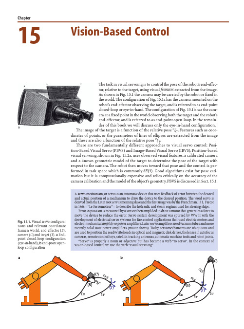
A servo-mechanism, or servo is an automatic device that uses feedback of error between the desired and actual position of a mechanism to drive the device to the desired position. The word servo is derived from the Latin root servus meaning slave and the first usage was by the Frenchman J.J.L. Farcot in 1868 – “Le Servomoteur” – to describe the hydraulic and steam engines used for steering ships.
Fig. 15.2. The two distinct classes of visual servo system
Image-based visual servoing, shown in Fig. 15.2b, omits the pose estimation step, and uses the image features directly. The control is performed in image coordinate space R2. The desired camera pose with respect to the target is defined implicitly by the image feature values at the goal pose. IBVS is a challenging control problem since the image features are a highly non-linear function of camera pose. IBVS is discussed in Sect. 15.2.
云计算导论第二版课后答案
云计算导论第二版课后答案1.在华为云计算中,创建快照时,当前磁盘被置为只读,系统自动在磁盘所在数据存储中创建增量磁盘,后续对该磁盘数据的编辑将保存在增量磁盘中,即增量磁盘表示磁盘当前状况和上次执行快照时的状况之间的差异。
对该磁盘再次创建快照时,当前增量磁盘均被置为只读,系统会在数据存储中再创建一一个增量磁盘。
() [单选题] *A.对(正确答案)B.错2.在华为FusionSphere中,以下关于磁盘精简配置能够实现以下哪些功能? ()*A.虚拟存储精简配置与操作系统,硬件完全无关,因此只要使用虚拟镜像管理系统,就能提供虚拟存储精简置配功能(正确答案)B.提供数据存储容量预警,可以设置阀值,当存储容量超过阀值时产生告警(正确答案)C.提供虚拟磁盘空间监控和回收功能(正确答案)D.当前不支持NTFS格式的虚拟机磁盘回收3.管理员在FusionCompute中,为主机添加存储接口,实现主机与存储设备对接。
以下哪些存储类型不需要添加存储接口? ()*A. FC-SAN存储(正确答案)B. IP-SAN存储C.本地硬盘(正确答案)D.本地内存盘(正确答案)4.一下关于FusionCompute里的CPUQOS技术的描述中,不正确的是? () [单选题] *A.通过调整‘预留’,份额’,‘限制’,实现对虚拟机CPU资源使用的控制B.‘份额’的作用是保证虚拟机计算能力的下限,即最少能使用多少资源(正确答案)C.‘份额’的作用是在计算资源不足时,根据多个虚拟机的相对CPU份额值进行资源的均衡和调整D.‘限制’的作用是虚拟机最多可使用的资源5.在FusionCompute中,需要对某虚拟机的一-块磁盘做修改,下列操作哪个可以实现? () [单选题] *A.将磁盘的配置模式从精简改为普通B.将磁盘的模式从从属改为独立-持久(正确答案)C.将磁盘的容量从80G修改为8GD.将磁盘的状态从可以修改为不可用6.在FusionSphere中创建一一个虚拟机,关于该虚拟机的网卡说法正确是? ()[单选题] *A.虚拟网卡和物理网络有本质的区别,虚拟网卡不需要MAC地址B.在虚拟网络中,虚拟网卡的MAC地址和IP地址都可以手动指定(正确答案)C.在虚拟网络中,虚拟网卡的MAC地址和IP地址都是由VRM自动分配的D.在虚拟网络中,虚拟网卡的IP地址需要手动指定7.在FusionCompute中,设置什么功能,可以使虚拟机可以在进行迁移? () [单选题] *A.集群I/0环适配B.集群HANA优化C.集群GuestNUMA策略D.集群IMC策略(正确答案)8.某公司自己搭建了桌面云环境仅供员工办公使用,属于哪种云计算部署模式?() [单选题] *A.公有云B.私有云(正确答案)C.政务云D.混合云9.在FusionCompute中,在VLAN池菜单下,下列哪些操作可以实现? () [单选题] *A.在同一个DVS中,添加10个VLAN池,并且每个VLAN池的VLANID相同B.在DVS下添加1个VLAN池,并且VLAN池的起始VLANID设为100(正确答案)C.在DVS下添加1个VLAN池,并且VLAN池的起始VLANID设为0D.在DVS下添加1个VLAN池,并且VLAN池的结束VLANID设为409610.以下哪些是FusionSphere的特点()*A.应用按需分配资源(正确答案)B.广泛兼容各种软硬件(正确答案)C.自动化调度(正确答案)D.丰富的运维管理(正确答案)11.在华为FusionSphere中,为主机添加哪些存储资源后,虚拟机的-一个磁盘对应存储中的一个LUN? ()*A. FusionStorage(正确答案)B.高级SAN(正确答案)C. FC-SAND. IP-SAN12.在FusionCompute中创建端口组时,以下操作错误的是哪个? () [单选题] *A.将端口组的名称设为ceshi’B.将端口组类型设为“普通C.将VLANID设为5000(正确答案)D.在描述中添加这是测试端口”13.在FusionCompute中,可以给虚拟机设置的QOS参数不包括: () [单选题] *A.内存B.CPUC.GPU(正确答案)D.磁盘IOPSE.网络14.以下运维工具中,用于在FusionSphere中进行信息收集和健康检查的工具是: () [单选题] *A. FusionSphere SoIB. FusionCare(正确答案)C. UpdateToolD. Fusi onManagerE. FusionCompute15. FusionCompute中,CNA 主要提供以下哪些功能? ()*A.管理集群内资源的动态调整B.提供虚拟计算功能(正确答案)C.管理计算节点上的虚拟机(正确答案)D.管理计算节点上的计算,存储,网络资源。
信息迷蜂系统手册说明书
InfoMolecubesA programmablerobot systemModular learningModularisation – a principle of natureModularisation is a basic principle of living nature: organisms consist of molecules and cells that use genetic programming in order to group together to form organs. Cell division and modularisation are the two mutually opposed aspects of reproduction in living systems.Modularisation is also the basis of the design of complex technical devices and machinery in all disciplines, from electrical engineering,mechatronics and robotics to IT and traffic systems.Learning, i.e. the application-oriented acquisition of knowledge, is also subject to design processes. Existing and newly acquired “knowledge modules” are modularly networked. Because of the complexity of the human brain, learning can only be externally controlled to a limited extent. The reinforcement or rejection of an organism’s own positive or negative “experience modules” appears to be the most efficient principle for sustainable learning; this learning by trial and error can best be observed among small children.Molecubes – learning by experimenting and programming This project is a further development of the “Molecube Systems”of Cornell University, Ithaca, USA, in the third generation. The geo-metrical basis of this system is a cube, to which further Molecubes can dock in all six directions like the molecules of a chemical com-pound. The two halves of a Molecube module rotate about the axis defined by two diagonally opposite corners. By linking together several Molecube elements, a practically unlimited number of spatialmovement variants for the entire system can be realised. The endmodules can also take the form of Molecubes with grippers, cameras or drive shafts.The configuration newly formed by the docking of a further element is directly communicated to all Molecubes within the system; this ensures that the energy supply and the transmission of signals from Molecube to Molecube is maintained.From reality to virtualityThe rigorously systematic approach of translating the mechanical configuration into corresponding data structures now also paves the way from the concrete structure to virtual reality – or in the language of the Massachusetts Institute of Technology (MIT): from atom to bit. Wireless data transmission enables the real configu-ration of the Molecubes to be replicated in a data model on a personal computer.Molecube with gripperThe Molecubes can be programmed in four different ways, ranging from manual to fully automated programming:High-level programmingThe interface for numerical calculations on the basis of matrices, similar to the MATLAB program, allows programming with direct drive commands, sensor signals, and the application of internal variables and of data flow control commands. At this level, elementary pro-gramming experience can be acquired through direct feedback. The source code is available e.g. for study units via compilers that can convert the source language into a target language, or for extension by experienced users.Direct programmingVia the ARM-processor interface, experienced users can program the robot directly in the programming language C++. A library enables direct communication with all sensors and actuators.Machine learningWith this interface, fully automatic programming by means of mechanical learning processes at the highest level for research purposes is possible. Reinforcement learning and evolutionary algorithms are the key words in this context.Graphic emulationRealistic graphic and physical emulation allows the robot to be tested and operated virtually. In virtual reality, the user can control geometric and physical parameters and for instance monitor a robot’s collision behaviour. The simulation data can be exchanged between several robots, e.g. for studying cooperative or competitive behaviour. Towards the learning moduleThis study demonstrates the general feasibility of such a versatile system. The positive experience gained with students of the Molecube Community at Cornell University and further universities throughout the world validates the chosen approach.The task of the next Molecubes development phase will be to drive forward mechanical and electronic integration. The objective here is to reduce the volume of the Molecubes even much further by means of technologies from Festo.With the Molecubes project, Festo is demonstrating a possible future learning environment that combines direct experience with the latest opportunities provided by modular software and robotics technology. Constructing and programming robots at first hand enhances experience and facilitates instruction in automation, and represents hands-on technology for youths and all interested specialists.Learning from practical experienceVersatile systems machinery and product design has long been partof Festo’s repertoire. The new CPX-CEC and PC Worx control units,with a universal programming interface in accordance with the IEC61131-3 standard and a modular electric periphery such as CPX,can dock as easily as molecules when a task list undergoes modifi-cation.X-ray image of a molecubeProject partnersProject initiator:Dr. Wilfried Stoll, Chairman of the Supervisory Board, Festo AG Project manager:Dr. Hermann Klinger, Festo AG & Co. KGConcept and design:Dr. Victor Zykov, Makani Power, Alameda, CA, USAProf. Dr. Hod Lipson, Cornell University, Ithaca, NY, USA Dr. Hermann Klinger, Festo AG & Co. KGMechanical components:Bastian Dolde, Walter Suchy, Festo AG & Co. KGChristoph Altekamp, Altekamp Werkstatt für Gestaltung, Stuttgart,GermanySoftware and electronics:Dr. Victor Zykov, Makani Power, Alameda, CA, USA Dr. Otto Szenn, Festo AG & Co. KG Photos:Walter Fogel, Angelbachtal, Germany Graphic design:Atelier Frank, Berlin, GermanyFesto AG & Co. KGBusiness DevelopmentKnowledgeRuiter Straße 8273734 Esslingen Germany Telefon +49 711/347-40 55Telefax +49 711/347-54 40 55kli @Technical dataEdge length of a Molecube:66 mmWeight: 200 g Torque: 4.85 Nm Rotation angle: continuous Rotation speed: max. 17 per minute Processors: 2 x ATMega16Servo controller: AX-12 with ATMega8Internal communication: single wire, max. 1 Mbps External communication: USB and Bluetooth Simulation: AGEIA PysX engine Graphics rendering:OGRE54715/EN。
PhidgetServo 4-Motor 使用手册说明书
1001 - PhidgetServo 4-MotorProgramming EnvironmentOperating Systems: Windows 2000/XP/Vista, Windows CE, Linux, and Mac OS XProgramming Languages (APIs): VB6, , C#.NET , C++, Flash 9, Flex, Java, LabVIEW , Python, Max/MSP , and Cocoa.Examples: Many example applications for all the operating systems and developmentenvironments above are available for download at .Product FeaturesControls 4 Remote Control (RC) servo motors.• The motor at position 0 is powered directly from the USB port • Motors 1, 2, and 3 are powered by an external power supply.• Step accuracy of 0.1 degrees• Requires a 6 to 12VDC external power supply.• Connects directly to a computer’s USB port.•The kit contains:A PhidgetServo 4-Motor • A USB cable• You will also need:2 servo motors• A 6 to 12VDC power supply,• Attach the connector from the servo motor onto the PhidgetServo board. The board is 1. labeled with B R W (Black Red White) to match the wire colors from servo motors. If you connect it backwards, it will not work! Many servo motors have a yellow wire instead of a white wire. Use the board connector labelled 0 for the first motor and the connector labelled 4 for the second one. Connect the PhidgetServo to your PC using the USB cable.2. Connect the power supply to the PhidgetServo using the barrel connector .3. 123Installing the hardwareDownloading and Installing the softwareIf you are using Windows 2000/XP/VistaGo to >> Downloads >> Windows Download and run Phidget21.MSI You should see theicon on the right hand corner of the Task Bar .Testing the PhidgetServo 4-Motor FunctionalityDouble Click on 1. Phidget Servo Controller4-motor in the Phidget Control Panel to bring up Servo-full and check that the box labelled Attached contains the word True.Select Servo motor 0.2. Move the slider to make the motor turn. The3. motor position is displayed in the box above the Slider.Note: To check the second motor just switch the Servo No to 4 (step 2) and redo step 3.312Double Click on the icon to activate the Phidget Control Panel and make sure that the Phidget Servo Controller 4-Motor is properly attached to your PC.Double Click on 1. Phidget Servo Controller 4-motor in the Phidget Preference Pane tobring up the Phidget Servo Controller Example and check that the Phidget Servo Controller is attached.Move the slider to make the first motor turn. 2. Move the slider to make the second motor turn.3. If you are using Mac OS XGo to >> downloads >> Mac Download Mac OS X FrameworkTesting the PhidgetServo 4-Motor functionalityClick on System Preferences >> Phidgets (under Other) to activate the Phidgets Preference Pane. Make sure that the Phidget Servo Controller 4-motor is properly attached.123If you are using LinuxGo to >> Downloads >> Linux•Download Linux Source•Have a look at the readme file•Build Phidget21The most popular programming languages in Linux are C/C++ and Java.Note: Many Linux systems are now built with unsupported third party drivers. It may be necessary to uninstall these drivers for our libraries to work properly.Note: Phidget21 for Linux is a user-space library. Applications typically have to be run as root, or udev/hotplug must be configured to give permissions when the Phidget is plugged in.If you are using Windows Mobile/CE 5.0 or 6.0Go to >> Downloads >> Windows Mobile/CEDownload x86 or ARMV4I, depending on the platform you are using. Mini-itx and ICOP systems will be x86, and most mobile devices, including XScale based systems will run the ARMV4I.The CE libraries are distributed in .CAB format. Windows Mobile/CE is able to directly install .CAB files.The most popular languages are C/C++, .NET Compact Framework ( and C#). A desktop version of Visual Studio can usually be configured to target your Windows Mobile Platform, whether you are compiling to machine code or the .NET Compact Framework.Programming a PhidgetPhidgets’ philosophy is that you do not have to be an electrical engineer in order to do projects that use devices like sensors, motors, motor controllers, and interface boards. All you needto know is how to program. We have developed a complete set of Application Programming Interfaces (API) that are supported for Windows, Mac OS X, and Linux. When it comes to languages, we support VB6, , C#.NET, C, C++, Flash 9, Flex, Java, LabVIEW, Python, Max/MSP, and Cocoa.ArchitectureWe have designed our libraries to give you the maximum amount of freedom. We do not impose our own programming model on you.To achieve this goal we have implemented the libraries as a series of layers with the C API at the core surrounded by other language wrappers.LibrariesThe lowest level library is the C API. The C API can be programmed against on Windows, CE, OS X and Linux. With the C API, C/C++, you can write cross-platform code. For systems with minimal resources (small computers), the C API may be the only choice.The Java API is built into the C API Library. Java, by default is cross-platform - but your particular platform may not support it (CE).The .NET API also relies on the C API. Our default .NET API is for .NET 2.0 Framework, but we also have .NET libraries for .NET 1.1 and .NET Compact Framework (CE).The COM API relies on the C API. The COM API is programmed against when coding in VB6, VBScript, Excel (VBA), Delphi and Labview.The ActionScript 3.0 Library relies on a communication link with a PhidgetWebService (see below). ActionScript 3.0 is used in Flex and Flash 9.Programming Hints•Every phidget has a unique serial number - this allows you to sort out which device is which at runtime. Unlike USB devices which model themselves as a COM port, you don’t have to worry about where in the USB bus you plug your phidget in. If you have more thanone phidget, even of the same type, their serial numbers enable you to sort them out at runtime.•Each phidget you have plugged in is controlled from your application using an object/handle specific to that phidget. This link between the phidget and the software object is created when you call the .OPEN group of commands. This association will stay, even if the phidget is disconnected/reattached, until .CLOSE is called.•The Phidget APIs are designed to be used in an event-driven architecture. While it ispossible to poll them, we don’t recommend it. Please familiarize yourself with eventprogramming.Networking PhidgetsThe PhidgetWebService is an application written by Phidgets Inc. which acts as anetwork proxy on a computer. The PhidgetWebService will allow other computers on the network to communicate with the Phidgets connected to that computer. ALL of our APIshave the capability to communicate with Phidgets on another computers that has the PhidgetWebService running.The PhidgetWebService also makes it possible to communicate with other applications that you wrote and that are connected to the PhidgetWebService, through the PhidgetDictionary object.API documentationWe maintain API manuals for COM (Windows), C (Windows/Mac OSX/Linux), Action Script, .Net and Java. Look at the section that corresponds to the Phidget you are using. These manuals can be accessed in different ways:Using Downloads on main menuClick on Downloads >> Operating System (i.e. Windows) >> Platform (i.e. C#) >> API Document (i.e. Net API Manual)Using Products on Home PageClick on InterfaceKits (under Products) >> 1018 PhidgetInterfaceKit 8/8/8 >> API Manual (Under Software Information)Using Information on Home PageClick on Information (under Main Menu) >> Your API Manual (under Phidgets API Manuals) ExamplesWe have written examples to illustrate how the APIs are used. Examples for the C#.NET programming language Include .exe files for each of the examples in the directory root.Due to the large number of languages and devices we support, we cannot provide examples in every language for every phidget. Some of the examples are very minimal, and other examples will have a full-featured GUI allowing all the functionality of the device to be explored. Most developers start by modifying existing examples until they have an understanding of the architecture.To get the examples, go to and click on Downloads. Under Step 2: click on your platform of choice and click on the File Name besides Examples.Support•Click on Live Support on to chat with our support desk experts•Call the support desk at 1.403.282.7335 8:00 AM to 5:00 PM Mountain Time (US & Canada) - GMT-07:00•************************Simple example written in C#/* - Servo simple -**************************************************************************************** * This simple example sets up a Servo objectm hooks the event handlers and opens it for * device connections. Once a Servo is attached with a motor in motor 0 it will simulate * moving the motor from position 15 to 231, displaying the event details to the console. * For a more detailed example, see the Servo-full example.** Please note that this example was designed to work with only one Phidget Servo* connected. For an example using multiple Phidget Servos, please see a “multiple”* example in the Servos Examples folder.** Copyright 2007 Phidgets Inc.* This work is licensed under the Creative Commons Attribution 2.5 Canada License.* To view a copy of this license, visit /licenses/by/2.5/ca/ */using System;using System.Collections.Generic;using System.Text;//Needed for the Servo class, Phidget base classes, and the PhidgetException class using Phidgets;//Needed for the Phidget event handling classesusing Phidgets.Events;//Using this simply for the sleep() method so that the for loop will wail for the motor //to finish moving to the previous new position before setting a new positionusing System.Threading;namespace Servo_simple{class Program{static void Main(string[] args){try{//Declare a Servo objectServo servo = new Servo();//Hook the basic event handlersservo.Attach += new AttachEventHandler(servo_Attach);servo.Detach += new DetachEventHandler(servo_Detach);servo.Error += new ErrorEventHandler(servo_Error);//hook the phidget specific event handlersservo.PositionChange += new PositionChangeEventHandler(servo_PositionChange);//open the Servo object for device connectionsservo.open();//Get the program to wait for a Servo to be attachedConsole.WriteLine(“Waiting for Servo to be attached...”);servo.waitForAttachment();//Set the initial position for the servo. I set it to 15 here just//since I am going to cycle through the positive values to show a basic//full movementif (servo.Attached){servo.servos[0].Position = 15.00;}double i;//Wait for the motor to finish getting into position and let the user//continueConsole.WriteLine(“Press any key to continue...”);Console.Read();//Move the motor from position value 15 to 231m we sleep for//10 milliseconds between each step to give the motor enough time to//move to the set positionif (servo.Attached){for (i = 15.00; i < 232.00; i++){Thread.Sleep(10);servo.servos[0].Position = i;}}//Wait for the events to fire and display, user input will continue the//programConsole.WriteLine(“Press any key to end...”);Console.Read();//user input was read so we can terminate the program now, close the//Servo objectservo.close();//set the object to null to get it out of memoryservo = null;//if no exceptions were thrown at this point it is safe to terminateConsole.WriteLine(“ok”);}catch (PhidgetException ex){Console.WriteLine(ex.Description);}}//Attach event handler...Display te serial number of the attached servo devicestatic void servo_Attach(object sender, AttachEventArgs e){Console.WriteLine(“Servo {0} attached!”, e.Device.SerialNumber.ToString()); }//Detach event handler...Display the serial number of the detached servo device static void servo_Detach(object sender, DetachEventArgs e){Console.WriteLine(“Servo {0} detached!”, e.Device.SerialNumber.ToString()); }//Error event handler....Display the error description to the consolestatic void servo_Error(object sender, ErrorEventArgs e){Console.WriteLine(e.Description);}//Position CHange event handler...display which motor changed position and//its new position value to the consolestatic void servo_PositionChange(object sender, PositionChangeEventArgs e){Console.WriteLine(“Servo {0} Position {1}”, e.Index, e.Position);}}}Technical SectionServo MotorsServos are motors that are typically usedwhen shaft position needs to be controlled.Internally, a servo motor’s shaft ismechanically connected to a potentiometer;this tells the motor’s integrated electronicsthe present position of the shaft. A pulse-code-modulated signal sent from thePhidgetServo on the control wire tells themotor the desired position of the shaft,which is set in software. The motor isthen powered until the current-position anddesired-position match.Pulse Code Modulation (PCM)A PCM signal has a defined period (typically20ms in servo applications) and a specified ON- and OFF-time. The ON-time is the amount of time during the period that the signal isat 5V; the rest of the time the signal is at 0V (the OFF-time). When using PCM with servo motors, one specific duration of ON-time will represent the minimum shaft position, and a different and longer duration ON-time will represent the maximum shaft position. The ON-time in between these two bounds is the setting where the shaft-position is centered. These values are defined by the motor manufacturer and vary between servo motors.Using the PhidgetServo with a Servo MotorThe PhidgetServo has been designed to be used with a variety of RC servo motors independant of the motor-specific position, velocity and torque limits. Select a motor that suits your application and falls within the PhidgetServo device specifications (see page 9). To use a servo motor, simply set the desired shaft position in software. It should be noted that the PhidgetServo can not sense the actual position of a servo on its own. The servo motor at position 0 is powered by the USB bus from the PC; an external power supply is only required to power motors as positions 1, 2, and 3.Calculating Servo Motor Pulse CodesThe width of the pulse sent from the PhidgetServo to the motor translates to an angular position of the motor shaft. In many cases, a pulse width of 1.5 milliseconds signifies the center position of the shaft; the upper and lower timing bounds depend on the manufacurer and model of the servo used. The timing of the pulse code can be calculated with the following formula: Pulse Width (in microseconds) = (Software MotorPosition + 23 ) * 10.6Servo Motor Gear SlopAlthough the PhidgetServo can position to an accuracy of 0.1 degrees, the repeatability of po-sitioning the shaft of a servo motor is affected by the servo motor’s gear slop. Gear slop is the amount of play between the interlocking teeth of gears within the servo motor. More expensive servo motors, built with precision gears, will have a smaller amount of gear slop, while cheaper RC servo motors constructed with plastic gears may have one degree or more.Using the PhidgetServo with Continuous Rotation ServosA continuous rotation servo is a servo motor that has had its headgear-stop removed and po-tentiometer replaced by two matched-value resistors. This has the effect of allowing the motor to rotate freely through a full range of motion, but disables the motor’s ability to control shaft position.When using the PhidgetServo with a servo motor modified in this way, position control in soft-ware becomes the motor’s speed control. Because the two resistors that replace the motor’s potentiometer are matched in value, the motor will always think its shaft is at center position. If the target position in software is set to center, the motor will believe it has achieved the target and will therefore not rotate. The further away from center the target position is set to, the faster the motor will rotate (trying to reach that position, but never doing so). Changing the value above or below center changes the direction of rotation.Using the PhidgetServo with PCM-to-DC Motor ControllersSome DC motor controllers accept a servo motor PCM signal as valid input, and use the signal to control the speed of a DC motor. Examples of these include Victor and Thorseries motor controllers from IFI Robotics. Operation of these are similar to the way the PhidgetServo is used to control continuous rotation servos, however DC motors with much higher voltage/current ratings can be driven. Note: a buffer on the control line is sometimes required when interfacing to these types of motor controllers, and can typically be purchased from the motor controller manufacturer.RC Servo MotorsThe PhidgetServo 4-Motor will work with a variety of small to medium sized 3-wire servo motors. A few motors are listed below.Manufacturer Part Number DescriptionHitec HS-55Feather Series RC Servo MotorHitec HS-322HD Deluxe Series RC Servo Motor (shown)Hitec HS-805BB Mega Quarter Scale RC Servo MotorThe Hitech HS-322HD is available for purchase at . Many RC servo motors are available directly from manufacturers like Hitec or at local distributors.API SectionWe document API Calls specific to the 1001 Phidgetservo 4-Motor. Functions common to all Phidgets are not covered here. This section is deliberately generic - for calling conventions in a specific language, refer to that languages’ API manual.Functionsint MotorCount() [get] : Constant = 4Returns the number of servos that can be controlled by this PhidgetServo. Note that there is no way of determining the number of servos actually attached.double Position(int ServoIndex) [get,set] : DegreesSets/returns the desired servo motor position for a particular servo motor.Note that reading Position will not tell you where the servo really is. RC Servos are open loop – the PhidgetServo can command them to travel to a position, but there is no feedback available for if they arrived, or their position.If the servo is not engaged, the position is unknown and calling this function will throw an exception.The range is between PositionMin and PositionMax, and corresponds aproximately to an angle in degrees. Note that most servos will not be able to operate accross this entire range. Typically, the range might be 25 - 180 degrees, but this depends on the servo.On the 1001 PhidgetServo 4-Motor, 0 is the servo motor powered by USB, and servos 1-3 are powered by an external power supply.double PositionMax(int ServoIndex) [get] : ConstantReturns the maximum position that the PhidgetServo will accept, or return.double PositionMin(int ServoIndex) [get] : ConstantReturns the minimum position that a PhidgetServo will accept, or return.bool Engaged(int ServoIndex) [get,set]If Engaged is set to false, no PWM signals will be sent to the servo. This engages or disengages the servo. The motor is engaged whenever you set a position, or use this function to disengage and reengage without setting a position.EventsOnPositionChange(int ServoIndex, double Position) [event]An event that is issued whenever the position of a PhidgetServo changes.Mechanical DrawingDevice SpecificationsPulse Code Period20 ms Minimum Pulse Width10 us Maximum Pulse Width2.55 ms Time Resolution1 us Output Controller Update Rate50 updates / second Output Impedance (control)600 Ohms Lower Position Limit- 23.00ºUpper Position Limit232.99ºOperating Motor Voltage5.0 V External Power Supply Voltage6 VDC - 12 VDC External Power Current Consumption1500 mA max (500 mA / motor)USB-Power Current Specification500 mA max Device Quiescent Current Consumption13 mA Device Active Current Consumption 500 mA max Hitech HS-322HD RC Servo Specifications ***********41.66 oz.in **********190ms/60ºSize L x W x H1.57” x 0.78” x 1.43”Weight1.51 oz.1:1 scaleProduct HistoryDate Product Revision CommentJune 2001DeviceVersion200 1 Degree Position Resolution June 2002DeviceVersion3000.1 Degree Position Resolution January 2004DeviceVersion313State Echoing Added。
ibvs原理 -回复
ibvs原理-回复IBVS原理:图像基于视觉的反馈控制原理导言:在自动化领域,图像基于视觉的反馈控制(Image-Based Visual Servoing,简称IBVS)是一种利用视觉信息来实现控制目标的自动化技术。
IBVS利用摄像机获取目标的视觉信息,然后根据预设的目标轨迹与当前视觉信息之间的误差,通过控制器驱动执行器,使得系统实现目标轨迹跟踪。
本文将对IBVS原理进行详细介绍,包括其基本步骤和关键技术。
一、IBVS基本步骤:1. 目标定义:首先需要定义要跟踪的目标,并通过摄像机获取目标的视觉信息。
这些信息通常包括目标的位置、姿态或者其它相关特征。
在IBVS中,目标通常以特征点、特征线或者特征面的形式被定义。
2. 三维姿态估计:通过使用摄像机的外参信息和目标的视觉信息,可以进行三维姿态的估计。
这一步骤通常包括计算目标在摄像机坐标系下的位置和旋转矩阵。
3. 误差计算:将目标的估计姿态与预设的目标轨迹进行比较,得到当前的误差信息。
误差通常以特征点或者特征线之间的距离或者角度差等形式表示。
4. 反馈控制:根据当前的误差信息,设计合适的控制器来驱动执行器,使得系统朝着轨迹目标前进。
控制器可以基于比例、积分、微分(PID)等常见的控制算法来实现。
控制器的目标是通过调整执行器的输出使得误差逐渐收敛到0,从而实现目标轨迹的稳定跟踪。
二、关键技术:1. 反馈适应性:在实际应用中,目标的视觉信息可能受到环境干扰、光照变化等因素的影响,导致估计误差。
为了提高系统的鲁棒性和适应性,可以引入反馈适应性技术来动态调整控制器参数。
例如,可以根据当前的估计误差和执行器输出的反馈信息来自适应调整控制器的增益。
2. 特征选择与提取:在IBVS中,选择合适的特征对于系统的性能至关重要。
特征的选择应该能够反映目标的运动和变化,同时具备良好的可观测性。
常用的特征包括边缘、角点、轮廓线等。
此外,通过合适的图像处理和计算方法来提取特征,可以提高系统对噪声、模糊等外界因素的鲁棒性。
- 1、下载文档前请自行甄别文档内容的完整性,平台不提供额外的编辑、内容补充、找答案等附加服务。
- 2、"仅部分预览"的文档,不可在线预览部分如存在完整性等问题,可反馈申请退款(可完整预览的文档不适用该条件!)。
- 3、如文档侵犯您的权益,请联系客服反馈,我们会尽快为您处理(人工客服工作时间:9:00-18:30)。
Figure 1 Approach envelope for SSRMS capturing a free-flyer [7] During capture of a free-flying satellite an astronaut controls the arm using images from the arm cameras and moves the end-effector through a sequence of way points defined relative to the satellite. The last waypoint before the capture is 1.5-2m away from the interface. At this distance the arm operator moves the end-effector so as to reduce the lateral offsets and orientation angles to zero. The capture is achieved with a single motion along the camera/end-effector axis, which minimises the time that the end-effector spends in the close proximity of the free-floating satellite. 2.2 Autonomous satellite capture Capturing free-floating satellites autonomously will most likely follow procedures developed for manned operations, and specifically the concepts of way points, incremental alignment and stay-out zones. A vision system will process intensity or range images and estimate pose (position and orientation) of the satellite and the interface. The cameras may be mounted on the servicer and/or the manipulator. An end-effector camera will be used for the close range operations. The initial distance between the end-effector and target spacecraft will depend on the arm size and design, and whether the spacecraft control will be integrated with the arm control, and will range from several to tens of meters. The final position corresponds to a distance between the end-effector camera and the satellite surface in the captured position (0.2-0.5m). During the operation the vision system will have to fixate the cameras on the observed object ensuring that neither the satellite drift or end-effector motion could cause loss of visibility and data. 3 VISUAL SERVOING APPROACHES Visual servoing is typically classified into position based, image based and hybrid servoing [4]. All of the approaches attempt to minimise an error between the set and measured values. However, they differ in which error function is minimised and the type of measurements performed by the vision system. A thorough analysis and comparison of these methods is presented in [6]. Image based methods operate by extracting image features, matching them with their desired locations, and minimising the image plane error between them. Pose based methods minimise an error between measured and required pose in the Cartesian space. Image based methods appear attractive as their computational cost is lower - it is not necessary to compute the 3D pose of the observed object. However, the visual servoing task must be expressed as a sequence of feature locations in images instead of a series of Cartesian frames of reference. In our work we rely on position based visual servoing approach as full pose information (6 dof) is computed by our vision systems. 4 MDR VISION SYSTEM A vision system for satellite proximity operations, which include satellite capture using a manipulator, is described in a companion paper [5]. This vision system uses stereo cameras and a satellite model to compute pose of the observed satellite if it is within stereo range (medium range). At a short range (below the stereo range) the vision system operates in a monocular mode. The vision system automatically acquires initial pose of the satellite (or interface) and tracks it in subsequent images. The system automatically reconfigures itself during the operation depending on the distance and relative orientation between the satellite and cameras. The prototype vision system tracks satellite pose at the rate of 2Hz in the medium range (1.2m - 5m) and 12 Hz in the short range (below 1.5m) [5]. The system operates successfully under expected space conditions (illumination, space materials, viewing angles and distances), that cause partial data loss due to shadows, occlusions and specular reflections. At each phase of the operation the vision system computes confidence of estimated values. Low confidence may trigger reacquisition of pose and continuation of tracking, altering the controller behaviour or aborting the operation.
Michael Liu, Piotr Jasiobedzki
MD Robotics, 9445 Airport Rd., Brampton ON, Canada, L6S 4J3 {mliu, pjasiobe}@mdrobotics.ca
1 INTRODUCTION Unmanned space servicing requires an