并行乘法器-南京理工大学紫金学院vhdl实验报告-eda
南京理工大学EDA设计实验报告

目录设计一单级放大电路设计 (3)一、设计要求 (3)二、实验原理图 (3)三、实验过程及测试数据 (3)1. 调节电路静态工作点,测试电路饱和失真、截止失真和不失真的输出信号波形图,以及三种状态下电路静态工作点值。
(3)2. 在正常放大状态下,测试三极管输入、输出特性曲线以及、的值。
(7)3. 在正常放大状态下,测试电路的输入电阻、输出电阻和电压增益。
.94. 在正常放大状态下,测试电路的频率响应曲线和、值。
(10)四、实验数据整理 (11)五、实验数据分析 (11)设计二差动放大电路设计 (13)一、设计要求 (13)二、实验原理图 (13)三、实验过程及测试数据 (13)1.双端输出时,测试电路每个三极管的静态工作点值和、、值。
(13)2. 测试电路双端输入直流小信号时,电路的、、、值。
173. 测试射级恒流源的动态输出电阻。
(21)四、实验数据整理 (21)五、实验数据分析 (22)设计三负反馈放大电路设计 (24)一、设计要求 (24)二、实验原理图 (24)三、实验过程及测试数据 (24)1. 测试负反馈接入前,电路的放大倍数、输入电阻、输出电阻。
(24)2. 测试负反馈接入后,电路的放大倍数、输入电阻、输出电阻并验证。
(25)3. 测试负反馈接入前,电路的频率特性和、值,以及输出开始出现失真时的输入信号幅度。
(27)4. 测试负反馈接入后,电路的频率特性和、值,以及输出开始出现失真时的输入信号幅度。
(28)四、实验数据整理 (30)五、实验数据分析 (31)设计四阶梯波发生器设计 (31)一、设计要求 (31)二、实验原理图 (32)三、实验过程及与仿真结果 (32)1.方波发生器 (33)2.方波电路+微分电路 (34)3.方波电路+微分电路+限幅电路 (35)4.方波电路+微分电路+限幅电路+积分电路 (36)5.阶梯波发生总电路 (36)四、实验结果分析 (38)五、技术改进 (38)设计一单级放大电路设计一、设计要求1.设计一个分压偏置的单管电压放大电路,要求信号源频率20kHz,峰值5mV,负载电阻1.8kΩ,电压增益大于50。
EDA乘法器实验报告
实验七综合实验四位移位相加法乘法器一:实验内容用移位相加法设计一个四位(4bit)乘法器二:实验原理4bit 乘法器的电路实现方法有多种,其中典型的电路有两种,其一:用组合电路实现,该电路将用到三个4bit 加法器,16 个两输入与门,该电路的特点:设计电路简单直观,电路运算速度快。
但缺点是使用器件较多,连线较多。
其二:就是本实验中要用的部分积。
移位相加的方法实现的4bit 乘法器。
部分积移分相加乘法器的算法。
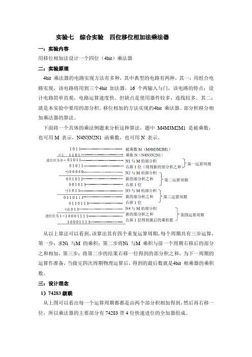
下面将一个具体的乘法例题来分析这种算法,题中M4M3M2M1 是被乘数,也可用M 表示,N4N3N2N1 函乘数,也可用N 表示。
从以上算法可以看到,该算法其有四个重复运算周期,每个周期共有三步运算,第一步:求Ni 与M 的乘积;第二步将Ni 与M 乘积与前一个周期右移后的部分之和相加,第三步:将第二步的结果右移一位得到的部分积之和,为下一周期的运算作准备,当做完四次周期物理运算后,得到的最后数就是4bit 相乘器的乘积数。
三:设计理念1)74283级联从上图可以看出每一个运算周期都都是由两个部分积相加得到,然后再右移一位,所以乘法器的主要部分有74283带4位快速进位的全加器组成。
将乘法器打包成如下形式波形图:在时钟的每一个上升沿的时候,乘法器进行运算。
2)将二进制转换为10进制但是由于要在七段LED数码管中显示,所以原始的输出形式不能满足,因为上边的器件输出的是二进制,所以要将输入的乘数被乘数和结果转化为10进制,最大四位二进制即十进制的15,将被乘数A【3..0】和乘数B【3..0】除以10,余数即为个位,同理输出的结果最大为225,连续两次除以10,分别得到个位,十位的数,这样就将二进制的乘数,被乘数和结果转化为了10进制的数,从而方便了数码管的显示。
如图:rl rm rn个位,q4 q5 rh十位,q2百位。
3)选择器下面是将输出结果用7449译码器译码到数码管中,但是一个译码器不能同时译码(最多7个)数据,所以要用时钟信号以及多选器。
南理工紫金学院eda实验一

EDA技术与应用
实验报告
实验名称:软件和实验箱的介绍
姓名:Aa
学号:120403
班级:12级电科
时间:2014.12.3
南京理工大学紫金学院电光系
一、 实验目的(四号+黑体)
1、讲解Quartus Ⅱ软件和实验箱的使用。
2、利用原理图输入法实现4位串行进位加法器。
3、重点掌握软件使用过程中工程建立、原理图输入方法、编译、仿真、管脚配置等。
二、 实验原理
全加器表达式为:
4位串行进位加法器逻辑图:
三、 实验内容
一位全加器的原理图及其波形
1
i i i i S A B C -=⊕⊕1()i i i i i i
C A B C A B -=⊕
+全加器逻辑符号:
四位全加器的构造图及其波形
四、小结与体会
1、通过本次试验熟悉了quartus软件的使用,建立工程和建立文件的方法。
2、学会了使用原理图进行电路设计。
3.学会编译和仿真波形,观测实验现象。
南理工EDA实验一报告

南京理工大学EDA设计(Ⅰ)实验报告作者: 蒋华熔学号:1104210121 学院(系):电子工程与光电技术学院专业: 电子信息工程指导老师:吴少琴实验日期: 2013/8/26~2013/8/292013 年 9 月摘要EDA 技术的发展, 大大缩短了电子系统开发的周期, 且已成为开发技术的主流,EDA 综合实验开发, 为培养学生掌握EDA 技术的设计方法和微机控制技术在EDA 设计中的应用提供帮助,EDA 技术作为电子设计领域中的新兴技术,具有传统电子设计方法不可替代的高效、实用优势, 对于理工科, 尤其是电类相关专业学生及设计人员是必不可少的设计工具的熟练掌握这门技术尤为重要,EDA 综合实验的开发充实了专业课程的实验内容, 改进了实验方法与手段, 为学生创建了一个开放式、综合性的实验教学环境, 有利于培养学生的综合能力和创新能力关键词: EDA仿真实验开发技术元器件工作原理AbstractThe development of EDA technology, greatly shorten the cycle of electronic systems development, and has become the mainstream of development technology, EDA experiment development, and gives the implementation code, for trains the student to master the design method of EDA technology and microcomputer control technology in the application of EDA design help as emerging in the field of electronic design technology, EDA technology with traditional electronic design method is an irreplaceable efficient and practical advantages, for science and engineering, especially in electrical or related professional students and designers are essential design tool for mastering this technology is very important to the comprehensive experiment 1 EDA development enrich experiment contents of professional course, improve the experimental methods and means, for students to create an open, comprehensive experimental teaching environment, to cultivate students' comprehensive ability and innovation ability. The code of programming is given in this paper.Key words :EDA technology ; integrated experiment ;目 录实验一 单级放大电路的设计与仿真 (6)一、实验目的 (6)二、实验要求 (6)三、实验步骤 (6)1、电路的饱和失真和截止失真和最大不失真分析 (7)2、三极管特性测试 (11)3.电路基本参数测定 (17)四、实验小结 (20)实验二 差动放大电路的设计与仿真 (21)一、实验目的 (21)二、实验要求 (21)三、实验步骤 (21)1、电路的原理 (21)2.电路电压增益的测量 (22)四、实验小结 (27)实验三 负反馈放大电路的设计与仿真 (28)一、实验目的 (28)二、实验要求 (28)三、实验步骤 (28)1.负反馈接入前后放大倍数f A 、输入电阻i R 、输出电阻o R 的测定 (29)2.负反馈对电路非线性失真的影响 (36)四、实验小结 (40)实验四 阶梯波发生器电路的设计 (41)一、实验目的 (41)二、实验要求 (41)三、电路步骤 (41)1.方波发生器 (42)2.微分电路 (43)3.限幅电路 (45)4.积分电路 (46)5.比较器及电子开关电路 (47)四、实验小结 (49)参考文献 (50)实验一 单级放大电路的设计与仿真一、 实验目的1.掌握放大电路静态工作点的调整和测试方法;2.掌握放大电路的动态参数的测试方法;3.观察静态工作点的选择对输出波形及电压放大倍数的影响。
南京理工大学EDA(2)实验报告

南京理⼯⼤学EDA(2)实验报告南京理⼯⼤学EDA(2)实验报告--------多功能数字钟学⽣姓名:林晓峰学号:912104220143 专业:通信⼯程指导教师:2014年12⽉10⽇摘要本次实验利⽤QuartusII7.0软件设计了⼀个具有24⼩时计时、保持、清零、快速校时校分、整点报时、动态显⽰等功能的的多功能数字钟。
并利⽤QuartusII7.0软件对电路进⾏了详细的仿真,同时通过SMART SOPC实验箱对电路的实验结果进⾏验证。
报告分析了整个电路的⼯作原理,还分别说明了设计各⼦模块的⽅案和编辑、仿真、并利⽤波形图验证各⼦模块的过程。
并且介绍了如何将各⼦模块联系起来,合并为总电路。
最后对实验过程中产⽣的问题提出⾃⼰的解决⽅法。
并叙述了本次实验的实验感受与收获。
关键词:QuartusII7.0 多功能数字钟保持清零整点报时校时校分动态显⽰ SMART SOPCAbstractThis experiment uses the QuartusII7.0 software todesign one to have 24 hours time, the maintenance, the reset,the fast timing school minute,the integral point reportstime and so on digital clocks.And using the QuartusII software realizes the multi-purpose digital clock simulation. Through the SmartSOPC experiment box, I confirm the result of this experiment.The report analyzes the electric circuit principle of work,and also illustrates the design of each module and editing, simulation, and the process of using the waveformto testing each Sub module. Meanwhile,it describes how the modules together, combined for a total circuit. Finally the experimental problems arising in the process of presenttheir solutions. And describes the experience and resultof this experiment.Keywords:QuartusII7.0 Digital clock maintenancereset time alarm change minute and hour quickly dynamic display SMART SOPC⽬录封⾯ (1)摘要 (2)Abstract (3)⽬录 (4)1.设计要求 (5)2.实验原理 (6)3.模块电路设计 (7)3.1 脉冲发⽣电路 (7)3.2计数器 (10)3.3计时校正电路 (13)3.4整点报时电路 (17)3.5译码显⽰电路 (18)3.6附加电路 (19)4. 总电路图 (20)5.电路下载 (20)6.实验感想和收获 (21)6.1遇到的问题与解决⽅案 (22)6.2收获与感受 (23)6.3期望及要求 (23)7. 参考⽂献 (23)1.设计要求本次EDA设计利⽤Quartus II7.0软件设计⼀个多功能数字钟,并下载到Smart SOPC实验系统中进⾏验证。
三位计时电路设计,南京理工大学紫金学院vhdl实验报告,eda

EDA技术与应用实验报告实验名称:三位计时电路设计姓名:学号:班级:通信时间:2013南京理工大学紫金学院电光系一、实验目的1、学习利用顺序语句描述电路的方法。
2、学习进程、常用顺序语句的使用。
3、掌握分频电路的设计;掌握利用不完整条件语句构成时序逻辑电路的方法。
二、实验原理1、if语句if语句是具有条件控制功能的语句,它根据指定的条件及其条件是否成立来确定语句的执行顺序,格式如下。
1)格式1if 条件1 then第1组顺序语句;Elsif 条件2 then第2组顺序语句;……elsif 条件 n then第n组顺序语句;else第n+1组顺序语句;end if;在该形式的if语句中,只要满足条件1到条件n中的一个条件就执行一条顺序语句,且最优先的条件为条件1,次要的条件列到后面。
2)格式2(嵌套)if 条件1 thenif 条件2 then……一组顺序语句end if;end if;在该形式的if语句中,只有满足条件1到条件n中的所有条件才能执行相应的顺序语句,且最优先的条件为条件1,次要的条件列到后面。
3)格式3if 条件 then顺序语句;else顺序语句;end if;注意:只有不完整的条件语句才能构成时序逻辑电路,完整的条件语句只能构成组合逻辑电路。
2、进程语句进程主要用于描述顺序语句,其格式如下:标记:process (敏感信号表)声明语句;begin顺序语句end process;声明语句中可以定义一些局部量,可以包括数据类型、常数、变量、属性、子程序等,不能定义信号。
进程语句本为一无限循环语句,进程的启动由敏感信号的变化来启动,否则必须有一个wait语句来激励。
虽然进程中包含了顺序语句,但是进程本身是并行语句,即同一结构体中不同进程是并行运行的。
信号和变量3、信号信号代表电路内部信号传输线路,在元件之间起互连作用,相当于连线,可以通过端口和其他模块相连接。
说明:1)信号时一个全局量,可以在ENTITY和ARCHITECTURE中定义,不可以在进程和子程序的顺序语句中定义信号,但可以在VHDL语句的并行部分和顺序部分同时使用。
南理工EDA1优秀实验报告(含思考题)
南京理工大学EDA设计(Ⅰ)实验报告作者: 耿乐学号:913000710013 学院(系):教育实验学院专业: 机械类指导老师:宗志园实验日期: 2015年9月摘要本报告对单级放大电路、差分放大电路、多级放大反馈电路和简单的阶梯波发生器进行了设计和分析。
文中对电路中各个参数对电路性能的影响做了详细的实验和数据分析,并和理论数据进行对比,帮助我们更深刻的理解模拟电路中理论与实验的关系,指导我们更好的学习。
关键词模拟电路设计实验分析理论对比AbstractThis report on the single-stage amplifier, differential amplifier, feedback circuit and multi-level amplification of the trapezoidal wave generator for a simple design and analysis. The article on the various circuit parameters on circuit performance in detail the experiments and data analysis, and compare data and theory to help us gain a deeper understanding of analog circuits in the relationship between theory and experiment, to guide us to better learning.Keywords Analog Circuit Design Experimental analysis Theoretical comparison目录实验一单级放大电路设计 (1)实验二差动放大电路设计 (11)实验三负反馈放大电路设计 (21)实验四阶梯波发生器设计 (27)单级放大电路设计一、实验要求1.设计一个分压偏置的单管电压放大电路,要求信号源频率10kHz,峰值5mV,负载电阻3.9kΩ,电压增益大于60;2.调节电路静态工作点,观察电路出现饱和失真和截止失真的输出信号波形,并测试对应的静态工作点值;3.在正常放大状态下测试:a.电路静态工作点值;b.三极管的输入、输出特性曲线和β、r be、r ce值;c.电路的输入电阻、输出电阻和电压增益;d.电路的频率响应曲线和f L、f H值。
南京理工大学EDA2实验报告
南京理工大学EDA(二)实验报告学号:姓名:学院:指导老师:时间: 2014年11月30日摘要:本实验通过使用 QuartusⅡ软件,并结合数字逻辑电路的知识设计多功能数字钟,可以实现正常的时、分、秒的计数功能,分别由六个数码管显示计时,可以利用开关实现系统的计时保持、清零和校分、校时、校星期的功能。
同时,该电路系统还可以完成在59'53'', 59'55'', 59'57''低音报时, 59'59''高音报时的基本功能。
在此基础上,本实验还设计了扩展功能,包括星期计时、校星期以及通过开关与门电路切换到秒表计时的功能。
我原本还尝试设计闹钟的功能,但是闹钟的扩展功能还不够完善,目前完成了切换显示部分,但是报时还存在缺陷。
在利用 QuartusⅡ进行相应的设计、仿真、调试后下载到 SmartSOPC 实验系统上验证设计的正确性。
关键词:QuartusII,数字钟,分频,计时显示,保持清零,校分校时校星期,报时,星期计数,秒表Abstract:This experiment is based on QuartusⅡ,with the help of knowledge regarding the digital logic circuits and system design,to design a multifunctional digital clock. The basic function of the multifunctional digital clock is a 24-hour timer, and the exact time can be showed by six led lights. Also we can achieve the functions like time keeping, clearing and time and week adjusting by using the switches. Beyond the basic function, I improved the multifunctional digital clock and it can beep in low frequency at 59'53'', 59'55'', 59'57'' and in high frequency at 59'59''. Based onthis the basic design,I also design extra functions,including week timer ,week-time adusting and the stopwatch which can be exchanged by using the switchs and several circuits of logic and doors.Also I intended to design the alarm clock.,but unfortunately,the extra function of alarm clock is not perfect.Currently,I just have finished the functions containing the parts of exchange and display.But the part of beeping still needs improved.All the designing and simulating work are based on QuartusⅡ. After all the work finished on computer, I downloaded the final circuit to SmartSOPC experiment system to test the accuracy of the design.Key words: QuartusⅡ, digital clock ,reckon by time and display,time keeping and clearing, time adjusting, chiming, week timer,stopwatch目录一、题目简介 (5)二、设计要求 (5)三、方案论证 (5)四、设计原理 (6)1 脉冲发生器 (6)2 计数器设计 (9)3 计时电路、校正电路 (12)4 报时电路 (15)5 译码显示器 (16)五、附加功能 (18)1 星期功能 (18)2 秒表功能 (18)3 倒计时器 (18)4 开关复用 (19)5 切换电路............................................................................................. 错误!未定义书签。
- 1、下载文档前请自行甄别文档内容的完整性,平台不提供额外的编辑、内容补充、找答案等附加服务。
- 2、"仅部分预览"的文档,不可在线预览部分如存在完整性等问题,可反馈申请退款(可完整预览的文档不适用该条件!)。
- 3、如文档侵犯您的权益,请联系客服反馈,我们会尽快为您处理(人工客服工作时间:9:00-18:30)。
EDA技术与应用实验报告实验名称:并行乘法器姓名:学号:班级:通信时间:2013南京理工大学紫金学院电光系一、实验目的1、学习包集和元件例化语句的使用。
2、学习FLU(全加器单元)电路的设计。
3、学习并行乘法电路的设计。
二、实验原理并行乘法器的电路原理图如下图所示,主要由全加器和与门构成。
并行乘法器原理图三、实验内容1、and_2library ieee;use ieee.std_logic_1164.all;entity and_2 isport (a,b:in std_logic;y:out std_logic);end and_2;architecture and_2 of and_2 isbeginy <= a and b;end and_2;2、faulibrary ieee;use ieee.std_logic_1164.all;entity fau isport (a,b,cin:in std_logic;s,cout:out std_logic);end fau;architecture fau of fau isbegins <= a xor b xor cin;cout <= (a and b)or(a and cin)or(b and cin);end fau;3、top_rowlibrary ieee;use ieee.std_logic_1164.all;use work.my_components.all;entity top_row isport (a:in std_logic;b:in std_logic_vector(3 downto 0);sout,cout:out std_logic_vector(2 downto 0);p:out std_logic);end top_row;architecture structural of top_row isbeginU1: component and_2 port map(a,b(3),sout(2));U2: component and_2 port map(a,b(2),sout(1));U3: component and_2 port map(a,b(1),sout(0));U4: component and_2 port map(a,b(0),p);cout(2) <= '0';cout(1) <= '0';cout(0) <= '0';end structural;4、mid_rowlibrary ieee;use ieee.std_logic_1164.all;use work.my_components.all;entity mid_row isport (a:in std_logic;b:in std_logic_vector(3 downto 0);sin,cin:in std_logic_vector(2 downto 0);sout,cout:out std_logic_vector(2 downto 0);p:out std_logic);end mid_row;architecture structural of mid_row issignal and_out:std_logic_vector(2 downto 0);beginU1: component and_2 port map(a,b(3),sout(2));U2: component and_2 port map(a,b(2),and_out(2));U3: component and_2 port map(a,b(1),and_out(1));U4: component and_2 port map(a,b(0),and_out(0));U5: component fau port map(sin(2),cin(2),and_out(2), sout(1), cout(2));U6: component fau port map(sin(1),cin(1),and_out(1), sout(0), cout(1));U7: component fau port map(sin(0),cin(0),and_out(0), p, cout(0));end structural;5、lower_rowlibrary ieee;use ieee.std_logic_1164.all;use work.my_components.all;entity lower_row isport (sin,cin:in std_logic_vector(2 downto 0);p:out std_logic_vector(3 downto 0));end lower_row;architecture structural of lower_row issignal local:std_logic_vector(2 downto 0);beginlocal(0) <= '0';U1: component fau port map(sin(0),cin(0),local(0), p(0),local(1));U2: component fau port map(sin(1),cin(1),local(1), p(1),local(2));U3: component fau port map(sin(2),cin(2),local(2), p(2),p(3));end structural;6、my_componentslibrary ieee;use ieee.std_logic_1164.all;package my_components iscomponent and_2 isport (a,b:in std_logic; y:out std_logic);end component;component fau isport (a,b,cin:in std_logic; s,cout:out std_logic); end component;component top_row isport (a:in std_logic;b:in std_logic_vector(3 downto 0);sout,cout:out std_logic_vector(2 downto 0);p:out std_logic);end component;component mid_row isport (a:in std_logic;b:in std_logic_vector(3 downto 0);sin,cin:in std_logic_vector(2 downto 0);sout,cout:out std_logic_vector(2 downto 0);p:out std_logic);end component;component lower_row isport (sin,cin:in std_logic_vector(2 downto 0);p:out std_logic_vector(3 downto 0));end component;end my_components;7、multiplierlibrary ieee;use ieee.std_logic_1164.all;use work.my_components.all;entity multiplier isport (a,b:in std_logic_vector(3 downto 0);prod:out std_logic_vector(7 downto 0));end multiplier;architecture structural of multiplier istype matrix is array (0 to 3)ofstd_logic_vector (2 downto 0);signal s,c:matrix;beginU1: component top_row port map (a(0),b,s(0),c(0),prod(0));U2: component mid_row port map (a(1),b,s(0),c(0),s(1), c(1),prod(1));U3: component mid_row port map (a(2),b,s(1),c(1),s(2), c(2),prod(2));U4: component mid_row port map (a(3),b,s(2),c(2),s(3), c(3),prod(3));U5: component lower_row port map(s(3),c(3),prod(7 downto 4));end structural;8、仿真9、把multiplier代码改为百位、十位、个位输出代码如下:library ieee;use ieee.std_logic_1164.all;use ieee.std_logic_unsigned.all;use work.my_components.all;entity multiplier isport (a,b:in std_logic_vector(3 downto 0);hun,ten,one:out std_logic_vector(3 downto 0)); end multiplier;architecture structural of multiplier istype matrix is array (0 to 3)ofstd_logic_vector (2 downto 0);signal s,c:matrix;signal p:std_logic_vector(7 downto 0);beginU1: component top_row port map (a(0),b,s(0),c(0),p(0));U2: component mid_row port map (a(1),b,s(0),c(0),s(1), c(1),p(1));U3: component mid_row port map (a(2),b,s(1),c(1),s(2), c(2),p(2));U4: component mid_row port map (a(3),b,s(2),c(2),s(3), c(3),p(3));U5: component lower_row port map(s(3),c(3),p(7 downto 4));process(p)variable temp:std_logic_vector(7 downto 0);beginif p >"1100_0111" thenhun <="0010";temp:=p-"1100_1000";elsif p>"0110_0011" thenhun <="0001";temp:=p-"0110_0100";elsehun <="0000";temp:=p;end if;if temp>"0101_1001" thenten <="1001";temp:=temp-"0101_1010"; elsif temp>"0100_1111" then ten <="1000";temp:=temp-"1010_0000"; elsif temp>"0100_0101" then ten <="0111";temp:=temp-"0100_0110"; elsif temp>"0011_1011" then ten <="0110";temp:=temp-"0011_1100"; elsif temp>"0011_0001" then ten <="0101";temp:=temp-"0011_0010"; elsif temp>"0010_0111" then ten <="0100";temp:=temp-"0010_1000"; elsif temp>"0001_1101" then ten <="0011";temp:=temp-"0001_1110"; elsif temp>"0001_0011" then ten <="0010";temp:=temp-"0001_0100"; elsif temp>"0000_1001" then ten <="0001";temp:=temp-"0000_1010"; elseten <="0000";temp:=temp;end if;one <=temp(3 downto 0);end process;end structural;四、小结与体会通过本次实验,我对包集和元件例化语句的使用有了更深刻的了解。