ZH07系列传感器说明书
CS-iTVP-07-SS 无线双模车位占用状态传感器使用说明书

CS-iTVP-07无线双模车位智能监测车位终端使用说明书(CS-iTVP-07-SS)(REV A)西安中星测控有限公司修订履历注:本签署页仅限公司内部使用,对外不发放。
目录1.概述 (5)1.1产品简介 (5)1.2工作原理 (5)1.3产品分类 (5)1.4主要功能 (5)1.5主要特点 (5)1.6产品架构 (6)1.7产品图片 (6)2.主要设计指标 (6)2.1.主要技术参数 (6)3.使用说明 (8)3.1产品使用步骤 (8)3.2SIM卡安装说明(仅用于NB-Iot传输方式) (9)3.3电池更换说明 (10)3.4入网说明 (10)3.5通信协议 (10)4.安装说明 (11)5.选型指导 (13)6.安装及配置附件 (14)7.注意事项 (14)8.故障分析与排除 (15)9.声明 (16)双模无线车位智能监测车位终端使用说明书1.概述1.1产品简介CS-iTVP-07系列的双模检测的无线车位占用状态传感器(简称双模车位传感器),是一款集成了三轴磁阻传感器,毫米波雷达传感器,无线NBIOT和LORAWAN传输方式,低功耗管理技术的智能停车监测产品,融合高效的双模联合检测算法,对车位上的磁场扰动变化进行监测,并通过毫米波雷达传感器进行状态确认,综合算法分析判断出该车位处于占用或空闲状态。
支持LORAWAN、NB-IOT等多种传输方式上传数据至网关或运营商基站,网关或基站再传输至远程服务器。
该产品采用大容量电池供电,低功耗管理设计,埋入地面安装,壳体分体式设计,具有检出率高、工作稳定、无需布线、安装方便,维护简单,使用寿命长等特点,适用于室内停车场、市政路边停车、露天停车场,非法占道检测,违停监测等应用场合的智能管理。
1.2工作原理地球磁场的静态强度在0.5 至0.6 高斯,地球磁场在很广阔的区域内(大约几公里)其强度是一定的。
当一个铁磁性物体,如汽车,置身于磁场中,它会使磁场扰动,放置于其附近的磁阻车位终端能测量出地磁场强度的变化,从而对车辆的存在性进行判断,在实际应用中发现,目前存在部分车辆(面包车,国产部分车型或新能源车,国外的尺寸紧凑的单人或双人的小型车)的磁场扰动和背景磁场比较接近,难以探测到的问题,还有部分停车位周围有建筑施工,地铁高铁等运行对磁场数据有一定的干扰,所以结合毫米波雷达技术可以很好的解决因为周围磁场干扰和变化微小而引起的漏检或误检问题,从而提高车辆检测准确率。
ZH-HMI70使用手册

ZH系列一体机用户手册(ZH-HMI70)在安装、运行、维护、检查可编程控制器之前,请务必熟读该使用说明书以及相关的所有附带资料,正确使用。
请在熟悉了所有设备的相关知识、安全信息,以及注意事项后使用。
在该说明书中,用【危险】和【注意】对安全注意事项进行等级区分。
此外,即使是【注意】中记载的事项,因具体情况不同,也可能带来严重的后果。
由于记载的都是重要的内容,所以务必遵守。
此外,请妥善保管好产品中附带的使用说明书,以便需要时可以取出阅读,并且必须将其交至最终使用者手中。
1.设计方面的注意事项【危险】:错误使用时,会引起危险,有可能导致死亡,或是受到重伤的情况下。
【注意】:错误使用时,会引起危险,有可能受到中度的伤害或受轻伤的情况下,以及可能产生物质损失的情况下。
2.在安装方面的注意事项3.接线方面的注意事项4.启动、维护时的注意事项5.废弃时注意事项目录1.概述 (7)1.1.基本构造 (7)1.2.安装尺寸图 (8)1.3.型号命名 (8)1.4.编程软件 (9)1.4.1.HMI编程软件 (9)1.4.2.PLC编程软件 (10)1.5.规格参数 (11)1.5.1.一般规格 (11)1.5.2.HMI性能规格 (12)1.5.3.PLC性能规格 (12)2.单元端子和外部布线 (15)2.1.单元端子排列 (15)2.2.输入规格和外部布线 (15)2.3.输出规格和外部布线 (18)2.4.选件规格和外部布线 (19)2.4.1.模拟量输入 (19)2.4.2.模拟量输出 (20)2.4.3.温度模块 (21)2.4.4.RS485模块 (22)3.特殊软元件 (22)4.指令一览表 (32)1.概述ZH系列一体机是一款性价比超值的一体机。
其中的PLC部分,它兼容FX2N的全部基本指令和常用功能指令,还兼容三菱FX1N/1S的定位指令,完全可以替代三菱FX2N/FX1N/FX1S。
1.1.基本构造A:输入端X B:温度和模拟量C:输出端Y D:USB从站口,HMI下载用E:USB主站口,传输程序用F:COM0,PLC编程用G:COM1,PLC扩展通讯口H:电源输入I:模拟量输出J:指示灯1.2.安装尺寸图单位:毫米产品尺寸:正面:211x143 背面:190x136 厚度:52(未包含接线厚度) 开孔尺寸:192x138固定栓孔:上下左右各2个固定栓孔1.3.型号命名●型号名称构成中①~④表示一下的规格,括号内代表选装。
Series WHP 无线湿度温度传感器商品说明说明书
CALL TO ORDER: U.S. Phone 219 879-8000 • U.K. Phone (+44) (0)1494-461707 • Australia Phone (+61) (0) 2 4272 2055141RoHSSeries WHPThe Series WHP Wireless Humidity/Temperature Sensors provides flexibility in locating sensors and reduces wiring cost. Using a 418 MHz transmitter, the sensor can transmit data up to 100 feet without the use of a repeater. When coupled with a receiver and output module, the Series WHP can output voltage, current or resistance values for humidity and temperature. Since the unit is battery powered using two AA batteries, users can change the location of the sensor by a couple of feet or to a different wall without worry about extra labor cost. With the transmit rate at approximately one reading every 10seconds, the battery is estimated to last 5 to 8 years.The duct mount and outside air mount sensors come standard with sintered filters to protect the sensor from particulates. Set point adjustment and/or manual override buttons are available on wall mount sensors.Wireless Humidity/Temperature SensorsTransmits up to 100 Feet, Battery OperatedSPECIFICATIONSRelative Humidity Range:0 to 100%.Temperature Range:-40 to 185°F (-40 to 85°C).Accuracy:±0.3°C, ±2% RH.Temperature Limits:Ambient: 32 to 140°F (0 to 60°C).Power Requirements:(2) AA 3.6V lithium batteries.Transmitter Interval Rate:Approximately 10-15 seconds.Housing Material:ABS plastic.Enclosure Rating:UL 94 V-0.Antenna:418 MHz - Built inside enclosure.Weight:Dust/OSA: 1.25 lb (567 g); Wall: 0.25 lb (113 g).FCC Approval:FCC ID# T4F061213RSO.Agency Approvals:RoHS.ACCESSORIESWM-4SS,DIN Rail Mount Receiver . . . . . . . . . . . . . . . . . . . . . . . . . . . . . .$250.00WM-PSS,DIN Rail Mount Repeater with Standard Antenna . . . . . . . . . . . .670.00WM-CSH-5I,DIN Rail Mount 4 to 20 mA HumidityOutput Module . . . . . . . . . . . . . . . . . . . . . . . . . . . . . . . . . . . . . . . . . . . . . .150.00WM-CSF-4A,DIN Rail Mount 4 to 20 mA TemperatureOutput Module Range 50 to 90°F . . . . . . . . . . . . . . . . . . . . . . . . . . . . . . .150.00WM-VSH-1I, DIN Rail Mount 0 to 10 VDC HumidityOutput Module . . . . . . . . . . . . . . . . . . . . . . . . . . . . . . . . . . . . . . . . . . . . . .150.00WM-VSF-1A, DIN Rail Mount 0 to 10 VDC TemperatureOutput Module Range 50 to 90°F . . . . . . . . . . . . . . . . . . . . . . . . . . . . . . .150.00WM-SSV-07, DIN Rail Mount 0 to 10 VDC Set PointOutput Module . . . . . . . . . . . . . . . . . . . . . . . . . . . . . . . . . . . . . . . . . . . . . .150.00WM-RSO, DIN Rail Mount Normally Open OverrideOutput Module . . . . . . . . . . . . . . . . . . . . . . . . . . . . . . . . . . . . . . . . . . . . . .150.00WM-RSC, DIN Rail Mount Normally Closed OverrideOutput Module . . . . . . . . . . . . . . . . . . . . . . . . . . . . . . . . . . . . . . . . . . . . . .150.00。
智泽 雨量传感器产品说明书
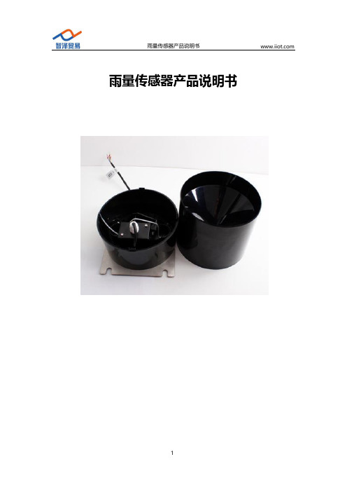
雨量传感器产品说明书目录1.产品简介 (4)1.1产品概述 (4)1.2功能特点 (4)2.参数详情 (5)2.1外形尺寸图 (5)2.2基本参数 (5)2.3通讯协议 (6)2.3.1通讯基本参数 (6)2.3.2数据帧格式定义 (6)2.3.3寄存器地址 (7)2.3.4通讯协议示例以及解释 (7)3.安装使用 (11)3.1系统架构图 (11)3.1.1直接接电脑或者PLC (11)3.1.2网络传输使用 (13)3.2接口说明 (13)3.3协议调试(只适用于485输出型) (14)3.3.1使用上位机测试 (14)3.3.2使用串口调试助手调试 (15)4.配置连接透传云平台 (18)4.1485型传感器使用有线DTU连接透传云 (18)4.1.1透传云设置 (18)1.注册透传云 (18)2.新增并配置模板及数据点 (19)3.新增设备 (20)4.1.2硬件连接 (21)4.1.3软件配置 (21)4.2485型传感器使用无线DTU连接透传云 (24)4.2.1硬件连接 (24)4.2.2软件配置 (24)4.3模拟量传感器使用RTU连接透传云平台 (27)4.3.1硬件连接 (27)4.3.2软件配置 (27)4.4设备联调 (32)5.包装售后 (34)5.1产品包装清单 (34)5.2联系方式 (34)5.3质保与售后 (35)5.4免责声明 (35)1.产品简介1.1产品概述雨量传感器,外型小巧轻便,便于携带和组装,用于测量自然界降雨量,同时将降雨量转换为以开关量形式表示的数字信息量输出,以满足信息传输、处理、记录和显示等的需要。
可用于气象台(站)、水文站、农林、国防、野外测报站等有关部门,配合我公司自主研发生产的雨量记录仪来测量降水量、降水强度、降水时间等。
可为防洪、供水调度、电站水库水情管理提供原始数据。
1.2功能特点•感光探头灵敏度高•信号稳定,精度高•测量范围宽、线形度好•防水性能好、使用方便•便于安装、传输距离远等2.参数详情2.1外形尺寸图2.2基本参数参数技术指标测量范围≤30mm/min 测量精度0.2mm供电电源12V-24VDC 工作温度-30℃-80℃工作湿度0%RH-80%RH 响应时间<2s耗电<1W2.3通讯协议2.3.1通讯基本参数参数内容设备地址1通讯协议MODBUS RTU编码8位二进制数据位8位奇偶校验位无停止位1位错误校准CRC冗长循环码波特率出厂默认为9600bps可设置2400bps、4800bps、9600bps 2.3.2数据帧格式定义采用Modbus-RTU通讯规约,格式如下:初始结构≥4字节的时间地址码=1字节功能码=1字节数据区=N字节错误校验=16位CRC码结束结构≥4字节的时间地址码:具体地址,在通讯网络中是唯一的(出厂默认0x01)。
感应式压力传感器70CP系列产品说明说明书

70CP SERIES | CERAMIC CAPACITIVE PRESSURE SENSOR6 to 30 VDC Supply, 4 to 20 mA or Voltage Output PERFORMANCE CHARACTERISTICSFeaturesDescriptionApplications• Enhanced accuracy over wide operating range • Housing options are compatible with most media • EMC protection to 100 V/m• Broad operating temperature range (-40°C to 135°C)• Exceptional shake and vibration tolerance • Overvoltage and reverse polarity protection • Small size and simple installationThe 70CP series pressure sensors are ideally suited for environmentally demanding OEM industrial applications. This series accommodates a wide range of input voltages (6 to 30 VDC) and provides several output options, including 4 to 20 mA. Housed in stainless steel, plated steel or brass, the 70CP series offers performance and economy.Sensata Technologies has been a leading global supplier of pressure sensors and switches for over 50 years.• Compressors & pumps • Hydraulics & pneumatics• Agriculture & construction equipment • Transportation & off-road vehicles • Engine controls & monitors • Alternative energy management • Load management• Process control & automation • Medical• MilitaryDimensions in mm [Inch]DIMENSIONAL DRAWINGS (71CP03 & 77CP02)V OLTAGET ERMINALINCHES [MM]MAXORDERING OPTIONSStainless Steel, 1/8” NPTF-2A Male, Packard Metri-Pack™, Vented Gage, Flourosilicone,4 to 20 mA, Required for Air and Water Application= NoneC = Required for Air and Water ApplicationsSeal Compatibility GuidePage 4Sensata Technologies, Inc. (“Sensata”) data sheets are solely intended to assist designers (“Buyers”) who are developing systems that incorporate Sensata products (also referred to herein as “components”). Buyer understands and agrees that Buyer remains responsible for using its independent analysis, evaluation and judgment in designing Buyer’s systems and products. Sensata data sheets have been created using standard laboratory conditions and engineering practices. Sensata has not conducted any testing other than that specifically described in the published documentation for a particular data sheet. Sensata may make corrections, enhancements, improvements and other changes to its data sheets or components without notice.Buyers are authorized to use Sensata data sheets with the Sensata component(s) identified in each particular data sheet. HOWEVER, NO OTHER LICENSE, EXPRESS OR IMPLIED, BY ESTOPPEL OR OTHERWISE TO ANY OTHER SENSATA INTELLECTUAL PROPERTY RIGHT, AND NO LICENSE TO ANY THIRD PARTY TECHNOLOGY OR INTELLECTUAL PROPERTY RIGHT, IS GRANTED HEREIN. SENSATA DATA SHEETS ARE PROVIDED “AS IS”. SENSATA MAKES NO WARRANTIES OR REPRESENTATIONS WITH REGARD TO THE DATA SHEETS OR USE OF THE DATA SHEETS, EXPRESS, IMPLIED OR STATUTORY, INCLUDING ACCURACY OR COMPLETENESS. SENSATA DISCLAIMSANY WARRANTY OF TITLE AND ANY IMPLIED WARRANTIES OF MERCHANTABILITY, FITNESS FOR A PARTICULAR PURPOSE, QUIET ENJOYMENT, QUIET POSSESSION, AND NON-INFRINGEMENT OF ANY THIRD PARTY INTELLECTUAL PROPERTY RIGHTS WITH REGARD TO SENSATA DATA SHEETS OR USE THEREOF.All products are sold subject to Sensata’s terms and conditions of sale supplied at SENSATA ASSUMES NO LIABILITY FOR APPLICATIONS ASSISTANCE OR THE DESIGN OF BUYERS’ PRODUCTS. BUYER ACKNOWLEDGES AND AGREES THAT IT IS SOLELY RESPONSIBLE FOR COMPLIANCE WITH ALL LEGAL, REGULATORY AND SAFETY-RELATED REQUIREMENTS CONCERNING ITS PRODUCTS, AND ANY USE OF SENSATA COMPONENTS IN ITS APPLICATIONS, NOTWITHSTANDING ANY APPLICATIONS-RELATED INFORMATION OR SUPPORT THAT MAY BE PROVIDED BY SENSATA.CONTACT USRevised 02/06/18Americas+1 (800) 350 2727***************************************Europe, Middle East & Africa+359 (2) 809 1826****************************Asia Pacific*************************.comChina +86 (21) 2306 1500Japan +81 (45) 277 7117Korea +82 (31) 601 2004India +91 (80) 67920890Rest of Asia +886 (2) 27602006ext 2808。
智能红外二氧化碳传感器(MH-711A)产品说明书

Intelligent Infrared CO2 Gas Sensor(Model: MH-711A)ManualVersion: 3.3Valid from: May 1st, 2014 Zhengzhou Winsen Electronics Technology Co., Ltd.StatementThis manual copyright belongs to Zhengzhou Winsen Electronics Technology Co., LTD. Without the written permission, any part of this manual shall not be copied, translated, stored in database or retrieval system, also can’t spread through electronic, copying, record ways.Thanks for purchasing our product. In order to keep customers using it better and reduce the faults caused by misuse, please read the manual carefully and operate it correctly in accordance with the instructions. If users disobey the terms or remove, disassemble, change the components inside of the sensor, we shall not be responsible for the loss.The specific such as color, appearance, sizes etc., please in kind prevail.We are devoting ourselves to products development and technical innovation, so we reserve the right to improve the products without notice. Please confirm it is the valid version before using this manual. At the same time, users’ comments on optimized using way are welcome.Please keep the manual properly, in order to get help if you have questions during the usage in the future.Zhengzhou Winsen Electronics Technology CO., LTD.MH-711A Infrared CO2 Gas Sensor1. Product DescriptionMH-711A is a universal type intelligent sensor to detect CO2 in air taking advantages of non-dispersive infrared (NDIR) principle. With high selectivity, no oxygen dependence, high performance and long lifespan features, MH-711A also has built-in temperature compensation feature. MH-711A is a compact andhigh-performance sensor based on infrared absorption of gas detection technology, micro-machining and sophisticated circuit design.2. CharacteristicsLong lifespanHigh Sensitivity and resolution5V constant power supply, low power consumption Output method: UART, analog voltage signal, etc. Quick response & ResumeTemperature compensation, excellent linear outputAnti-poisons, anti-vapor interferenceDetect combustible gas concentration matching with flame-proof marked detector in area 1&2explosive environments which mix of ⅡA, ⅡB, ⅡC and T1-T6 flammable gases, vapors and air3. ApplicationWidely used for industrial field instrumentation, industrial-process control and safety protection4. Technical ParametersProduct Model MH-711A Target Gas CO2 Working Voltage 4.5 V ~ 5.5V DC Average Current < 100mA Interface Level 3.3VMeasurement Range 0~30%VOL optional (view table 2)Output Signal IIC 0.4-2V DC Warm-up Time 3min Response Time T 90 < 30s Working Temp. -40℃ ~ 70℃Working Humidity0 to 95%RH, Non-condensingDimension Φ44×61mm Weight 350g Lifespan >5 years Ex-marking Ex d ⅡC T6 GbProtected ClassIP65Table 1 Technical IndexTable 2: Measurement Range and Accuracy5. Structural DrawingFigure 1 Structural Drawing of SensorFigure 2: Pin DefinitionPin DescriptionPad1 Vin (input voltage 4.5V ~5.5V) Pad4 GNDPad5 Vout (0.4~2V) Pad2 IIC(SCL) clock Pad3IIC(SDA) dataDetected GasMeasurementRange AccuracyRemarksCarbon Dioxide (CO2 gas)0~2000ppm ±50ppm +/-5% readingTemperature compensation 0~6000ppmTemperature compensation 0~1%VOL Temperature compensation 0~3%VOL Temperature compensation 0~5%VOL Temperature compensation 0~10%VOL Temperature compensation 0-30%VOL±15% reading Temperature compensationReserved, do not connectPad6, Pad7, Pad8Pad10, Pad11, Pad12Table 3: Definition of Pin6. Application CircuitFigure 3 Application CircuitExplanations:6.1: Analogue Voltage OutputVoltage output range 0.4 to 2V, relatively stands for 0 to F.S.Pad1 connect with 5V supply, Pad4 connect with VSS and Pad5 connect with input side of ADC. Then warm-up the sensor, the Vout will show a voltage value which stands for the gas concentration. If the sensor malfunctions, the output voltage is 0V.Figure 4 Analogue Voltage Output6.2 Digital OutputPad1 connect with 5V supply, Pad4 connect with VSS.Customer’s CLK connects with sensor CLK; SDA connect sensor SDA.The detector can read the value of gas concentration directly through the IIC of the sensor (The pull-up resistor of user’s SCL and SDA signal lines must be less than 10k to ensure the normal work of the communication interface), no need to calculate the gas concentration.6.2.1 Communication ProtocolMH-711A is communicated through IIC bus. The module works basing IIC slave mode and can connects to external MCU,module address: 0x55, write operation address: 0xAA, read operation address: 0xAB. Every frame number data contains 10 bytes. Different host orders lead to different data and the last byte of data is the proof test value. The SCL clock frequency is recommend less than 10K.1) Device AddressAddress format: Highest seven digits are the module add of the sensor(0x55),the least significant digit is SDIR, 0 stand for Reading, 1 stand for Writing.Table 4: Address FormatIIC communicationWrite address: 0xAA, Read address: 0xAB 2) Bus DescriptionIIC interface protocol is a special bus signal protocol, is composed of 3 parts - Start(S), Stop(P) and binary data, asshown below.At start,SCL is high,SDA is at falling edge.Aftter that,send the slave add.After the seven add digits is the control read&write digits,choose the read&write operation as above picWhen the slave device recognizes the corresponding add information,it sends a responsive signal to main device and SDA is pulled down at the ninth clock cycle.At stop,SCL keeps high level,SDA is at rising edge.Figure 5 IIC Sequence Chart3) CommandEvery frame number data of IIC communication command contains 10 bytes. Different host orders lead to different data and the last byte of data is the proof test value. Table 5 Command List0x96 Gas Concentration 0xA0 Calibrate zero point (ZERO ) 0xAACalibrate span point (SPAN )A7 A6 A5 A4 A3 A2 A1 W/R1 0 1 0 1 0 1 0/1Gas Concentration Reading1 0x96 Gas Concentration ReadingSend0 1 2 3 4 5 6 7 8 9 Command -- -- -- -- -- -- -- --CheckCode 0x96 0x00 0x00 0x00 0x00 0x00 0x00 0x00 0x00 0x6AEXP. 96 00 00 00 00 00 00 00 00 6AReturn0 1 2 3 4 5 6 7 8 9 ModuleStatusHighDensityLowDensityHighRangeLowRangeCheckCodeEXP. ReturnGas concentration= high density *256 + low density Calibrate Zero1 0xA0 Gas Concentration ReadingSend0 1 2 3 4 5 6 7 8 9 Command-- -- -- -- -- -- -- --CheckCode 0xa0 0x00 0x00 0x00 0x00 0x00 0x00 0x00 0x00 0x60EXP. A0 00 00 00 00 00 00 00 00 60Return 0 1 2 3 4 5 6 7 8 9 -- -- -- -- -- -- -- -- ---- -- -- -- -- -- -- -- --EXP. No value returnCalibrate Span1 0xAA Gas Concentration ReadingSend0 1 2 3 4 5 6 7 8 9 CommandSPAN Value -- -- -- -- -- --CheckCode 0xaaHighByteLowByte0x00 0x00 0x00 0x00 0x00 0x00 0xbbEXP. AA 13 88 00 00 00 00 00 00 BB (Eg. calibrate 5000ppm, HEX:0x1388)Return 0 1 2 3 4 5 6 7 8 9 -- -- -- -- -- -- -- -- ---- -- -- -- -- -- -- -- --EXP. No value return6.2.2 Calibrate and CalculateThe checksum = (invert (byte0 +... + 8)) + 1For example, Gas Concentration ReadingCommand SentByte0 Byte1 Byte2 Byte3 Byte4 Byte5 Byte6 Byte7 Byte8 Byte9 Command - - - - - - - - CheckValue 0x96 0x00 0x00 0x00 0x00 0x00 0x00 0x00 0x00 0x6AA. Add all the bytes together except byte 00x96 + 0 + 0 + 0 + 0 + 0 + 0 + 0 + 0 = 0x96B. Get the value from step A, then invert it.0xff – 0x96 = 0x69C. Plus one based on the value of step B0x69 + 0x01 = 0x6A6.2.3 Example ProgramC Language Calibrate & Calculate and Routinechar getCheckSum(char *packet){char i, checksum;for( i = 1; i < 9; i++){checksum += packet[i];}checksum = 0xff – checksum;checksum += 1;return checksum;}7. Notes For Maintenance7.1 The sensor should be calibrated regularly. Recommended cycle time is once per 6 months.7.2 Do not use the sensor in the high dusty environment for long time.7.3 Please use the sensor with correct power supply.Zhengzhou Winsen Electronics Technology Co., LtdAdd.: NO.299 Jinsuo Road, National Hi-Tech Zone,Zhengzhou, 450001 ChinaTel.: 0086-371-67169097Fax: 0086-371-60932988E-mail:*******************。
omega CN7500 温度传感器产品说明书

P-23配件(可在现场安装)* 可从cn.omega .com/cn7500下载免费CN7-A 软件订购示例:CN7523,双输出控制器,DC 脉冲和机械式继电器 RS485通讯功能。
CN7500系列温度/过程控制器的高级控制功能能够应对最艰巨的温度或过程应用。
CN7500控制器封装在紧凑型1⁄32 DIN 外壳中,它配备两个4位数字LED 显示屏,可在本地显示过程值和设定值。
控制方法有开/关、PID 、自动调谐和手动调谐。
64种温度和时间(斜坡/恒值)控制措施为PID 控制提供支持。
双回路输出控制允许同时进行加热和冷却。
可将第二个输出配置成使用13种内置报警功能中其中一种的报警模式。
RS485通讯功能为标配。
可提供多达247个通讯地址,传输速度达到2400 ~ 38,400 bps 。
其它功能包括通用输入、可选温度单位(°C/°F)、可选分辨率、高采样率以及安全保护功能。
U 两个4位数字LED 显示屏U 8个斜坡/恒值程序,每个程序8段U 通用输入信号U 自动调谐U 双控制输出U 标配RS485通讯功能U 具备报警功能U 提供免费软件CN7500系列1⁄32 DIN 斜坡/恒值 控制器规格输入:热电偶、RTD 、DC 电压或DC 电流显示屏:两个4位数字、7段式6.35 mm (25")高LED ; PV :红色 SV :绿色精度:量程的±0.25%,±1最低有效数位电源电压:100 ~ 240 Vac ,50/60 Hz 功耗:最大5 VA工作温度:0 ~ 50°C (32 ~ 122°F)备用存储器:非易失性存储器额定控制输出:继电器:SPST ,5A @ 250 Vac (电阻性) 电压脉冲:14 V ,10 ~ -20%(最大40 mA )电流:4 ~ 20 mA通讯:RS485 MODBUS ® A-5-11/RTU 通讯协议重量:114 g (4 oz)面板开孔:45 x 22.5 mm (1.772 x 0.886")最大面板厚度:3.40 mm (0.14")面板厚度:99.80 mm (3.86")。
温度_湿度_风速_风向传感器(RA0730_R72630_RA0730Y)使用说明书

温度_湿度_风速_风向传感器(RA0730_R72630_RA0730Y)使用说明书温度_湿度_风速_风向传感器说明书——适用型号:RA0730;RA0730Y;R72630Copyright©Netvox Technology Co.,Ltd.This document contains proprietary technical information which is the property of NETVOX Technology.It shall be maintained in strict confidence and shall not be disclosed to other parties,in whole or in part,without written permission of NETVOX Technology.The specifications are subject to change without prior notice.目录一、声明 (2)二、实物外观 (2)三、简介 (2)四、产品特性 (2)五、操作说明 (3)六、安装方法 (4)七、维护与保养 (6)一、声明在未经大洋事先书面许可的情况下,严禁以任何形式复制、传递、分发和存储本文档中的任何内容。
大洋遵循持续发展的策略。
因此,大洋保留在不预先通知的情况下,对本文档中描述的任何产品进行修改和改进的权利。
在任何情况下,大洋均不对任何数据或收入方面的损失,或任何特殊、偶然、附带或间接损失承担责任,无论该损失由何种原因引起。
本文档的内容按“现状”提供。
除非适用的法律另有规定,否则不对本文档的准确性、可靠性和内容做出任何类型的、明确或默许的保证,其中包括但不限于对适销性和对具体用途的适用性的保证。
大洋保留在不预先通知的情况下随时修订或收回本文档的权利。
二、实物外观R72630外观图(以实物为准)RA0730Y外观图(以实物为准)三、简介RA0730_R72630_RA0730Y为netvox基于LoRaWAN开放协议的ClassA类型设备,兼容LoRaWAN协议。
- 1、下载文档前请自行甄别文档内容的完整性,平台不提供额外的编辑、内容补充、找答案等附加服务。
- 2、"仅部分预览"的文档,不可在线预览部分如存在完整性等问题,可反馈申请退款(可完整预览的文档不适用该条件!)。
- 3、如文档侵犯您的权益,请联系客服反馈,我们会尽快为您处理(人工客服工作时间:9:00-18:30)。
1
转矩转速测量仪
目
录
开箱检查...............................................3 命名规则...............................................3 转矩测量基本原理...............................................3 转速测量基本原理 .............................................3 技术参数 .......................................................4 07 型传感器的安装 .........................................5
安装方法 1. 测量传感器的轴径和中心高,待装。 2. 使用两组联轴器,将传感器安装在动力设备与负载之间。 3. 分别调整动力设备、负载、传感器的中心高和同轴度,要求小于 0.05mm,然后将其固定,并紧固可靠,不允许有松动,使用小量程
转矩转速测量仪
或高转速传感器时,更要严格保证连接的中心高和同轴度。否则可 能造成测量误差及传感器的损坏。 4. 连接时可选用刚性或弹性联轴器,在震动较大或同轴度无法保证安
正向
转矩测量计算式
N
Mp=N (f-f0) / (fp-f0)
fr
0
f0 fp
Mr=N (f0-f) / (f0-fr)
-N
负向
Mp:正向转矩 N:转矩满量程 fP:正向满量程输出频率值(kHz) f:实测转矩输出频率值(kHz)
Mr:反向转矩 f0:转矩零点输出频率值(kHz) fr:反向满量程输出频率值(kHz)
特别注意
♦ 安装的环境要求:温度: -20℃~ 60℃ 湿度: <90%RH 无易燃、易爆物品
♦ 安装时切勿直接敲打、碰撞传感器。 ♦ 安装时禁止带电操作。 ♦ 此传感器为非防水、防爆设计,望使用时注意。 ♦ 避免强干扰,保证仪器的正常工作。 ♦ 传感器不能长时间过载使用,同时应避免过大的冲击载荷,否则可
传感器的安装必须由专业机械安装人员进行
4
07 型传感器的安装
①、ZH07-(空)、B 型外形结构及对应尺寸表
转矩转速测量仪
规格 Φb
(N.M) (J6)
ΦD
A
L
L1
H
h
E
B
C
F 键宽 标准转速
C 型键
b (r/min) (b×L×h×数量)
100 Φ18 Φ85 150 224 32 123 58 72 62 6.5 112 6 6000 6×32×6×2
3 4.5 51 107 50 18000~36000 3×16×3×2
5
4.5 51 107 50 16000~32000
5×23X5×2
100 Φ18 Φ75 210 30
142 72
6 6.5 58 117 62 11000~25000 6×28×6×2
200 Φ24 Φ85 242 42 150 72
衷心感谢您选用 ZH07 型系列
转矩转速测量仪
扭矩传感器!
ZH07 型系列扭矩传感器是本公司独立研制、生产的高科技 产品,请您在使用本产品之前,按您所选用产品的型号、规格, 仔细阅读本《使用说明书》,正确掌握本产品的安装和使用方 法。阅后请将本《使用说明书》妥善保管,以备今后进行检修 和维护时使用。
单位:mm
4200~8400
18×98×11×4
注:10 规格内包括:1Nm、2 Nm、3 Nm、5 Nm、10 Nm
50 规格内包括:20 Nm、30 Nm、40 Nm、50 Nm
100 规格内包括:60 Nm、70 Nm、80 Nm
6
③、ZH07-X 型外形结构及对应尺寸表
转矩转速测量仪
安装示意图
2
⌦ 开箱检查
转矩转速测量仪
开箱后,请先按《出货单》所列项目认真清点,确认箱内物品是否与《出 货单》一致,查看物品在运输过程中是否有破损现象,同时核对发货产品的 铭牌,确认产品的型号、规格及参数与您的订货要求一致。如有问题,请速 与我公司联系。
箱内物品:
①出货单 ⑤合格证
②传感器 ⑥平键
③航空插头 ⑦检定报告
单位:mm
注:100 牛.米内包括:10Nm;20 Nm;30 Nm;50 Nm
5
转矩转速测量仪
②、ZH07-G 型外形结构及对应尺寸表
规格 Φb
(N.M) (J6)
ΦD
L
L1
A
E
键宽
C
b
h
H
B
标准转速
(r/min)
C 型键
(b×L×h×数
量)
10 Φ10 Φ70 158 18 118 50 50 Φ14 Φ70 176 25 120 50
♦ 联机的测试电缆线应妥善固定好,防止旋转系统将其绞断。 ♦ 测试电缆线的航空插头处的屏蔽线接点不应随意拆除。 ♦ 测试电缆线的航空插头与传感器及仪表的航空插座应拧紧可靠。
9
转矩转速测量仪
⌦ 测量计算方法
在有效量程范围内,传感器的转矩输出频率与对应转矩值基本上成线性 关系,在具体应用中,如果测量准确度要求不超过标准值,不需要通过逐段 参数标定来完成计算。下图表示出转矩值与输出频率值的对应曲线,根据曲 线,同时列出了测量数据的计算公式:
89
72
82
8.5 210 20 2000 20×105×12×4
10000 Φ100 Φ182 180 447 130 244 122 80 112 10.5 230 28 2000 28×130×20×4
20000 Φ125 Φ230 216 506 140 295 150 100 140 12.5 253 32 1900 32×132×18×4
⌦ 技术参数
转矩准确度: 重复性: 过载能力: 滞后: 线性: 绝缘电阻: 工作温度: 相对湿度:
0.1~0.5% F·S 0.1~0.5% F·S 150%F.S 0.1~0.5% F·S 0.1~0.5% F·S ≥200MΩ -20~60℃ ≤90%RH
信号类型:
零转矩频率输出:
参考《检定报告》
正向转矩满量程频率输出*: 参考《检定报告》
反向转矩满量程频率输出*: 参考《检定报告》
转速不准确度: 60 个脉冲/转或 120 个脉冲/转(无积累误差)
信号输出为频率信号,幅值 5V 或 24V 可选
注:*确定正、反向转矩:将轴一端固定,另一端顺时针施加扭 力,确定为正向转矩;相反则为负向转矩。
1000 Φ48 Φ105 328 80
159 72 2-14 8.5
70 144 82
6000~12000
14×78×9×4
2000 Φ55 Φ125 385 105 167 72 2-16 8.5 74 162 82
5000~9600 16×103×10×4
3000 Φ65 Φ132 385 100 176 72 2-18 8.5 80 172 82
8 6.5 63 127 62 10000~21000 8×40×7×2
300 Φ28 Φ90 242 42
152 72
8 6.5 63 130 62 8500~18000
8×40×7×2
500 Φ38 Φ100 272 56
154 72 2-10 6.5
69 140 62
7000~13000
10×54×8×4
企业已通过 GJB9001B 及 ISO9001 认证
ZH07 型
转矩转速传感器
使用说明书
GB/T19001-2008
ISO9001:2008
北京中航科电测控技术有限公司
Beijing Zhonghang Kedian Measurement & Control Technolong Co.,Ltd
转速测量计算式
n=60f/Z
n:转速(r/min) f:实测转速输出频率值(kHz) Z:传感器测速盘齿数
10
转矩转速测量仪
未选用二次仪表时的使用方法
传感器用外接电源为其提供电源时,必须满足电流为 300mA ① 电压为±12V 的稳定直流电压时,
具体连接见航空插座的引线定义:
1 脚:地 2 脚:+12V 3 脚:-12V 4 脚:转速信号输出 5 脚:转矩信号输出
200 300
Φ28 Φ95 152 242
42
133
63
72
62
6.5 121 8
5000
8×40×7×2
500
700 Φ38 Φ105 154 272 57 144
69
72
62
6.5 136 10 4000 10×56×8×4
1000 Φ48 Φ115 156 328 82 150 70 72 82 8.5 165 14 3000 14×80×9×4
能造成弹性轴永久变形,无法回到测量零点。
8
⌦ 传感器与仪表的连接
转矩转速测量仪
1. 确保仪表电源关断。 2. 连接测试电缆线(按附图)。 3. 打开仪表电源开关即可工作(进入测量状态)。
附图 注:仪表使用请详细阅读 ZHK-D 转矩转速测量仪使用说明书。
特别注意
♦ 为了避免触电,应使用三芯电源线与三线式电源插座联接进行供电, 三线式电源插座的中心地线必须可靠接地。
1500
2000 Φ55 Φ125 168 385 105 161
74
72
82
8.5 198 16 2500 16×100×10×4
2500