超声波传感器使用说明
超声波传感器使用说明
超声波传感器使用说明1.电源接入:将超声波传感器的电源线与电源连接,确保电压稳定。
2.连接触发引脚和接收引脚:超声波传感器有一个触发引脚和一个接收引脚,触发引脚用于发送超声波脉冲,接收引脚用于接收反射波。
将传感器的触发引脚与控制器的IO口相连,接收引脚与控制器的IO口相连。
3.发射超声波脉冲:在控制器上设置触发引脚为高电平,保持一段时间后再下降到低电平。
高电平触发传感器发射超声波脉冲,可以通过设置触发时间来控制脉冲的持续时间,一般来说,脉冲持续时间越长,测量距离的精度越高。
4.接收反射波信号:超声波传感器发射的脉冲波会在物体上反射并返回,传感器接收到这个反射波信号后,触发引脚会发出一个低电平信号。
通过测量这个低电平信号的持续时间,可以计算出目标物体与传感器之间的距离。
一般可以通过控制器的计时器功能来测量这个时间。
5.计算距离:利用传感器发送和接收的时间差,结合超声波在空气中的传播速度,可以精确计算出目标物体与传感器之间的距离。
一般计算公式为:距离=时间差×速度,其中速度一般取340m/s。
6.转换为实际距离:有些超声波传感器会输出一个毫秒级的时间差值,需要根据传感器的数据手册来进行换算,将时间差转换为实际距离。
需要注意的是,超声波传感器对目标物体的性质有一定要求,例如传感器对于反射率较低的物体,如软质材料、液体、吸声材料等,测量距离的精度可能会降低。
此外,超声波传感器也有一定的应用注意事项,比如需要避免在多传感器密集布置的环境下使用,避免互相的干扰;要避免在含有较多尘埃、雾霾等粒子的环境中使用,以免影响测量结果;还要避免在强电磁辐射的环境下使用,以防止电磁辐射对传感器的工作性能产生干扰。
总结起来,超声波传感器的使用非常简单,只需连接电源、触发引脚和接收引脚、发送超声波脉冲,然后通过计算时间差来获取目标物体与传感器之间的距离。
在应用中,还要注意目标物体的特性和环境的影响,以获取准确的测量结果。
超声波传感器的使用说明书

超声波传感器的使用说明书
一、产品概述
超声波传感器是一种利用超声波原理进行测距的装置,具有测量准确、反应速度快、抗干扰能力强等特点。
本产品适用于各种需要进行距离测量的场合,如机器人避障、物体定位、液位监测等。
二、产品特点
1. 高精度测量:采用先进的超声波发射和接收技术,能够实现高精度的距离测量,误差率小于1%。
2. 快速反应:产品具有快速的信号处理速度和反应时间,能够在短时间内获取准确的测量结果。
3. 抗干扰能力强:采用特殊的信号处理技术,能够有效地减少电磁干扰、环境噪声等因素对测量结果的影响。
4. 易于安装:产品体积小,重量轻,易于安装和调试。
三、使用步骤
1. 安装传感器:将超声波传感器固定在需要测量的位置,确保传感器前方无遮挡物,并且传感器能够正常发射和接收超声波。
2. 连接电源:将超声波传感器的电源线连接到控制器或电源适配器上,确保电源稳定可靠。
3. 调试传感器:通过控制器或软件对超声波传感器进行参数设置和
调试,确保测量结果准确可靠。
4. 读取数据:通过控制器或软件读取超声波传感器的测量数据,根据需要进行数据处理和分析。
四、注意事项
1. 避免在高温、高湿度、高粉尘等恶劣环境下使用传感器。
2. 在安装传感器时,应避免在传感器前方放置金属等反射物,以免影响测量结果。
3. 在调试传感器时,应按照说明书上的参数进行设置,不要随意更改参数。
4. 在读取数据时,应确保连接可靠,不要随意断开连接。
超声波物位计使用说明书
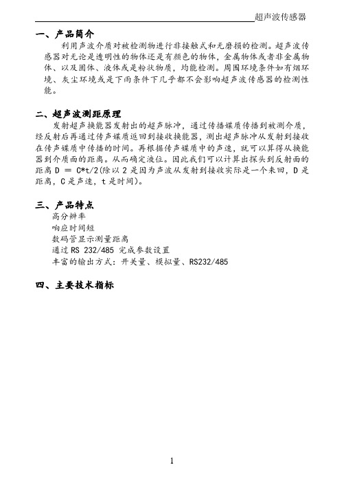
超声波传感器一、产品简介利用声波介质对被检测物进行非接触式和无磨损的检测。
超声波传感器对无论是透明性的物体还是有颜色的物体,金属物体或者非金属物体、以及固体、液体或是粉状物质,均能检测。
周围环境条件如有烟环境、灰尘环境或是下雨条件下几乎都不会影响超声波传感器的检测性能。
二、超声波测距原理发射超声换能器发射出的超声脉冲,通过传播媒质传播到被测介质,经反射后再通过传声媒质返回到接收换能器,测出超声脉冲从发射到接收在传声媒质中传播的时间。
再根据传声媒质中的声速,就可以算得从换能器到介质面的距离。
从而确定液位。
因此我们可以计算出探头到反射面的距离D = C*t/2(除以2是因为声波从发射到接收实际是一个来回,D是距离,C是声速,t是时间)。
三、产品特点高分辨率响应时间短数码管显示测量距离通过RS 232/485 完成参数设置丰富的输出方式:开关量、模拟量、RS232/485四、主要技术指标你五、安装指南5.1 安装注意事项(1)超声波传感器安装时发射面应垂直于被测物体; (2)电源线和输出信号线不要接反。
5.2安装尺寸⑴ 超声波传感器外形图:HFTCGQ_SMG 型:(2)超声波传感器尺寸图 HFTCGQ_SMG 型:功 能 一体型量 程 0.05~0.5m 0.1~1m 0.2~3m 0.2~4m 0.3~5m 0.3~6m探头频率200K 100K 65K 65K 50K 50K安装尺寸HFTCGQ_SMG 型 M60*1.5M18*1.5M27*1.5 M40*1.5 M40*1.5 M40*1.5M40*1.5分辨率 3mm 或0.1%(取大者) 响应时间 < 200ms显 示 LED , 数码管 发射角度 20°模拟输出 4~20mA/500Ω负载、0~5V开关量输出 继电器DC 30V/ 5A 、PNP/NPN (5V )(可选) RS232/485 MODBUS 协议或者厂家自定义协议(可选) 供 电 标配24V (±15%) 环境温度 -20~+60℃, 防护等级IP65 可选IP67超声波传感器5.3 实物安装HFTCGQ_SMG型:①在被测物体上方装一个法兰②法兰上放一片内径相同的垫片③把测距传感器对准法兰孔④将测距传感器放入法兰孔⑤从法兰底部看到的情况⑥法兰下放一片内径相同的垫片你⑦拧上螺母固定好测距传感器⑧给测距传感器接上电缆线HFTCGQ_ZL型:(停产)①在被测物体上方装一个法兰②把测距传感器对准并放入法兰孔③拧上螺母固定好测距传感器④给测距传感器接上探头线超声波传感器⑤给测距传感器接上电缆线5.4 接线方式电源:红线: 24VDC+ 黑线: 24VDC–1、4~20mA:蓝线: mA + 黄线: mA–2、0~5V:蓝线: V + 黄线: V–3、485/232通讯:黄线:T/R+ 蓝线: T/R–4、继电器信号:蓝线黄线你5、NPN信号:蓝线:NPN+ 黄线:NPN -6、PNP信号:蓝线:PNP+ 黄线:PNP-备注:1、输出信号选择(1~6)其中一种;2、要将黑线可靠接地;3、当测距传感器为mA模块时,也可将黄线(mA-)接地;六、信号说明HFTCGQ_SMG型:初始上电时,电源指示灯“绿灯”常亮。
DS-808HDR 存在式超声波感应器说明书

3.探测器光学视区示意图如下: Side view
2.7m
0.0m
4
3
21
0
1
2
3
4
TOP-VIEW 5 4 3 2 1 0 1 2 3 4 5 (m)
5 4 3 2 1 0 1 2 3 4 5
1
4.超声灵敏度调节: 可调电阻设置为最大时,超声探测器距离为 4 米, 如果减少超声探测距离, 通过调节超声可调电阻 至适当位置并测试。
5.红外灵敏度调节 可调电阻设置为最大时,红外探测器距离为 4 米, 如果减少红外探测距离, 可调节红外可调电阻 至适当位置并测试。
6.探测器延时调节: 每当检测到移动时,在预设时间内保持激活状态, 通过调节延迟关闭时间设置预设时间;逆时针旋 能 转到最小值为 5 秒,顺时针旋转到最大值为 10 分 钟;如果在打开期间检测到移动,从最近检测到 移动之后保持激活状态,直到延迟关闭时间结束。
7.光感功能调节: 当 B1 设置为 OFF,启动光敏功能,根据环境设定需要调节 旋钮更改设置值;当 B1 设置为 ON,在测试模式下,该功
失效;可调电阻设置为最大时,在环境光较亮测试时, 探测器探测后输出并打开照明设备;如需将探测器设置 在较暗的环境时,可调节光感值到适当的位置并测试。
8.功能设置表格如下 :
启状态;当两种技术均未检测到移动,则在延迟关闭时间结束后关闭照明设备。 双鉴模式 2: 开关 A1(OFF),A2(OFF):在该模式下, 当 HDIR™红外检测到移动时打开照明设备。然后任何一种技
术检测到移动时将使照明设备保持开启状态;当两种技术均未检测到移动时,则在延迟关闭时间结束 后关闭照明设备。 单红外模式: 开关 A1(ON),A2(OFF): 在该模式下, HDIR™红外检测到移动时,则打开照明设备并保持开启状态; 当该技术未检测到移动时,则在延迟关闭时间结束后关闭照明设备。 单超声模式:开关 A1(ON),A2(ON): 在该模式下,超声检测到移动时,则打开照明设备并保持开启状态。当该技术 未检测到移动时,则在延迟关闭时间结束后关闭照明设备。 测试模式: 产品通过拨码开关 B3 设置 OFF ON 0FF 进去测试模式,该模式下输出延迟关闭时间为 5 秒,且 每隔 3 秒闪烁 1 次。进入该模式 15 分钟后产品退出测试模式回到正常延迟关闭设定时间。 LED 功能: 感应器内部设有两个 LED 指示灯, 当检测到移动时,它们将闪烁;拨码开关 B2 可设置 LED 灯亮/ 灭,红色 LED 闪烁表示红外技术检测到移动,绿色 LED 闪烁表示超声技术检测到移动。
超声波传感器的使用方法和测距准确度

超声波传感器的使用方法和测距准确度超声波传感器是一种常用的测距设备,它利用了声波在空气中传播的特性来测量距离。
在工业自动化、智能家居和机器人等领域,超声波传感器被广泛应用。
本文将介绍超声波传感器的使用方法和测距准确度,以帮助读者更好地了解和应用这种传感技术。
一、超声波传感器的工作原理超声波传感器通过发射超声波脉冲并接收反射回来的声波来测量距离。
其工作原理基于声波在空气中传播的速度是已知的,因此可以通过测量声波的往返时间来计算距离。
传感器的发射器发射超声波脉冲,然后等待接收到反射波的时间,通过测量时间间隔就可以得到距离。
二、超声波传感器的使用方法超声波传感器的使用非常简单,只需连接至相应的电路和控制器。
在测距前,用户需要进行以下几个步骤:1. 确定适当的超声波传感器型号:超声波传感器有多种不同型号和规格可供选择,因此用户需要根据实际需求选择适合的型号。
一般来说,传感器的功耗、测距范围和精度是需要考虑的重要因素。
2. 连接电源和信号线:超声波传感器通常需要接入电源和信号线,以便传输测距数据和控制信号。
用户需要根据传感器的规格和要求,正确连接相应的线缆。
3. 安装传感器:根据实际应用场景,用户需要将超声波传感器正确安装在测距的目标物体附近。
要保证传感器与目标物体之间没有遮挡物,以充分发挥传感器的功能。
4. 数据采集和处理:连接超声波传感器后,用户可以通过相应的控制器或电路板来采集和处理传感器输出的数据。
一般情况下,用户可以将测距数据用数字设备进行显示或存储,也可以通过编程实现更复杂的功能。
三、超声波传感器的测距准确度超声波传感器的测距准确度是使用者非常关注的一个重要指标。
其测距准确度主要受到以下几个因素的影响:1. 传感器频率:超声波传感器的频率决定了其测距能力的上限。
一般来说,频率越高,传感器的测距精度越高。
但是高频的传感器通常功耗也较高,因此需要根据实际需求权衡测距范围和功耗。
2. 目标物体的特性:不同的目标物体对超声波的反射能力不同,这也会影响传感器的测距准确度。
技术资料:Turbimax CUS71D 超声波污泥界面传感器说明书

Products Solutions Services TI00490C/28/ZH/04.15技术资料Turbimax CUS71D超声波污泥界面传感器浸入式传感器,用于污泥界面测量应用在许多工艺过程中,沉淀后的悬浮液将分离成固液两相。
为了确保过程的经济性和高效性, 必须连续监测沉降和沉淀过程中出现的分离层和过渡层的分层界面。
Turbimax CUS71D传感器广泛应用于污泥界面测量:•污水处理:初沉池、污泥浓缩池、二沉池•水净化:添加絮凝剂后的沉淀池、监测过滤介质膨胀,优化反冲洗操作、污泥接触处理过程中污泥泥位•行业:静态分离过程优势•提供两种不同类型的传感器,择优选择,满足测量任务的要求•带预定义计算单元,调试简单•智能传感器:传感器内储存了所有特征参数值和标定参数值Turbimax CUS71D2Endress+Hauser功能与系统设计测量原理压电晶体安装在平头柱体塑料外壳内。
经电压激励后的压电晶体发出声纳信号。
超声波信号以657 kHz 频率、6°发射角扫描分离层。
被测参数为超声波信号的运行时间,即到达分离层的固体颗粒至返回接收器的时间。
带刮刷的传感器可以防止传感器覆膜上生成粘污。
功能声速随着测量介质物理属性的变化而变化,受温度和大气压的影响。
同时,也会随着液相层和介质中的悬浮固体浓度的变化而变化。
为了获取精准的测量结果,使系统变量适应过程条件(例如:脉冲宽度和声速)十分重要。
CM44x 具有下列信号评估功能:•屏蔽非期望的分离层•评估不同的回波信号强度•选择评估中的主、从信号边缘•以不同倍数放大传感器信号,例如:悬浮污泥测量•确定分离层的上、下高度区间值,仅在指定高度偏差范围内进行信号评估。
区间值在分离层周围移动。
因此,无需采用算术方法平滑测量值传感器监控连续监测光学信号,并进行测量值的合理性检查。
出现差值时,变送器发出故障信息。
Liquiline CM44x 变送器的传感器检测系统可以检测下列故障:•出现不合理的高或低测量值•错误测量值导致的控制紊乱传感器连接•Liquiline CM442变送器:仅允许连接一个超声波污泥界面传感器。
超声波传感器数据手册说明书

DatasheetUltrasonic Sensors with TEACH-Mode Programming•Fast, easy-to-use TEACH-Mode programming; no potentiometer adjustments•Program both outputs together or independently, with either an upward or a downward analogoutput slope•Remote TEACH for security and convenience•Choose models with 150 mm to 1 m range (5.9 in to 39.4 in) or 300 mm to 2 m range (11.8 in to78.7 in)•Wide operating range of –20 °C to +70 °C (–4 °F to +158 °F)•Choose models with NPN or PNP discrete output, plus 0 to 10V dc or 4 to 20 mA sourcing analogoutput•LED indicators for Power ON/OFF; Signal Strength; and Analog/Discrete Outputs Conducting•Choose models with integral unterminated 2 m (6.5 ft) or 9 m (30 ft) cable, or with M12/Euro-stylequick-disconnect connection•Compact, self-contained sensor package•Rugged design for use in demanding sensing environments; rated IEC IP67, NEMA 6PWARNING:•Do not use this device for personnel protection•Using this device for personnel protection could result in serious injury or death.•This device does not include the self-checking redundant circuitry necessary to allow its use in personnel safety applications. A device failure or malfunction can cause either an energized (on) or de-energized (off) output condition.Models—Proximity ModeOverviewThe U-GAGE is an easy-to-use ultrasonic sensor, ideal for demanding environments. Simple push-button programming provides flexibility for a variety of applications. Excellent for measurement applications such as sensing of liquid levels in a tank or, for example, determining box heights for sorting purposes.Each sensor includes both an analog and a discrete output, which may be programmed independently with different window limits or together with identical limits. Each output has the option of being set with a sensing distance set point centered within a 10-mm window.U-GAGE® T30 Series with Analog and DiscreteOutputsFeatures and IndicatorsU-GAGE Figure 1. U-GAGE T30 Series sensor programming push buttons and indicatorsNote: All LED indicators momentarily turn off when the sensor changes state between Program and Run modes.The U-GAGE sensor has four LED indicators. The red Signal LED indicates the strength and condition of the sensor's incoming signal. Each amberOutput LED, whether analog or discrete, turns on when a target is sensed within the programmed window limits. The green Power ON/OFF LED indicates the operating status of the sensor. There are two modes of indication for the LED indicators: Run Mode and Program Mode.In Run mode:In Program mode:WiringNPN*It is recommended that the shield wire be connected to either earth ground or DC common.–+ PNP*It is recommended that the shield wire be connected to either earth ground or DC common.–+Cabled wiring diagrams are shown. Quick disconnect wiring diagrams are functionally identical.Configuring a Sensor Window LimitsWindow limits can be taught to the sensor in several ways, using either the push buttons on the back of the sensor or remote input.Note: When the sensor changes state between PROGRAM and RUN modes, all of the LED indicators turn OFF momentarily,before the appropriate LEDs come ON as described below. The sensing window limits expand temporarily to full scale (max range) during PROGRAM mode.Remote InputTo program the sensor remotely or to disable the keypad, use the Remote Programming function. In addition to programming the sensor, use the remote input to disable the buttons for security, preventing unauthorized or accidental programming changes. Connect the gray wire of the sensor to +12 V dc to 24 V dc, with a remote programming switch connected between them.Note: The impedance of the remote teach input is 55 kΩ.Programming is accomplished by following the sequence of input pulses. The duration of each pulse (corresponding to a push button “click”), and the period between multiple pulses, are defined as: 0.04 seconds < T < 0.8 seconds.Note: To exit PROGRAM mode without saving any changes, hold the Remote line high > 2 seconds (before teaching the second limit). The sensor reverts to the last saved program.LimitOutput 2 Limits OnlyLimitLimitPush Button Locked out(or Enabled)Output 1Limits OnlyLimit Both OutputsTogetherPush ButtonLockout (or Enable)0.04 sec < T < 0.8 secFigure 2. Timing programs for remote TEACH programmingGeneral Notes on Configuration•The sensor returns to Run mode if the first TEACH condition is not registered within 120 seconds.•After the first limit is taught, the sensor remains in Program mode until the TEACH sequence is finished.•To exit PROGRAM mode without saving any changes, press and hold the programming push button > 2 seconds or hold the Remote line high > 2 seconds (before teaching the second limit). The sensor reverts to the last saved program.Configuring Limits for Either Analog or Discrete OutputNote: To exit PROGRAM mode without saving any changes, press and hold the programming push button > 2 seconds or hold the Remote line high > 2 seconds (before teaching the second limit). The sensor reverts to the last saved program.1.Choose the output for the first set of window limits (analog or discrete).2.Configure the first limit.3.Teach the second limit.4.Repeat for the other output (analog or discrete) if a second output is desired.Configure Analog or Discrete Limits Using the Auto-Zero FeatureFor some applications, a sensing distance set point centered within a minimum sensing window may be required. The TEACH procedure for this application is simple: configuring the same limit twice causes the sensor to program a 10-mm window centered on the position taught (position ±5mm).Note: The sensor allows for some forgiveness in this procedure. If the two limits are not exactly the same (but closer than the minimum 10-mm window required), the sensor places the set point at the average of the two limits.Configuring Identical Limits for Both Analog and Discrete Outputs SimultaneouslyTo set both the analog and the discrete outputs at exactly the same limits, both may be set simultaneously.1.Enter PROGRAM mode.2.Configure the first limit.3.Teach the second limit.Push Button LockoutAnalog OutputThe U-GAGE T30 Series series sensor may be configured for either a positive or a negative output slope, based on which condition is taught first (see Figure 3 on page 6). If the near limit is taught first, the slope is positive; if the far limit is taught first, the slope is negative. Banner’s scalable analog output automatically distributes the output signal over the width of the programmed sensing window.The U-GAGE T30 Series also features a 2-second hold upon loss of the received analog signal, which is useful for harsh and unstable applications.In the event of analog signal loss for longer than 2 seconds, the analog output goes to 3.6 mA or 0 V dc, which may be used to trigger an alarm.Current-Sourcing Models Target Position Positive SlopeNear WindowFar WindowA n a l o g O u t p u t (m A )204Negative SlopeVoltage-Sourcing ModelsTarget PositionPositive SlopeNearWindowFar WindowV o l t a g e O u t p u t (V d c )100Negative SlopeFigure 3. Positive and Negative Output SlopesNote: The analog current output tracks slightly past each window limit (from 3.8 to 20.5 mA).Self-Diagnostic Error ModeIn the unlikely event of a microprocessor memory error, all of the LEDs will flash in sequence. If this occurs, the setup parameters have been lost and the sensor may be corrupt. Contact Banner Engineering for further information.SpecificationsProximity Mode RangeA suffix models: 150 mm (5.9 in) minimum near limit; 1 m (39 in) maximum far limitB suffix models: 300 mm (11.8 in) minimum near limit; 2 m (79 in) maximum far limit Supply VoltageCurrent-sourcing analog output models: 12 V dc to 24 V dc (10% maximum ripple) at 90 mA, exclusive of loadVoltage-sourcing analog output models: 15 V dc to 24V dc (10% maximum ripple) at 90 mA, exclusive of load Supply Protection CircuitryProtected against reverse polarity and transient voltages Output ConfigurationsDiscrete (switched) output: SPST solid-state switch conducts when target is sensed within sensing window; choose NPN or PNP modelsAnalog output: Choose 0 V dc to 10 V dc sourcing or 4 mA to 20 mA sourcing output models; output slope may be selected via TEACH sequence (see Window Limits on page 3)Output RatingsDiscrete (switched) output: 100 mA maximumOff-state leakage current: less than 5 microampsOn-state saturation voltage: less than 1 V at 10 mA and less than 1.5 V at 100 mA Analog output:Voltage sourcing: 0 V dc to 10 V dc (at 1K Ω minimum resistance)Current sourcing: 4 to 20 mA, 1 Ω to Rmax Rmax = V supply - 7V / 20 mA Output Protection CircuitryProtected against output short-circuit, continuous overload, transient overvoltages,and false pulse on power-up Output Response Time Discrete output:“A” suffix models: 48 milliseconds “B” suffix models: 96 milliseconds Analog output:“A” suffix models: 48 milliseconds average, 16-millisecond update “B”suffix models: 96 milliseconds average, 32-millisecond update ConstructionMolded reinforced thermoplastic polyester housingSensing PerformanceNote: Specified using a 10 cm × 10 cm aluminum target at 25 ºC under fixed sensing conditions.Analog sensing resolution: ±0.25% of measured distance Analog linearity: ±0.5% of full-scale sensing range Sensing repeatability: ±0.25% of distance Minimum window size: 10 mm (0.4 in)Hysteresis of discrete output: 2.5 mm (0.10 in)AdjustmentsSensing window limits (analog or discrete): TEACH-mode programming of near and far window limits may be set using the push buttons on the sensor or remotely via TEACH input (see Configuring a Sensor on page 3). Discrete and analog window limits may be programmed separately, or together.Analog output slope: the first limit taught is assigned to the minimum output value (4mA or 0V)Environmental RatingLeakproof design is rated IEC IP67; NEMA 6P Connections2 m (6.5 ft) or 9 m (30 ft) 5-conductor PVC-covered attached cable, or 5-pin Euro-style quick-disconnect fitting Operating ConditionsTemperature: –20 °C to +70 °C (–4 °F to +158 °F)100% maximum relative humidity Application NotesObjects passing inside the specified near limit will produce a false response.Note: For more information about out-of-range and signal loss response of the analog output, see Analog Output on page 5.Vibration and Mechanical ShockAll models meet MIL-STD-202F, Method 201A (Vibration: 10 Hz to 60 Hz maximum,0.06 inch (1.52 mm) double amplitude, 10G maximum acceleration) requirements. Also meets IEC 60947-5-2 (Shock: 30G 11 ms duration, half sine wave) requirements.CertificationsDimensionsM30 x 1.5ThreadQuick-Disconnect ModelsPerformance Curves00200 mm (8.0 in)400 mm (16.0 in)600 mm (24.0 in)800 mm (32.0 in)1000 mm (40.0 in)50501001001501502002002.0 in 2.0 in 4.0 in4.0 in 6.0 in 6.0 in8.0 in 8.0 in DISTANCEW I D T H (m m )Figure 4. A Models 00400 mm (16.0 in)800 mm (32.0 in)1200 mm (48.0 in)1600 mm (64.0 in)2000 mm (80.0 in)10010020020030030040040004.0 in 4.0 in 8.0 in 8.0 in 12.0 in 12.0 in16.0 in 16.0 inDISTANCEWI D T H (m m )Figure 5. B Models05050100100150150200200(8.0 in)(16.0 in)(24.0 in)(32.0 in)(40.0 in)2.0 in 2.0 in 4.0 in4.0 in 6.0 in 6.0 in8.0 in 8.0 in DISTANCE W I D T H (m m )Figure 6. A Models 010*******200300300400400DISTANCE400 mm (16.0 in)800 mm (32.0 in)1200 mm (48.0 in)1600 mm (64.0 in)2000 mm (80.0 in)04.0 in 4.0 in 8.0 in 8.0 in 12.0 in12.0 in16.0 in 16.0 inW I D T H (m m )Figure 7. B ModelsAccessories CordsetsBracketsAll measurements are in mm.Banner Engineering Corp. Limited WarrantyBanner Engineering Corp. warrants its products to be free from defects in material and workmanship for one year following the date of shipment. Banner Engineering Corp. will repair or replace, free of charge, any product of its manufacture which, at the time it is returned to the factory, is found to have been defective during the warranty period. This warranty does not cover damage or liability for misuse, abuse, or the improper application or installation of the Banner product.THIS LIMITED WARRANTY IS EXCLUSIVE AND IN LIEU OF ALL OTHER WARRANTIES WHETHER EXPRESS OR IMPLIED (INCLUDING, WITHOUT LIMITATION, ANY WARRANTY OF MERCHANTABILITY OR FITNESS FOR A PARTICULAR PURPOSE), AND WHETHER ARISING UNDER COURSE OF PERFORMANCE, COURSE OF DEALING OR TRADE USAGE.This Warranty is exclusive and limited to repair or, at the discretion of Banner Engineering Corp., replacement. IN NO EVENT SHALL BANNER ENGINEERING CORP. BE LIABLE TO BUYER OR ANY OTHER PERSON OR ENTITY FOR ANY EXTRA COSTS, EXPENSES, LOSSES, LOSS OF PROFITS, OR ANY INCIDENTAL, CONSEQUENTIAL OR SPECIAL DAMAGES RESULTING FROM ANY PRODUCT DEFECT OR FROM THE USE OR INABILITY TO USE THE PRODUCT, WHETHER ARISING IN CONTRACT OR WARRANTY, STATUTE, TORT, STRICT LIABILITY, NEGLIGENCE, OR OTHERWISE.Banner Engineering Corp. reserves the right to change, modify or improve the design of the product without assuming any obligations or liabilities relating to any product previously manufactured by Banner Engineering Corp. Any misuse, abuse, or improper application or installation of this product or use of the product for personal protection applications when the product is identified as not intended for such purposes will void the product warranty. Any modifications to this product without prior express approval by Banner Engineering Corp will void the product warranties. All specifications published in this document are subject to change; Banner reserves the right to modify product specifications or update documentation at any time. Specifications and product information in English supersede that which is provided in any other language. For the most recent version of any documentation, refer to: .For patent information, see /patents.。
超声波传感器产品说明说明书

ApplicationThe sensor measures the spectral absorption of process liquids in the ultraviolet region of the electromagnetic spectrum.•Measurement of protein concentrations •Chromatography monitoring •Filtration monitoring •Concentration measurement of organic compounds •Detection of aromatesYour benefits•Improved process control and easier quality control thanks to quick and reliable monitoring of product concentration –Measuring range up to 2.5 AU or 50 OD (depending on optical path length)–Measurement of UV absorption at discrete wavelengths between 254 nm and 313 nm –Outstanding filter properties for highest linearity –Direct concurrence with laboratory values –Integrated reference detector for lamp compensation –Gas discharge lamp for long service life and stable measured values •FM- and ATEX-approved lamps for applications in the hazardous area •Compliance with life sciences sector thanks to hygienic design and FDA- and USP-compliant sealing materials •High degree of product safety as SIP/CIP-resistant •High product yield thanks to low volume requirements •Maximum durability in all applications owing to wide range of materials and process connections •Can be adapted to process requirements:Optional air purge ports to prevent the formation of condensate on the optical windowsProducts Solutions ServicesTechnical Information OUSAF46Optical sensor with the OUA260 flow assembly for the measurement of UV absorptionTI01190C/07/EN/02.1771388454OUSAF462Endress+HauserFunction and system designMeasuring principle Light absorption The measuring principle is based on the Lambert-Beer law.There is a linear dependency between the absorption of light and the concentration of the absorbing substance:A = -log(T) = ε . c . OPL T = I/I 0T ... Transmission I ... Intensity of received light at detector I 0 ... Intensity of transmitted light of light source A ... Absorption ε ... Extinction coefficient c ... Concentration OPL ... Optical path lengthA light source emits radiation through the medium and the incident radiation is measured on the detector side.The subsequent conversion to absorbance units (AU, OD) is performed in the associated transmitter.1Absorption measurement with reference 1Light source 2Optical windows 3Measurement filter 4Measuring detector 5Lens 6Medium flow 7Reference filter 8Reference detectorOUSAF46 has 2 pairs of reference and measuring detectors (= 2 channels). Only one channel is shown for the sake of simplicity.Measuring system An optical measuring system comprises:•Sensor (photometer) OUSAF46•Transmitter, for example Liquiline CM44P •Cable set, for example CUK80•Assembly OUA260OUSAF46Endress+Hauser 32Example of a measuring system with a photometer sensor 1pipe 5Flow assembly OUA2602Transmitter CM44P 6Sensor: light source (lamp)3CUK80 cable set 7CUK80 cable set 4Sensor: detector InputMeasured variableUV-absorption Measuring range •0 to 2.5 AU •Max. 50 OD (depending on the optical path length)WavelengthDiscrete wavelength at 254, 280, 295 or 313 nm Power supplyElectrical connection The sensor is connected to the transmitter using the pre-terminated or labeled cable set CUK80 (for connection to CM44P) or OUK (for connection to CVM40) . The terminals and labeling may vary depending on the transmitter in use. The cable set must be ordered separately.OUSAF464Endress+Hauser3OUSAF46 connecting cable ALight source (lamp) power supply B Signals of measurement and reference detectorCable lengthMaximum 100 m (330 ft)Lamp voltage Versions for use inhazardous areas 1)Safety instructions for electrical apparatus in explosion-hazardous areas, XA01403CConnecting the detector using a safety barrierThe photometer sensors use silicon photovoltaic cells as detectors which are operated in the current mode. The detectors are intrinsically safe and can be deployed in Zone 1 and Class I, Division 1environments.1)Applies only to measuring points consisting of a photometer, CUK80 cable set and Liquiline CM44P transmitter.OUSAF46Endress+Hauser 5The safe area is separated from the hazardous area by safety barrier MTL7760AC.4Safety barrier, dimensions in mm (inch)The safety barrier may only have a very low leak current since the optical signals from the sensor can be in the nanoampere range. Therefore, the sensor cable shield is connected to the ground terminal of the barrier.On delivery, the CUK80 detector cable is permanently wired to the . All you have to do is simply connect the individual cable ends to the detector and transmitter.Connecting the hazardous area lamp using a junction boxThe hazardous area lamp (EXP-1) must be connected to the transmitter using a certified junction box.For versions with FM approval, the junction box is included in the delivery and already pre-terminated on the lamp side. You simply have to connect the cable of the transmitter (CUK80)to the terminals of the junction box.For versions with ATEX approval, the junction box is not included in the delivery and it and the cable glands required must be provided by the customer at the place of installation. You must connect the cables entirely on your own (CUK80 of transmitter and lamp cable of photometer sensor).OUSAF466Endress+HauserInstallation5Mounting angles. The arrows indicate the direction of medium flow in the pipe.ASuitable mounting angle, better than C BOptimum mounting angle, best installation position CAcceptable mounting angle DMounting angle to be avoided E Forbidden mounting angleEnvironmentAmbient temperature0 to 55 °C (32 to 130 °F)Storage temperature-10 to +70 °C (+10 to +160 °F)Humidity5 to 95 %Degree of protection IP 65 (NEMA 4) for all optical partsProcessProcess temperature 0 to 90 °C (32 to 194 °F) continuousMax. 130 °C (266 °F) for 2 hoursProcess pressure Max. 100 bar (1450 psi) absolute, depending on the material, pipe size and process connection of the flow assemblyOUSAF46Endress+Hauser 7Mechanical construction6Sensor module ADimension of lamp → Table BDimension of detector → Table C Assembly, see Technical Information for assembly The total length of the sensor module is derived from the lengths of the lamp, the detector and the assembly.The dimensions of the OUA260 assembly are provided in Technical Information, TI00418C.‣Allow an additional gap of 5 cm (2") on both the lamp side and detector side of the sensor to connect the sensor cable.Weight SensorUV lamp0.58 kg (1.28 lbs)UV lamp with wire-braided cable (1.2 m (4 ft)) and junction box (sensor for hazardous area)3.2 kg (6.66 lbs)Easycal detector0.53 kg (1.17 lbs)Standard detector0.78 kg (1.71 lbs)Materials Sensor housingStainless steel 316Assembly OUA260Stainless steel 316, 316L or Kynar Cable connector endsNickel-plated brass Light sourceLow-pressure mercury lampLamp operating life: typically 3000 hDetectorUV silicon detector, hermetically sealed Filter Multilayer interference filter, designed for extreme UV conditionsOUSAF468Endress+HauserCertificates and approvalsmark Declaration of ConformityThe product meets the requirements of the harmonized European standards. As such, it complies with the legal specifications of the EU directives. The manufacturer confirms successful testing of the product by affixing to it the mark.Ex approvals •ATEX II 2G Ex db IIC T5 Gb •FM Cl.1, Div. 1, Groups B, C, DFDA conformityAll non-metal parts in contact with medium, such as rubber and plastic parts, meet the requirements of FDA 21 CFR 177.2600. The plastic and elastomer parts of the sensor in contact with medium have passed the biological reactivity tests according to USP <87> and <88> Class VI.Ordering informationProduct page /ousaf46Product Configurator On the product page there is a "Configure" button to the right of the product image Configure .1.Click this button. The Configurator opens in a separate window.2.Select all the options to configure the device in line with your requirements. In this way, you receive a valid and complete order code for the device.3.Export the order code as a PDF or Excel file. To do so, click the appropriate button on the rightabove the selection window.For many products you also have the option of downloading CAD or 2D drawings of the selected product version. Click the tab for this CAD and select the desired file type using picklists.Scope of delivery The scope of delivery consists of the following :•Detector and lamp module without flow assembly or •Detector and lamp module mounted on flow assembly •Operating InstructionsOrdering the sensor together with a transmitter:If you select the calibration option in the Product Configurator for the transmitter , the complete measuring system (transmitter, sensor, cable) is factory-calibrated and shipped as one package.‣If you have any queries:Please contact your supplier or local sales center.AccessoriesThe following are the most important accessories available at the time this documentation was issued.‣For accessories not listed here, please contact your Service or Sales Center.OUSAF46Endress+Hauser 9Flow assembly OUA260•Flow assembly for hygienic sensors •For sensor installation in pipes •Materials: stainless steel 316, 316L or Kynar (other materials available on request)•Wide variety of process connections and path lengths available •Product Configurator on the product page:/oua260Technical Information TI00418CCable CUK80 cable set •Pre-terminated and labeled cables for connecting analog photometer sensors •Product Configurator on the product page: /cuk80CalibrationKit OUSAF46 EasyCal retrofit kit •Patented system traceable to NIST for the calibration of UV absorption sensors •Order numbers:–254 nm: 71210149–280 nm: 71210150–295 nm: 71210156–313 nm: 71210151Reference rod Order number: 71108543。
- 1、下载文档前请自行甄别文档内容的完整性,平台不提供额外的编辑、内容补充、找答案等附加服务。
- 2、"仅部分预览"的文档,不可在线预览部分如存在完整性等问题,可反馈申请退款(可完整预览的文档不适用该条件!)。
- 3、如文档侵犯您的权益,请联系客服反馈,我们会尽快为您处理(人工客服工作时间:9:00-18:30)。
超声波测距模块使用说明
班级:13电信A 组员:曾俊雄王铭
一、主要技术参数:
1:工作电压:DC5V
2:静态电流:小于2mA
3:电平输出:高5V
4:电平输出:底0V
5:感应角度:不大于15 度
6:感应距离:4cm-5 米
7:高精度:0.3cm
板上接线为如右图(左数起):
1:VCC 、2:trig(控制端)、3:echo(接收端)、4:out(空脚)、5:GND
4 脚为此模块作为防盗模块时的开关量输出脚,测距模块不用此脚!
二、本产品使用方法:
1、将模块的1脚连接到TX-1C开发板的VCC。
2、将模块的2脚连接到TX-1C开发板的P2.5。
3、将模块的3脚连接到TX-1C开发板的P2.4。
4、将模块的5脚连接到TX-1C开发板的GND。
5、下载程序即可利用超声波模块测距了。
注意:测距时模块的4脚悬空即可。
实验要求:
1、用串口监视器显示超声波测距的距离
2、用LCD1602显示超声波测距的距离
3、我们连接的实验电路
4、
程序
#include <LiquidCrystal.h>
LiquidCrystal lcd(12, 11,5,4,3,2);
const int TrigPin = 6;
const int EchoPin = 7;
float distance;
void setup()
{
pinMode(TrigPin, OUTPUT);
pinMode(EchoPin, INPUT);
lcd.begin(16,2);
}
void loop()
{
digitalWrite(TrigPin, LOW);
delayMicroseconds(2);
digitalWrite(TrigPin, HIGH);
delayMicroseconds(10);
digitalWrite(TrigPin, LOW);
distance = pulseIn(EchoPin, HIGH) / 58.00;
lcd.setCursor(0,0);
lcd.print("distance");
lcd.setCursor(6,1);
lcd.print(distance);
lcd.print(" CM");
delay(1000);
}
三、实验心得体会
这次实训使用超声波传感器,让我学会了简单超声波传感器操作,希望下次能有机会再次进行实训。