超声波传感器使用说明
超声波传感器使用说明
超声波传感器使用说明1.电源接入:将超声波传感器的电源线与电源连接,确保电压稳定。
2.连接触发引脚和接收引脚:超声波传感器有一个触发引脚和一个接收引脚,触发引脚用于发送超声波脉冲,接收引脚用于接收反射波。
将传感器的触发引脚与控制器的IO口相连,接收引脚与控制器的IO口相连。
3.发射超声波脉冲:在控制器上设置触发引脚为高电平,保持一段时间后再下降到低电平。
高电平触发传感器发射超声波脉冲,可以通过设置触发时间来控制脉冲的持续时间,一般来说,脉冲持续时间越长,测量距离的精度越高。
4.接收反射波信号:超声波传感器发射的脉冲波会在物体上反射并返回,传感器接收到这个反射波信号后,触发引脚会发出一个低电平信号。
通过测量这个低电平信号的持续时间,可以计算出目标物体与传感器之间的距离。
一般可以通过控制器的计时器功能来测量这个时间。
5.计算距离:利用传感器发送和接收的时间差,结合超声波在空气中的传播速度,可以精确计算出目标物体与传感器之间的距离。
一般计算公式为:距离=时间差×速度,其中速度一般取340m/s。
6.转换为实际距离:有些超声波传感器会输出一个毫秒级的时间差值,需要根据传感器的数据手册来进行换算,将时间差转换为实际距离。
需要注意的是,超声波传感器对目标物体的性质有一定要求,例如传感器对于反射率较低的物体,如软质材料、液体、吸声材料等,测量距离的精度可能会降低。
此外,超声波传感器也有一定的应用注意事项,比如需要避免在多传感器密集布置的环境下使用,避免互相的干扰;要避免在含有较多尘埃、雾霾等粒子的环境中使用,以免影响测量结果;还要避免在强电磁辐射的环境下使用,以防止电磁辐射对传感器的工作性能产生干扰。
总结起来,超声波传感器的使用非常简单,只需连接电源、触发引脚和接收引脚、发送超声波脉冲,然后通过计算时间差来获取目标物体与传感器之间的距离。
在应用中,还要注意目标物体的特性和环境的影响,以获取准确的测量结果。
超声波传感器的使用说明书

超声波传感器的使用说明书
一、产品概述
超声波传感器是一种利用超声波原理进行测距的装置,具有测量准确、反应速度快、抗干扰能力强等特点。
本产品适用于各种需要进行距离测量的场合,如机器人避障、物体定位、液位监测等。
二、产品特点
1. 高精度测量:采用先进的超声波发射和接收技术,能够实现高精度的距离测量,误差率小于1%。
2. 快速反应:产品具有快速的信号处理速度和反应时间,能够在短时间内获取准确的测量结果。
3. 抗干扰能力强:采用特殊的信号处理技术,能够有效地减少电磁干扰、环境噪声等因素对测量结果的影响。
4. 易于安装:产品体积小,重量轻,易于安装和调试。
三、使用步骤
1. 安装传感器:将超声波传感器固定在需要测量的位置,确保传感器前方无遮挡物,并且传感器能够正常发射和接收超声波。
2. 连接电源:将超声波传感器的电源线连接到控制器或电源适配器上,确保电源稳定可靠。
3. 调试传感器:通过控制器或软件对超声波传感器进行参数设置和
调试,确保测量结果准确可靠。
4. 读取数据:通过控制器或软件读取超声波传感器的测量数据,根据需要进行数据处理和分析。
四、注意事项
1. 避免在高温、高湿度、高粉尘等恶劣环境下使用传感器。
2. 在安装传感器时,应避免在传感器前方放置金属等反射物,以免影响测量结果。
3. 在调试传感器时,应按照说明书上的参数进行设置,不要随意更改参数。
4. 在读取数据时,应确保连接可靠,不要随意断开连接。
超声传感器 UA30CAD60说明书
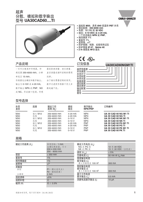
超声分散、模拟和数字输出型号 UA30CAD60....TI• 圆柱形 M30,具有 Ø40 前盖和 PBT 外壳• 感应距离:350-6000 mm • 电源:12 (15) 到 30 VDC • 输出:0-10 VDC 或 4-20 mA , 一个开关输出 NPN 或 PNP 。
• 线性错误 1%• 重复性 1%• 波束角。
±7°• 防护措施:短路、反极性和过压• 防护等级 IP 67,Nema 4X • 2 m 线缆或 M12 插头产品说明一系列分散超声传感器,传感范围 350-6000 mm ,分辨率低至 15 mm 。
传感器包含模拟和数字输出。
输出为 0-10V 或 4-20 mA ,数字输出 NPN 或 PNP 、NO 或 NC ,形成窗口检测。
传感器是距离测量、液位测量、直径测量或循环控制的理想选择。
由于微处理器控制的使用,数字过滤使传感器不受大多数电磁干扰。
型号选择外壳 连接额定工作 模拟 数字输出 订购编号直径 距离 (S n ) 输出 NPN /PNP M30 插头 M12 350-6000 mm 4-20 mA NPN UA 30 CAD 60 NG M1 TI M30 线缆350-6000 mm 4-20 mA NPN UA 30 CAD 60 NG TI M30 插头 M12 350-6000 mm 0-10 V NPN UA 30 CAD 60 NK M1 TI M30 线缆350-6000 mm 0-10 V NPN UA 30 CAD 60 NK TI M30 插头 M12 350-6000 mm 4-20 mA PNP UA 30 CAD 60 PG M1 TI M30 线缆350-6000 mm 4-20 mA PNP UA 30 CAD 60 PG TI M30 插头 M12 350-6000 mm 0-10 V PNP UA 30 CAD 60 PK M1 TI M30线缆350-6000 mm0-10 VPNPUA 30 CAD 60 PK TI规格UA30CAD60..规格(续)检测范围布线图UA30CAD60..89.859.6103Ø 40M 30 x 1.5 - 6g尺寸编程设置感测点 P1(最长距离)和最短距离 (P2) 的常规设置与传感器类型或功能无关。
DS-808HDR 存在式超声波感应器说明书

3.探测器光学视区示意图如下: Side view
2.7m
0.0m
4
3
21
0
1
2
3
4
TOP-VIEW 5 4 3 2 1 0 1 2 3 4 5 (m)
5 4 3 2 1 0 1 2 3 4 5
1
4.超声灵敏度调节: 可调电阻设置为最大时,超声探测器距离为 4 米, 如果减少超声探测距离, 通过调节超声可调电阻 至适当位置并测试。
5.红外灵敏度调节 可调电阻设置为最大时,红外探测器距离为 4 米, 如果减少红外探测距离, 可调节红外可调电阻 至适当位置并测试。
6.探测器延时调节: 每当检测到移动时,在预设时间内保持激活状态, 通过调节延迟关闭时间设置预设时间;逆时针旋 能 转到最小值为 5 秒,顺时针旋转到最大值为 10 分 钟;如果在打开期间检测到移动,从最近检测到 移动之后保持激活状态,直到延迟关闭时间结束。
7.光感功能调节: 当 B1 设置为 OFF,启动光敏功能,根据环境设定需要调节 旋钮更改设置值;当 B1 设置为 ON,在测试模式下,该功
失效;可调电阻设置为最大时,在环境光较亮测试时, 探测器探测后输出并打开照明设备;如需将探测器设置 在较暗的环境时,可调节光感值到适当的位置并测试。
8.功能设置表格如下 :
启状态;当两种技术均未检测到移动,则在延迟关闭时间结束后关闭照明设备。 双鉴模式 2: 开关 A1(OFF),A2(OFF):在该模式下, 当 HDIR™红外检测到移动时打开照明设备。然后任何一种技
术检测到移动时将使照明设备保持开启状态;当两种技术均未检测到移动时,则在延迟关闭时间结束 后关闭照明设备。 单红外模式: 开关 A1(ON),A2(OFF): 在该模式下, HDIR™红外检测到移动时,则打开照明设备并保持开启状态; 当该技术未检测到移动时,则在延迟关闭时间结束后关闭照明设备。 单超声模式:开关 A1(ON),A2(ON): 在该模式下,超声检测到移动时,则打开照明设备并保持开启状态。当该技术 未检测到移动时,则在延迟关闭时间结束后关闭照明设备。 测试模式: 产品通过拨码开关 B3 设置 OFF ON 0FF 进去测试模式,该模式下输出延迟关闭时间为 5 秒,且 每隔 3 秒闪烁 1 次。进入该模式 15 分钟后产品退出测试模式回到正常延迟关闭设定时间。 LED 功能: 感应器内部设有两个 LED 指示灯, 当检测到移动时,它们将闪烁;拨码开关 B2 可设置 LED 灯亮/ 灭,红色 LED 闪烁表示红外技术检测到移动,绿色 LED 闪烁表示超声技术检测到移动。
超声波传感器的使用方法和测距准确度

超声波传感器的使用方法和测距准确度超声波传感器是一种常用的测距设备,它利用了声波在空气中传播的特性来测量距离。
在工业自动化、智能家居和机器人等领域,超声波传感器被广泛应用。
本文将介绍超声波传感器的使用方法和测距准确度,以帮助读者更好地了解和应用这种传感技术。
一、超声波传感器的工作原理超声波传感器通过发射超声波脉冲并接收反射回来的声波来测量距离。
其工作原理基于声波在空气中传播的速度是已知的,因此可以通过测量声波的往返时间来计算距离。
传感器的发射器发射超声波脉冲,然后等待接收到反射波的时间,通过测量时间间隔就可以得到距离。
二、超声波传感器的使用方法超声波传感器的使用非常简单,只需连接至相应的电路和控制器。
在测距前,用户需要进行以下几个步骤:1. 确定适当的超声波传感器型号:超声波传感器有多种不同型号和规格可供选择,因此用户需要根据实际需求选择适合的型号。
一般来说,传感器的功耗、测距范围和精度是需要考虑的重要因素。
2. 连接电源和信号线:超声波传感器通常需要接入电源和信号线,以便传输测距数据和控制信号。
用户需要根据传感器的规格和要求,正确连接相应的线缆。
3. 安装传感器:根据实际应用场景,用户需要将超声波传感器正确安装在测距的目标物体附近。
要保证传感器与目标物体之间没有遮挡物,以充分发挥传感器的功能。
4. 数据采集和处理:连接超声波传感器后,用户可以通过相应的控制器或电路板来采集和处理传感器输出的数据。
一般情况下,用户可以将测距数据用数字设备进行显示或存储,也可以通过编程实现更复杂的功能。
三、超声波传感器的测距准确度超声波传感器的测距准确度是使用者非常关注的一个重要指标。
其测距准确度主要受到以下几个因素的影响:1. 传感器频率:超声波传感器的频率决定了其测距能力的上限。
一般来说,频率越高,传感器的测距精度越高。
但是高频的传感器通常功耗也较高,因此需要根据实际需求权衡测距范围和功耗。
2. 目标物体的特性:不同的目标物体对超声波的反射能力不同,这也会影响传感器的测距准确度。
技术资料:Turbimax CUS71D 超声波污泥界面传感器说明书

Products Solutions Services TI00490C/28/ZH/04.15技术资料Turbimax CUS71D超声波污泥界面传感器浸入式传感器,用于污泥界面测量应用在许多工艺过程中,沉淀后的悬浮液将分离成固液两相。
为了确保过程的经济性和高效性, 必须连续监测沉降和沉淀过程中出现的分离层和过渡层的分层界面。
Turbimax CUS71D传感器广泛应用于污泥界面测量:•污水处理:初沉池、污泥浓缩池、二沉池•水净化:添加絮凝剂后的沉淀池、监测过滤介质膨胀,优化反冲洗操作、污泥接触处理过程中污泥泥位•行业:静态分离过程优势•提供两种不同类型的传感器,择优选择,满足测量任务的要求•带预定义计算单元,调试简单•智能传感器:传感器内储存了所有特征参数值和标定参数值Turbimax CUS71D2Endress+Hauser功能与系统设计测量原理压电晶体安装在平头柱体塑料外壳内。
经电压激励后的压电晶体发出声纳信号。
超声波信号以657 kHz 频率、6°发射角扫描分离层。
被测参数为超声波信号的运行时间,即到达分离层的固体颗粒至返回接收器的时间。
带刮刷的传感器可以防止传感器覆膜上生成粘污。
功能声速随着测量介质物理属性的变化而变化,受温度和大气压的影响。
同时,也会随着液相层和介质中的悬浮固体浓度的变化而变化。
为了获取精准的测量结果,使系统变量适应过程条件(例如:脉冲宽度和声速)十分重要。
CM44x 具有下列信号评估功能:•屏蔽非期望的分离层•评估不同的回波信号强度•选择评估中的主、从信号边缘•以不同倍数放大传感器信号,例如:悬浮污泥测量•确定分离层的上、下高度区间值,仅在指定高度偏差范围内进行信号评估。
区间值在分离层周围移动。
因此,无需采用算术方法平滑测量值传感器监控连续监测光学信号,并进行测量值的合理性检查。
出现差值时,变送器发出故障信息。
Liquiline CM44x 变送器的传感器检测系统可以检测下列故障:•出现不合理的高或低测量值•错误测量值导致的控制紊乱传感器连接•Liquiline CM442变送器:仅允许连接一个超声波污泥界面传感器。
倍加福 超声波传感器 UC2000-30GM-E6R2-V15 手册

ḋᴀݙᆍᬍᯊᘩϡ䗮ⶹ
Copyright Pepperl+Fuchs, Printed in Germany
2
超声波传感器
LED 显示 运行状态
开关点 A1 设置 检测到目标 未检测到目标 开关点 A2 设置 检测到目标 未检测到目标 输出模式设置 (E2/E3) 开关点模式 窗口模式 迟滞模式 正常工作模式 温度补偿 设定插头拔出或短接 干扰 (如:压缩空气) 待机模式 LED 灯亮指示开关输出闭合
UC2000-30GM-E6R2-V15
双 LED 红 色 黄色 LED A1
绿
LED
黄色 LED A2
闪
暗
闪
暗
暗
闪
闪
暗
闪
暗
暗
闪
暗
闪
暗
闪
亮
暗
闪
暗
亮
暗
暗
闪
亮
暗
闪
闪
亮
暗
开关状态 A1
开关状态 A2
暗
亮
开关状态 A1
开关状态 A2
暗
闪
上次或规定状态 上次或规定状态
闪
暗
先前状态
先前状态
LED-ش੨
LED !!!!ࣜ
A 1 (N.O.) ਸ࠲ 1
A 2 (N.O.) ਸ࠲ 2
ਸ࠲ ۅ1
ړA1 > A2 ้LjघऄྺԿ
ਸ࠲ ۅ2
A 1 (N.C.) ਸ࠲ 1
A2 (N.C.) ਸ࠲ 2 2. ش੨ఇ๕ A1,A2ᅜࢻ࣑
A 1 (N.O.) ਸ࠲ 1
如果在同步输入端加上大于 1 s 的高电平,传感器进入待机模式(绿色指示灯)。输 出停止在最后的状态。
超声波传感器数据手册说明书

DatasheetUltrasonic Sensors with TEACH-Mode Programming•Fast, easy-to-use TEACH-Mode programming; no potentiometer adjustments•Program both outputs together or independently, with either an upward or a downward analogoutput slope•Remote TEACH for security and convenience•Choose models with 150 mm to 1 m range (5.9 in to 39.4 in) or 300 mm to 2 m range (11.8 in to78.7 in)•Wide operating range of –20 °C to +70 °C (–4 °F to +158 °F)•Choose models with NPN or PNP discrete output, plus 0 to 10V dc or 4 to 20 mA sourcing analogoutput•LED indicators for Power ON/OFF; Signal Strength; and Analog/Discrete Outputs Conducting•Choose models with integral unterminated 2 m (6.5 ft) or 9 m (30 ft) cable, or with M12/Euro-stylequick-disconnect connection•Compact, self-contained sensor package•Rugged design for use in demanding sensing environments; rated IEC IP67, NEMA 6PWARNING:•Do not use this device for personnel protection•Using this device for personnel protection could result in serious injury or death.•This device does not include the self-checking redundant circuitry necessary to allow its use in personnel safety applications. A device failure or malfunction can cause either an energized (on) or de-energized (off) output condition.Models—Proximity ModeOverviewThe U-GAGE is an easy-to-use ultrasonic sensor, ideal for demanding environments. Simple push-button programming provides flexibility for a variety of applications. Excellent for measurement applications such as sensing of liquid levels in a tank or, for example, determining box heights for sorting purposes.Each sensor includes both an analog and a discrete output, which may be programmed independently with different window limits or together with identical limits. Each output has the option of being set with a sensing distance set point centered within a 10-mm window.U-GAGE® T30 Series with Analog and DiscreteOutputsFeatures and IndicatorsU-GAGE Figure 1. U-GAGE T30 Series sensor programming push buttons and indicatorsNote: All LED indicators momentarily turn off when the sensor changes state between Program and Run modes.The U-GAGE sensor has four LED indicators. The red Signal LED indicates the strength and condition of the sensor's incoming signal. Each amberOutput LED, whether analog or discrete, turns on when a target is sensed within the programmed window limits. The green Power ON/OFF LED indicates the operating status of the sensor. There are two modes of indication for the LED indicators: Run Mode and Program Mode.In Run mode:In Program mode:WiringNPN*It is recommended that the shield wire be connected to either earth ground or DC common.–+ PNP*It is recommended that the shield wire be connected to either earth ground or DC common.–+Cabled wiring diagrams are shown. Quick disconnect wiring diagrams are functionally identical.Configuring a Sensor Window LimitsWindow limits can be taught to the sensor in several ways, using either the push buttons on the back of the sensor or remote input.Note: When the sensor changes state between PROGRAM and RUN modes, all of the LED indicators turn OFF momentarily,before the appropriate LEDs come ON as described below. The sensing window limits expand temporarily to full scale (max range) during PROGRAM mode.Remote InputTo program the sensor remotely or to disable the keypad, use the Remote Programming function. In addition to programming the sensor, use the remote input to disable the buttons for security, preventing unauthorized or accidental programming changes. Connect the gray wire of the sensor to +12 V dc to 24 V dc, with a remote programming switch connected between them.Note: The impedance of the remote teach input is 55 kΩ.Programming is accomplished by following the sequence of input pulses. The duration of each pulse (corresponding to a push button “click”), and the period between multiple pulses, are defined as: 0.04 seconds < T < 0.8 seconds.Note: To exit PROGRAM mode without saving any changes, hold the Remote line high > 2 seconds (before teaching the second limit). The sensor reverts to the last saved program.LimitOutput 2 Limits OnlyLimitLimitPush Button Locked out(or Enabled)Output 1Limits OnlyLimit Both OutputsTogetherPush ButtonLockout (or Enable)0.04 sec < T < 0.8 secFigure 2. Timing programs for remote TEACH programmingGeneral Notes on Configuration•The sensor returns to Run mode if the first TEACH condition is not registered within 120 seconds.•After the first limit is taught, the sensor remains in Program mode until the TEACH sequence is finished.•To exit PROGRAM mode without saving any changes, press and hold the programming push button > 2 seconds or hold the Remote line high > 2 seconds (before teaching the second limit). The sensor reverts to the last saved program.Configuring Limits for Either Analog or Discrete OutputNote: To exit PROGRAM mode without saving any changes, press and hold the programming push button > 2 seconds or hold the Remote line high > 2 seconds (before teaching the second limit). The sensor reverts to the last saved program.1.Choose the output for the first set of window limits (analog or discrete).2.Configure the first limit.3.Teach the second limit.4.Repeat for the other output (analog or discrete) if a second output is desired.Configure Analog or Discrete Limits Using the Auto-Zero FeatureFor some applications, a sensing distance set point centered within a minimum sensing window may be required. The TEACH procedure for this application is simple: configuring the same limit twice causes the sensor to program a 10-mm window centered on the position taught (position ±5mm).Note: The sensor allows for some forgiveness in this procedure. If the two limits are not exactly the same (but closer than the minimum 10-mm window required), the sensor places the set point at the average of the two limits.Configuring Identical Limits for Both Analog and Discrete Outputs SimultaneouslyTo set both the analog and the discrete outputs at exactly the same limits, both may be set simultaneously.1.Enter PROGRAM mode.2.Configure the first limit.3.Teach the second limit.Push Button LockoutAnalog OutputThe U-GAGE T30 Series series sensor may be configured for either a positive or a negative output slope, based on which condition is taught first (see Figure 3 on page 6). If the near limit is taught first, the slope is positive; if the far limit is taught first, the slope is negative. Banner’s scalable analog output automatically distributes the output signal over the width of the programmed sensing window.The U-GAGE T30 Series also features a 2-second hold upon loss of the received analog signal, which is useful for harsh and unstable applications.In the event of analog signal loss for longer than 2 seconds, the analog output goes to 3.6 mA or 0 V dc, which may be used to trigger an alarm.Current-Sourcing Models Target Position Positive SlopeNear WindowFar WindowA n a l o g O u t p u t (m A )204Negative SlopeVoltage-Sourcing ModelsTarget PositionPositive SlopeNearWindowFar WindowV o l t a g e O u t p u t (V d c )100Negative SlopeFigure 3. Positive and Negative Output SlopesNote: The analog current output tracks slightly past each window limit (from 3.8 to 20.5 mA).Self-Diagnostic Error ModeIn the unlikely event of a microprocessor memory error, all of the LEDs will flash in sequence. If this occurs, the setup parameters have been lost and the sensor may be corrupt. Contact Banner Engineering for further information.SpecificationsProximity Mode RangeA suffix models: 150 mm (5.9 in) minimum near limit; 1 m (39 in) maximum far limitB suffix models: 300 mm (11.8 in) minimum near limit; 2 m (79 in) maximum far limit Supply VoltageCurrent-sourcing analog output models: 12 V dc to 24 V dc (10% maximum ripple) at 90 mA, exclusive of loadVoltage-sourcing analog output models: 15 V dc to 24V dc (10% maximum ripple) at 90 mA, exclusive of load Supply Protection CircuitryProtected against reverse polarity and transient voltages Output ConfigurationsDiscrete (switched) output: SPST solid-state switch conducts when target is sensed within sensing window; choose NPN or PNP modelsAnalog output: Choose 0 V dc to 10 V dc sourcing or 4 mA to 20 mA sourcing output models; output slope may be selected via TEACH sequence (see Window Limits on page 3)Output RatingsDiscrete (switched) output: 100 mA maximumOff-state leakage current: less than 5 microampsOn-state saturation voltage: less than 1 V at 10 mA and less than 1.5 V at 100 mA Analog output:Voltage sourcing: 0 V dc to 10 V dc (at 1K Ω minimum resistance)Current sourcing: 4 to 20 mA, 1 Ω to Rmax Rmax = V supply - 7V / 20 mA Output Protection CircuitryProtected against output short-circuit, continuous overload, transient overvoltages,and false pulse on power-up Output Response Time Discrete output:“A” suffix models: 48 milliseconds “B” suffix models: 96 milliseconds Analog output:“A” suffix models: 48 milliseconds average, 16-millisecond update “B”suffix models: 96 milliseconds average, 32-millisecond update ConstructionMolded reinforced thermoplastic polyester housingSensing PerformanceNote: Specified using a 10 cm × 10 cm aluminum target at 25 ºC under fixed sensing conditions.Analog sensing resolution: ±0.25% of measured distance Analog linearity: ±0.5% of full-scale sensing range Sensing repeatability: ±0.25% of distance Minimum window size: 10 mm (0.4 in)Hysteresis of discrete output: 2.5 mm (0.10 in)AdjustmentsSensing window limits (analog or discrete): TEACH-mode programming of near and far window limits may be set using the push buttons on the sensor or remotely via TEACH input (see Configuring a Sensor on page 3). Discrete and analog window limits may be programmed separately, or together.Analog output slope: the first limit taught is assigned to the minimum output value (4mA or 0V)Environmental RatingLeakproof design is rated IEC IP67; NEMA 6P Connections2 m (6.5 ft) or 9 m (30 ft) 5-conductor PVC-covered attached cable, or 5-pin Euro-style quick-disconnect fitting Operating ConditionsTemperature: –20 °C to +70 °C (–4 °F to +158 °F)100% maximum relative humidity Application NotesObjects passing inside the specified near limit will produce a false response.Note: For more information about out-of-range and signal loss response of the analog output, see Analog Output on page 5.Vibration and Mechanical ShockAll models meet MIL-STD-202F, Method 201A (Vibration: 10 Hz to 60 Hz maximum,0.06 inch (1.52 mm) double amplitude, 10G maximum acceleration) requirements. Also meets IEC 60947-5-2 (Shock: 30G 11 ms duration, half sine wave) requirements.CertificationsDimensionsM30 x 1.5ThreadQuick-Disconnect ModelsPerformance Curves00200 mm (8.0 in)400 mm (16.0 in)600 mm (24.0 in)800 mm (32.0 in)1000 mm (40.0 in)50501001001501502002002.0 in 2.0 in 4.0 in4.0 in 6.0 in 6.0 in8.0 in 8.0 in DISTANCEW I D T H (m m )Figure 4. A Models 00400 mm (16.0 in)800 mm (32.0 in)1200 mm (48.0 in)1600 mm (64.0 in)2000 mm (80.0 in)10010020020030030040040004.0 in 4.0 in 8.0 in 8.0 in 12.0 in 12.0 in16.0 in 16.0 inDISTANCEWI D T H (m m )Figure 5. B Models05050100100150150200200(8.0 in)(16.0 in)(24.0 in)(32.0 in)(40.0 in)2.0 in 2.0 in 4.0 in4.0 in 6.0 in 6.0 in8.0 in 8.0 in DISTANCE W I D T H (m m )Figure 6. A Models 010*******200300300400400DISTANCE400 mm (16.0 in)800 mm (32.0 in)1200 mm (48.0 in)1600 mm (64.0 in)2000 mm (80.0 in)04.0 in 4.0 in 8.0 in 8.0 in 12.0 in12.0 in16.0 in 16.0 inW I D T H (m m )Figure 7. B ModelsAccessories CordsetsBracketsAll measurements are in mm.Banner Engineering Corp. Limited WarrantyBanner Engineering Corp. warrants its products to be free from defects in material and workmanship for one year following the date of shipment. Banner Engineering Corp. will repair or replace, free of charge, any product of its manufacture which, at the time it is returned to the factory, is found to have been defective during the warranty period. This warranty does not cover damage or liability for misuse, abuse, or the improper application or installation of the Banner product.THIS LIMITED WARRANTY IS EXCLUSIVE AND IN LIEU OF ALL OTHER WARRANTIES WHETHER EXPRESS OR IMPLIED (INCLUDING, WITHOUT LIMITATION, ANY WARRANTY OF MERCHANTABILITY OR FITNESS FOR A PARTICULAR PURPOSE), AND WHETHER ARISING UNDER COURSE OF PERFORMANCE, COURSE OF DEALING OR TRADE USAGE.This Warranty is exclusive and limited to repair or, at the discretion of Banner Engineering Corp., replacement. IN NO EVENT SHALL BANNER ENGINEERING CORP. BE LIABLE TO BUYER OR ANY OTHER PERSON OR ENTITY FOR ANY EXTRA COSTS, EXPENSES, LOSSES, LOSS OF PROFITS, OR ANY INCIDENTAL, CONSEQUENTIAL OR SPECIAL DAMAGES RESULTING FROM ANY PRODUCT DEFECT OR FROM THE USE OR INABILITY TO USE THE PRODUCT, WHETHER ARISING IN CONTRACT OR WARRANTY, STATUTE, TORT, STRICT LIABILITY, NEGLIGENCE, OR OTHERWISE.Banner Engineering Corp. reserves the right to change, modify or improve the design of the product without assuming any obligations or liabilities relating to any product previously manufactured by Banner Engineering Corp. Any misuse, abuse, or improper application or installation of this product or use of the product for personal protection applications when the product is identified as not intended for such purposes will void the product warranty. Any modifications to this product without prior express approval by Banner Engineering Corp will void the product warranties. All specifications published in this document are subject to change; Banner reserves the right to modify product specifications or update documentation at any time. Specifications and product information in English supersede that which is provided in any other language. For the most recent version of any documentation, refer to: .For patent information, see /patents.。
- 1、下载文档前请自行甄别文档内容的完整性,平台不提供额外的编辑、内容补充、找答案等附加服务。
- 2、"仅部分预览"的文档,不可在线预览部分如存在完整性等问题,可反馈申请退款(可完整预览的文档不适用该条件!)。
- 3、如文档侵犯您的权益,请联系客服反馈,我们会尽快为您处理(人工客服工作时间:9:00-18:30)。
超声波传感器
使用说明书
浙江亚龙教育装备股份有限公司
全国机电一体化产品的装配与调试竞赛指定产品
目录
一、超声波传感器介绍: (3)
(一)、超声波传感器参数表 (3)
(二)、外观介绍 (3)
(三)、工作原理 (4)
(四)、参数设置 (4)
(五)、超声波传感器接线说明 (5)
二、西门子S7-224XP与超声波传感器使用说明 (6)
(一)、接线原理图 (6)
(二)、编程思路 (6)
三、三菱FX0N-3A模拟量模块与超声波传感器的使用说明 (8)
(一)、接线原理图 (8)
(二)、编程思路 (9)
四、汇川H2U-6A扩展卡与超声波传感器的使用说明 .............................................................. 错误!未定义书签。
(一)、接线原理图 .................................................................................................................. 错误!未定义书签。
(二)、编程思路 ...................................................................................................................... 错误!未定义书签。
一、超声波传感器介绍:
(一)、超声波传感器参数表
(二)、外观介绍
图1-1
如1-1图所示:左边绿色指示灯为电源和信号强度指示灯,右边黄色指示灯为信号输出指示灯,TEACH为调节按钮
(三)、工作原理
图1-2 工作原理图
如图1-2所示:可分为四个区域,最小和最大工作范围,近限和远限设定点。
(1)检测物体在最小和最大工作范围内,电源指示灯变为绿色,代表物体在可工作区域内;
(2)检测物体在近限和远限设定点内,信号指示灯变为黄色,代表物体在设定点范围内,有信号输出;
(3)检测物体在最小和最大工作范围外,电源指示灯变为红色,信号指示灯变为白色,代表物体在工作范围外,无信号输出。
(四)、参数设置
近限和远限手动设置
(1)进入编程模式:长按TEACH Push Button 直到OUT灯变红;
(2)设置低限:短按TEACH Push Button,设置完成OUT灯闪烁;
(3)设置高限:短按TEACH Push Button,设置完成退出编程模式,进入RUN 模式OUT灯变回初始状态;
(4)低限或高限没有设置完成前,长按TEACH Push Button,退出编程模式;
(5)在编程模式下,低限设置前,如果时间超过120秒,退出编程模式
(五)、超声波传感器接线说明
图1-3
棕色(bn):+24v
蓝色(bu):0V(模拟量输出公共端)
白色(wh):模拟量输出端
黑色(bk):开关量信号端
灰色(gy):远程终端
屏蔽线(shiled):接地端
mm 数字
量68mm
28mm
6000
320000
二、西门子S7-224XP 与超声波传感器使用说明
(一)、接线原理图
图2-1
(二)、编程思路
S18UIA 传感器输出为4~20ma 的电流,西门子224XP 系列PLC 模拟量输入为0~10v 满量程为0~32000;所以在模拟量输出端外加500欧姆的电阻转化为2~10v 的电压。
此处实例:
下限高度为28mm 上限高度为68mm
由公式y=kx+b 可以计算出 K=650;b=-12200
图2-2
首先把模拟量转化成数字量的值读出来,放到累加寄存器AC0内,然后把AC0内的值转化成实数,进行实数运算,按照公式和图2-2所示,要得到X的值,首先把b的值进行补偿计算,然后再除以斜率K的值,得到高度值存放在VD1051中。
三、三菱FX0N-3A模拟量模块与超声波传感器的使用说明
(一)、接线原理图
图3-1
(二)、编程思路
S18UIA 传感器输出为4~20mA 的电流,三菱FX0N-3A 模拟量模块输入为4~20mA ,量程为0~250;
此处实例: 下限高度为28mm 上限高度为68mm
由公式y=kx+b 可以计算出 K=25/4;b=-700/4;
首先把模拟量转化成数字量的值D0转换成浮点数放入D5,再根据图3-2计算,将高度值存入D20。
图
3-2。