22515 CBA Assignment 3 - Autumn 20132
TD1501 3A 150KHZ 45V PWM Buck DC DC 转换器数据表说明书

General DescriptionThe TD1501 is a of easy to use adjustable step-down (buck) switch-mode DC/DC converter. The device is available in an adjustable or fixed output version. It is capable of driving a 3A load with excellent line and load regulation.The output voltage is guaranteed to ±3% tolerance under specified input voltage and output load conditions. The oscillator frequency is guaranteed to ±15%.The PWM control circuit is able to adjust the duty ratio linearly from 0 to 100%. External shutdown is included, featuring typically 80 µA standby current. Self protection features include a two stage frequency reducing current limit for the output switch and an over temperature shutdown for complete protection under fault conditions. Requiring a minimum number of external components, these regulators are simple to use and include internal frequency compensation, and a fixed-frequency oscillator.The TD1501 is available in TO-220B-5L and TO-263-5L packages. Features• Voltage mode non-synchronous PWM control • Built- in switching transistor on chip• Guaranteed 3A output load current• Input voltage range up to 45V• 3,3V,5V and Adjustable output versions• adjustable version output from 1.23V to 42V • Fixed 150KHz frequency internal oscillator• Up to 90% efficiency• ON/OFF shutdown control input• Low power standby mode, I Q typically 80 µA • Thermal shutdown , current limit and short circuit protection• Available in TO-220B and TO-263 packages • RoHS Compliant (100% Green available) • The minimum dropout @ Vout=5V/0.5A up to 0.9 VApplications• Simple High-efficiency step-down regulator• On-card switching regulators• Positive to negative converter• LCD monitor and LCD TV• DVD recorder and PDP TV• Battery charger• Step-down to 1.8/2.5/3.3/5.0 V formicroprocessorsPackage TypesTO220-5LJune, 01, 2013 Rev 2.3 Techcode Semiconductor LimitedPin AssignmentsPin DescriptionsOrdering InformationName DescriptionVin Input supply voltageOutput SwitchingoutputGnd GroundFeedbackOutput voltage feedbackinputON/OFFON/OFF shutdownActive is “Low” or Ground 5 ON/OFF4 Feedback3 Gnd2 Output1 VinGNDTAB ISGNDTO220-5LTO263-5LFunction DescriptionPin Functions+V INThis is the positive input supply for the IC switching regulator. A suitable input bypass capacitor must be present at this pin to minimize voltage transients and to supply the switching currents needed by the regulator.GNDCircuit ground.OutputInternal switch. The voltage at this pin switches between (+V IN – V SAT) and approximately – 0.5V, with a duty cycle of approximately V OUT / V IN. To minimize coupling to sensitive circuitry, the PC board copper area connected to this pin should be kept a minimum.FeedbackSenses the regulated output voltage to complete the feedback loop.ON/OFFAllows the switching regulator circuit to be shutdown using logic level signals thus dropping the total input supply current to approximately 80uA. Pulling this pin below a threshold voltage of approximately 1.3V turns the regulator on, and pulling this pin above 1.3V (up to a maximum of 32V) shuts the regulator down. If this shutdown feature is not needed, the ON /OFF pin can be wired to the ground pin , the regulator will be in the ON condition. The ON /OFF pin should not be left open .Functional Block DiagramFigure 2. Functional Block Diagram of TD1501Typical ApplicationFigure 3. Typical Application of TD1501Absolute Maximum RatingsUnitValueParameter SymbolInput Voltage V IN-0.3 to 45 VFeedback Pin Voltage V FB-0.3 to 40 VEnable Pin Voltage Von-off -0.3 to 40 VOutput Voltage to Ground (Steady State)e V OUT-1 V Power Dissipation P D Internally limited mWOperating Junction Temperature T J150 ºC Storage Temperature T STG-65 to 150 ºCLead Temperature (Soldering, 10 sec) T LEAD260 ºCESD (HBM) V ESD2000 VNote1: Stresses greater than those listed under Maximum Ratings may cause permanent damage tothe device. This is a stress rating only and functional operation of the device at these or any other conditions above those indicated in the operation is not implied. Exposure to absolute maximumrating conditions for extended periods may affect reliability.Recommended Operating ConditionsUnitMax.Parameter SymbolMin.Input Voltage V IN 3.6 45 V Operating Junction Temperature T J -40 125 ºC Operating Ambient Temperature T A -40 85 ºCElectrical Characteristics (All Output Voltage Versions)Unless otherwise specified, VIN = 12V for 3.3V, 5V, adjustable version . I LOAD = 0.5A Ta = 25ºC.Symbol ParameterConditionsMin. Typ. Max. UnitV IN Input voltage 4.5 45 VI Q Quiescent current V FB =12V force driver off34mAOutput=0VNo outside circuitV FB =12V force driver off50 uAI LOutput=-1VOutputleakage currentV IN =40V 2 30 mAI STBYStandby quiescentcurrentON/OFF pin=5V, V IN =32V80 200uAFosc Oscillator Frequency 125 150 170 KHz FSCPOscillator Frequency of Short Circuit ProtectWhen current limit occurred and VFB < 0.5V, Ta = 25℃ 10 30 50 KHz V SAT Saturation voltageI OUT =3ANo outside circuitV FB = 0V force driver on 1.16 1.4 V Max. Duty Cycle (ON)V FB = 0V force driver on 100 DCMin. Duty Cycle (OFF) V FB =12V force driver off% V FBFeedback Voltage V IN = 4.5V to 45 V1.21 1.235 1.26VI FB Feedback bias current V FB =1.3V(Adjustable version only)10 50 nAI CL Current LimitPeak Current (V FB =0V) 3.8 5.5 A V IL Low (Regulator ON) 1.30.6V V IH ON/OFF pin logic inputThreshold voltage High (Regulator OFF)2.01.3VI H ON/OFF pin logic input currentV LOGIC =2.5V(OFF)-0.01 uA I L ON/OFF pin input currentV LOGIC =0.5V(ON) -0.1 uA θJC Thermal ResistanceTO220B-5LTO263-5L Junction toCase2.53.5OC/W θJA Thermal Resistance with a copper area of approximately 3 in 2TO220B-5L TO263-5LJunction to Ambient2823OC/WElectrical Characteristics ( Continued )Specifications with boldface type are for full operationg temperature range, the other type are for T J=25O C.Typical Performance CharacteristicsFigure 4. Efficiency vs. Load (Vin=12V)Figure 5. Output Voltage vs. TemperatureFigure 6. Output Saturation Characteristics Figure 7. Switching Frequency vs. TemperatureFigure 9. ON/OFF Pin Voltage Figure 10. ON/OFF Pin Sink CurrentFigure 8. Quiescent Current vs. TemperatureFigure 11. Output Saturation CharacteristicsTypical Application Circuit (3.3V Fixed Output Voltage Version)Output ComponentInput Voltage Inductor(L1)Through HoleElectrolytic(Cout)Surface MountTantalum(Cout)Schottky Diode(D1)4.5V ~ 18V 47uh 470uf/25V 330uf/6.3V 18V ~ 45V 68uh 560uf/25V 330uf/6.3V ref. Table 5Figure 11. Typical Application of TD1501 For 3.3VTable 1. TD1501 Series Buck Regulator Design Procedure For 3.3VTypical Application Circuit (5V Fixed Output Voltage Version)Output ComponentInput Voltage Inductor(L1)Through HoleElectrolytic(Cout)Surface MountTantalum(Cout)Schottky Diode(D1)7V ~ 18V 33uh 330uf/25V 220uf/10V 18V ~ 45V 47uh 470uf/25V 330uf/10V ref. Table 5Figure 12. Typical Application of TD1501 For 5VTable 2. TD1501 Series Buck Regulator Design Procedure For 5VTypical Application Circuit (Adjustable Output Voltage Version)Vout R1 R2 Cf (Optional)3.3V 1.6K 2.7K33nf 5V 3.6K 11K 10nf 9V 6.8K43K 1.5nf 12V 1.5K 13K1nfOutput ComponentOutputVoltage Input Voltage Inductor (L1)Through Hole Electrolytic (Cout) Schottky Diode( D1 )4.5V ~ 18V 47uh 470uf/25V 3.3V 18V ~45V 68uh 560uf/25V 7V ~ 18V 33uh 330uf/25V 5V 18V ~45V 47uh 470uf/25V 12V ~18V 47uh 330uf/25V 9V 18V ~45V 47uh 470uf/25V 15V ~ 18V 47uh 220uf/25V 12V18V ~45V47uh330uf/25Vref. Table 5Figure 13. Typical Application of TD1501 For ADJ Table 3. Vout VS. R1, R2, Cf Select Table Table 4. Typical Application Buck Regulator Design ProcedureSchottky Rectifier Selection GuideVin2A Load Current 3A Load Current(Max) Part Number Package Vendor Part Number Package Vendor B220/A SMB/SMA 1 B320/B/ASMC/B/A 1 SS22 SMA 2,3 SS32 SMC 2,320 V- - - MBRS320 SMC 4- - - SK32 SMC 6- - - IN5820 D0-201AD 6 B230/A SMB 1 B330/B/ASMC/B/A 1 SS23 SMB 2,3 SS33 SMC 2,330 V20BQ030 SMB 4 MBRS330SMC 4,5 MBRS230 SMB 5 SK33 SMC 3,6SK23 SMB 6 IN5821 D0-201AD 2,6B240/A SMB/SMA 1 B340/B/ASMC/B/A 1 SS24 SMB 2,3,5 SS34 SMC 2,3MBRS240 SMB 5 30BQ040SMC 440 V- - - MBRS340TRSMC 4,5- - - SK34 SMC 6- - - IN5822 DC-201AD 6 B250/A SMB/SMA 1 B350/B/ASMC/B/A 1 SS25 SMB 2,3 SS35 SMC 2,350 VSK23 SMB 6 MBRS330SMC 4,5- - - SK35 SMC 3,64A Load Current 5A Load CurrentVin(Max) Part Number Package Vendor Part Number Package Vendor SL42 SMC 2,3 B520C SMC 1- - - SR502 D0-201AD 120 V- - - SB520 D0-201AD 2- - - IN5823 D0-201AD 6 SL43 SMC 2,3 B530C SMC 1- - - SR503 D0-201AD 130 V- - - SB530 D0-201AD 2,- - - SSC53L SMC 3- - - IN5824 D0-201AD 6 SL44 SMC 2,3,5 B540C SMC 1- - - SR504 D0-201AD 1- - - SB540 DC-201AD 240 V- - - SSC54 SMC 3- - - MBRS540T3 SMC 5- - - IN5825 DC-201AD 6- - - B550C SMC 150 V- - - SB550 DC-201AD 2- - - - - -Table 5 Lists some rectifier manufacturers.No. Vendor WebSiteInc. 1 Diodes,2 FairchildSemiconductor Semiconductor 3 GeneralRectifier 4 International5 OnSemiconductor 6 Pan Jit International Table 6 Schottky Diode manufacturers.Application Hints and Layout GuidelinesHeat Sink / Thermal ConsiderationsThe TD1501 is available in two packages, a 5-pin TO-220B/TO220 and a 5-pin surface mount TO-263. The TO-220B/TO220 package needs a heat sink under most conditions. The size of the heatsink depends on the input voltage, the output voltage, the load current and the ambient temperature. The TD1501 junction temperature rises above ambient temperature for a 3A load and different input and output voltages. The data for these curves was taken with the TD1501 (TO-220B/TO220 package) operating as a buck switching regulator in an ambient temperature of 25o C (still air). These temperature rise numbers are all approximate and there are many factors that can affect these temperatures. Higher ambient temperatures require more heat sinking.The TO-263 surface mount package tab is designed to be soldered to the copper on a printed circuit board. The copper and the board are the heat sink for this package and the other heat producing components, such as the catch diode and inductor. The PC board copper area that the package is soldered to should be at least 0.4 in2, and ideally should have 2 or more square inches of 2 oz. Additional copper area improves the thermal characteristics, but with copper areas greater than approximately 6 in2, only small improvements in heat dissipation are realized. If further thermal improvements are needed, double sided, multilayer PC board with large copper areas and/or airflow are recommended.The TD1501 (TO-263 package) junction temperature rise above ambient temperature with a 3A load for various input and output voltages. This data was taken with the circuit operating as a buck switching regulator with all components mounted on a PC board to simulate the junction temperature under actual operating conditions. This curve can be used for a quick check for the approximate junction temperature for various conditions, but be aware that there are many factors that can affect the junction temperature. When load currents higher than 3A are used, double sided or multilayer PC boards with large copper areas and/or airflow might be needed, especially for high ambient temperatures and high output voltages.For the best thermal performance, wide copper traces and generous amounts of printed circuit board copper should be used in the board layout. (Once exception to this is the output (switch) pin, which should not have large areas of copper.) Large areas of copper provide the best transfer of heat (lower thermal resistance) to the surrounding air, and moving air lowers the thermal resistance even further. Output Voltage Ripple and TransientsThe output voltage of a switching power supply will contain a sawtooth ripple voltage at the switcher frequency, typically about 1% of the output voltage, and may also contain short voltage spikes at the peaks of the sawtooth waveform.The output ripple voltage is due mainly to the inductor sawtooth ripple current multiplied by the ESR of the output capacitor.The voltage spikes are present because of the fast switching action of the output switch, and the parasitic inductance of the output filter capacitor, To minimize these voltage spikes, special low inductance capacitors can be used, and their lead lengths must be kept short. Wiring inductance, stray capacitance, as well as the scope probe used to evaluate these transients, all contribute to the amplitude of these spikes.A large value inductor will also result in lower output ripple voltage , but will have a larger physical size,higher series reistance,and/or lower saturation current. An additional small LC filter can be added to the output (as shown in Figure 14) to further reduce the amount of output ripple and transients.Layout GuidelinesAs in any switching regulator, layout is very important. Rapidly switching currents associated with wiring inductance can generate voltage transients which can cause problems. For minimal inductance and ground loops, the wires indicated by heavy lines should be wide printed circuit traces and should be kept as short as possible. For best results, external components should be located as close to the switcher IC as possible using ground plane construction or single point grounding.If open core inductors are used, special care must be taken as to the location and positioning of this type of inductor. Allowing the inductor flux to intersect sensitive feedback, IC groundpath and C OUT wiring can cause problems.When using the adjustable version, special care must be taken as to the location of the feedback resistors and the associated wiring. Physically locate both resistors near the IC, and route the wiring away form the inductor especially an open core type of inductor.Figure 14, Layout Guidelines and Post Ripple FilterTDxxxxxTDxxxxxPackage Information (TO220B-5L)Dimensions In Millimeters Dimensions In Inches SymbolMin. Max. Min. Max.A 0.44 0.47 0.175 0.185b 0.07 0.09 0.027 0.037D 0.84 0.89 0.330 0.350d1 0.10 0.039d2 0.63 0.248E 9.91 10.41 0.390 0.410e 0.16 0.18 0.062 0.072F 0.12 0.13 0.048 0.052H1 0.64 0.250H2 2.08 2.24 0.820 0.880H3 2.39 2.55 0.942 1.002J1 0.27 0.105J2 0.37 0.53 0.147 0.207J3 0.84 0.331Q 0.25 0.30 0.100 0.120Package Information (TO220-5L)Package Information (TO263-5L)Dimensions In Millimeters Dimensions In Inches SymbolMin. Max. Min. Max.A 4.45 4.7 0.175 0.185B 0.71 0.97 0.028 0.038C 0.38 0.76 0.015 0.030C2 1.22 1.32 0.048 0.052D 8.38 8.89 0.330 0.350E 9.91 10.16 0.390 0.410e 1.57 1.85 0.062 0.070F 6.61 7.11 0.260 0.280L - 14.35 - 0.565L2 - 1.27 - 0.050Packing InformationTO263-5L Carrier Tape Outline DimensionsCarrier Tape, Number of Components Per Reel and Reel SizePackage Carrier Width (W) Pitch (P) Part Per Full Reel Reel Size TO263-5L 24.0 ± 0.1mm 4.0 ± 0.1mm 800 PCS 330 ± 2mm。
ICP DAS tM-AD8 8通道隔离模拟电压输入模块快速入门指南说明书

tM-AD88-channel Isolated Analog Voltage InputModuleQuick Start GuideProduct Website:/tm_ad8.html/dcon_utility_pro.html1. IntroductionThe tM-AD8 is an analog input module that includes 8 single-ended analog input channels and provides a programmable input range on all analog inputs (0 ~ 500 mV, 0 ~ 1 V, 0 ~ 2.5 V, 0 ~ 5 V, 0 ~ 10 V). It provides a high overvoltage protection of 120 VDC. The sampling rate of the tM-AD8 is adjustable and is available in either fast or normal mode and It also provides 4 KV ESD protection as well as 2500 Vrms intra-module isolation.2. Terminal Assignment3. Block/ Wiring Diagram∙ Use 26-12 AWG wire for signal connections. ∙ Strip the wire to a length of 7±0.5mm. ∙ Use a crimp terminal for wiring.∙ Avoid high-voltage cables and power equipment as much as possible.∙For RS-485 communication, use insulated and twisted pair 24 AWG wire, e.g. Belden 9841.4. Default SettingsDefault settings for the tM AD modules are as follows: 。
sn65c3232
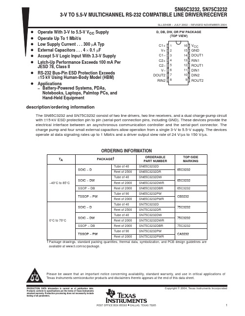
PACKAGING INFORMATIONOrderable Device Status(1)PackageType PackageDrawingPins PackageQtyEco Plan(2)Lead/Ball Finish MSL Peak Temp(3)SN65C3232D ACTIVE SOIC D1640Green(RoHS&no Sb/Br)CU NIPDAU Level-1-260C-UNLIMSN65C3232DBR ACTIVE SSOP DB162000Green(RoHS&no Sb/Br)CU NIPDAU Level-1-260C-UNLIMSN65C3232DBRE4ACTIVE SSOP DB162000Green(RoHS&no Sb/Br)CU NIPDAU Level-1-260C-UNLIMSN65C3232DBRG4ACTIVE SSOP DB162000Green(RoHS&no Sb/Br)CU NIPDAU Level-1-260C-UNLIMSN65C3232DE4ACTIVE SOIC D1640Green(RoHS&no Sb/Br)CU NIPDAU Level-1-260C-UNLIMSN65C3232DG4ACTIVE SOIC D1640Green(RoHS&no Sb/Br)CU NIPDAU Level-1-260C-UNLIMSN65C3232DR ACTIVE SOIC D162500Green(RoHS&no Sb/Br)CU NIPDAU Level-1-260C-UNLIMSN65C3232DRE4ACTIVE SOIC D162500Green(RoHS&no Sb/Br)CU NIPDAU Level-1-260C-UNLIMSN65C3232DRG4ACTIVE SOIC D162500Green(RoHS&no Sb/Br)CU NIPDAU Level-1-260C-UNLIMSN65C3232DW ACTIVE SOIC DW1640Green(RoHS&no Sb/Br)CU NIPDAU Level-1-260C-UNLIMSN65C3232DWE4ACTIVE SOIC DW1640Green(RoHS&no Sb/Br)CU NIPDAU Level-1-260C-UNLIMSN65C3232DWG4ACTIVE SOIC DW1640Green(RoHS&no Sb/Br)CU NIPDAU Level-1-260C-UNLIMSN65C3232DWR ACTIVE SOIC DW162000Green(RoHS&no Sb/Br)CU NIPDAU Level-1-260C-UNLIMSN65C3232DWRE4ACTIVE SOIC DW162000Green(RoHS&no Sb/Br)CU NIPDAU Level-1-260C-UNLIMSN65C3232DWRG4ACTIVE SOIC DW162000Green(RoHS&no Sb/Br)CU NIPDAU Level-1-260C-UNLIMSN65C3232PW ACTIVE TSSOP PW1690Green(RoHS&no Sb/Br)CU NIPDAU Level-1-260C-UNLIMSN65C3232PWE4ACTIVE TSSOP PW1690Green(RoHS&no Sb/Br)CU NIPDAU Level-1-260C-UNLIMSN65C3232PWG4ACTIVE TSSOP PW1690Green(RoHS&no Sb/Br)CU NIPDAU Level-1-260C-UNLIMSN65C3232PWR ACTIVE TSSOP PW162000Green(RoHS&no Sb/Br)CU NIPDAU Level-1-260C-UNLIMSN65C3232PWRE4ACTIVE TSSOP PW162000Green(RoHS&no Sb/Br)CU NIPDAU Level-1-260C-UNLIMSN65C3232PWRG4ACTIVE TSSOP PW162000Green(RoHS&no Sb/Br)CU NIPDAU Level-1-260C-UNLIMSN75C3232D ACTIVE SOIC D1640Green(RoHS&no Sb/Br)CU NIPDAU Level-1-260C-UNLIMSN75C3232DBR ACTIVE SSOP DB162000Green(RoHS&no Sb/Br)CU NIPDAU Level-1-260C-UNLIMSN75C3232DBRE4ACTIVE SSOP DB162000Green(RoHS&no Sb/Br)CU NIPDAU Level-1-260C-UNLIMSN75C3232DBRG4ACTIVE SSOP DB162000Green(RoHS&no Sb/Br)CU NIPDAU Level-1-260C-UNLIMOrderable Device Status(1)PackageType PackageDrawingPins PackageQtyEco Plan(2)Lead/Ball Finish MSL Peak Temp(3)SN75C3232DE4ACTIVE SOIC D1640Green(RoHS&no Sb/Br)CU NIPDAU Level-1-260C-UNLIMSN75C3232DG4ACTIVE SOIC D1640Green(RoHS&no Sb/Br)CU NIPDAU Level-1-260C-UNLIMSN75C3232DR ACTIVE SOIC D162500Green(RoHS&no Sb/Br)CU NIPDAU Level-1-260C-UNLIMSN75C3232DRE4ACTIVE SOIC D162500Green(RoHS&no Sb/Br)CU NIPDAU Level-1-260C-UNLIMSN75C3232DRG4ACTIVE SOIC D162500Green(RoHS&no Sb/Br)CU NIPDAU Level-1-260C-UNLIMSN75C3232DW ACTIVE SOIC DW1640Green(RoHS&no Sb/Br)CU NIPDAU Level-1-260C-UNLIMSN75C3232DWE4ACTIVE SOIC DW1640Green(RoHS&no Sb/Br)CU NIPDAU Level-1-260C-UNLIMSN75C3232DWG4ACTIVE SOIC DW1640Green(RoHS&no Sb/Br)CU NIPDAU Level-1-260C-UNLIMSN75C3232DWR ACTIVE SOIC DW162000Green(RoHS&no Sb/Br)CU NIPDAU Level-1-260C-UNLIMSN75C3232DWRE4ACTIVE SOIC DW162000Green(RoHS&no Sb/Br)CU NIPDAU Level-1-260C-UNLIMSN75C3232DWRG4ACTIVE SOIC DW162000Green(RoHS&no Sb/Br)CU NIPDAU Level-1-260C-UNLIMSN75C3232PW ACTIVE TSSOP PW1690Green(RoHS&no Sb/Br)CU NIPDAU Level-1-260C-UNLIMSN75C3232PWE4ACTIVE TSSOP PW1690Green(RoHS&no Sb/Br)CU NIPDAU Level-1-260C-UNLIMSN75C3232PWG4ACTIVE TSSOP PW1690Green(RoHS&no Sb/Br)CU NIPDAU Level-1-260C-UNLIMSN75C3232PWR ACTIVE TSSOP PW162000Green(RoHS&no Sb/Br)CU NIPDAU Level-1-260C-UNLIMSN75C3232PWRE4ACTIVE TSSOP PW162000Green(RoHS&no Sb/Br)CU NIPDAU Level-1-260C-UNLIMSN75C3232PWRG4ACTIVE TSSOP PW162000Green(RoHS&no Sb/Br)CU NIPDAU Level-1-260C-UNLIM(1)The marketing status values are defined as follows:ACTIVE:Product device recommended for new designs.LIFEBUY:TI has announced that the device will be discontinued,and a lifetime-buy period is in effect.NRND:Not recommended for new designs.Device is in production to support existing customers,but TI does not recommend using this part in a new design.PREVIEW:Device has been announced but is not in production.Samples may or may not be available.OBSOLETE:TI has discontinued the production of the device.(2)Eco Plan-The planned eco-friendly classification:Pb-Free(RoHS),Pb-Free(RoHS Exempt),or Green(RoHS&no Sb/Br)-please check /productcontent for the latest availability information and additional product content details.TBD:The Pb-Free/Green conversion plan has not been defined.Pb-Free(RoHS):TI's terms"Lead-Free"or"Pb-Free"mean semiconductor products that are compatible with the current RoHS requirements for all6substances,including the requirement that lead not exceed0.1%by weight in homogeneous materials.Where designed to be soldered at high temperatures,TI Pb-Free products are suitable for use in specified lead-free processes.Pb-Free(RoHS Exempt):This component has a RoHS exemption for either1)lead-based flip-chip solder bumps used between the die and package,or2)lead-based die adhesive used between the die and leadframe.The component is otherwise considered Pb-Free(RoHS compatible)as defined above.Green(RoHS&no Sb/Br):TI defines"Green"to mean Pb-Free(RoHS compatible),and free of Bromine(Br)and Antimony(Sb)based flame retardants(Br or Sb do not exceed0.1%by weight in homogeneous material)(3)MSL,Peak Temp.--The Moisture Sensitivity Level rating according to the JEDEC industry standard classifications,and peak solder temperature.Important Information and Disclaimer:The information provided on this page represents TI's knowledge and belief as of the date that it is provided.TI bases its knowledge and belief on information provided by third parties,and makes no representation or warranty as to the accuracy of such information.Efforts are underway to better integrate information from third parties.TI has taken and continues to take reasonable steps to provide representative and accurate information but may not have conducted destructive testing or chemical analysis on incoming materials and chemicals.TI and TI suppliers consider certain information to be proprietary,and thus CAS numbers and other limited information may not be available for release.In no event shall TI's liability arising out of such information exceed the total purchase price of the TI part(s)at issue in this document sold by TI to Customer on an annual basis.TAPE AND REEL INFORMATION*All dimensions are nominal Device Package Type Package DrawingPinsSPQ Reel Diameter (mm)Reel Width W1(mm)A0(mm)B0(mm)K0(mm)P1(mm)W (mm)Pin1Quadrant SN65C3232DBR SSOPDB 162000330.016.48.2 6.6 2.512.016.0Q1SN65C3232DR SOICD 162500330.016.4 6.510.3 2.18.016.0Q1SN65C3232DWR SOICDW 162000330.016.410.7510.7 2.712.016.0Q1SN65C3232PWR TSSOPPW 162000330.012.47.0 5.6 1.68.012.0Q1SN75C3232DBR SSOPDB 162000330.016.48.2 6.6 2.512.016.0Q1SN75C3232DR SOICD 162500330.016.4 6.510.3 2.18.016.0Q1SN75C3232DWR SOICDW 162000330.016.410.7510.7 2.712.016.0Q1SN75C3232PWR TSSOP PW 162000330.012.47.0 5.6 1.68.012.0Q1*All dimensions are nominalDevice Package Type Package Drawing Pins SPQ Length(mm)Width(mm)Height(mm) SN65C3232DBR SSOP DB162000346.0346.033.0 SN65C3232DR SOIC D162500333.2345.928.6 SN65C3232DWR SOIC DW162000346.0346.033.0 SN65C3232PWR TSSOP PW162000346.0346.029.0 SN75C3232DBR SSOP DB162000346.0346.033.0 SN75C3232DR SOIC D162500333.2345.928.6 SN75C3232DWR SOIC DW162000346.0346.033.0 SN75C3232PWR TSSOP PW162000346.0346.029.0IMPORTANT NOTICETexas Instruments Incorporated and its subsidiaries(TI)reserve the right to make corrections,modifications,enhancements,improvements, and other changes to its products and services at any time and to discontinue any product or service without notice.Customers should obtain the latest relevant information before placing orders and should verify that such information is current and complete.All products are sold subject to TI’s terms and conditions of sale supplied at the time of order acknowledgment.TI warrants performance of its hardware products to the specifications applicable at the time of sale in accordance with TI’s standard warranty.Testing and other quality control techniques are used to the extent TI deems necessary to support this warranty.Except where mandated by government requirements,testing of all parameters of each product is not necessarily performed.TI assumes no liability for applications assistance or customer product design.Customers are responsible for their products and applications using TI components.To minimize the risks associated with customer products and applications,customers should provide adequate design and operating safeguards.TI does not warrant or represent that any license,either express or implied,is granted under any TI patent right,copyright,mask work right, or other TI intellectual property right relating to any combination,machine,or process in which TI products or services are rmation published by TI regarding third-party products or services does not constitute a license from TI to use such products or services or a warranty or endorsement e of such information may require a license from a third party under the patents or other intellectual property of the third party,or a license from TI under the patents or other intellectual property of TI.Reproduction of TI information in TI data books or data sheets is permissible only if reproduction is without alteration and is accompanied by all associated warranties,conditions,limitations,and notices.Reproduction of this information with alteration is an unfair and deceptive business practice.TI is not responsible or liable for such altered rmation of third parties may be subject to additional restrictions.Resale of TI products or services with statements different from or beyond the parameters stated by TI for that product or service voids all express and any implied warranties for the associated TI product or service and is an unfair and deceptive business practice.TI is not responsible or liable for any such statements.TI products are not authorized for use in safety-critical applications(such as life support)where a failure of the TI product would reasonably be expected to cause severe personal injury or death,unless officers of the parties have executed an agreement specifically governing such use.Buyers represent that they have all necessary expertise in the safety and regulatory ramifications of their applications,and acknowledge and agree that they are solely responsible for all legal,regulatory and safety-related requirements concerning their products and any use of TI products in such safety-critical applications,notwithstanding any applications-related information or support that may be provided by TI.Further,Buyers must fully indemnify TI and its representatives against any damages arising out of the use of TI products in such safety-critical applications.TI products are neither designed nor intended for use in military/aerospace applications or environments unless the TI products are specifically designated by TI as military-grade or"enhanced plastic."Only products designated by TI as military-grade meet military specifications.Buyers acknowledge and agree that any such use of TI products which TI has not designated as military-grade is solely at the Buyer's risk,and that they are solely responsible for compliance with all legal and regulatory requirements in connection with such use. TI products are neither designed nor intended for use in automotive applications or environments unless the specific TI products are designated by TI as compliant with ISO/TS16949requirements.Buyers acknowledge and agree that,if they use any non-designated products in automotive applications,TI will not be responsible for any failure to meet such requirements.Following are URLs where you can obtain information on other Texas Instruments products and application solutions:Products ApplicationsAmplifiers AudioData Converters AutomotiveDSP BroadbandClocks and Timers Digital ControlInterface MedicalLogic MilitaryPower Mgmt Optical NetworkingMicrocontrollers SecurityRFID TelephonyRF/IF and ZigBee®Solutions Video&ImagingWirelessMailing Address:Texas Instruments,Post Office Box655303,Dallas,Texas75265Copyright©2008,Texas Instruments Incorporated。
AC DC 10W 双输出电源模块说明书

AC/DC ConverterE22473610 Watt 2“ x 1“Single andDual OutputFeaturesRegulated Converter• Wide input range 85-305Vac• Operating temperature range: -40°C to +80°C • High effi ciency over entire load range • No external components necessary • Household certifi cation IEC/EN60335• Overvoltage category OVCIII (IEC62477-1)• 140% Peak load capabilityDescriptionThe RAC10-K/277 series are highly effi cient PCB-Mount power conversion modules with ultra-low energy losses even in light load conditions. Built for worldwide usage, the AC/DC units cover an enhanced mains input range of 85VAC up to 305VAC and come with international safety certifi cations for both industrial and household standards. These AC/DC modules offer fully protected single or dual outputs as well as EMC Class B compliance without the need of any external components. The 140% peak power capability makes the RAC10-K/277 series suitable for inductive, high start-up current or nonlinear loads. With a full load temperature range of -40°C to +65°C, they are ideal for always-on and standby mode operations in process automation, IoT and smart building applications.RAC10-K/277UL62368-1 certifi edCSA C22.2 No. 62368-1-14 certifi ed IEC/EN60950-1 certifi ed IEC/EN60335-1 certifi ed IEC/EN62368-1 certifi ed EN62233 certifi ed EN62477-1 certifi ed EN61204-3 compliantCB-ReportSelection GuidePart Input Output Output Effi ciency Max. Capacitive Number Voltage Range Voltage Current typ. (1) Load [VAC] [VDC] [mA] [%] [µF]RAC10-3.3SK/277 85-305 3.3 2500 79 10000RAC10-05SK/277 85-305 5 2000 82 8000RAC10-12SK/277 85-305 12 840 84 1500RAC10-15SK/277 85-305 15 670 85 1000RAC10-24SK/277 85-305 24 420 84 330RAC10-12DK/277 85-305 ±12 ±420 82 ±1200RAC10-15DK/277 85-305 ±15 ±340 83 ±1000Notes:Note1: Effi ciency is tested at 25°C with constant resistant mode at full load and 230VACModel NumberingS ingle or D ual OutputOutput VoltageRAC10-__ _K/277Ordering Examples:RAC10-05SK/277 10 Watt 5Vout Single Output RAC10-24SK/277 10 Watt 24Vout Single Output RAC10-12DK/277 10 Watt 12Vout Dual OutputSpecifi cations (measured @ Ta= 25°C, nominal input voltage (115/230VAC), full load and after warm-up)Specifi cations (measured @ Ta= 25°C, nominal input voltage (115/230VAC), full load and after warm-up)REGULATIONSParameter Condition Value Output Accuracy±1.0% typ. Line Regulation low line to high line±0.5% typ.Load Regulation0-100% load 3.3, 5Voutothers1.5% typ.1.0% typ.Cross Regulation dual output only±10.0% typ.Transient Response 25% load step changerecovery time4.0% max.500µsSpecifi cations (measured @ Ta= 25°C, nominal input voltage (115/230VAC), full load and after warm-up)PROTECTIONSParameter Type Value Input Fuse (4)T2A, slow blow Short Circuit Protection (SCP)Hiccup, automatic restart Over Voltage Protection (OVP)150% - 195%, latch off mode Over Load Protection (OLP)150% - 195%, hiccup mode Over Voltage Category (OVC)according to IEC/EN61477-1OVC III Class of Equipment Class II Isolation Voltage tested for 1 minute4kVACIsolation ResistanceI/P to O/P Isolation Voltage 500VDC1GΩ min.Isolation Capacitance100kHz/0.1V100pF max. Insulation Grade reinforced Leakage Current0.25mA max.Notes:Specifi cations (measured @ Ta= 25°C, nominal input voltage (115/230VAC), full load and after warm-up)SAFETY AND CERTIFICATIONSCertifi cate Type (Safety)Report / File Number StandardAudio/Video, information and communication technology equipment - Safety requirements E224736UL62368-1, 2nd Edition, 2014CAN/CSA C22.2 No. 62368-1-14, 2nd Edition, 2014Information Technology Equipment, General Requirements for Safety (CB Scheme)E491408-A4-CB-1IEC60950-1:2005, 2nd Edition + A2:2013Information Technology Equipment, General Requirements for Safety (LVD)EN60950-1:2006 + A2:2013Household and similar electrical appliances - Safety - Part 1: General requirements LCS170821028CSIEC60335-1:2010 + A2:2016 + C1:2016, 5th EditionEN60335-1:2012 + A11:2014Audio/Video, information and communication technology equipment - Safetyrequirements (CB Scheme)16BCS10045 11IEC62368-1:2014, 2nd EditionAudio/Video, information and communication technology equipment - Safetyrequirements (LVD)EN62368-1:2014 + A11:2017 Measurement methods for electromagnetic fi elds of household appliancesand similar apparatus with regard to human exposureLCS170821028CS EN62233:2008Safety requirements for power electronic converter systems and equipment - Part 1: General LCS181212006CSIEC62477-1:2012 + A1:2016, 1st EditionEN62477-1: 2012 + A1:2017Specifi cations (measured @ Ta= 25°C, nominal input voltage (115/230VAC), full load and after warm-up)DIMENSION and PHYSICAL CHARACTERISTICSParameterTypeValueMaterial case potting PCB baseplateblack plastic (UL94V-0)silicone (UL94V-0)FR4 (UL94V-0)plastic (UL94V-0)Dimension (LxWxH)52.5 x 27.4 x 23.0mmWeight65g typ.Certifi cate Type (Safety)Report / File NumberStandard EAC Safety of Low Voltage Equipment RU-AT.03.67361TP TC 004/020, 2011RoHS2+RoHS 2011/65/EU + AM2015/863EMC ComplianceConditionsStandard / CriterionLow-voltage power supplies DC output - Part 3: Electromagnetic compatibility LCS170821088AE EN61204-3:2000, Class BInformation technology equipment - Radio disturbance characteristics - Limits and methods of measurement AS/NZS CSPR 22:2009 + A1:2010, Class BESD Electrostatic discharge immunity test±8kV Air; ±4kV Contact EN61000-4-2: 2009, Criteria BRadiated, radio-frequency, electromagnetic fi eld immunity test 10V/m, 80MHz-1GHz 3V/m, 1.5GHz-2GHz 1V/m, 2GHz-2.7GHz EN61000-4-3: 2006 + A2, 2010, Criteria AFast Transient and Burst Immunity AC In Port: ±2.0kV DC Out Port: ±2.0kV EN61000-4-4:2012, Criteria B Surge ImmunityAC In Port: ±1.0kV L-PE, N-PE ±2.0kV DC Out Port: ±0.5kVEN61000-4-5:2014, Criteri B Immunity to conducted disturbances, induced by radio-frequency fi elds 10VrmsEN61000-4-6:2014, Criteria A Power Magnetic Field Immunity 50Hz, 1A/m EN61000-4-8:2010, Criteria A Voltage Dips and InterruptionsVoltages Dips: >95%Voltage Dips: 30%Interruptions: >95%EN61000-4-11: 2004, Criteria B EN61000-4-11: 2004, Criteria C EN61000-4-11: 2004, Criteria CVoltage Fluctuations and Flicker in Public Low-Voltage Systems <=16A per phaseEN61000-3-3: 2013Notes:Note6: If output is connected to GND, please contact RECOM tech support for adviceSpecifi cations (measured @ Ta= 25°C, nominal input voltage (115/230VAC), full load and after warm-up) ArrayPACKAGING INFORMATIONParameter Type Value Packaging Dimension (LxWxH)tube490.0 x 56.0 x 40.0mm Packaging Quantity15pcs Storage Temperature Range-40°C to +85°C Storage Humidtiy non-condensing20% to 90% RHThe product information and specifications may be subject to changes even without prior written notice.The product has been designed for various applications; its suitability lies in the responsibility of each customer. Theproducts are not authorized for use in safety-critical applications without RECOM’s explicit written consent. A safety-critical application is an application where a failure may reasonably be expected to endanger or cause。
Assignment HBCL 4103

FAKULTI PENDIDIKAN DAN BAHASASEMESTER MEI / 2014 ( SMP KHAS)HBCL 4103KESUSASTERAAN BAHASA CINA IINAMA TUTOR : PN. LO CHIN CHINNAMA : KOH FANG NGEENO. MATRIKULASI : 840915125330001NO. KAD PENGNEALAN: 840915-12-5330NO. TELEFON : 0128149650E-MEL : fangee@.myPUSAT PEMBELAJARAN : PUSAT PEMBELAJARAN TAWAU目录序号题目页数1.0 前言 22.0 苏轼词作成就综述 3 - 53.0 苏轼与柳永对词坛变革的贡献3.1 例子分析 6 - 133.2 总结分析14 - 164.0 结言175.0 参考资料186.0 附件19 1.0 前言苏轼是中国北宋文学家、书画家。
字子瞻,号东坡居士。
宋代眉州(今四川省眉山市)人。
父苏洵、弟苏辙都是著名古文学家,世称“三苏”。
嘉佑进士,任凤翔府签判,主张改革弊政。
神宗时反对变法,但在密州、徐州任上抗洪灭蝗,赈贫救孤、颇多政绩。
苏轼的词大都抒写仕途坎坷的感慨,也有反映民生疾苦、揭露现实黑暗之作。
苏轼是宋代文化孕育出来的旷世奇才,历经磨难而笑对人生,思想自由、品格坚贞、坦荡旷达,其文如行云流水,行于所当行,止于不可不止;其诗如天地奇观,于境无所不收,于情无所不畅;其词如天风海雨逼人,指出向上一路。
无论从哪个方面衡量,他都是宋文学发展到尖峰时期的伟大的代表作家。
苏轼词作历来颇受尊崇。
苏轼对词的贡献很突出。
苏轼出现前,词的内容受传统念束缚,局限于旖旎温柔的艳情腻语的范围之内;苏轼则吊古伤今、述电咏怀、感叹时政,描绘山川景色、农村风光,以至谈论哲理等题材都进入了词中,大大开拓了词的题材与意境,为宋词的民展打开了新的局面。
Assignment2021(1)
ELEC6236Digital System Design Assignment2020/21Prof Mark ZwolinskiNovember20,20201ObjectiveThe objective of this assignment is to design an adder for two32-bitfloating point numbers. Y our design should be written in SystemVerilog and must simulate and synthesise correctly. Y our code will be assessed automatically–by compiling your SystemVerilog code and running it through the design tools.Half of the marks for this assignment(10)will be awarded for passing tests.Y ou must also complete a short report,describing what you have done.The other half of the marks(10)will be for this report.This assignment is designed to test your ability to write correct SystemVerilog code and to use the design tools.The assignment is worth20%of the module marks and should therefore take you about30hours to complete.Y ou may discuss the assignment with other students,but the code that you submit for as-sessment must be your own work.Please ensure you are familiar with the rules on academic integrity and the penalties for violating those rules.2Specification2.1Floating-point formatIEEE Standard754defines the format offloating point numbers.For this assignment,numbers should be represented in the32-bit form(also known as binary32):Bit31–Sign bit,0for positive numbers,1for negative numbers.Bits30-23(8bits)–Signed exponent.This is a power of2,biased by127.For example,the pattern011111002is12410.This represents the value124-127=-3,so the mantissa(see below) is multiplied by2−3.Bits22-0(23bits)–Mantissa.This is the fractional part of the number.There is an assumed leading1,which is not stored.Example(from Wikipedia):0.1562510is represented in binary as0.001012(that is,1/8+ 1/32).This can be written as1.012×2−3.As we have seen,the exponent,−3is stored as 127−3=12410=011111002.The mantissa is stored as010000000000000000000002–the leading1is not stored,it is assumed.The sign bit is0.2.2AdderY ou are asked to design an adder that takes two normalized32-bitfloating point numbers and adds them to give a normalized result.Y our adder should handle the‘special’numbers:zero, positive and negative infinity and‘Not a Number(NaN)’.Y ou do not have to consider other special cases.Y ou may use either‘round to zero’(truncation)or‘round to nearest’.Although it is possible,in principle,to design this as a combinational circuit,you must design a sequentialcircuit.There is no upper limit to the number of cycles that may be taken,so long as the design meets the timing requirements given in the next section.Hints:To add twofloating point numbers,it is necessary to adjust one number so that the exponents of the two numbers are the same.So,to do this,thefields of eachfloating point number(sign,mantissa,exponent)need to be extracted,the implicit leading1of each mantissa needs to be restored.If the mantissa of a number is shifted left or right,the exponent for that number is decremented or incremented by one,respectively.This form of afloating point number is known as a denormalized number.One of the mantissas(which one?)needs to be shifted(which way?)until the exponents of the twofloating point numbers are the same. The mantissas are then added or subtracted,according to the sign bits.The resulting number then has to be normalized.Although denormalized numbers are allowed under some circumstances,in this case returning a denormalized number would be wrong(why?).2.3TimingY our design must be synchronous.The system must be sensitive to the positive edge of the clock(only).Y ou should include an active low asynchronous reset that will set the contents of all registers to0.Y our adder must have a‘ready’output.This should be asserted for one clock cycle only.The adder has one32-bit input bus and one32-bit output bus.When the‘ready’signal is asserted, the adder expects thefirst input on the next clock cycle and the second input on the one after that.The sum is available in the same clock cycle as the‘ready’signal.In other words,a new calculation can begin as soon as the previous calculation is complete.3AssessmentY our design will be simulated with a testbench that will use some test cases.First,the reset will be tested.Then some‘corner cases’will be tried.For example:•0.0+0.0=0.0•0.0+1.0=1.0•−1.0+1.0=0.0The adder will then be tested with some arbitrary numbers.Y our design will be scored for each test that is passed.The sum output must be correctly normalized–you will get no marks for a result that does not conform to the IEEE standard.The design will then be validated with Verilator and Quartus.Marks will be deducted for warnings or errors that would cause the design to be synthesised incorrectly.4SubmissionY ou must submit twofiles.Thefirstfile,fpadder.sv,contains your code.This may contain more than one module;the header of the main module must be as follows:module fpadder(output logic[31:0]sum,output logic ready,input logic[31:0]a,input logic clock,nreset);Y ou must also submit a brief report of2pages,Design Report.pdf.Y ou can create this PDF file using either the Word or Latex templates provided.Please check that the PDFfile opens correctly in Acrobat.Y ou may submit multiple versions of your SystemVerilog code and thefinal report.Only the last version will be assessed.The code in thefinal submission will be automatically marked. The code in yourfirst5submissions only will also be automatically marked and the score for these submissions will be emailed back to you,but the scores will not be part of thefinal assessment.The deadline for submission is16:00on T te submissions will be penalised in line with ECS regulations.Please ensure that your reportfile is included with your final submission.Appendix:Behavioural ModelThe following code is a functionally-equivalent,behavioural model of the adder.Y ou can use this to verify your design,by comparing the bit pattens.This model completes in one clock cycle–your design is likely to require more cycles–but meets the timing specification.Note.Y ou must not use the real or shortreal types in your design.All submitted de-signs will be checked for these types before simulation and if the test fails,will not be simulated or synthesised.In other words you will receive zero marks.module fpadder_behav(output logic[31:0]sum,output logic ready,input logic[31:0]a,input logic clock,nreset); //to allow inputs to be loaded in successionenum{start,loada,loadb}state;shortreal rsum,ra;//shortreal is32bit floating pointalways@(*)sum=$shortrealtobits(rsum);//converts real to bitsalways@(*)ra=$bitstoshortreal(a);//converts bits to realalways@(posedge clock,negedge nreset)if(˜nreset)beginrsum<=0;state<=start;endelsebegin//This is a state machine,but there are other ways to do this case(state)start:beginstate<=loada;endloada:beginrsum<=ra;state<=loadb;endloadb:beginrsum<=rsum+ra;state<=start;endendcaseendalways@(*)ready=(state==start);endmoduleAn outline testbench can be used to simulate this design–and yours. module test_fpadder;logic[31:0]sum;logic ready;logic[31:0]a;logic clock,nreset;shortreal reala,realsum;fpadder_behav a1(.*);initialbeginnreset=’1;clock=’0;#5ns nreset=’1;#5ns nreset=’0;#5ns nreset=’1;forever#5ns clock=˜clock;endinitialbegin@(posedge clock);//wait for clock to start@(posedge ready);//wait for ready@(posedge clock);//wait for next clock tickreala= 1.0;a=$shortrealtobits(reala);@(posedge clock);reala=-2.0;a=$shortrealtobits(reala);@(posedge ready);realsum=$bitstoshortreal(sum);$display("%f\n",realsum);endendmodule。
BenQ 项目仪产品说明书
Table of ContentsImportant safety instructions (4)Notice (5)Laser notice (5)Cooling notice (5)Product information (6)Shipping contents (6)Specifications (6)Control terminals (6)Remote control (7)Installation (8)Projection dimensions (8)Adjusting the projector position (10)LED Indicators (11)Dimensions (12)Projector dimensions (12)Ceiling mount installation diagram (12)RS232 command (13)RS232 pin assignment (13)Regulatory Statements (115)Please visit below website for latest version of User Manual / Installation Guide./3Important safety instructionsY our projector is designed and tested to meet the latest standards for safety of information technology equipment. However, to ensure safe use of this product, it is important that you follow the instructions mentioned in the user manual / installation guide and marked on the product.1.Please read the user manual / installation guide before you operate your projector. Save it for futurereference.2.Do not look straight at the projector lens during operation. The intense light beam may damage your eyes.3.Refer servicing to qualified service personnel.4.Always open the lens shutter (if any) or remove the lens cap (if any) when the projector light source ison.5. The light source becomes extremely hot during operation.6. In some countries, the line voltage is NOT stable. This projector is designed to operate safely within a mains voltagebetween 100 to 240 volts AC, but could fail if power cuts or surges of ±10 volts occur. In areas where the mains voltage may fluctuate or cut out, it is recommended that you connect your projector through a power stabilizer, surge protector or uninterruptible power supply (UPS).7. Do not block the projection lens with any objects when the projector is under operation as this could cause theobjects to become heated and deformed or even cause a fire. T o temporarily turn off the light source, use the blank function.8. Do not operate light sources beyond the rated light source life.9. Do not place this product on an unstable cart, stand, or table. The product may fall, sustaining serious damage.10. Do not attempt to disassemble this projector. There are dangerous high voltages inside which may cause death if youshould come into contact with live parts.Under no circumstances should you ever undo or remove any other covers. Refer servicing only to suitably qualified professional service personnel.11. Do not block the ventilation holes.- Do not place this projector on a blanket, bedding or any other soft surface.- Do not cover this projector with a cloth or any other item.- Do not place inflammables near the projector.If the ventilation holes are seriously obstructed, overheating inside the projector may result in a fire.12. Do not stand the projector on end vertically. Doing so may cause the projector to fall over, causing injury or resultingin damage to the projector.13. Do not step on the projector or place any objects upon it. Besides probable physical damage to the projector, doing somay result in accidents and possible injury.14. When the projector is under operation, you may sense some heated air and odor from its ventilation grill. It is anormal phenomenon and not a product defect.15. Do not place liquids near or on the projector. Liquids spilled into the projector may cause it to fail. If the projectordoes become wet, disconnect it from the power supply's power outlet and call BenQ to have the projector serviced.16. This apparatus must be earthed.17. Do not place this projector in any of the following environments.- Space that is poorly ventilated or confined. Allow at least 50 cm clearance from walls and free flow of air around the projector.- Locations where temperatures may become excessively high, such as the inside of a car with all windows rolled up.- Locations where excessive humidity, dust, or cigarette smoke may contaminate optical components, shorten the projector's life span and darken the image.- Locations near fire alarms- Locations with an ambient temperature above 40°C / 104°F- Locations where the altitudes are higher than 3000 m (10000 feet).45NoticeLaser noticeThis symbol indicates that there is a potential hazard of eye exposure to laser radiation unless the instructions are closely followed.CLASS 1 LASER PRODUCTCooling noticeThis Laser Product is designated as Class 1 during all procedures of SER LIGHT - AVOID DIRECT EYE EXPOSURE.Do not point laser or allow laser light to be directed or reflected toward other people or reflective objects.Direct or scattered light can be hazardous to eyes and skin.There is a potential hazard of eye exposure to laser radiation if the included instructions are not followed.Caution – use of controls or adjustments or performance of procedures other than those specified herein may result in hazardous radiation exposure.VentilationCaution for installationFor proper ventilation of the projector, make sure to leave some space around the projector as shown in the illustration below:• T able • T able• Ceiling• Stacking• Avoid using the projector in a poorly ventilated or confined space.• The light source life may be affected if the projector is used tilted at an angle of more than + 15 degrees.50 cm 50 cm6Product informationShipping contentsSpecificationsControl terminalsProjector Remote control and batteries Installation guide Power cordLK952LK953STDisplay system 1-CHIP DMDResolution 1920 (H) x 1080 (V)4K UHD 3840X2160 on screen Light source Laser diode Throw ratio1.36 ~2.180.81 ~ 0.89Power consumption 585 W (Max); < 0.5 W (Standby)Dimensions 490 mm (W) x 159 mm (H) x 380 mm (D)Weight10.1 Kg (22.27 lbs)• WIRED REMOTEFor connection to a wired remote control.• RS232Standard 9-pin D-sub interface for connection to PC control system and projector maintenance.• USB MINI-BFor firmware upgrade only.• USB TYPE ASupport 5V/2A output.• LANFor connection to RJ45 Cat5/Cat6 Ethernet cable to control the projector through a network.• HDBaseTFor connection to RJ45 Cat5/Cat6 cable to input uncompressed high-definition video (HD).• HDMI 1 (HDCP2.2)Connection to HDMI source.• HDMI 2Connection to HDMI source.• PC IN15-pin VGA port for connection to RGB source or PC.• MONITOR OUTConnection to other display equipment for concurrent playback display. (Used with PC IN port.)• AUDIO INConnection to an audio input source via an audio cable. (Used with PC IN port.)• AUDIO OUTConnection to a speaker or headset.• 12V TRIGGERT rigger external devices such as an electric screen or light control, etc.• HDMI 3Connection to HDMI source.7Remote control• HDMI OUTConnection to other display equipment for concurrent playback display. (Used with HDMI 3port.)* This button is not available for this model.8InstallationProjection dimensionsThe screen aspect ratio is 16:9 and the projected picture is in a 16:9 aspect ratioLK952Screen sizeDistance from screen (mm)Diagonal W (mm)H (mm)Min length AverageMax lengthInch mm(max. zoom)(min. zoom)307626643749031176144840101688649812041567193050127011076231505195924136015241328747180623512896802032 1771 996 2409 3135 3861 902286 1992 1121 2710 3527 4343 1002540 2214 1245 3011 3918 4826 1102794 2435 1370 3312 4310 5309 1203048 2657 1494 3613 4702 5791 130**** **** 1619 3914 5094 6274 1403556 30991743 4215 5486 6757 150**** **** 1868 4516 5878 7239 1604064 3542 1992 4817 6269 7722 1704318 3763 2117 5118 6661 8204 180**** **** 2241 5419 7053 8687 1904826 4206 2366 5720 7445 9170 2005080 4428 2491 6022 7837 9652 2506350 5535 3113 7527 9796 12065 30076206641373690321175514478H9LK953STScreen sizeDistance from screen (mm)Diagonal W (mm)H (mm)Min length AverageMax lengthInch mm(max. zoom)(min. zoom)3076266437453856559140101688649871775378850127011076238979419856015241328747107611291182802032 1771 996 1435 1505 1576 902286 1992 1121 1614 1694 1773 1002540 2214 1245 1793 1882 1970 1102794 2435 1370 1972 2070 2167 1203048 2657 1494 2152 2258 2364 130**** **** 1619 2331 2446 2561 1403556 3099 1743 2510 2634 2758 150**** **** 1868 2690 2823 2955 1604064 3542 1992 2869 3011 3152 1704318 3763 2117 3048 3199 3349 180**** **** 2241 3228 3387 3547 1904826 4206 2366 3407 3575 3744 2005080 4428 2491 3586 3763 3941 2506350 5535 3113 4483 4704 4926 300762066413736538056455911• T o optimize your projection quality, we suggest you do the projection within non-gray area.• All measurements are approximate and may vary from the actual sizes.BenQ recommends that if you intend to permanently install the projector, you should physically test the projection size and distance using the actual projector in situ before you permanently install it, so as to make allowance for this projector's optical characteristics. This will help you determine the exact mounting position so that it best suits your installation location.• Ceiling installation must be done by a qualified professional. Contact your dealer for more information. It is not recommended you install the projector yourself.• Only use the projector on a solid, level surface. Serious injury and damage can occur if the projector is dropped.• Do not use the projector in an environment where extreme temperature occurs. The projector must be used at temperatures between 32 degrees Fahrenheit (0 degrees Celsius) and 104 degrees Fahrenheit (40 degrees Celsius).• Screen damage will occur if the projector is exposed to moisture, dust or smoke.• Do not cover the vents on the projector. Proper ventilation is required to dissipate heat. Damage to the projector will occur if the vents are covered.10Adjusting the projector positionShifting the projection lensEffective projection positionLED Indicators11DimensionsProjector dimensions490 mm (W) x 159 mm (H) x 380 mm (D)Unit: mmCeiling mount installation diagram12RS232 commandRS232 pin assignmentNo.Serial No.Serial1NC6NC2RX7RTSZ3TX8CTSZ4NC9NC5GNDFunction T ype Operation ASCIIPower Write Power On<CR>*pow=on#<CR> Write Power off<CR>*pow=off#<CR> Read Power Status<CR>*pow=?#<CR>Source Selection Write COMPUTER<CR>*sour=RGB#<CR> Write HDMI<CR>*sour=hdmi#<CR> Write HDMI 2<CR>*sour=hdmi2#<CR> Write HDMI 3<CR>*sour=hdmi3#<CR> Write HDBaseT<CR>*sour=hdbaset#<CR> Read Current source<CR>*sour=?#<CR>Audio Control Write Mute On<CR>*mute=on#<CR> Write Mute Off<CR>*mute=off#<CR> Read Mute Status<CR>*mute=?#<CR> Write Volume +<CR>*vol=+#<CR> WriteVolume -<CR>*vol=-#<CR> Write Volume level for customer<CR>*vol=value#<CR> Read Volume Status<CR>*vol=?#<CR>Picture Mode Write Presentation<CR>*appmod=preset#<CR> Write sRGB<CR>*appmod=srgb#<CR> Write Bright<CR>*appmod=bright#<CR> Write DICOM<CR>*appmod=dicom#<CR> Write Vivid<CR>*appmod=vivid#<CR> Write User1<CR>*appmod=user1#<CR> Write User2<CR>*appmod=user2#<CR> Read Picture Mode<CR>*appmod=?#<CR>Picture Setting Write Contrast +<CR>*con=+#<CR> Write Contrast -<CR>*con=-#<CR> Read Contrast value<CR>*con=?#<CR> Write Brightness +<CR>*bri=+#<CR> Write Brightness -<CR>*bri=-#<CR> Read Brightness value<CR>*bri=?#<CR> Write Color +<CR>*color=+#<CR> Write Color -<CR>*color=-#<CR> Read Color value<CR>*color=?#<CR> Write Sharpness +<CR>*sharp=+#<CR> Write Sharpness -<CR>*sharp=-#<CR> Read Sharpness value<CR>*sharp=?#<CR> Write Color Temperature-Warm<CR>*ct=warm#<CR> Write Color Temperature-Normal<CR>*ct=normal#<CR> Write Color Temperature-Cool<CR>*ct=cool#<CR> Write Color Temperature-lamp native<CR>*ct=native#<CR> Read Color Temperature Status<CR>*ct=?#<CR>Write Aspect 4:3<CR>*asp=4:3#<CR> Write Aspect 16:9<CR>*asp=16:9#<CR> Write Aspect 16:10<CR>*asp=16:10#<CR> Write Aspect Auto<CR>*asp=AUTO#<CR> Write Aspect Real<CR>*asp=REAL#<CR> Read Aspect Status<CR>*asp=?#<CR> Write Auto<CR>*auto#<CR>Operation Settings Write Projector Position-Front Table<CR>*pp=FT#<CR>Write Projector Position-Rear Table<CR>*pp=RE#<CR>Write Projector Position-Rear Ceiling<CR>*pp=RC#<CR>Write Projector Position-Front Ceiling<CR>*pp=FC#<CR>Write Quick auto search<CR>*QAS=on#<CR>Write Quick auto search<CR>*QAS=off#<CR>Read Quick auto search status<CR>*QAS=?#<CR>Read Projector Position Status<CR>*pp=?#<CR>Write Direct Power On-on<CR>*directpower=on#<CR> Write Direct Power On-off<CR>*directpower=off#<CR> Read Direct Power On-Status<CR>*directpower=?#<CR> Write Standby Settings-Network on<CR>*standbynet=on#<CR> Write Standby Settings-Network off<CR>*standbynet=off#<CR> Read Standby Settings-Network Status<CR>*standbynet=?#<CR>Lamp Control Read Lamp hour<CR>*ltim=?#<CR>Write Normal mode<CR>*lampm=lnor#<CR>Write Eco mode<CR>*lampm=eco#<CR>Write Dimming mode<CR>*lampm=dimming#<CR> Write Custom mode<CR>*lampm=custom#<CR> Write Light level for custom mode <CR>*lampcustom=value#<CR> Read Light level status for custom mode<CR>*lampcustom=?#<CR> Read Lamp Mode Status<CR>*lampm=?#<CR>Function T ype Operation ASCIIMiscellaneous Read Model Name <CR>*modelname=?#<CR> Write Blank On<CR>*blank=on#<CR> Write Blank Off<CR>*blank=off#<CR> Read Blank Status<CR>*blank=?#<CR>Write Menu On<CR>*menu=on#<CR> Write Menu Off<CR>*menu=off#<CR> Write Up<CR>*up#<CR>Write Down<CR>*down#<CR>Write Right<CR>*right#<CR>Write Left<CR>*left#<CR>Write Enter / OK<CR>*enter#<CR>Write AMX Device Discovery-on<CR>*amxdd=on#<CR> Write AMX Device Discovery-off<CR>*amxdd=off#<CR> Read AMX Device Discovery Status<CR>*amxdd=?#<CR> Read Mac Address<CR>*macaddr=?#<CR> Write High Altitude mode on<CR>*Highaltitude=on#<CR> Write High Altitude mode off<CR>*Highaltitude=off#<CR> Read High Altitude mode status<CR>*Highaltitude=?#<CR>Function T ype Operation ASCII目錄重要安全說明 (18)注意 (19)雷射注意事項 (19)冷卻注意事項 (19)產品資訊 (20)包裝盒內容 (20)規格 (20)控制端子 (20)遙控器 (21)安裝 (22)投影尺寸 (22)調整投影機位置 (24)LED 指示燈 (25)尺寸 (26)投影機尺寸 (26)天花板安裝圖 (26)RS232 指令 (27)RS232 針腳分配 (27)Regulatory Statements (115)如需最新版使用手冊 / 安裝指南,請造訪下列網站。
CS221 Programming Assignment #2 1 CS 221, Autumn 1998 Programming Assignment #2 Digit Recog
1
Handout #30
CS 221, Autumn 1998 Programming Assignment #2: Digit Recognition
The nal submission for this programming assignment is due December 4. If you are using late days for this project, at most 5 late days can be taken, so the hard deadline for the project is the CS221 nal exam date. Note: You should work in teams of 2-3 for this project. Each team must send email to cs221-staff@cs with the team member's names and e-mail addresses by Thursday, November 19. If you fail to send us the e-mail by this date, we may deduct points from the
score of your nal program. You must send us the e-mail even if your team has not changed. Note that you are allowed to change your team even after you send us the e-mail.
2 Outline Of Tasks For You To Do
TLC2252A中文资料
POST OFFICE BOX 655303
• DALLAS, TEXAS 75265
1
元器件交易网 TLC225x, TLC225xA Advanced LinCMOS RAIL-TO-RAIL VERY R OPERATIONAL AMPLIFIERS
V n – Equivalent Input Noise Voltage – nV/ VN nv//Hz Hz
VDD = 5 V RS = 20 Ω T = 25°C 50 A
40
30
20
10 The TLC225x amplifiers, exhibiting high input impedance and low noise, are excellent for small-signal conditioning for high-impedance 0 sources, such as piezoelectric transducers. 101 10 2 10 3 10 4 Because of the micropower dissipation levels, f – Frequency – Hz these devices work well in hand-held monitoring Figure 1 and remote-sensing applications. In addition, the rail-to-rail output feature with single or split supplies makes this family a great choice when interfacing with analog-to-digital converters (ADCs). For precision applications, the TLC225xA family is available and has a maximum input offset voltage of 850 µV. This family is fully characterized at 5 V and ± 5 V.
Oslo B
Oslo Optiq® Technical User GroupOSLO, STOCKHOLM, LONDONMid-January 2020AGENDA1. Project Overview▪Migration Timeline▪Technical Specifications / Testing▪Differences between Millennium Exchange / SOLA and Optiq 2. Optiq® and Saturn Overview▪Connectivity▪Enablement▪Market Data▪Trade Reporting▪APA▪Record Keeping3. Clearing4. Next StepsPROJECT OVERVIEWCash Equities31 October 2020Derivatives26 September 2020Fixed Income31 October 202020192020Nov.Dec.Jan.Feb.Mar.Apr.MayJuneJul.Aug.Sep.Oct.Nov.Dec.Oslo Test Cash & derivativesTask Key milestone DR1 Der + Cash 1CCPs included in test environmentTest Fixed IncomeContingencyCash + FI Contingency DerivativesGO LIVE Derivatives GO LIVE Cash + FIDR2 Der +Cash + FI 2DR3Cash + FI3Connectivity test Oslo Test environmentavailable (EUA)Oslo Clients Membership contractual onboardingTechnical User Group #1Compliance workshopOslo Børs Market Data Licensing processMD fee andagreements availableSFTI Prod. Leased line for EUA and Prod readyOSLO BORS –MIGRATION TIMELINE –TENTATIVE PLANContingencyEuronext Optiq / Saturn EUATESTPRODPW•Please note that timeline may be subject to changeTECHNICAL DOCUMENTATION –PROJECT1.REGISTER AT CONNECT 2:▪https:///▪Register for Euronext Info Flash2.STAY UPDATED VIA DELTA ANNOUNCEMENTS▪https://www.oslobors.no/Oslo-Boers/Handel/Delta/Optiq3.SUPPORT▪****************************▪**************************OSLO BORS MIGRATION –MAIN AREAS OF CHANGESCurrent Area NextMillennium Exchange / SOLAOn ExchangeTrading(incl.Derivatives)OptiqTradeReporting(Off-Book OnExchange)Cash: SaturnAPASaturnLCH ltd, SIX,EuroCCPCCPCash: TBCMITCH,FixFAST,HSVFReal TimeMarket DataOptiq MDGOBRecRecordKeepingSaturnOslo BørsFTP ServerFiles basedMarket DataEuronext FTPServerTrading & Reporting Clearing Market Data Reg.Derivatives:OptiqDerivatives:LCH SA▪FNN▪SFTIStockholm POP fully available End Q1 / Early Q2 2020▪VFN? (Under discussion)▪SFTINETWORK CONNECTIVITYOslo ScandinaviaContinental EuropeO p t i qL C H S A▪FNN▪To be confirmed.▪SFTI▪To be confirmed▪VFN? (Under discussion)▪CMC from LCH▪Or via an ACP (Accredited Connectivity Parner)TEST POLICIESProviderMember in-house Member using providerMandatoryMandatoryMarket Makers: MandatoryFunctional Conformance1(Highly recommended for all)•Euronext assistance required (book timeslot on Connect). •Conformance policies as for Oslo Børs customers today.High Availability (HA)2ThrottlingFront to Back conformance with Clearing partner34Mandatory Mandatory Highly recommended•Test HA within allocated time slots provided by Euronext.Highly recommended Highly recommendedHighly recommended•Test throttling within allocated time slots provided by Euronext (buffered throttling only).Mandatory MandatoryN/A▪Reference data▪Files published early morning ▪Multicast based Market data▪ A and B stream as today▪Market Data recovery▪Multicast based▪No «Trade Only» gateway▪Start at secondary site fromwhere we left offKEY DIFFERENCES MILLENNIUM & SOLA / OPTIQReference Data / Conformance Market Data Disaster Recovery▪Trading at Last (TAL)▪Best Of Book (BoB)▪Liquidity Provider Programs▪Order Routing Solution▪Euronext Block▪Improved Market MakerProtection for ETNs▪Order types and TIFs▪StopLoss introduced▪GTT and PassiveOnly removed ▪SEP for Liquidity Providers only ▪Functionality very similar to that ofEquities▪New MIC Code: XOBD for derivatives▪Opening uncross at 09:01▪New solution for Market MakerProtection▪Changes to Market Maker spreadobligations▪New trading safeguards▪Discontinuation of Forwards▪Discontinuation of TM derivatives (EDGE)▪Discontinuance of MPS Trading Desk /Electronic trading access only▪TBDKEY FUNCTIONAL DIFFERENCES/ CHANGESEquities / ETNs / ETFs Derivatives Fixed IncomeTHE OPTIQ PLATFORM –A REMINDERTHE OPTIQ ARCHITECTUREThe Order Entry Gateway (OEG)OptiqOrder Entry GatewayMatching EngineMarket Data GatewaySBE (Binary)FIX 5.0 SP2BinaryEuronext The core components1The Matching Engine (ME)2The Market Data Gateway (MDG)3▪Two protocols available:▪FIX 5.0 SP2▪SBE (Simple Binary Encoding)Trading Members▪Market data provided via multicast feed in SBE formatSFTI® networkP e r s i s t e n c e E n g i n eIDS123Euronext Segmentation of Cash & Derivatives MarketsEquities Warrants and certificatesFixed Income EURONEXT CASH SEGMENTSETFsEuronext Block (MTF)Equity Derivatives Commodity DerivativesIndex Derivatives EURONEXT DERIVATIVES SEGMENTSNote that Dublin instruments are included in the Equities & ETFs segmentsPartitioning ▪An Optiq Partition is a technical subdivision of an Optiq SegmentMember benefits▪Resilience -Failures on one partition impact only a fraction of the market/clients ▪Scalability -Simple and seamless scalability model to guarantee stable latency OEG-2C MDG-2CME-2C Optiq Segment 1OEG-1A MDG-1A ME-1A OEG-2B MDG-2B ME-2B Optiq Segment 2OEG-2A MDG-2AME-2A▪On Optiq, Customers are provided Logical Access(es) to an Optiq Segment▪Logical Accesses provides access to all partitions of a Segment▪Customers must have at least oneLogical Access per market segment for which they have trading authorisations ▪Market Makers / Liquidity Providers may get dedicated Logical AccessesLogical AccessP a r t i t i o n 1Optiq Segment 2Optiq Segment 1P a r t i t i o n 1P a r t i t i o n 2P a r t i t i o n 3Logical AccessDrop Copy Logical AccessOrders and / or tradesDrop Copy service (via FIX 5.0 API) provides copies of trades and at Trading Member’srequest orders –Drop Copy Logical Accesses can be cross segmentsOptiq has the flexibility to load-balance instruments or contracts (for Derivatives markets) across the different partitions of a segment or add a partition to a segment . Customers must therefore refer to thestanding data files on a daily basis to get the PartitionID of the partition the instrument / contract is listed on.Optiq SegmentLogical Access 1PartitionAOE SESSION 1AOEG-1A MDG-1AME-1A OE SESSION 1BPartitionBOEG-1B MDG-1BME-1B Optiq SegmentPartitionAOE SESSION 1AOEG-1A MDG-1AME-1A PartitionBOEG-1B MDG-1BME-1B Logical Access 1Customers establish a physical connection to each partition of a segment i.e. no cross partitioningCustomers establish a physical connection to one partition –orders for instruments on Partition B are routed to ME 1BFOCUS ON MARKET DATASome 1Gb Shaped channels (Derivatives) might also be compressedOnly BBO available for Derivatives on 100Mb▪100 Mb : Feed is conflated & compressed (LZ4). Not all packets are emitted, but only a selection ▪1 Gb :Feed is shaped . Packet emission is controlled.▪10 Gb : Feed is unshaped . Packet emission is free of controls. Optiq delivers the maximum feedavailable on a 10 Gb.Three different delivery mechanismsMarket Data on snapshot is always compressedMember benefitsOptimized feed for each type of member connectivityMARKET DATA CHANNELS▪Euronext offers real-time and snapshot Market Data through different channels clients can subscribe to.Channels are split according to the following criteria:▪For MiFID II requirements: Asset Class / Country of issue / Currency▪Real-time and Snapshot are sent through different channelsFull Order Book Market Update (FBMU)Full market by order book depth and BBOFull Order Book Order Update (FBOU)Full market by limit book depth and BBOBest Bid and Offer (BBBO) Best limits onlyReference Data & Full Trade Information channel (REFT)Instrument characteristics, scheduled phases, market administration messages and MiFID II compliant trade messagesReference Data & Index Package channel (REFI)Instrument characteristics, scheduled phases, marketadministration messages and Index messagesSATURN OVERVIEW –A REMINDERSATURN GENERAL OVERVIEW▪Euronext global reporting tool built as part of the implementation of MiFID II▪Available to Trading Members as well as non-members of Euronext markets▪Instruments scope covers the ESMA referential and for publication purposes open instruments without ISIN codeSuite of services providedTransaction ReportingTrade PublicationTransaction reporting as an ARM and a Trading Venue Publication as a APACommodityCommodity Position Limit ReportingReporting for Euronext Members not subject toMIFIRCleared OTC Trade FacilityOff Book On Exchange Short Code ManagementShort and Long Code Management (SLC)IN SUMMARY▪Similar process to the Dublin migration last year▪Connectivity and architecture will stay the same▪It is thought 1 additional partition will be added for Oslo equities▪Capacity monitoring –no need for any additional costs▪New channel for Oslo equities. Everything else will be merged into existing channels ▪Saturn will support any OBOE activityCLEARINGDERIVATIVES CLEARINGOSLO BORS CLEARING SELECTED OPTION (LCH SA) FOR DERIVATIVES MARKET Main drivers▪Overall consistency of the post trade set up for clients (single liquidity pool, margining efficiencies)▪EU27 based CCP –important in the Brexit context and regular questions around the equivalence with Switzerland▪Strong, safe and long term arrangement between LCH SA and Euronext group▪Preference of international clients for LCH SA versus Six X Clear▪Multi asset classes CCP on derivatives and cash markets with more than 350 Billions of collateral pool & 4 Billions of Default fund–so most robust CCP in EU27 as to level of resistance to stressed tests conditionsMember benefits▪Easier onboarding across Euronext segments as market structure including post trade is uniformed▪Single CCP for all Euronext derivatives markets, hence only one default fund contribution and potential margining / collateral optimization depending on client profile / set upEURONEXT V P S E u r o n e x t C S D LCH SAE O CF R I N T E R B O L S A Eur o nextC SDC C P C SD V e n u e NO IE X-Clear EOC Bank LD (*)FR NL BE PT E O C N LE O C BE▪CSDs owned by EuroclearNo derivatives▪Physical deliveries related to exercises / assignmentsEURONEXT V P S E u r o n e x t C S D LCH SAE O CF R I N T E R B O L S A Eur o nextC SDC C P C SD V e n u e NO IE EOC Bank LD (*)FR NL BE PT E O C N LE O C BE▪CSDs owned by EuroclearNo derivatives▪Physical deliveries related to exercises / assignmentsCLEARING MIGRATIONCLEARING MIGRATIONMain principles for Derivatives•Freeze period of membership/on boarding a couple of weeks prior to the migration•The current CCP remains responsible and continues to clear trades and corresponding open positions before migration to Optiq•Transfer of opened derivatives positions between CCPs in the weekend prior to the Optiq migration•The current CCP services remain in place post migration for the last margin calls and financial settlements as well as potential physical delivery of options exercise & assignments triggered before or at the weekend migration during a period of 10 days to allow for any failed settlement and potential buy-ins•Clearing arrangements between CM’s and the current CCP to cease or be amended as needed when all positions settled. Default fund contribution and Margins to be returned to Members when no unsettled position leftNEXT STEPSNEXT STEPS▪Register at Euronext Connect (Documentation, Info Flash etc.)▪Request LCH SA technical documentation▪CCP workshop in Oslo and Stockholm in February▪Connect to Optiq test environment as soon as possible▪HEADS-UP –some agreements to be signed▪EMDA, TPAA, Network etc.▪1 to 1 sessions as follow-ups during the whole project periodAPPENDIXMembership criteria for clearing membersProcess of membership requestBENEFITS OF THE OPTIQ PLATFORMPREMIUM LEVELPERFORMANCEFLEXIBILITY INCREASED EFFICIENCY Optiq technology Cash andDerivatives markets now harmonizedto ensure reliability,enhancedthroughput and predictable latency An access model streamlined across markets , enhanced for the specific needs of Derivatives market participants, allowingshorter time-to-market todeliver new initiatives andimplement customers’ requestsEnhanced efficiency and performance through improved connectivity and protocols, andoptimised messaging modelARCHITECTURE PRINCIPLESOptiq Segmentation▪An Optiq Segment defines a universe of instruments sharing common trading and financial properties▪Each segment is independent from the other ones▪ A Market Segment gives access to a group of instruments. These instruments may be divided into PartitionsMember benefits▪Resilience –Failure of a single Optiq segment has limited technical impacts on other Optiq segments▪Flexibility –Possibility of independent software and operational lifecycleTHROTTLINGA predictable and flexible mechanism▪The throttling mechanism ensures harmonisation and a uniform approach for Cash and Derivatives markets▪Customers can choose whether to enable the queuing service or use the default rejection mechanism for the messages over the limit▪Optiq provides queueing of messages as a service in case throttling is triggered to allow a limited number of messages over the throttling limit. The limit is applied to all messages sent.▪Each session has a maximum number of messages that can be sent based on the throughput chosen by the client for their accesses.SATURN GENERAL ARCHITECTURE CHECK MODULE Acceptance or rejection of data submitted TRADE PUBLICATION Saturn Web Service Secure Access EuronextTrading Memberor non-member Saturn Web Interface Web Service-Security Certificates-Transport mechanism: HTTPS-Message format: REST-Flexible integration thanks to Web RESTAPI supporting multiple formats (JSON,FIX) as well as CSV for upload facility Web Interface-Real-time view of trades / shortcodes submitted-Manual edit / correctionfunctions-Manual CSV upload facility Trade publication Services REGULATORSTrade Reporting Services Short & long CodeManagementM D G OptiqTHE SLC MANAGER▪MiFID II Order Record Keeping requirements (RTS 24) requires Trading Venues to be able to supply regulators with a wide range of order-related data.▪The SLC Manager in Saturn is a mandatory tool for all Euronext Cash and Derivatives members, allowing them to declare, per Euronext market, the different short codes and the appropriate mapping with the long codes▪Data can be either upload via the REST API or the User Interface or input manually in the User Interface▪Submission of a short long code mapping is only required if there are changes to existing mapping data or if short codes have been used in order entry that have not previously been declared▪Short Long codes mapping can amended / deleted either manually or by uploading a new file In the event that orders or quotes are submitted with unknown short codes, they will not be rejected. Member’s Responsible Pe rsons will be notified at D+1 via a specific report.OFF BOOK ON EXCHANGE (OBOE) PUBLICATION▪Trade Reporting service currently available only for the submission of MiFID II compliant Off Book On Exchange trades in Euronext Oslo and Dublin securities trading on Optiq▪Single-side transactions Trades can be between:➢A member firm and a non-member firm➢An in-house cross between two counterparties of the member firm ➢Two member firms▪Price validation against the latest order book execution price or against the order book spread (for liquid instruments). Failure on price checks would lead to the transaction accepted with a ‘Warning’status.▪If MiFID II Negotiated Deal pre-trade transparency waiver flags are not applied correctly based on the liquidity classification of ESMA, the trade report will not be published but stored in OBOE with a ‘Failed’ status▪Trade reports are disseminated to the market immediately after they have been accepted▪Amendments / cancellations possible until T+2▪Deferral publication available。
- 1、下载文档前请自行甄别文档内容的完整性,平台不提供额外的编辑、内容补充、找答案等附加服务。
- 2、"仅部分预览"的文档,不可在线预览部分如存在完整性等问题,可反馈申请退款(可完整预览的文档不适用该条件!)。
- 3、如文档侵犯您的权益,请联系客服反馈,我们会尽快为您处理(人工客服工作时间:9:00-18:30)。
22515 Computer Based Accounting:Assignment 3Due: N o later than 5.00pm on Friday 7th June 2013.As with all assignments in this subject, students MUST incorporate their NAME – (SURNAME & INITIALS) with the business name. Assignments where students name appear in hand written form, will attract a zero mark.IntroductionCorporation law and accounting standards require that companies and other reporting entities, prepare financial statements according to prescribed content and format. Such reporting capabilities are not available in MYOB and in similar accounting packages. To meet reporting requirements businesses often use the services of external accounting firms or have in-house procedures in addition to their current accounting software. CASEWARE is one software product that was written for this purpose.In this assignment you are to simulate a situation, of working for a public practice accounting firm and the client has asked you to prepare the necessary statutory reports to meet legal requirements for a reporting entity. The client uses MYOB and has supplied you with two years trial balance of ‘Student Name Pty Ltd.’ In practice the data supplied by the client is in electrical form (disk), but in a class situation you are required to enter the data into MYOB.OutputYou are to provide the following reports:1. 2011 MYOB1.1. Chart of accounts1.2 Profit and loss statement for the period ended 30th June 200111.3 Balance sheet as at 30th June 20112. 2011 CaseWare2.1 A.82. Statutory reports – from first page up to and including .3. 2012 MYOB3.1 Profit and loss statement for the period ended 30th June 20123.2 Balance sheet as at 30th June 20124.2012 CaseWare4.1 All of A.82 being the Statutory reports.4.2 A.72 Journal for adjusting entries4.3 A.91 and A.95 RatiosYou are to number your reports as per output sequence.InputYou are given the following data:Company dataStudent Name Pty Ltd (a reporting entity) (use your name) is located at Student Address (street # & name, suburb, state, post code). The A.C.N. (Australian Company Number) is nine digits long and should comprise XX XXX XXX0 (with the X’s being your student number) and the A.B.N. (Australian Business Number) is 11 digits long and should comprise 000 XXX XXX XX (with the X’s being your student number). The company is a medium sized retail organisation.Year-End Adjusting Journal entries – June 2012These journal entries are to be entered using CaseWare for the year ended 30 June 2012.1. Accrued Interest Receivable on long term investments at the end of 2012 is $1302. Provision for dividend to be created amounting to $280 at the end of 2012.3. All Interest Bearing Liabilities (current and non-current) accrue interest at the rate of 7.5%per annum and the last interest payment was made on 30th April 2012. As such, interestpayable needs to be accrued for May and June 2012.4. Accrued salaries and wages at the end of 2012 amount to $1075. Bad debts to be written off as at 30 June 2012 amount to $1326. Prepaid expenses relate to insurances and as at 30th June 2012 are overstated and shouldbe revised downwards by $12.7. Provision for dividend to be created amounting to $450 at the end of 2012.8. Adjust the provision for doubtful debts to be 3.5% of Accounts receivable9. The company has decided to increase the Provision for Employee Entitlements by $143 to$490 as at 30 June 3012.10. Superannuation expense to be accrued as at 30 June 2012 amounts to $170.11. Create a Provision for Income Tax for $780 for the year ended 2012.Transaction periodThe reports to be generated are for the financial year ending 30th June 2011 and 30th June 2012. ProcessTo go from input to output the following steps are suggested:For 2011 - MYOB1. Set up the business using MYOB (Remember to put your name after the company name,i.e., enter your actual name as the user ID, and save your file – ABN number = 000 StudentNo.)2. Create / modify the chart of accounts using your own account numbers.3. Enter trial balance via general journal entries.4. Print financial statement reports.For 2011 - CaseWare1.Set up the client.2. Import client’s chart of accounts and trial balance from MYOB.3. Map client’s chart of account numbers (assign mapping numbers to clients accountnumbers).4. Print out financial reports as per output requirement.For 2012 - MYOB1.Close off 2011.2.Enter trial balance ADJUSTING entry via general journal entries for 2012.3. Print financial statement reportsFor 2012 - CaseWare1. Perform an end of year close for 2011.2. Import client’s trial balance from MYOB.3. Enter adjusting journal entries.4. Perform analytical procedure using the financial ratio document.5. Print out financial reports as per output requirement.How ToTo achieve our requirements students need to know how to complete tasks using:MYOB and completing the activities:1.Do an end of year close. Refer handout ‘Starting a New Financial Year’2.Link to CaseWare. Refer to handout “Exporting Data”CaseWare and completing the following activities:1.Access CaseWare on the ‘network’2.Set up a new client –using the ‘template option’. Refer Ch2, Ch33.Import the client’s data – chart of accounts and trial balance. Refer Ch74.Map client’s account numbers to CaseWare account numbers. Refer Ch95.Input adjusting journal entries. Refer Ch116.Perform analytical procedure using the financial ratio document. Refer Ch12, 137.Produce financial statements. Refer Ch148.Perform a year-end close. Refer Ch15Reference:Lab Notes: CaseWare.Students are provided handouts, with information to enable the completion of the task. It is recommended that students consult the handouts before attempting a given task, plus access CaseWare’s on-line Help facility.Assignment Submission RequirementsYou are to submit the following reports in the sequence listed:1. 2011 MYOB1.1. Chart of accounts (include account numbers)1.2 Profit and loss statement for the period ended 30th June 2011 (include accountnumbers)1.3 Balance sheet as at 30th June 2011 (include account numbers)2. 2011 CaseWare2.1 A.82. Statutory reports – from first page up to and including detailed profit & loss .3. 2012 MYOB3.1 Profit and loss statement for the period ended 30th June 2012 (include accountnumbers)3.2 Balance sheet as at 30th June 2012 (include account numbers)5.2012 CaseWare4.1 All of A.82 being the Statutory reports.4.2 A.72 Journal for adjusting entries4.3 A.91 and A.95 RatiosYou are to number your reports (manually) as per output sequence. Departure from the above sequence will result in the deduction of marks.Financial Statement PresentationThe completion of this assignment requires the completion of both the Balance Sheet and the Income Statement in both MYOB and CaseWare.It is important that students correctly present and classify the components that make up these financial statements in that:▪The Balance Sheet is properly classified with accounts being listed under the correct headings, namely, Current Assets, Non-Current Assets, Current and Non Current Liabilities and Shareholders’ Equity with sub-totals for each category.▪The income statement is correctly formatted and classified with a clear separation of Operating and Non Operating Revenues and Expenses.Where there has been a misclassification or poor presentation, marks will be deducted.。