KT270参数说明
戴尔2707WFP平面显示器用户指南说明书

Universal Serial Bus (USB) Interface Card Reader Specifications Plug and play capability Caring for Your Monitor 1Input indicators2 Input Source Select1Barcode serial number label Indicates the service part number for the monitor.2Security lock slot Use a security lock with the slot to help secure your monitor.3Dell Soundbar mounting brackets Attach the optional Dell Soundbar.Left side Right sideCard reader: for details please refer to Card Reader SpecificationsUSB downstream ports1AC power cord connector2DC power connector for Dell Soundbar-compliant.* Zero power consumption in OFF mode can only be achieved by disconnecting the main cable from the monitor.Pin Number 15-pin Side of the Connected Signal Cable Pin Number 24-pin Side of the Connected Signal CablePin Number 1-pin Side of the Connected Signal Cable (cable not included)1 LUMA COMPOSITE CHROMAPin Number 3-pin Side of the Connected Signal Cable (Cable not included)USB Upstream ConnectorPin Number1NOTE:NOTE: The monitor's USB interface works only when the monitor is on or in power save mode, If you switch the monitor off and then on, attached peripherals may take a few seconds to resume normal functionality.Slot Number12Caring for Your MonitorlTo clean your antistatic screen, slightly dampen a soft, clean cloth with water. If possible, use a special screen-cleaning tissue or solution suitable for the antistatic coating. Do not use benzene, thinner, ammonia, abrasive cleaners, or compressed air.l Use a slightly-dampened, warm cloth to clean the plastics. Avoid using detergent of any kind as some detergents leave a milky film on the plastics. l If you notice a white powder when you unpack your monitor, wipe it off with a cloth. This white powder occurs during the shipping of the monitor. l Handle your monitor with care as darker -colored plastics may scratch and show white scuff marks more than lighter-colored monitor.lTo help maintain the best image quality on your monitor, use a dynamically changing screen saver and power off your monitor when not in use.Back to Contents PageCAUTION: Read and follow the safety instructions before cleaning the monitor.CAUTION: Before cleaning the monitor, unplug the monitor power cable from the electrical outlet.FCC Notice (U.S. Only) CAUTION: Safety Instruction Contacting DellYour Monitor Set-up Guide Product Information GuideNOTICE:see a telephone number listed that is specific for XPS computers, you may contact Dell through the support number listed and your call will be routed appropriately.Back to Contents PageSetting Up Your MonitorDell 2707WFP Flat Panel Monitor User's GuideIf you have a Dell desktop with no internet access1. Right-click on the desktop and click Properties .2. Select the Settings tab.3. Select Advanced . if you are using Windows XP, click the Adapter tab.4. Identify your graphics controller supplier from the description at the top of the window (e.g. NVIDIA, ATI, Intel etc.).5. Follow the directions listed below for your identified Graphics Adapter:o ATI:1. ATI Folder on the CD (RADEON & RAGE family only; excludes mobile and FireGL platforms).2. Run the installation by double clicking the executable file.3. After installing the drivers, attempt to set the resolution to 1920x1200 again.o NVidia:1. NVidia folder on the CD (GEFORCE & TNT2 family only; excludes mobile and QUADRO chipsets).2. Run the installation by double clicking the executable file.3. After installing the drivers, attempt to set the resolution to 1920x1200 again.Back to Contents PageNOTE: If you are unable to set the resolution to 1920x1200, please contact Dell to inquire about a Graphics Adapter that supports these resolutions.Back to Contents PageSetting Up Your MonitorDell 2707WFP Flat Panel Monitor User's GuideIf you have a Dell desktop or a Dell portable computer with internet access1. Go to , enter your service tag, and download the latest driver for your graphics card.2. After installing the drivers for your Graphics Adapter, attempt to set the resolution to 1920x1200again.Back to Contents PageNOTE: If you are unable to set the resolution to 1920x1200, please contact Del l to inquire about a Graphics Adapter that supports these resolutions.Back to Contents PageSetting Up Your MonitorDell 2707WFP Flat Panel Monitor User's GuideIf you have non Dell desktop, portable computer, or graphic card1. Right-click on the desktop and click Properties .2. Select the Settings tab.3. Select Advanced .4. Identify your graphics controller supplier from the description at the top of the window (e.g. NVIDIA, ATI, Intel etc.).5.Please refer to the graphic card provider website for updated driver (for example, OR ).6. After installing the drivers for your Graphics Adapter, attempt to set the resolution to 1920x1200 again.Back to Contents PageNOTE: If you are unable to set the resolution to 1920x1200, please contact the manufacturer of your computer or consider purchasing a graphics adapter that will support the video resolution of 1920x1200.Back to Contents PageSetting the Optimal ResolutionDell 2707WFP Flat Panel Monitor User's GuideImportant instructions and graphic drivers to set the display resolution to 1920x1200 (Optimal) For optimal display performance while using the Microsoft Windows® operating systems, set the display resolution to 1920 x 1200 pixels by performing the following steps:1. Right-click on the desktop and click Properties.2. Select the Settings tab.3. Move the slider-bar to the right by pressing and holding left-mouse button and adjust the screen resolution to 1920x1200.4. Click OK.If you do not see 1920x1200 as an option, you may need to update your graphics driver. Please choose the scenario below that best describes the computer system you are using, and follow the provided directions:1:If you have a Dell desktop with no internet access.2: If you have a Dell desktop or a Dell portable computer with internet access.3: If you have non Dell desktop, portable computer, or graphic card.Back to Contents PageDell 2707WFP Flat Panel MonitorInformation in this document is subject to change without notice. © 2007 Dell Inc. All rights reserved.Reproduction in any manner whatsoever without the written permission of Dell Inc. is strictly forbidden.Trademarks used in this text: Dell , the DELL logo, Inspiron , Dell Precision , Dimension , OptiPlex , Latitude, PowerEdge, PowerVault, PowerApp, and Dell OpenManage are trademarks of Dell Inc; Microsoft, Windows, and Windows NT are registered trademarks of Microsoft Corporation; Adobe is a trademark of Adobe Systems Incorporated, which may be registered in certain jurisdictions. ENERGY STAR is a registered trademark of the U.S. Environmental Protection Agency. As an ENERGY STAR partner, Dell Inc. has determined that this product meets the ENERGY STAR guidelines for energy efficiency.Other trademarks and trade names may be used in this document to refer to either the entities claiming the marks and names or their products. Dell Inc. disclaims any proprietary interest in trademarks and trade names other than its own. Model 2707WFPJune 2007 P/N 70GXXX -XXX R ev. A01User GuideImportant instructions and graphic drivers to set the display resolution to 1920x1200 (Optimal)Back to Contents PageSetting Up Your MonitorDell 2707WFP Flat Panel Monitor User's GuideConnecting Your MonitorUsing the Front Panel Buttons Using the OSDUsing the Dell Soundbar (Optional)Connecting Your MonitorCAUTION: Before you begin any of the procedures in this section, follow the Safety Instructions .Input Source SelectUse Input Source Select button to select between five different video signals that may be connected to your monitor.1.VGA input2.DVI-D inputORIf either VGA or DVI-D input is selected and both VGA and DVI-D cables are not connected, a floating dialog box as shown below appeIf either S-Video or Composite input is selected and both cables are not connected or the video source is turned off, the screen does not hORORPIP / PBP Select →OSD Menu / Select The MENU button is used to launch the on-screen display(OSD) and select the OSD Menu. SeeBrightness/ContrastHot KeyDown (-) and Up (+)Auto AdjustAuto Adjustment allows the monitor to self-adjust to the incoming video signal. After using Auto Adjustment, you can further tune your monPower button(with power lightindicator)Using the OSDAccessing the Menu SystemNOTE:If you change the settings and then either proceed to another menu or exit the OSD menu, the monitor automatically saves those changes. The changes are also saved if you change the settings and then wait for the OSD menu to disappear.2. Push the and buttons to move between the setting options. As you move from one icon to another, the option name is highlighted. See the table for acomplete list of all the options available for the monitor.4. Push and button to select the desired parameter.5. Push MENU to enter the slide bar and then use the and buttons, according to the indicators on the menu, to make your changes.Push to go back to the main menu.Brightness adjusts the luminance of the backlight.Push the button to increase brightness and push the button to decrease brightness (min 0 ~ max 100).Adjust Brightness first, and then adjust Contrast only if further adjustment is necessary.Push the button to increase contrast and push the button to decrease contrast (min 0 ~ max 100).The Contrast function adjusts the degree of difference between darkness and lightness on the monitor screen.Push to exit the OSD main menu.NOTE: In most cases, Auto Adjust produces the best image for your configuration.Push to go back to the main menu.Select VGA input when you are using the analog (VGA) connector. Push to select the VGA input source.Select DVI-D input when you are using the Digital (DVI) connector. Push to select the DVI input source.Select S-Video input when you are using S-Video connector. Push to select the S-Video input source.Select Composite input when you are using composite video connector. Push to select the composite input source. Select Component input when you are using component video connector. Push to select the component input source. Push to scan for available input signals.Push to exit the OSD main menu.Push to go back to the main menu.To achieve the different color mode for PC and Mac.NOTE:Color temperature is a measure of the 'warmth' of the image colors (red/green/blue). The two available presets ('Blu Select each one to see how each range suits your eye or utilize the 'Custom Color' option to customize the color settings to youThis feature can make color shift of video image to green or purple. This is used to adjust for desired flesh tone color. Usemakes video image shade into greenishmakes video image shade into purplishNOTE: Hue adjustment only available for video input.This feature can adjust the color saturation of the video image. Use or to adjust the saturation from '0' to '100'.makes video image looks more monochromemakes video image looks more colorfulNOTE:Saturation adjustment only available for video input.Push to exit the OSD main menuMode suitable for Video playback.Mode suitable for movie playback./span>Push to exit the OSD main menu.Push to go back to the main menu.Adjust the image ratio as 1:1, aspect(16:10) or full screen.Use the and buttons to adjust image left and right. Minimum is '0' (-). Maximum is '100' (+).Use the and buttons to adjust image up and down. Minimum is '0' (-). Maximum is '100' (+).This feature can make the image look sharper or softer. Use or to adjust the sharpness from '0' to '100' .Use the Zoom function to zoom in to specific area of interest.Use the and keys to zoom in and out.After zooming in, the horizontal and vertical pan function allows you to pan the enlarged image left/right and up/down respectiv Use the and buttons to adjust image left and right. Minimum is '0' (-). Maximum is '100' (+).Use the and buttons to adjust image up and down. Minimum is '0' (-). Maximum is '100' (+).Use the and buttons to adjust for best image quality.NOTE: Pixel Clock and Phase Adjustments are only available for "VGA" input.Push to exit the OSD main menu.Push to go back to the main menu.Language option to set the OSD display to one of five languages (English, Espanol, Francais, Deutsch, Japanese).and buttons move OSD left and right.and buttons move OSD up and down.OSD Hold Time: Sets the length of time the OSD will remain active after the last time you pressed a button.Use the and buttons to adjust the slider in 5 second increments, from 5 to 60 seconds.NOTE: When the OSD is locked, pressing the menu button will take the user directly to the OSD settings menu, with allow user access to all applicable settings.NOTE: You can also lock or unlock the OSD by pushing and holding the Menu button for 15 seconds.Push to exit the OSD main menu.Push to go back to the main menu.There are two modes: PIP (Picture in Picture) and PBP (Picture By Picture)Use and to browse and to select "Off", "PIP" or "PBP".Select an input signal for PIP/PBP. (VGA/DVI/S-Video/Composite/Component)Use and to browse and to select.Select PIP window position.Use and to browse and to select.Select PIP window size.Use and to browse and to select.Adjust the contrast level of the picture in PIP/PBP Mode.reduce the contrastincreas the contrastshifts image color towards greenshifts image color towards purplemakes the image look more monochromemakes the image look more colorfulPush to exit the OSD main menu.When the monitor does not support a particular resolution mode you will see the following message :See Solving Problems for more information.Using the Dell Soundbar (Optional)This means that the monitor cannot synchronize with the signal that it is receiving from the computer. See Monitor Specifications for the Horizontal andVertical frequency ranges addressable by this monitor. Recommended mode is 1920 X 1200.You will see the following message before the DDC/CI function is disabled.When monitor enters Power Save mode, the following message appears :Activate the computer and wake up the monitor to gain access to the OSDIf you press any button other than the power button one of the following messages will appear depending on the selected input:VGA / DVI-D input Video InputORIn PIP mode, when the monitor does not sense the selected second signal input, one of the following messages will appear depending upon the selected input aslong as the OSD screen is closed.1. VGA2. DVI-D3. S-Video4. CompositeORORORORIf either VGA or DVI-D input is selected and both VGA and DVI-D cables are not connected, a floating dialog box as shown below appears.ORNOTE: When the cable is connected back to the input of the monitor, any active PIP/PBP window will disappear. Please enter PIP /PBP submenu to bring back the NOTE: The PIP/PBP functions can bring up a picture from a second image source. Thus you can watch images from 1 PC source (D-Sub or DVI) and 1 Video So functions will not allow for 2 PC sources or 2 Video sources to perform PIP/PBP.Soundbar Attachment to the MonitorBack to Contents Page1.Attach mechanism2. Headphone connectors3. Power indicator4. Power/Volume controlNOTE: Soundbar Power Connector - 12V DC output is for optional Dell Soundbar only. NOTICE: Do not use with any device other than Dell Soundbar.1.Working from the rear of the monitor, attach Soundbar by aligning the two slots with the two tabs along the bottom rear of the monitor.2. Slide the Soundbar to the left until it snaps into place.3. Connect the Soundbar with the DC power connector.4. Insert the mini stereo plug from the rear of the Soundbar into the computer's audio output jack.CAUTION: Before you begin any of the procedures in this section, follow theorNOTICE:Back to Contents PageUsing Your Adjustable Monitor StandDell™ 2707WFP Flat Panel Monitor User's GuideOrganizing Your CablesUsing the Tilt, Swivel and Vertical ExtensionOrganizing Your Cables1. Hold the cable cover firmly and press it slightly against the stand. Slide the cable cover upward to remove it from the stand.2. Route the cables through the hole at the bottom of the stand and connect them to their respective connectors. Arrange the cables with the cable clips onthe stand.3. Reattach the cable cover by positioning and sliding it to its original position.After attaching all necessary cables to your monitor and computer, (See Connecting Your Monitor for cable attachment, use the cable management hole to neatly organize all cables as shown above.Using the Tilt, Swivel and Vertical ExtensionTilt/SwivelWith the built-in pedestal, you can tilt and/or swivel the monitor for the most comfortable viewing angle.Vertical ExtensionStand extends vertically up to 90mm.Back to Contents Page。
通惠KT270-EFG说明书

概 述 ------------------------------------------------------------------------- 1-1 性能指标 ---------------------------------------------------------------------- 1-1 应用范围 ---------------------------------------------------------------------- 1-1 安装与接线 ------------------------------------------------------------------- 2-1 安装场合 ---------------------------------------------------------------------- 2-1 安装方法 ---------------------------------------------------------------------- 2-1 接 线 ------------------------------------------------------------------------- 2-3 2.3.1 接线注意事项 ------------------------------------------------------- 2-3 2.3.2 线径尺寸 ------------------------------------------------------------- 2-4 2.3.3 标准接线例 ---------------------------------------------------------- 2-6 配 线 ------------------------------------------------------------------------- 2-13 信号说明 ---------------------------------------------------------------------- 2-14 输入/输出接口类型 --------------------------------------------------------- 2-18 2.6.1 数字量输入接口 --------------------------------------------------- 2-18 2.6.2 数字量输出接口 --------------------------------------------------- 2-18 2.6.3 脉冲量输入接口 --------------------------------------------------- 2-19 2.6.4 模拟量输入接口 --------------------------------------------------- 2-21 2.6.5 伺服电机光电编码器输入接口 --------------------------------- 2-22 2.6.6 编码器脉冲输出接口 --------------------------------------------- 2-22 伺服驱动器更换零件的大致标准 ----------------------------------------- 2-23 伺服驱动器运输时的注意事项 -------------------------------------------- 2-23 离子和非离子辐射 ---------------------------------------------------------- 2-23 驱动器通讯插座(SER)管脚定义------------------------------------------ 2-24 参 数 ------------------------------------------------------------------------- 3-1 参数一览表 ------------------------------------------------------------------- 3-1 参数功能 ---------------------------------------------------------------------- 3-4 报警与处理 ------------------------------------------------------------------- 4-1 报警一览表 ------------------------------------------------------------------- 4-1 报警处理方法 ---------------------------------------------------------------- 4-2 常见故障分析 ---------------------------------------------------------------- 4-9 显示与键盘操作 ------------------------------------------------------------- 5-1 键盘操作 ---------------------------------------------------------------------- 5-1 监视方式 ---------------------------------------------------------------------- 5-1 参数设置 ---------------------------------------------------------------------- 5-4 参数管理 ---------------------------------------------------------------------- 5-4 试运行 ------------------------------------------------------------------------- 5-6 JOG 运行 ---------------------------------------------------------------------- 5-6
KT270-D全数字交流伺服驱动系统-使用手册V1.0

(V1.0)
上海开通数控有限公司 SHANGHAI CAPITAL NUMERICAL CONTROL CO., LTD.
二〇〇六年十一月
目录
ୈҰষ 概述-------------------------------------------------------------------------
ୈষ 通电运行 ----------------------------------------------------------------- 6-1
6.1 接 地 ------------------------------------------------------------------------- 6-1
2.6 输入/输出接口类型 --------------------------------------------------------- 2-13
2.6.1 数字量输入接口 --------------------------------------------------- 2-13
2.6.2 数字量输出接口 --------------------------------------------------- 2-13
8.1.1 KT270-DX-20、30 使用再生电阻接线说明 --------------8-1
7.3.1DM 系列伺服电机外观图及尺寸 ----------------------------- 7-4
7.3.2HM 系列伺服电机外观图及尺寸 ----------------------------- 7-5
7.3.3SM 系列伺服电机外观图及尺寸 ---------------------------- 7-6
YAMAHA PSR-270 说明书
!"#dj
!
• i`a
!"E
F
!"#$%&'(
!"# $%&'()*+
•
jfaf
!"#$%&'()*+,-jfaf
!"#$% &' ()*+,-$.
•
!"#$%&'()L
!"#
4
2
3
!"#$%&
S
•
KKKKKKKKKKKKKKKKKKKKKKKKKKKKKKKKKKKKKKK S
•
KKKKKKKKKKKKKKKKKKKKKKKKKKKKKKKKKKKKKKK T
•
!"#$%&'()*+,-./012
!"#$%&'()#$*+,-./01
!"#$%&'()
• bw
!"#$%& !'()*+,-./
!"#$%&'()*+,-./0123
!"#$%&'()*+, -./01.
!"#$%&$%'()*+,
!"# KKKKKKKKKKKKKKKKKKKKKKKKKKKKKKKKK m~ÖÉ=OQ
!"#$%&'()* KKKKK RS
! " KKKKKKKKKKKKKKKKKKKKKKKKKKKKKKKKK RS
! " KKKKKKKKKKKKKKKKKKKKKKKKKKKKKKKKK RS
JBL Cinema SB270 2.1通道声音棒及无线耐音箱说明书
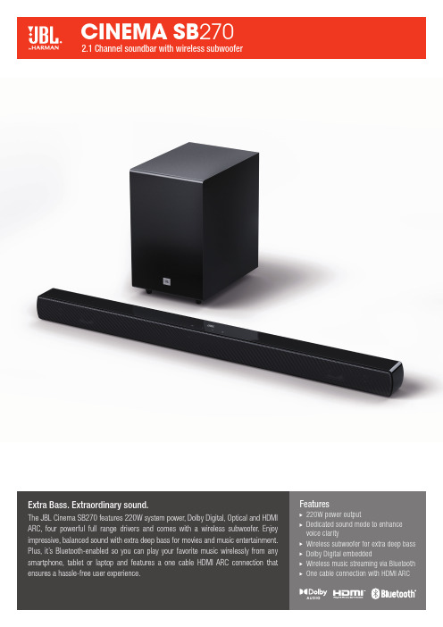
Extra Bass. Extraordinary sound.The JBL Cinema SB270 features 220W system power, Dolby Digital, Optical and HDMI ARC, four powerful full range drivers and comes with a wireless subwoofer. Enjoy impressive, balanced sound with extra deep bass for movies and music entertainment. Plus, it’s Bluetooth-enabled so you can play your favorite music wirelessly from any smartphone, tablet or laptop and features a one cable H DMI ARC connection that ensures a hassle-free user experience.Features220W power outputD edicated sound mode to enhance voice clarityW ireless subwoofer for extra deep bass D olby Digital embeddedW ireless music streaming via Bluetooth O ne cable connection with HDMI ARCHARMAN International Industries, Incorporated 8500 Balboa Boulevard, Northridge, CA 91329 USA © 2021 HARMAN International Industries, Incorporated. All rights reserved. JBL is a trademark of HARMAN International Industries, Incorporated, registered in the United States and/or other countries. The Bluetooth® word mark and logos are registered trademarks owned by Bluetooth SIG, Inc. and any use of such marks by HARMAN International Industries, Incorporated is under license. Other trademarks and trade names are those of their respective owners. The terms HDMI, the HDMI logo, and High-Definition Multimedia Interface are trademarks or registered trademarks of HDMI Licensing LLC in the United States and other countries. Les termes HDMI, le logo HDMI et High-Definition Multimedia Interface sont des marques commerciales ou des marques commerciales déposées de HDMI Licensing LLC aux États-Unis et dans d’autres pays. Dolby, Dolby Audio and the double-D symbol are trademarks of Dolby Laboratories. Dolby, Dolby Audio et le symbole du double D sont des marques commerciales de Dolby Laboratories. Features, specifications and appearance are subject to change without notice.Features and Benefits220W power outputIncredible, powerful sound for an immersive cinematic experience.Dedicated sound mode to enhance voice clarityJust press the “Voice” button on the remote control to enhance voice clarity, and never miss a word of your favorite movie.Wireless subwoofer for extra deep bassEnjoy deep and thrilling bass and clutter-free experience.Dolby Digital embeddedDolby Digital embedded for ultimate movie experience.Wireless music streaming via BluetoothStream and enjoy all your music wirelessly from any mobile device.One cable connection with HDMI ARCThe one cable H DMI ARC connection allows for the simplest set-up and a hassle-free user experience.What’s in the BoxSoundbarWireless subwooferRemote control with batteriesPower cords (up to 8pcs depending on region SKUs)HDMI cableWall-mount bracket kit with screwsQuick start guideWarranty cardSafety sheet Technical SpecificationsP ower supply: 100 – 240VAC, ~ 50/60Hz T otal speaker power output(Max. @THD 1%): 220WS oundbar power output (Max. @THD 1%): 2 x 52WS ubwoofer power output (Max. @THD 1%): 116WS oundbar transducer: 2 x (48 x 90)mm racetrack driver + 2 x 0.5" tweeterO perating temperature: 0°C – 45°CS ubwoofer transducer: 5.25", wireless sub H DMI Video output (With Audio return channel): 1H DMI HDCP version: 1.4M ax SPL: 82dBF requency response: 40Hz – 20kHzA udio inputs: 1 Optical, Bluetooth (USB is for Service only.)B luetooth version: 4.2B luetooth profile: A2DP V1.3/ AVRCP V1.5 B luetooth frequency range:2402MHz – 2480MHzB luetooth Max. transmitting power:<0dbm (EIRP)M odulation Type: GFSK, π/4 DQPSK2.4G Wireless frequency range:2400 – 2483MHz2.4G Max. transmitting power: 3dBmS oundbar dimensions (W x H x D):900 x 62 x 67 (mm) / 35.4" x 2.44" x 2.64" S ubwoofer dimensions (W x H x D):200 x 320 x 280 (mm) / 7.87" x 12.6" x 11" S oundbar weight: 1.65kgS ubwoofer weight: 5kg。
迈洛特克2702和3702记录器产品说明书

1981FEATURES AND SPECIFICATIONSMOLYTEK 2702 AND 3702 RECORDERS27023702REV: 03302004Standard Specifications for Model 2702 and 3702INPUTSNUMBER OF INPUTSUp to 32 analog inputs plus the computer I/O described in "computer interface" section on Page 4.TYPES OF INPUTSAny combination of any of the following types of analog inputs can be selected by the operator:Millivolts and Volts: Any full-scale voltage from +/-1 millivolt to 10 volts can be programmed.Current: 4 to 20 mA or other current ranges such as 1 to 5 mA or 10 to 50 mA can be accommodated by simply installing a resistor across the input terminals.Thermocouples: Linearization to 0.2°C conformity with NBS reference monographs plus automatic cold junction compensation are provided for thermocouple types J, K, T, R, S, E, B, N, Plaintell II, W/W-26Re. In addition, linearization for special thermocouples such as Xk, XA, EU-2, LB-3 etc. can be entered by the operator. Cold junction temperature is continuously monitored and automatically compensated for in all TIC measurements, but can be disabled for specific channels when not required.Resistance Temperature Detectors (RTDs): Linearization is provided for Pt-1 00, both DIN 43760 (IEC 200385) and Alpha .003923; 120 ohm Nickel, Edison Electric Institute 120 ohm at 0°C; 10 ohm Copper, Edison Electric Institute 10 ohm at 0°C; 10 ohm Copper at 25°C. Any curve, such as PT -50 or JIS 2003916, can be entered by the operator.Relative Humidity: Relative humidity is calculated using dry and wet bulb temperatures as variables in a standard Rh algorithm.User Programmed Linearization: Room for 16 different customer entered linearizations for applications such as special TICs, RTDs, thermistors, humidity sensors, gas analyzers, load cells, flow meters, etc.This linearization may be entered as a look-up table with up to 40 break points, or with a slope/intercept using the equation y = Mx + b.T/C STANDARDIZATIONOne step software routine references up to 31 thermocouples of the same type to within +/-0.15°C. This routine will solve thermocouple reading inaccuracies due to unmatched T/Cs of the same type, different sensor lead lengths, or temperature gradients across the input terminals.SCAN CYCLE TIMEAll input signals and 2 alarm set points per channel are scanned every 2 seconds regardless of chart speeds or datalog intervals.ENGINEERING UNITSAny three character engineering unit can be created and assigned to correspond with any scaling factor on any channel. Units such as GPM, T/D, RPM, MIL, TON, KG, etc. can be assigned to channels. These units will be included in the computer output, digital display and printed on the chart when datalogging.SCIENTIFIC NOTATIONInput values exceeding five digits can be expressed in scientific notation on the chart, digital displaysand serial output. For example, 0.000061 TOR would be represented as 6.1 X 10⁻⁵.PROGRAMMABLE RESOLUTIONFor datalog, serial ASCII and digital displays; one or five places to the right of the decimal may be selected.Page 1 of 8ALARM OPERATIONALARM SET POINTSEach channel includes 2 set points that can be used to indicate high/low, high/higher, low/lower or rate of change alarms. Set points can be programmed along any range in any engineering units.ALARM TREND PRINTINGWhen any channel exceeds an alarm set point, the date and time are printed on the chart and brackets (< >) will appear around the ID number of the channel involved until the alarm condition ends. The date and time will also be printed when the alarm ends.ALARM DATALOGGINGOne normal and one fast rate can be programmed for datalog printing with the faster interval occurring during alarm conditions. An H for high alarm or an L for low alarm will follow the channel ID number of the channels in alarm.ALARM CHART SPEEDThe operator may select a slow chart speed for normal operating conditions and a second, faster speed for alarm conditions. The faster chart speed will automatically engage whenever one or more channels exceed a high or low alarm setting. The date and time will be printed when the recorder switches to alarm speed and when the alarm condition has cleared. The unit will return to the normal speed when the alarm has cleared.RATE OF CHANGE ALARMThe rate at which any input changes over a programmable period of time can be displayed on any channel. As with every other channel, this channel will have two programmable set points.ALARM BUZZERA built in alarm buzzer will beep every 2 seconds as long as any alarm condition continues or until silenced from the keyboard.ALARM SCAN FREQUENCYAll 64 alarm set points (2 per channel) are automatically scanned every 2 seconds.ALARM MESSAGES12 messages of 16 characters each can be composed and assigned to specific set points. A message can then be printed whenever its assigned set point is activated. These messages may contain instructions for the operator such as "CHECK COOLANT" or "CALL EXT. 9030" or the message may identify the nature of the alarm, such as "HI TEMP OVEN #3."ALARM RELAYS (OPTIONAL)The recorder is available with optional 12, 24, or 32 alarm relays. Relays are S.P.D. T. and can be assigned to any individual or group of set points using And/Or logic. Contacts can be programmed for N.O. or N.C. operation and are rated at 5.0A @ 24 VDC or 120 V AC for resistive loads; 0.1 A @ 120 VAC for inductive loads.AUTOMATIC/MANUAL PHONE DIALINGAny telephone number plus area and access codes (up to 18 digits) can be stored for automatic dialing and communication with a remote location via modem connection any time a channel goes into alarm (telephone modems are required). After a connection is made, data will be transmitted for 30 minutes or for the duration of the alarm before automatic disconnect.Page 2 of 8COMPUTER INTERFACEA complete two-way RS-232 and 20 mA current loop interface is standard in every 2702. The output is programmable and can contain date and time as well as alarm status, measured variable and engineering units. Data transmission can include all channels, selected channels or only channels in alarm. Data can be transmitted to a connected computer, printer, terminal or data storage device at any interval from continuous to once every 7 days (168 hours). A connected computer can also query instruments for data on demand in channel by channel or in binary block formats for use in computer or PLC controlled data acquisition applications. Parity and stop bits are programmable and 15 baud rates can be selected from 50 through 19.2K.SERIAL OUTPUT ON ALARMEach channel can be programmed to appear in the computer output: 1) continuously, 2) never; 3) only when that particular channel is in an alarm condition.TAGLINES IN COMPUTER OUTPUTInstruments can be programmed to include or exclude 6 character taglines for channel identification in the serial output. MATH CALCULATIONSFLOATING POINT ARITHMETICFloating point addition, subtraction, multiplication and division between any two channels can be displayed on athird (virtual) channel. This virtual channel can itself be a part of any calculation.DOUBLE INTERPOLATIONData values on real and virtual channels can be manipulated by feeding them through multiple linearization tables and/or math routines. This feature allows channels to accept the conditioned value of another input channel as a direct input.SQUARE ROOTThe square root of any input can be extracted and displayed. The unit can trend, log and/or transmit up to 32 square root extractions.TIME AVERAGINGThe averages of up to 8 different inputs over a programmed time interval from 24 minutes to 254 hours can be calculated with an automatic reset after the selected interval.GROUP AVERAGINGThe average of any group of 2 to 31 channels can be calculated and displayed as a separate channel. Two or more group averages can be determined simultaneously.INTEGRATIONSamples of any input taken once per second are added and displayed until the programmed reset value has been reached. Operator may select a threshold level for exclusion of lesser input values.RATE OF CHANGEMonitors, records and transmits the rate of change of an input over a specified time period from 1 min. to 254 hours.MASS FLOWMass flow is calculated using the algorithm shown below and displayed as a separate input.FOCalculates the lethality factor of a temperature input monitoring a steam sterilization process. Internally calculates the total equivalent time at a base temperature derived from the actual real time temperature.Page 3 of 8PRINTINGTREND PRINTINGThe unit plots a data point (representing the input value) for each active channel with every excursion of the print head over the chart. The continuous series of these points forms a trend line. A channel ID number or three-character tag will appear to the right of the trend lines.DATALOGGINGInput signal data including engineering units and alarm status for all active channels plus date and time will be printed in a column format. The unit prints data in five columns (3 columns if tags are printed).The frequency of printing is adjustable from once every 12 seconds to once every 5000 minutes.TREND RECORDING AND DATALOGGINGAny combination of channels can be trend recorded, datalogged or both with individual control over each channel. Printing can also be set up for automatic interruption of trend recording with a datalog print of all input signals and then a return to trend recording. Switch from trend recording to datalog can be programmed to occur from once every minute to once every 168 hours and/or whenever an alarm occurs on any channel.ALARM TREND RECORDING AND DATALOGGINGAs an alternative to continuous recording or logging each channel can be programmed to appear in the trend or datalog printing only when it is in alarm. For example, channels 1 to 15 may be programmed for continuous recording, with channels 16, 18 and 20 to be printed on the chart only when they exceed their alarm set points.PROGRAMMABLE PRINT DARKNESSOne of four keyboard settings can be selected for optimum print contrast.DOT FILLINGThe dot filling feature produces a continuous trend line even if an input signal changes 100% of full scale in a few seconds.MINIMUM / MAXIMUMA digital print-out of min. and max. input values for each active channel over a programmable time period can be selected with automatic reset after print.REPORT GENERATIONA single keystroke activates a printout of real time plus min/max values with units of measure for all channels programmed for datalog printing.MESSAGE PRINTINGMessages typed on the keyboard can be printed on the chart or sent to a peripheral computer, terminal or printer via the serial port. Single line message length can be up to 109 characters. Computer generated messages received via the ASCII port can also be printed on the chart.CHART SCALE PRINTINGA user designed measurement scale can be stored for printing at regular intervals. Scale can be made up of any numbers, symbols and/or characters.DATE/TIME REFERENCEThe day, month, year, hour, minute and second are printed on the chart at user programmed intervals while trending or at the beginning of each datalog print interval. The data and time print also occurs automatically at the onset and clearing of an alarm condition.CHART SPEEDSKeyboard selectable from 0.01 "/hour to 120"/hour or 0.02 cm/hour to 300 cm/hour in 0.01 increments.PRINT CYCLE TIME32 channels can be printed in less than six seconds. Channel ID or tag, chart scale, date and time are printed at all chart speeds.AUTO CHART DRIVE SHUT-OFFA paper counter will monitor the length of chart paper on the feed roll and automatically switch the chart drive to standby if the supply drops below 5 ft. The alarm buzzer will sound and a message will be shown on the digital displays indicating that replacement is necessary.Page 4 of 8FEATURES AND RELIABILITYACCURACYBetter than 0.1% of the amplifier full scale ranges for +/-1 0 mV, +/-100 mV, +/-1 V, + 10 V ranges; better than 0.5% for +/-1 mV. These accuracy figures are based on a percentage of the amplifier full scale, not on a percentage of the trend record display.WARRANTYFull 2 year warranty, parts and labor; F.O.B. factory.AUTOMATIC RESTARTIf power failure occurs, unit automatically resumes operation and computer communication when power is restored.SURGE WITHSTANDCertified for surge withstand capability to IEEE standard 472-1974.AUTOMATIC CALIBRATIONA built-in precision reference source automatically checks both zero and span (full scale) every 2 seconds and makes adjustments if needed.SEISMIC QUALIFIED2702 passed OBE and SSE tests.SECURITYA three-digit security code can be programmed to prevent any unauthorized entries from being made in program routines.MEMORY PROTECTIONAll programs and the clock are protected against power loss by internal battery and individual battery-backed chips. Recorder can be disconnected from the power line for 5 years without loss of memory or clock time.SIGNAL IDENTIFICATIONCHANNEL IDENTIFICATIONAny number from 0 to 99 may be used to identify input channels. The channel ID number is printed at intervals from 1/1 0" to 10" and to the right of the trend line it represents. This number will never be printed over another number where channels are intersecting or superimposed.TAGLINESUp to 32 taglines of 6 characters each can be created and assigned to channels for explicit identification. Taglines will appear after the engineering unit while datalogging and on the right section display if the channel is programmed for display. The first three characters of the taglines assigned to channels may be printed in place of channel ID number when trend recording.INSTRUMENT IDENTIFICATION CODEUp to 5 characters may be stored as an identification code. This ID code will appear after the date/time reference in the computer output and to the right of date/time reference on the chart.Page 5 of 8DIGITAL DISPLAYContinuous or sequential large character display on the front panel of time of day plus channel number, alarm status, up to 5 digits of data with + or -sign and engineering units of any channels.PROMPTINGRecorder is easy to program with prompted menu steps displayed in English on the digital displays.TAGLINES ON RIGHT DISPLAYAssigned taglines can be displayed on the right side display to correspond with associated channels programmed for automatic or manual display on the left section. The left section will show channel input level with the corresponding tagline shown on the right section.CLOCKContinuous digital display of the time of day. The battery backed up clock oscillator will maintain correct time during power outages of up to 5 years.ALARM DISPLAYWhen any channel exceeds one of its alarm set points the right section digital display will show the channel number, high or low alarm, up to 5 digits of data with + or -sign and the engineering unit such as C, F, LPM, GPM, etc. If several channels are in alarm at the same time the display will show each channel in turn for 2 seconds. The right display can be programmed to show either the alarm status of all channels turned on, or to present associated taglines of channels that are being displayed on the left section. If one of the optional alarm relays has been activated in either display format, that relay number will be displayed in far right of right digital display.Page 6 of 8COMMON MODE VOLTAGE170 VAC RMS channel to ground with optional high common mode input board. +/-15 volt maximum with standard input board.DIELECTRIC STRENGTH1,000 V power transformer primary ground; 1,000 V relay contacts to ground; 1,000 V power transformer primary to sensor input terminals.COMMON MODE REJECTION RATIOBetter than 120 db.INPUT IMPEDANCEGreater than 1 Megohm at DC.NORMAL MODE REJECTION RATIOBetter than 45 db at 60 Hz; 70 db at 1 KHz.POWER REQUIREMENTSLess than 100 watts peak power; 50 watts average power. Selector switch for 100, 115, 220 or 240 volts. Operates on either 50 or 60 Hz.OPERATING TEMPERATURE32°F to 140°F (0 to 60°C); 5% to 98% noncondensing relative humidity.MOUNTING2702 has rubber feet for bench top applications and flanges for 19" rack mounting. Jack screws for panel mounting are available as an option. Panel cutout dimensions are 10.125" H X 17.062" W (+0.06/- 0.0), metric: 25.72 cm H X 43.34 cm W (+ 1.5/-0.0).CHASSIS SLIDESEntire chassis slides out and removes for easy access. The rear panel is hinged and removable also.DIMENSIONS17.75" (45 cm) wide X 10.5" (26.7 cm) high X 15.5" (39.74 cm) front to back.WEIGHTNet 48 Ibs. (21.8 kg). Shipping weight 57 Ibs. (26 kg).Page 7 of 8COMMON MODE VOLTAGE170 VAC RMS channel to ground with optional high common mode input board. +/-15 maximum with standard input board.DIELECTRIC STRENGTH1000V power transformer primary to ground: 1000V relay contacts to ground; 1000V power transformer primary to sensor input terminals.COMMON MODE REJECTION RATIOBetter than 120db.INPUT IMPEDANCEGreater than 1 Megohm at DC.NORMAL MODE REJECTION RATIOBetter than 45db at 60 Hz; 70db at 1 KHz.POWER REQUIREMENTSLess than 100 watts peak power; 50 watts average power. Specify 110' 115, 220, or 240 V AC operating voltage when ordering. Operates on 50 or 60 Hz.OPERATING TEMPERATURE32°F to 140F (0 to 60°C); 5% to 98% noncondensing relative humidity.DIMENSIONS17" (43.2 cm) wide x 15.125" (38.4 cm) high x 11.35" (28.8 cm) front to back.WEIGHTNet 28.5Ibs. (12.9 kg). Shipping weight 41Ibs. (18.6 kg).Page 8 of 8。
HZ-V270说明书

控制面板
控制面板 控制面板上各按键的使用方法详见“操作指南”。
-6-
HZ-V270 连接面板 与其它设备的连接方法,请参考第 10 页。
后面板
1
AUDIO OUT
2
VIDEO OUT
3
S-VIDEO
4
AUDIO IN
5
VIDEO
6
PROJECTOR
7
OUT
8
COMPUTER
9
IN
10
5V- IN
AUDIO IN
-8-
HZ-V270 打开展示台 1. 用手向上轻拉镜头支杆,将镜头支杆竖起来。
2. 将镜头和臂灯展开到合适的位置。
臂灯
3. 将电源适配器插入展台后面板上的 5V 电源 IN 接口,接通电源,打开电源开关,即可 开始工作(控制面板上的“POWER”指示灯亮)。 注意:各活动部件达到限定位置后,请勿再强行扳动,否则容易损坏机器以及造成操作 者受伤。-2- HZ-V270产品特点
鸿合数码展示台是一款采用数字视频技术,用于各类实物、文本、图表、幻灯片及透明 胶片演示的视频采集设备,可连接电视机、投影机、电脑等多种多媒体设备,并可控制 投影机开关、切换,是多媒体演示、电化教学等信息传播中不可缺少的组成部分。 产品特征 鸿合数码展示台有以下特点: 易于连接 该展示台集镜头、视频处理及电源于一体,将展示台与显示器连接即可使用。 图像效果出色 该展示台采用高像素专业镜头,图像效果更出色。 使用方便 在展台未接通电源时,“COMPUTER IN”接口的信号可以直接输出到“COMPUTER OUT” 接口,电脑可以在展台不开机的情况下正常使用。 易于调节 焦距、光圈、白平衡等自动设定。也可以手动调节每一项参数,达到所希望的图像效果。 自动聚焦迅速 自动聚焦在 1~2 秒钟内完成。 22 倍光学放大镜头 22 倍的放大使摄像范围增大。 图像冻结 可使用冻结功能捕捉单帧图片。 多画面功能 可同时显示多幅图片,也可显示单帧图片。 图像旋转 图片可旋转 90°,180°,270°。 灵活的机械旋转结构 可倾斜的镜头支杆,镜头可在垂直方向旋转 330°,使摄像范围增大。
LOCTITE 270产品说明书

Technical Data SheetLOCTITE®270™(TDS for new formulation of Loctite®270™) December2013 PRODUCT DESCRIPTIONLOCTITE®270™provides the following productLOCTITE®270™is designed for the permanent locking andsealing of threaded fasteners.The product cures whenconfined in the absence of air between close fitting metalsurfaces and prevents loosening and leakage from shock andvibration.LOCTITE®270™is particularly suited for heavy dutyapplications such as studs into motor housings,nuts onto studsin pump housings and other fasteners where high strength isrequired.LOCTITE®270™provides robust curingperformance.It not only works on active metals(e.g.brass,copper)but also on passive substrates such as stainless steeland plated surfaces.The product offers high temperatureperformance and oil tolerance.It tolerates minor surfacecontaminations from various oils,such as cutting,lubrication,anti-corrosion and protection fluids.NSF InternationalRegistered to NSF Category P1for use as a sealant wherethere is no possibilty of food contact in and around foodprocessing areas.Note:This is a regional approval.Pleasecontact your local Technical Service Center for moreinformation and clarification.TYPICAL PROPERTIES OF UNCURED MATERIALSpecific Gravity@ 25°C 1.1Flash Point-See SDSViscosity,Brookfield -RVT, 25°C,mPa·s(cP):Spindle2,speed20rpm,400 to600LMSViscosity,Cone&Plate,25°C,mPa·s(cP):Cone C60/1°Ti@shear rate 129s-1450TYPICAL CURING PERFORMANCECure Speed vs.SubstrateThe rate of cure will depend on the substrate used. The graphbelow shows the breakaway strength developed with time onM10steel nuts and pared to different materials andtested according to ISO10964.%ofFullStrengthonSteelCure Time100806040201min5min10min30min1h3h6h24h72hBrassStainlesssteelZinc dichromateCr free, Zinc organicSteelCure Speed vs.Bond GapThe rate of cure will depend on the bondline gap. Gaps inthreaded fasteners depends on thread type,quality and size.The following graph shows shear strength developed with timeon steel pins and collars at different controlled gaps and testedaccording to ISO10123.%ofFullStrengthonSteelCure Time1007550251min5min10min30min1h3h6h24h72h.5mm.15mm.25mmCure Speed vs.TemperatureThe rate of cure will depend on the temperature.The graph below shows the breakaway strength developed with time at different temperatures on M10steel nuts and bolts and tested according to ISO 10964.% o f F u l l S t r e n g t h o n S t e e lCure Time1007550251min5min10min 30min 1h3h 6h 24h 72h5°C22 °C40 °CCure Speed vs.ActivatorWhere cure speed is unacceptably long,or large gaps are present,applying activator to the surface will improve cure speed.The graph below shows the breakaway strength developed with time on M10zinc dichromate steel nuts and bolts using Activator 7471™,7649™,7088™and 7091™and tested according to ISO 10964.% o f F u l l S t r e n g t h o n S t e e lCure Time1008060402001min5min10min 30min 1h3h6h24h 72h7471™7649™7088™7091™N oA c t iv a t o rTYPICAL PERFORMANCE OF CURED MATERIALAdhesive PropertiesCured for 24 hours @22°CBreakaway Torque,ISO 10964,Unseated:M10 steel nuts and bolts N·m 33(lb.in.) (290)M6 steel nuts and bolts N·m 5(lb.in.) (45)M16 steel nuts and bolts N·m 90(lb.in.) (800)3/8x 16steel nuts (grade 2) and bolts (grade 5) N·m 31 (lb.in.) (275)Prevail Torque @180°,ISO 10964,Unseated:M10 steel nuts and bolts N·m 33(lb.in.) (290)M6 steel nuts and bolts N·m 3(lb.in.) (26)M16 steel nuts and bolts N·m 125(lb.in.) (1,100)3/8x 16steel nuts (grade 2) and bolts (grade 5) N·m 33 (lb.in.) (290)Breakloose Torque,ISO 10964,Pre-torqued to 5N·m:M10 steel nuts and bolts N·m 39(lb.in.) (345)3/8x 16steel nuts (grade 2) and bolts (grade 5) N·m 35 (lb.in.) (310)Prevail Torque @180°,ISO 10964,Pre-torqued to 5N·m:M10 steel nuts and bolts N·m 25(lb.in.) (220)3/8x 16steel nuts (grade 2) and bolts (grade 5) N·m 31 (lb.in.) (275)Compressive Shear Strength, ISO 10123:Steel pins and collars N/mm² ≥9.0LMS(psi) (≥1,305)Cured for 1 week @22ºC,Breakloose Torque,ISO 10964,Pre-torqued to 5N·m:M10 zinc phosphate nuts and bolts N·m 46(lb.in.) (400)M10 stainless steel nuts and bolts N·m 30(lb.in.) (265)TYPICAL ENVIRONMENTAL RESISTANCECured for 1 week @22°CBreakloose Torque,ISO 10964,Pre-torqued to 5N·m:M10 zinc phosphate steel nuts and boltsHot StrengthTested at temperature% S t r e n g t h @ 22 °CTemperature, °C120100806040200050100150200Heat AgingAged at temperature indicated and tested @22°C% I n i t i a l S t r e n g t h @ 22 °CExposure Time, hours1251007550250010002000300040005000100 °C120 °C150 °C180 °C200 °CHeat Aging/Hot StrengthAged under conditions indicated and tested at temperature% I n i t i a l S t r e n g t h @ 22 °CExposure Time, hours120100806040200010002000300040005000100 °C120 °C150 °C180 °C200 °CChemical/Solvent ResistanceAged under conditions indicated and tested @22°C.%of initial strength Environment °C 500h1000h 5000h Motor oil125657575Unleaded gasoline 22909595Brake fluid 22105105100Water/glycol 50/5087758590Acetone 229595100Ethanol 22959595E85Ethanol fuel 22959595B100Bio-Diesel22100100110Breakloose Torque,ISO 10964,Pre-torqued to 5N·m:M10Stainless steel nuts and bolts%of initial strength Environment°C 500h1000h 5000h Sodium Hydroxide,20%22756555Phosphoric Acid,10%221009565GENERAL INFORMATIONThis product is not recommended for use in pure oxygen and/or oxygen rich systems and should not be selected as a sealant for chlorine or other strong oxidizing materials.For safe handling information on this product,consult the Safety Data Sheet (SDS).Where aqueous washing systems are used to clean the surfaces before bonding,it is important to check for compatibility of the washing solution with the adhesive. In some cases these aqueous washes can affect the cure and performance of the adhesive.This product is not normally recommended for use on plastics (particularly thermoplastic materials where stress cracking of the plastic could result). Users are recommended to confirm compatibility of the product with such substrates.Directions for use:For Assembly1.For best results,clean all surfaces (external and internal)with a LOCTITE ® cleaning solvent and allow to dry.2.If the cure speed is too slow,use appropriate activator.Please see the Cure Speed vs.Activator graph for reference.Allow the activator to dry when needed.3.To prevent the product from clogging in the nozzle,do notallow the tip to touch metal surfaces during application.4.For Thru Holes ,apply several drops of the product ontothe bolt at the nut engagement area.5.For Blind Holes ,apply several drops of the product to thelower third of the internal threads in the blind hole,or the bottom of the blind hole.6.For Sealing Applications ,apply a 360°bead of productto the leading threads of the male fitting,leaving the first thread free. For bigger threads and voids,adjust product amount accordingly and apply a 360°bead of product on the female threads also.7.Assemble and tighten as required.For Disassembly1.Remove with standard hand tools.2.In rare instances where hand tools do not work becauseof excessive engagement length,apply localized heat to nut or bolt to approximately 250°C. Disassemble while hot.3.Apply localized heat to the assembly to approximately250°C. Disassemble while hot.For Cleanup1.Cured product can be removed with a combination ofsoaking in a Loctite solvent and mechanical abrasion such as a wire brush.Loctite Material Specification LMSLMS dated June26,2009. Test reports for each batch are available for the indicated properties. LMS test reports include selected QC test parameters considered appropriate to specifications for customer use. Additionally,comprehensive controls are in place to assure product quality and consistency. Special customer specification requirements may be coordinated through Henkel Quality.StorageStore product in the unopened container in a dry location. Storage information may be indicated on the product container labeling.Optimal Storage: 8°C to21°C. Storage below8°C or greater than28°C can adversely affect product properties Material removed from containers may be contaminated during use. Do not return product to the original container. Henkel Corporation cannot assume responsibility for product which has been contaminated or stored under conditions other than those previously indicated.If additional information is required, please contact your local Technical Service Center or Customer Service Representative.Conversions(°C x1.8)+32=°FkV/mm x25.4=V/milmm/25.4=inchesµm/25.4=milN x0.225=lbN/mm x5.71=lb/inN/mm²x145=psiMPa x145=psiN·m x 8.851= lb·inN·m x0.738=lb·ftN·mm x0.142=oz·inmPa·s=cPNote:The information provided in this Technical Data Sheet(TDS)including the recommendations for use and application of the product are based on our knowledge and experience of the product as at the date of this TDS.The product can have a variety of different applications as well as differing application and working conditions in your environment that are beyond our control.Henkel is, therefore,not liable for the suitability of our product for the production processes and conditions in respect of which you use them,as well as the intended applications and results.We strongly recommend that you carry out your own prior trials to confirm such suitability of our product.Any liability in respect of the information in the Technical Data Sheet or any other written or oral recommendation(s)regarding the concerned product is excluded, except if otherwise explicitly agreed and except in relation to death or personal injury caused by our negligence and any liability under any applicable mandatory product liability law.In case products are delivered by Henkel Belgium NV,Henkel Electronic Materials NV,Henkel Nederland BV,Henkel Technologies France SAS and Henkel France SA please additionally note the following:In case Henkel would be nevertheless held liable,on whatever legal ground, Henkel’s liability will in no event exceed the amount of the concerned delivery.In case products are delivered by Henkel Colombiana,S.A.S.the following disclaimer is applicable:The information provided in this Technical Data Sheet(TDS)including the recommendations for use and application of the product are based on our knowledge and experience of the product as at the date of this TDS.Henkel is, therefore,not liable for the suitability of our product for the production processes and conditions in respect of which you use them,as well as the intended applications and results.We strongly recommend that you carry out your own prior trials to confirm such suitability of our product.Any liability in respect of the information in the Technical Data Sheet or any other written or oral recommendation(s)regarding the concerned product is excluded, except if otherwise explicitly agreed and except in relation to death or personal injury caused by our negligence and any liability under any applicable mandatory product liability law.In case products are delivered by Henkel Corporation,Resin Technology Group,Inc.,or Henkel Canada Corporation,the following disclaimer is applicable:The data contained herein are furnished for information only and are believed to be reliable.We cannot assume responsibility for the results obtained by others over whose methods we have no control.It is the user's responsibility to determine suitability for the user's purpose of any production methods mentioned herein and to adopt such precautions as may be advisable for the protection of property and of persons against any hazards that may be involved in the handling and use thereof.In light of the foregoing,Henkel Corporation specifically disclaims all warranties expressed or implied,including warranties of merchantability or fitness for a particular purpose,arising from sale or use of Henkel Corporation’s products.Henkel Corporation specifically disclaims any liability for consequential or incidental damages of any kind, including lost profits.The discussion herein of various processes or compositions is not to be interpreted as representation that they are free from domination of patents owned by others or as a license under any Henkel Corporation patents that may cover such processes or compositions.We recommend that each prospective user test his proposed application before repetitive use,using this data as a guide.This product may be covered by one or more United States or foreign patents or patent applications.Trademark usageExcept as otherwise noted,all trademarks in this document are trademarks of Henkel Corporation in the U.S.and elsewhere. ®denotes a trademark registered in the U.S.Patent and Trademark Office.Reference0.2。
- 1、下载文档前请自行甄别文档内容的完整性,平台不提供额外的编辑、内容补充、找答案等附加服务。
- 2、"仅部分预览"的文档,不可在线预览部分如存在完整性等问题,可反馈申请退款(可完整预览的文档不适用该条件!)。
- 3、如文档侵犯您的权益,请联系客服反馈,我们会尽快为您处理(人工客服工作时间:9:00-18:30)。
KT270系列驱动器参数设定
1、普通参数:
PA3=7 初始显示状态(转矩)
PA4=0 位置控制模式
PA5=70~90 速度比例增益
PA6=100 速度积分常数
PA7=0 加减速时间常数
PA8=100 速度检测低通滤波器
PA9=40~60 位置比例增益
若PA5=70,则PA9=40。
这两项数据越大,运行反映越快,但要配合好,否则会出现抖动和过载。
PA10=0 位置前馈增益
PA11=300 位置前馈低通滤波器截止频率
PA12=4 位置指令脉冲倍率分子
PA13=1 位置指令脉冲倍率分母
PA14=0 位置指令脉冲输入方式
PA15=0 位置指令脉冲方向取反。
若方向相反,就改为1。
PA16=100 定位完成范围
PA18=1 位置超差错误无效
PA19=0~2 位置指令平滑滤波器
PA20=1 行程末端输入无效
PA22=0 输入型号电平取反
PA34=150 内部正转转矩限制
PA35=-150 内部反转转矩限制
PA36=70 外部正转转矩限制
PA37=-70 外部反转转矩限制
PA38=70 试运行JOG运行转矩限制
PA39=70~100 电机电流检测阀值
PA55=0 多功能输入端口选择
PA56=0 多功能输出端口选择
PA57=0 输出信号电平改变
PA58=3 输入端子去抖动时间常数
2、KT270系列驱动器其它参数配置:
以下参数由驱动器和电机厂配合设置,用户可以查看,不要修改,有不符合的参数,请与三金技术人员联系。
注意:PA1、PA2、PA59和PA61号以上参数输入的不符合要求,将损害驱动器和烧坏电机!
1、查看修改PA1、PA2和PA59号参数,把PA0设置成385;查看修改PA61号以
上参数,把PA0设置成510;PA0出厂时为315,不能修改PA1、PA2和PA59,不能看PA61以上的参数。
2、130ST-M10020 伺服钳瓶用2KW伺服电机,KT270-H3-30驱动器。
3、130ST-M12020 伺服翻转用2.5KW伺服电机,KT270-G3-50驱动器。
4、130ST-M12020C 伺服平行剪切用2.5KW伺服电机,KT270-G3-50驱动器。
5、130ST-M12020B 伺服角剪2.5KW伺服电机,KT270-G3-50驱动器。
6、130ST-M07725开始时单滴料伺服钳瓶用2KW伺服电机,KT270-H3-30驱动
器。
7、180ST-M15020伺服冲料用伺服电机,KT270-E3-75驱动器。
8、KT270-H3-30驱动器,匹配各种规格电机下的参数。
电机型号:130ST-M10025 130ST-M10020 130ST-M12020 130ST-M07725
PA1 型号: 50 51 50
PA2 软件版本 4402 2165
PB5 参数版本 1090 1090 1070
PA59 控制板编号 2703 2703 2703
PA85 号参数: 1140 1090
PA23 最大速度 2400 2400
PA43速度指令输入增益 200 200
PA71转自惯量2140 2140 2180 1580
PA72 120
PA73额定转速2500 2000 2000 2500
PA74最高转速3000 2400 2400 3000
PA75额定电流92 68 85 72
PA76过载倍数160 210 250 200
PA86电流反馈控制 2225 2250
随PA1而变
9、KT270-G3-50驱动器,匹配各种规格电机下的参数。
电机型号:130ST-M10025 130ST-M10020 130ST-M12020 130ST-M07725 180ST-M15020 PA1 型号 50 50 51 48 24
PA2 软件版本2140 2140 2140 2100 2140
PB5 参数版本1090 1090 1090 1070 1090
PA71转自惯量2140 2140 2180 1580 4745
PA73额定转速2000 2000 2000 2500 2000
PA74最高转速2400 2400 2400 3000 2400
PA75额定电流92 68 85 72 105
PA76过载倍数170 170 170 200 230
PA86号参数:2250 2250 2250 2500 2250
10、KT270-E3-75驱动器配电机型号:180ST-M15020
PA1 号参数:驱动器型号:24
PA2 号参数:软件版本:2140
PA6 号参数:速度积分常数:80
PB5 号参数:参数版本:1090
PA59号参数: 2703
PA60号参数:零速转矩:15
PA71号参数:转子惯量:4745 ,表示4.7745(kgm2X103
PA72号参数:电机额定转矩
PA73号参数:额定转速:2000
PA74号参数:最高转速:2400
PA75号参数:电机额定电流:105 表示10.5A
PA76号参数,过载倍数限制值:230~250
PA86号参数,电流反馈系数:2250 (若3375 ,负载大)
非常抱歉我方没有回复你的问题。
与负载相关参数有如下几个:
1、PA86 电流反馈系数;
2、PA72 电机额定电流(或额定转矩,记不清了);
3、PA75 电机额定转矩(或额定电流,记不清了);要求是85,表示
4、PA76 过载倍数限制值;
5、PA71 转子惯量;
其中:PA72、PA75、PA86与负载关系较大。
PA1和PA59参数决定了固化参数表中对应的电机参数,包括了PA71、72、75、76、86等。
目前我怀疑最大可能是PA86参数,若用E-75驱动器,则该数值应该是3375,请帮助确认。
谢谢!
陈忠
关于您的问题现在答复如下(见红色字体):
1、PA86 电流反馈系数;要求是2250,表示什么意思?表示配50A驱动器
2、PA72 电机额定电流(或额定转矩,记不清了);表示电机的额定转矩
3、PA75 电机额定转矩(或额定电流,记不清了);表示电机的额定电流,85说明电机的额定电流是8.5A
要求是85,表示什么意思?
4、PA76 过载倍数限制值;
5、PA71 转子惯量;
要求是4745,表示什么意思?表示电机的转子惯量是4.745kgm2×10-3
杨文博
PA86与电流采样用的电阻数值有关:
H-20和H-30用了一个0.01欧姆电阻采样,PA86=为1125;
H-50用了2个0.01欧姆并联采样,故PA86=2*1125=2250;
H-75用了3个0.01欧姆并联采样,故PA86=3*1125=3375;。