列尾装置MKLW使用手册
列尾装置
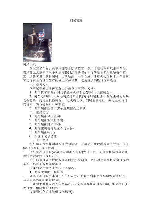
列尾装置列尾主机列尾装置全称:列车尾部安全防护装置,是用于货物列车取消守车后,在尾部无人职守情况下为提高铁路运输的安全性而研制的专用运输安全装置,设备应用计算机编码、无线遥控、语音合成、计算机处理技术,保证列车运行安全而设计生产的安全防护设备,也是重要的铁路行车设备。
一、系统构成列车尾部安全防护装置主要由以下三部分构成:1.列车机车部分:列尾装置司机控制盒(简称司机控制盒)。
2.列车尾部部分:列尾装置尾部主机(简称列尾主机)。
列尾主机的附属设备包括,列尾主机检测台、无线确认仪、列尾主机电池、列尾主机电池充电器、简易场强计、屏蔽室。
3.列车尾部安全防护装置数据处理系统。
二、主要功能1、列车尾部风压查询;2、列车尾部低风压告警;3、列车尾部排风制动;4、列尾主机电池电量不足告警;5、列车尾部标识;6、黑匣子记录功能。
三、工作原理机车乘务员操作司机控制盒功能键,首尾以无线数据传输方式传递信令(编码信息),其信令通过机车列调电台(或列尾专用机车电台)发送出去,列尾主机接收到司机控制盒发送的信令后,其响应信息再以同样的方式返回司机控制盒,司机通过司机控制盒合成的语音信息来了解列车尾部风压及列尾主机的工作状态等情况。
1.列尾主机的工作原理列尾主机内设有本机出厂ID 编号,安装于列车尾部车钩或提钩杆上,与列车尾部制动软管连接。
主要用于时时监测列车尾部风压、实现列车尾部排风制动、尾部标识(白天用红白相间斜彩条标识,夜间用红色发光管组闪光标识)。
列尾主机是封装于全封闭壳体内的系统。
由高集成微控制器系统、列尾装置运用数据记录、调制解调器、双余度电磁阀、电池组、电台、压力传感器、主风管等部件组成。
2.司机控制盒工作原理司机控制盒内设有本务机车的机车号码,有确认(即输号,黑键)、风压查询(绿键)、尾部排风(红键)、和列尾主机消号(黑键+绿键)等功能键;带有数码显示,待机状态时显示机车号码,查询时(或低风压告警时)显示列车的尾部风压,2秒钟后又显示机车号码;自带语音系统(即音频功放、扬声器)司机控制盒带有列尾装置运用数据记录(俗称,“黑匣子”),可滚动记录4 000 多条数据(即事件)。
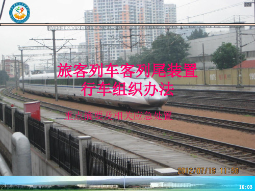
旅客列车客列尾装置行车组织办法(摘要及应急处置)
二、行车组织
图4
• 备注:1.联系方式包括GSM-R手持终端号和公网手机号。 2.本表一式两份,由车辆乘务员提供,并与本务机车司机共同 填写后各持一份,回乘后交车间值班室管理,保存期一个月。
16:41
二、行车组织
• (四)列车始发前、终到后及途中更换机车时,司机、车辆乘务员应 按规定建立、解除机车综合无线通信设备(下称CIR设备)与客车列 尾装置的通信连接关系。 • 1.旅客列车始发前或更换机车时,司机应根据客列尾ID信息联络卡, 在CIR设备上键入客车列尾装置主机的ID号码,建立CIR设备与客车 列尾装置主机的通信连接关系。连接成功后,客车列尾装置主机显示 与其连接的机车号。 • 联系用语如下: • 司机(呼叫):“XXXX次车辆乘务员,XXXXXX号列尾连接完毕, 确认机车号”。 • 车辆乘务员(应答):“XXXXXX号列尾,机车号XXXX”。 • 司机(应答):“XXXX次司机明白。”
16:41
二、行车组织
• 2.旅客列车终到或中途换挂机车摘车时,司机应 在列车停妥后立即解除与客车列尾装置主机的通 信连接。 解除与客车列尾装置主机连接后,司机应主 动联系车辆乘务员进行确认。联系用语如下: • 司机(呼叫):XXXX车次车辆乘务员,列尾 已经解除,请确认; • 车辆乘务员在检查确认客车列尾装置主机不 再显示机车号时,应答:XXXX次司机,列尾已经 解除。
• •
•
16:41
三、客车列尾装置应急处置
• (二)KLW主机与机车不能建立连接情况。 • 1. KLW通信连接故障行车应急处置办法。 • (1)KLW与CIR建立连接后司机查询尾部风压不正常。 收到司机通知查询尾部风压不正常时,车辆乘务员应 到达尾部客车KLW主机处呼叫司机进行手动查询风压操作, 并核对此时KLW主机显示风压数值与尾部客车风表显示风 压数值是否一致,如一致则通知司机KLW主机作用正常。 若尾部列车风表显示压力符合规定,但KLW主机显示尾部 风压不足时,应为KLW主机故障,通知司机按客车列尾装 置故障办理,更换KLW主机。
铁路客车列尾系统

4、排风制动
按排风键,LED显示PF
5、风压异常提示:
KLW 向
LBJ 发 送 风 压 异 常 信 息
扬声器发出提示音 LED显示风压
XXXX机车注意 风压XXX
按“确认”键应答,终止信息发送
显示风压
6、电压欠压提示:
KLW 向
LBJ 发 送 风 压 异 常 信 息
扬声器发出提示音 LED显示
四、列尾故障后,司机每个区间应至少查询列尾2次, 如连续2次查询列尾正常,可视为列尾系统恢复正常工 作,通知车辆乘务员,并在《运行日志》上记录恢复正 常的时间和区间
我们的目标是:心系怀机、以段为家 服务旅客、争先创优
怀 化 运 用 车 间
按“确认”解除语音 提示,但LED正常显示
每1秒显示一次 报警公里标
Hale Waihona Puke 四、报警操作• 5、报警解除 接收到报警解除信息时:
XXX公里道口报警解除,注 意运行
XXX公里线路报警 解除,注意运行
注意:LBJ连续30秒以上未再次
收到报警信息,恢复为守候状 态
XXX次列车/(机车)报 警解除,
注意运行
五、出入库检测
2、销号
注意:
不入客技所检修, 在车站立折的旅客列车, 试风后再销号
在中间站立折的 旅客列车,机车 和列尾ID不变, 可不销号
XX列尾装置 销号成功
输入6个“0”
四、报警操作
1、发送列车防护报警
启动列车防护报警
解除列车防护报警
注意:由主机发起的列车防护报警,按控制盒报警键不能解除
四、报警操作
• 2、接收报警(列车防护)
LED 指示灯亮
未与列尾连接, 显示机车号
交大路通列尾装置PPT课件

• 列车管压(即500/600KPa)自动识别;
• 特有信息显示视窗;
• (1)上电时,显示列尾主机ID编号、电池电压、电池容量、当前机车号码;
• (2)运行当中显示相应运用功能信息,如功能提示符号、数据等;
• (3)列检测量尾部风压显示;
• 列检测风功能,列车管压数码显示;
• 断电保存机车号码、程序置入设备出厂ID号等功能;
背面
通话/列尾转换开关
第19页/共70页
(九) WTSM-2(3)型司机控制盒检测仪
• 集手持电台、信令系统于一 体;
• 电池供电; • 对讲通话功能,可呼叫与之
相同频率的机车无线列调电 台; • 用于检测司机控制盒的确认 (即输号)、消号、查询风
第20页/共70页
(十)列尾装置输号器
• 设置司机控制盒机车号码; • 查看/设置司机控制盒时间。
第7页/共70页
(一) HBLT-Ⅱ(S)型列尾主机
第8页/共70页
• 高科技合成材料结构,模具成型,防锈蚀、耐受湿热及剧烈震动、坚固耐用;
• 挂钩采用不锈钢材料,防锈蚀。列车上安装方式:两种安装方式,可牢固的安 装在各种车钩上或提钩杆上(出厂前选择)。
• 深孔防盗锁具防撬防拨、钥匙防误操作设计;
和时钟进行手动校准; • 本机机车号码可手动设置,并可按确认键对列尾主机输入当前设置的
机车号码; • 有手动检测和自动检测两种工作模式,用户可根据实际需要进行列尾
主机的功能及电性能指标检测,并自动判定检测结果是否合格; • 可自动滚动存储2044条检测数据,始终保留最近检测的数据,并可
将所存储的数据上传到计算机中显示、检索和打印。即具有“黑匣子” 功能。 • 特有信息显示视窗,可清晰、直观地实时显示检测数据,并自动对合 格与不合格项进行标识; 第13页/共70页
列尾装置运用基础管理系统

列尾装置运用管理一、列车尾部安全防护装置(简称列尾装置)(一)列尾装置功能标示列车尾部标志、检查风压、排风制动、主管风压非正常自动报警等功能。
1、作为列车标志,提示列车整列达到。
2、自动反馈列车制动与缓和状态。
3、对列车尾部风压、制动主管泄露、制动软管断裂、折角塞门意外关闭实行全程监控。
4、避免机车错挂。
(二)列尾装置构成由固定在机车司机室内旳司机控制盒和安装在列车尾部旳列尾主机及附属设备构成。
列尾装置设备及其配套设施涉及:列尾主机及钥匙、测试台及钥匙、充电器、电池、机车号确认仪、列尾主机及司机控制盒数据下载仪、专用电脑、列尾司机控制盒、一体化控制盒、列尾中继器、维修专用工具。
1、ZTF3688型一体化列尾控制盒采用“双向数传”工作方式,便携式电台设计,监听列尾作业、对列尾主机置号、控制下载“黑匣子”数据、校对时钟、呼喊通话。
2、ZTF3688型机车号确认仪采用便携式设计,列尾作业员将机车号输入列尾主机中,提前建立“一对一”关系;对主机置号,兼有呼喊机车、车站以及对讲通话;针对ZTF及02-6型完毕校对时钟及下载02型主机“黑匣子”数据功能。
3、ZTF型列尾固定和移动中继器列尾固定中继器重要解决在无线列调弱场区或列调作业繁忙区,列尾信号传递受阻而设计;列尾移动中继器安装在列车上,重要用于解决列尾装置在列车行进中旳弱场问题。
4、列尾主机数据下载仪和列尾司机控制盒数据转储器用于下载或转储“黑匣子”数据并至PC机。
5、ZTF3688型数字场强仪器采用便携式设计,重要用于无线列调和列尾装置所使用频段旳场强检测(测试主机电台发射功率),并呼喊机车、车站以及对讲功能。
二、列车尾部安全防护装置维护管理(一)车务段负责列尾主机、测试仪、机车号确认仪、电池充电器旳表面清洁、器件紧固完好无损、按键良好、显示正常。
具体内容:1、列尾装置、列尾主机测试仪、机车号确认仪旳平常维护、使用。
2、列尾主机检测、安装、拆卸、取送、平常保管。
Lincoln MAGNUM 250 LX SPOOL GUN 用户手册说明书

Operator’s ManualRegister your machine:/registerAuthorized Service and Distributor Locator: /locatorIM887| Issue D a te Apr- 14K Number:K2490-1Save for future referenceDate PurchasedCode: (ex: 10859)TABLE OF CONTENTSSAFETY PRECAUTIONS . . . . . . . . . . . . . . . . . . . . . . . . . . . . . . . . . . . . . . . . . . . . . . . . . . . . . . . . . . . . . . . . . . . . . . . . . . . . . . . . . . . . . . . . . . . . . . . . . . . . . . . . . . . . . . . . . . . . . . . . . . . . . . . . . . . . . . . . . . . . . . . . . . . . . . . . . . . . . . . . . . . . . . . . . . . . . . . . . . . . .i-v TABLE OF CONTENTS . . . . . . . . . . . . . . . . . . . . . . . . . . . . . . . . . . . . . . . . . . . . . . . . . . . . . . . . . . . . . . . . . . . . . . . . . . . . . . . . . . . . . . . . . . . . . . . . . . . . . . . . . . . . . . . . . . . . . . . . . . . . . . . . . . . . . . . . . . . . . . . . . . . . . . . . . . . . . . . . . . . . . . . . . . . . . . . . . . . . . .1 GENERAL INFORMATION . . . . . . . . . . . . . . . . . . . . . . . . . . . . . . . . . . . . . . . . . . . . . . . . . . . . . . . . . . . . . . . . . . . . . . . . . . . . . . . . . . . . . . . . . . . . . . . . . . . . . . . . . . . . . . . . . . . . . . . . . . . . . . . . . . . . . . . . . . . . . . . . . . . . . . . . . . . . . . . . . . . . . . . . . . . . . . . . . .2 PRODUCT DESCRIPTION . . . . . . . . . . . . . . . . . . . . . . . . . . . . . . . . . . . . . . . . . . . . . . . . . . . . . . . . . . . . . . . . . . . . . . . . . . . . . . . . . . . . . . . . . . . . . . . . . . . . . . . . . . . . . . . . . . . . . . . . . . . . . . . . . . . . . . . . . . . . . . . . . . . . . . . . . . . . . . . . . . . . . . . . . . . . . . . . . . .2 SPECIFICATIONS . . . . . . . . . . . . . . . . . . . . . . . . . . . . . . . . . . . . . . . . . . . . . . . . . . . . . . . . . . . . . . . . . . . . . . . . . . . . . . . . . . . . . . . . . . . . . . . . . . . . . . . . . . . . . . . . . . . . . . . . . . . . . . . . . . . . . . . . . . . . . . . . . . . . . . . . . . . . . . . . . . . . . . . . . . . . . . . . . . . . . . . . . . . . . . .2 RECOMMENDED PROCESSES AND EQUIPMENT . . . . . . . . . . . . . . . . . . . . . . . . . . . . . . . . . . . . . . . . . . . . . . . . . . . . . . . . . . . . . . . . . . . . . . . . . . . . . . . . . . . . . . . . . . . . . . . . . . . . . . . . . . . . . . . . . . . . . . . . . . . . . . . . . . . . . . . . . . . . . . . .2 INSTALLATION . . . . . . . . . . . . . . . . . . . . . . . . . . . . . . . . . . . . . . . . . . . . . . . . . . . . . . . . . . . . . . . . . . . . . . . . . . . . . . . . . . . . . . . . . . . . . . . . . . . . . . . . . . . . . . . . . . . . . . . . . . . . . . . . . . . . . . . . . . . . . . . . . . . . . . . . . . . . . . . . . . . . . . . . . . . . . . . . . . . . . . . . . . . . . . .3,4 UNPACKING THE SPOOL GUN . . . . . . . . . . . . . . . . . . . . . . . . . . . . . . . . . . . . . . . . . . . . . . . . . . . . . . . . . . . . . . . . . . . . . . . . . . . . . . . . . . . . . . . . . . . . . . . . . . . . . . . . . . . . . . . . . . . . . . . . . . . . . . . . . . . . . . . . . . . . . . . . . . . . . . . . . . . . . . . . . . . . . . . . . . . .3 SPOOL GUN FAMILIARIZATION DIAGRAM . . . . . . . . . . . . . . . . . . . . . . . . . . . . . . . . . . . . . . . . . . . . . . . . . . . . . . . . . . . . . . . . . . . . . . . . . . . . . . . . . . . . . . . . . . . . . . . . . . . . . . . . . . . . . . . . . . . . . . . . . . . . . . . . . . . . . . . . . . . . . . . . . . . . . . . . . .4 OPERATING INSTRUCTIONS . . . . . . . . . . . . . . . . . . . . . . . . . . . . . . . . . . . . . . . . . . . . . . . . . . . . . . . . . . . . . . . . . . . . . . . . . . . . . . . . . . . . . . . . . . . . . . . . . . . . . . . . . . . . . . . . . . . . . . . . . . . . . . . . . . . . . . . . . . . . . . . . . . . . . . . . . . . . . . . . . . . . . . . . . .5-8 SAFETY PRECAUTIONS . . . . . . . . . . . . . . . . . . . . . . . . . . . . . . . . . . . . . . . . . . . . . . . . . . . . . . . . . . . . . . . . . . . . . . . . . . . . . . . . . . . . . . . . . . . . . . . . . . . . . . . . . . . . . . . . . . . . . . . . . . . . . . . . . . . . . . . . . . . . . . . . . . . . . . . . . . . . . . . . . . . . . . . . . . . . . . . . . . . . .5‘SETUP PROCEDURE . . . . . . . . . . . . . . . . . . . . . . . . . . . . . . . . . . . . . . . . . . . . . . . . . . . . . . . . . . . . . . . . . . . . . . . . . . . . . . . . . . . . . . . . . . . . . . . . . . . . . . . . . . . . . . . . . . . . . . . . . . . . . . . . . . . . . . . . . . . . . . . . . . . . . . . . . . . . . . . . . . . . . . . . . . . . . . . . . . . . . . . .5 SELECTING ELECTRODE WIRE . . . . . . . . . . . . . . . . . . . . . . . . . . . . . . . . . . . . . . . . . . . . . . . . . . . . . . . . . . . . . . . . . . . . . . . . . . . . . . . . . . . . . . . . . . . . . . . . . . . . . . . . . . . . . . . . . . . . . . . . . . . . . . . . . . . . . . . . . . . . . . . . . . . . . . . . . . . . . . . . . . . . . . . . . .5 LOADING ELECTRODE WIRE . . . . . . . . . . . . . . . . . . . . . . . . . . . . . . . . . . . . . . . . . . . . . . . . . . . . . . . . . . . . . . . . . . . . . . . . . . . . . . . . . . . . . . . . . . . . . . . . . . . . . . . . . . . . . . . . . . . . . . . . . . . . . . . . . . . . . . . . . . . . . . . . . . . . . . . . . . . . . . . . . . . . . . . . . .5,6 DRIVE ROLL GROOVE SELECTION . . . . . . . . . . . . . . . . . . . . . . . . . . . . . . . . . . . . . . . . . . . . . . . . . . . . . . . . . . . . . . . . . . . . . . . . . . . . . . . . . . . . . . . . . . . . . . . . . . . . . . . . . . . . . . . . . . . . . . . . . . . . . . . . . . . . . . . . . . . . . . . . . . . . . . . . . . . . . . . . . . . . .7 MAKING A WELD . . . . . . . . . . . . . . . . . . . . . . . . . . . . . . . . . . . . . . . . . . . . . . . . . . . . . . . . . . . . . . . . . . . . . . . . . . . . . . . . . . . . . . . . . . . . . . . . . . . . . . . . . . . . . . . . . . . . . . . . . . . . . . . . . . . . . . . . . . . . . . . . . . . . . . . . . . . . . . . . . . . . . . . . . . . . . . . . . . . . . . . . . . . . . .8 PROCEDURE SETTINGS . . . . . . . . . . . . . . . . . . . . . . . . . . . . . . . . . . . . . . . . . . . . . . . . . . . . . . . . . . . . . . . . . . . . . . . . . . . . . . . . . . . . . . . . . . . . . . . . . . . . . . . . . . . . . . . . . . . . . . . . . . . . . . . . . . . . . . . . . . . . . . . . . . . . . . . . . . . . . . . . . . . . . . . . . . . . . . . . . . . .8 SETTING GAS F LOW RATE . . . . . . . . . . . . . . . . . . . . . . . . . . . . . . . . . . . . . . . . . . . . . . . . . . . . . . . . . . . . . . . . . . . . . . . . . . . . . . . . . . . . . . . . . . . . . . . . . . . . . . . . . . . . . . . . . . . . . . . . . . . . . . . . . . . . . . . . . . . . . . . . . . . . . . . . . . . . . . . . . . . . . . . . . . . . . . .8 ACCESSORIES . . . . . . . . . . . . . . . . . . . . . . . . . . . . . . . . . . . . . . . . . . . . . . . . . . . . . . . . . . . . . . . . . . . . . . . . . . . . . . . . . . . . . . . . . . . . . . . . . . . . . . . . . . . . . . . . . . . . . . . . . . . . . . . . . . . . . . . . . . . . . . . . . . . . . . . . . . . . . . . . . . . . . . . . . . . . . . . . . . . . . . . . . . . . . . . . . .9 MAINTENANCE. . . . . . . . . . . . . . . . . . . . . . . . . . . . . . . . . . . . . . . . . . . . . . . . . . . . . . . . . . . . . . . . . . . . . . . . . . . . . . . . . . . . . . . . . . . . . . . . . . . . . . . . . . . . . . . . . . . . . . . . . . . . . . . . . . . . . . . . . . . . . . . . . . . . . . . . . . . . . . . . . . . . . . . . . . . . . . . . . . . . . . . . . . . . . . . . 9 TROUBLESHOOTING GUIDE. . . . . . . . . . . . . . . . . . . . . . . . . . . . . . . . . . . . . . . . . . . . . . . . . . . . . . . . . . . . . . . . . . . . . . . . . . . . . . . . . . . . . . . . . . . . . . . . . . . . . . . . . . . . . . . . . . . . . . . . . . . . . . . . . . . . . . . . . . . . . . . . . . . . . . . . . . . . . . . . . . . . . . . 10,11 REPLACEMENT PARTS LIST DIAGRAM. . . . . . . . . . . . . . . . . . . . . . . . . . . . . . . . . . . . . . . . . . . . . . . . . . . . . . . . . . . . . . . . . . . . . . . . . . . . . . . . . . . . . . . . . . . . . . . . . . . . . . . . . . . . . . . . . . . . . . . . . . . . . . . . . . . . . . . . P-202-Z SeriesMAGNUM 250 LX - General INFORMATIONUnpacking the Spool GunSafety Precautions–Read "Safety Precautions" in the Operating Manual before proceeding. Only personnel that have read and understood the Operating Manual should install and operate this equipment.– Power source must be turned "OFF" and power leads disconnected when installing this unit.Unpacking the Spool GunCarefully unpack your Magnum 250 LX Spool Gun and attach the Barrel Assembly, and make sure you have all of the parts shown below.CABLE ASSEMBLY 25’BARREL ASSEMBLYOPERATOR’SMANUALMAGNUM 250 LX - SPOOL GUNKP14AH-364Contact Tip 3/64th (1.2mm)IncludedKP14H-35Contact Tip .035 (0.9mm)Installed on Barrel AssemblyKP52FN Gas Diffuser Installed on Barrel AssemblyKP23-50Gas Nozzle Installed on Barrel AssemblyKP2518-2Drive Roll (.030 to .035 / 3/64th)InstalledCONTACT TIPELECTRODE WIRE SPOOL COVERPRESSURE ROLLERGAS NOZZLETRIGGERDRIVE ROLL RELEASE LEVERHANDLE7 PIN CONTROL PLUG FOR TRIGGER, WIRE SPEED MOTORWIRE SPEED CONTROLPOWER CABLEGAS HOSEGAS DIFFUSERCABLE ASSEMBLYDRIVE ROLLNECK+ POSITIVE CABLEAND STUDGAS HOSE AND 5/8FITTING7-PIN SPOOL GUN RECEPTACLECONNECTING TO POWER SOURCE:1. Power source must be “off” and power cord disconnected.2. Connect power cable to positive “+” stud.Connect work cable & clamp to “-” stud.3. Connect 7-Pin control cable plug to power source receptacle.4. Connect spool gun GAS hose to Gas solenoid fitting.5. Reconnect power and turn on machine.AB CD EGF"W" CLOCKED CONNECTOR(VIEWED FROM FRONT OF CONNECTOR)A B G D FE TORCH FUNCTIONS +-MOTOR TORCHC POTTORCH 1325K CWTORCH TRIGGERRED BLACK WHITE GREEN BLUE BROWNYELLOW/ORANGEMAGNUM 250 LX - OPERATING INSTRUCTIONSLID(POSITION UP)CONTACT TIPSPOOL COVER KNOBSPOOL COVERTORCH BODYIDLER ROLLER PRES-SURE RELEASE LEVER(POSITION UP)• Do not touch electrically live parts or electrode with skin or wet clothing• Insulate yourself from work and ground.• Always wear dry insulating gloves.ELECTRIC SHOCK can kill.• Keep your head out of fumes.• Use ventilation or exhaust to remove fumes from breathing zone.ARC RAYS can burn.WARNING: Electric shock can kill. Fumes and gases can be dangerous to your health. Arc rays can injure eyes and burn skin. See additional warning information under "Arc Welding Safely Precautions" on inside of front cover of operating manual. When inching, (the electrode and drive mechanism are always electrically energized and remain energized several seconds after the gun trigger is released.Setup ProcedureSelecting Electrode WireSeveral alloy types of filler metals are available, and the best choice depends on the type of base metals and the desired characteristics of the weldment,such as ductility and strength, corrosion resistance, sustained service tempera-ture, and anodictreatment color matching. In addition, several wire sizes are available, and the choice here will depend upon several factors,including base metal thickness and the arc transfer process used.Consult your local dealer or appropriate AWS publication for help in selecting an appropriate alloy type and wire size. Also refer to, "Procedure Settings" later in this chapter, for wire sizes used with typical base metal thicknesses and procedure settings.Loading Electrode Wire:1. Unscrew gas nozzle and flip lid up on torch body then push idle roller [pressure release lever up.2. Unscrew and remove contact tip.3. Unscrew spool cover knob and remove spool cover.4. Select wire of size and type needed. Wire must be straight, with no kinks or bends. Check drive roller for the correct groove positioning for the size wire selected. See "Drive Roll Groove Selection", for details.5. Put wire spool on shaft. After spool wire is in place, make sure the Spool Brake Lever is riding on outer flange of wire spool and, the Roller Arm is underneath of spool riding on wire.6. Unspool and straighten about 6 inches of wire, then route into plastic tube.7. Push wire until end of wire exits back tube and enters front tube, passing between drive roll & pressure idler roll.8. Push wire until wire end extends approximately 6" (150 mm) past end of gas diffuser. Re-engage idle roll pressure by pushing release lever down as shown above, then close lid.9. Screw spool cover knob onto spool gun cover (making sure all keyways line up).10. Obtain contact tip size to match wire selected. Slip contact tip over wire and screw into diffuser. Tighten securely.11. Cut off wire close to contact tip, then screw gas nozzle over the diffuserSPOOL BRAKE LEVERROLLER ARMSPOOL BRAKE LEVERROLLER ARMPLASTIC TUBEWIRE SPOOLPRESSURE IDLER ROLLLIDBACK TUBEDRIVE ROLL PRESSURE LEVERFRONT TUBESPOOL COVER KNOBSPOOL COVERCONTACT TIPDIFFUSERGAS NOZZLECORRECTINCORRECTLIDRELEASE LEVERSHAFTDRIVE ROLLLiner Installation:DIFFUSER SET SCREW NECK LINER2. Take wrench (10mm) and loosen drive roll in a clock-wise direction while holding shaft with flat head screw driver. Flip drive roll and tighten in a counter-clock-wise direction.Making A Weld1. Check that the spool gun power, control, and gas connections are correct for the power source being used. Check that the gas supply is turned on. Check wire spool for an adequate supply of wire.2. See "Procedure Settings", below for wire feed speed and voltage settings.Set these controls depending on the welding wire and base metal thickness being used.3. Connect work clamp to metal being welded. Work clamp must make good electrical contact to the workpiece. The workpiece must also be grounded as stated in "Arc Welding Safety Precautions".4. Connect power to welder and turn "ON".5. Prepare to purge gas line by first releasing wire drive. Push wire drive release lever to the UP position, to avoid feeding wire.WARNING:Gun body and contact tip become electrically energizedwhen gun trigger is pressed and remain so for several seconds after trigger is released.6. Press and hold gun trigger for about 5 seconds to purge gas line. If adjustable regulator or metering valve is installed, adjust gas flow per, "Setting Gas Flow Rate".7. Re-engage wire drive by pushing release lever to down position to feed wire.8. Momentarily squeeze trigger and verify that wire feeds properly. Trim wire to approximately 1/4" (6 mm) from end of contact tip.9. Position gun over joint at 10° pushing angle. End of wire may be lightly touch-ing the work.10. Lower welding helmet, close gun trigger, and begin welding. Hold the gun so that the contact tip to work distance is about 1/2 inch (13 mm).11. To stop welding, release the gun trigger and then pull the gun away from the work after the arc goes out.12. When no more welding is to be done, close valve on gas cylinder, momentarily operate trigger to release gas pressure in line and turn off power source.13. Note that clogged tips can often be salvaged by peeling away melted wire.Procedure SettingsThe following procedure settings for 4043 aluminum wire and argon gas can be used as starting points for developing specific welding procedures:Wire Metal Wire Amps Size ThicknessSpeed DC in. (mm)ga. in. (mm)Arc Volts ipm (mpm)(+}.030 (0.8)22.030 (0.8)13-14(1)200 (5.1)4020.036 (1.0)13-14(1)240 (6.1)4018.048 (1.2)14-15(1)290 (7.4)5016.060 (1.6)15-16(1)340 (8.6)6014.075 (2.0)16-17(1)370 (9.4)7012.105 (2.5)16-18(1)430 (10.9)9010.135 (3.5)24-26460 (11.7)1103/16(5.0)24-26500 (12.7)1501/4(6.0)28-29560 (14.2)1803/8(10.0)28-30600 (15.2)200.035 (0.9)22.030 (0.8)13-14(1)150 (3.8)4020.036 (1.0)13-14(1)175 (4.4)4018.048 (1.2)13-14(1)215 (5.5)5016.060 (1.6)14-16(1)250 (6.4)6014.075 (2.0)14-16(1)270 (6.9)7012.105 (2.5)16-18(1)320 (8.1)9010.135 (3.5)24-26410 (10.4)1103/16(5.0)24-26450 (11.4)1501/4(6.0)26-28530 (13.5)1803/8(10.0)26-29560 (14.2)2001/2(12.0)26-30600 (15.2)2203/64(1.2)10.135 (3.5)20-21(1)180 (4.6)1103/16(5.0)20-21(1)220 (5.6)1501/4(6.0)27-28250 (6.4)1803/8(10.0)25-30260 (6.6)2001/2(12.0)25-31270 (6.9)2203/4(20.0)25-31290 (7.4)250Setting Gas Flow RateGas handling systems having adjustable flow valves should be set for the follow-ing argon flow rates, depending on base metal thickness and welding position.ARGON SHIELDING GAS FLOW RATESMaterial Thickness Flow Rates In Inches and (mm)Welding PositionIn cf/hr (l/mln)1/16 (1.6 mm)Flat30(11.8)3/32 to 3/16Flat, Vertical,35(2.4 to 4.8 mm)Horizontal, Overhead (14)1/4 to 3/8Flat, Vertical,35 (14)(6.3 to 9.5 mm)Flat Vertical,35 (16.5)Horizontal, Overhead 40 (18.9)3/4 (19 mm)Flat, Vertical 35 (16.5)Horizontal, Overhead40 (18.9)MAGNUM 250 LX ACCESSORIES/MAINTENANCEMAINTENANCEinstall, use or service this machine.ELECTRIC SHOCK can kill.When finished welding, be sure to turn power source off and close valve on gas cylinder.• Working with flying or falling objects can cause serious eye injuries.• Protective eyeware such as safety specticals with side shields or goggles must be worn at all times.Routine MaintenancePeriodically blow out or vacum any metal wire shavings from Drive Roll area.Inspect and replace any worn wire on inlet guide or barrel liner.NOTE:Oil and spray cleaners can contaminate electrode wire and cause bad welds. They could also make wire drive rollers slip. Be careful when using any of these liquids on spool gun.Carefully clean gun with a cleaner that is safe for plastic. Apply cleaner to rag and wipe gun. Do NOT spray cleaner on gun. Keep cable dean. Oil, grease gasoline,paint, and solvents degrade cable insulation.Routine maintenance for consumable spare parts will depend on Duty Cycle and particular application.ACCESSORIESThe following accessories are available for the Magnum 250 LX spool gun.25 Foot Control Cable Extension25 foot control lead with 7 pin male connector on machine side and 7 pin female connector on gun side. Allows the length of the spool gun to be extend-ed an additional 25 feet. (Note: Customer supplied power cable and gas hose extension are also required) Order K2519-1.025 / .035 Steel Drive RollFeatures two grooves for feeding steel wire. The smaller groove feeds .025 to.030 wire. The larger groove feeds 3/64 wire. Order KP2518-1.030 - .035 / 3/64th Aluminum Drive RollFeatures two grooves for feeding aluminum wire. The smaller groove feeds .030 to .035 wire. The larger groove feeds 3/64th wire. Order KP2518-2Barrel LinerLiner for feeding up to 3/64th wire. Order KP2521-1Gas DiffuserDiffuser designed to accept thread on gas nozzles Order KP52FNGas Nozzle.38 Thread on Nozzle (Tip Recessed)Order KP23-37.50 Thread on Nozzle (Tip Recessed)Order KP23-50.62 Thread on Nozzle (Tip Recessed)Order KP23-62.75 Thread on Nozzle (Tip Recessed)Order KP23-75Contact TipsBoth standard duty and heavy duty contact tips are available in a variety of sizes:Standard Duty .025 SteelOrder KP14-23.030 Steel or Aluminum Order KP14-303/64th Aluminum Order KP14A-364Heavy Duty.035 Steel or Aluminum Order KP14H-353/64th AluminumOrder KP14AH-364。
维尔乐 Pioneer Summit 挂载装置(SUBKT2B)自动车顶灯装修指南说明书
©2017 Whelen Engineering Company Inc.Form No.14B34 (111517)A u t o m o t i v e : Installation Guide:Pioneer™ Summit Mounting BracketModel SUBKT2BFor warranty information regarding this product, visit /warrantyWarnings to InstallersWhelen’s emergency vehicle warning devices must be properly mounted and wired in order to be effective and safe. Read and follow all of Whelen’s written instructions when installing or using this device. Emergency vehicles are often operated under high speed stressful conditions which must be accounted for when installing all emergency warning devices. Controls should be placed within convenient reach of the operator so that they can operate the system without taking their eyes off the roadway. Emergency warning devices can require high electrical voltages and/or currents. Properly protect and use caution around live electrical connections.Grounding or shorting of electrical connections can cause high current arcing, which can cause personal injury and/or vehicle damage, including fire. Many electronic devices used in emergency vehicles can create or be affected by electromagnetic interference. Therefore, after installation of any electronic device it is necessary to test all electronic equipment simultaneously to insure that they operate free of interference from other components within the vehicle. Never power emergency warning equipment from the same circuit or share the same grounding circuit with radio communication equipment. All devices should be mounted in accordance with the manufacturer’s instructions and securely fastened to vehicle elements of sufficient strength to withstand the forces applied to the device. Driver and/or passenger air bags (SRS) will affect the way equipment should be mounted. This device should be mounted by permanent installation and within the zones specified by the vehicle manufacturer, if any. Any device mounted in the deployment area of an air bag will damage or reduce the effectiveness of the air bag and may damage or dislodge the device. Installer must be sure that this device, its mounting hardware and electrical supply wiring does not interfere with the air bag or the SRS wiring or sensors. Mounting the unit inside the vehicle by a method other than permanent installation is not recommended as unit may become dislodged during swerving; sudden braking or collision. Failure to follow instructions can result in personal injury. Whelen assumes no liability for any loss resulting from the use of this warning device. PROPER INSTALLATION COMBINED WITH OPERATOR TRAINING IN THE PROPER USE OF EMERGENCY WARNING DEVICES IS ESSENTIAL TO INSURE THE SAFETY OF EMERGENCY PERSONNEL AND THE PUBLIC.Warnings to UsersWhelen’s emergency vehicle warning devices are intended to alert other operators and pedestrians to the presence and operation of emergency vehicles and personnel. However, the use of this or any other Whelen emergency warning device does not guarantee that you will have the right-of-way or that other drivers and pedestrians will properly heed an emergency warning signal. Never assume you have the right-of-way. It is your responsibility to proceed safely before entering an intersection, driving against traffic, responding at a high rate of speed, or walking on or around traffic lanes. Emergency vehicle warning devices should be tested on a daily basis to ensure that they operate properly. When in actual use, the operator must ensure that both visual and audible warnings are not blocked by vehicle components (i.e.: open trunks or compartment doors), people, vehicles, or other obstructions. It is the user’s responsibility to understand and obey all laws regarding emergency warning devices. The user should be familiar with all applicable laws and regulations prior to the use of any emergency vehicle warning device. Whelen’s audible warning devices are designed to project sound in a forward direction away from the vehicle occupants. However, because sustained periodic exposure to loud sounds can cause hearing loss, all audible warning devices should be installed and operated in accordance with the standards established by the National Fire Protection Association.Safety FirstThis document provides all the necessary information to allow your Whelen product to be properly and safely installed. Before beginning the installation and/or operation of your new product, the installation technician and operator must read this manual completely. Important information is contained herein that could prevent serious injury or damage.•Proper installation of this product requires the installer to have a good understanding of automotive electronics, systems and procedures.•Whelen Engineering requires the use of waterproof butt splices and/or connectors if that connector could be exposed to moisture.•Any holes, either created or utilized by this product, should be made both air- and watertight using a sealant recommended by your vehicle manufacturer.•Failure to use specified installation parts and/or hardware will void the product warranty.•If mounting this product requires drilling holes, the installer MUST be sure that no vehicle components or other vital parts could be damaged by the drilling process. Check both sides of the mounting surface before drilling begins. Also de-burr the holes and remove any metal shards or remnants. Install grommets into all wire passage holes.•If this manual states that this product may be mounted with suction cups, magnets, tape or Velcro®, clean the mounting surface with a 50/50 mix of isopropyl alcohol and water and dry thoroughly.•Do not install this product or route any wires in the deployment area of your air bag. Equipment mounted or located in the air bag deployment area will damage or reduce the effectiveness of the air bag, or become a projectile that could cause serious personal injury or death. Refer to your vehicle owner’s manual for the air bag deployment area. The User/Installer assumes full responsibility to determine proper mounting location, based on providing ultimate safety to all passengers inside the vehicle.•For this product to operate at optimum efficiency, a good electrical connection to chassis ground must be made. The recommendedprocedure requires the product ground wire to be connected directly to the NEGATIVE (-) battery post (this does not include products that use cigar power cords).•If this product uses a remote device for activation or control, make sure that this device is located in an area that allows both the vehicle and the device to be operated safely in any driving condition.•Do not attempt to activate or control this device in a hazardous driving situation.•This product contains either strobe light(s), halogen light(s), high-intensity LEDs or a combination of these lights. Do not stare directly into these lights. Momentary blindness and/or eye damage could result.•Use only soap and water to clean the outer lens. Use of other chemicals could result in premature lens cracking (crazing) and discoloration. Lenses in this condition have significantly reduced effectiveness and should be replaced immediately. Inspect and operate this product regularly to confirm its proper operation and mounting condition. Do not use a pressure washer to clean this product.•It is recommended that these instructions be stored in a safe place and referred to when performing maintenance and/or reinstallation of this product.•FAILURE TO FOLLOW THESE SAFETY PRECAUTIONS AND INSTRUCTIONS COULD RESULT IN DAMAGE TO THE PRODUCT OR VEHICLE AND/OR SERIOUS INJURY TO YOU AND YOUR PASSENGERS!51 Winthrop RoadChester, Connecticut 06412-0684Phone: (860) 526-9504Internet: Salese-mail:*******************CustomerServicee-mail:*******************®ENGINEERING COMPANY INC.Installation / Center Bracket:1.Insert the 1/4 - 20 X 3/4” HEX HEAD MACHINE SCREWS into the track in the back of light, loosely secure the support bracket then slide the bracket to the center of the light and tighten the hardware (Fig. 1).2.Secure the center mount bracket to the support bracket and tighten hardware (Fig.2). NOTE: The next steps in the center bracket installation will be done after both bail brackets have been mounted and the light has been mounted to the vehicle.3.After mounting the light to the vehicle, adjust thecenter bracket so it is sitting against the mounting surface in its exact mounting location. Mark the three center bracket mounting hole locations onto the mounting surface.4.Remove the light from the vehicle. Following the mounting hole specifications shown, drill 3 holes in the location you marked in step 3and mount the riv nuts (Fig. 3).5.Re-mount the light to the vehicle and secure the center bracket to the riv nuts using the supplied mounting hardware (Fig. 3)Installation / Bail Bracket:NOTE: This light can be mounted in a horizontal or vertical position using the same bail strap mount and hardware. The mounting holes in the bail bracket mount determine which application you use (Fig. 2).1.Insert the 10-24 X 3/4” HEX HEAD MACHINE SCREWS Into the track on the back of light body and secure the Mounting Bracket to light body using the supplied hardware (Fig. 1). Repeat for other side of the light.2.Mount the Bail Mount Bracket to the Mounting Bracket using the supplied hardware (Fig. 2). Repeat for other side of the light.3.Position the light onto the mounting surface in its exact mounting position and mark the 4 mounting hole locations onto the mounting surface following the mounting hole specifications shown.4.Remove the light, drill the mounting holes following the mounting hole specifications and install the supplied riv nuts.5.Mount the light using the supplied mounting hardware (Fig. 3).。
RailWorks Mk1 Coach Pack Volume 1用户说明书

Mk1 Coach PackVolume 1ContentsHow to Install (2)Variants (3)Liveries (9)Features (17)Bogie Variants (17)Advanced Slam-door Functionality (18)Tread Brake Simulation (18)Passenger Views (19)How to Use in the Scenario Editor (20)Numbering (20)Credits (21)How to Install1)Locate where you have downloaded this pack and unzip it. Information onhow to do this can be found here.2)Go to the location where you have extracted the files from the .zip file.3)Now find the .exe file called ‘Mk1 Coach Pack Vol 1’. Double-click this file.4)Follow the steps and by the end of the process, this pack will have installed.VariantsBCK (Brake Composite Corridor)BFK (Brake First Corridor)BG (Brake Gangwayed)BSK (Brake Second Corridor)CK (Composite Corridor)FK (First Corridor)FO (First Open)RBR (Restaurant Buffet)RK (Restaurant Kitchen)RMB (Restaurant Miniature Buffet)SK (Second Corridor)SO & TSO (Second Open & Tourist Second Open)LiveriesBlood & Custard:As-built - B&CModern - B&C 2Saphos Trains - STMaroon:As-built - MaroonWith yellow stripe on first class vehicles - Maroon 2Chocolate & Cream:As-built - C&CModern - C&C 2Green:As-built - GreenModern - Green 2BR Blue/GreyInterCity - InterCityInterCity (White Roof) - InterCity (W)Network SouthEast - NSE1Network SouthEast Revised - NSE2Provincial:With Trans-Pennine logo - TPWith Regional Railways logo - RRWest Coast Railway Company - WCRCBR BlueParcelsRoyal Mail - RMRail Express Systems - RESFeaturesBogie VariantsThe three main types of bogie carried by this coach have been modelled. As well as being visually different, coaches using the ‘B4’ bogie have different ‘run’ sounds to those who using the ‘BR1’ or ‘Commonwealth’.BR1CommonwealthB4The bogie shown is controlled via the vehicle number. Please see the ‘Numbering’ section of this manual for more information.Advanced Slam-door FunctionalityEach door is individually scripted and opens/closes at random. This means that very rarely will all doors be open at once, just like reality. Also, whether the droplight windows are raised or not, is controlled by season so in the winter, they are much more likely to be raised than in the summer.Tread Brake SimulationThis pack is setup to provide full tread brake simulation with any of our locomotives advertised as offering this feature.Passenger ViewsTwo passenger views are provided in this pack. The first is a second class compartment within the BCK, BSK, CK or SK. The second is a ‘head out’ view from most other variants. To cycle through passenger views on your train, press Ctrl+Left Arrow or Ctrl+Right Arrow.BCK/BSK/CK/SKHead outHow to Use in the Scenario EditorHow to placeTo place a mk1 coach in the scenario editor, please follow the instructions below:1)In the left-hand rolling stock fly-out, click the objectset filter which looks like a blue box with an orangearrow to the right of it.2)Go to the right-hand fly-out which should have appeared. Select ‘AP’ from thedrop-down menu.3)Tick the second & third box beside ‘BRMk1Pack01’.4)The mk1 coach liveries should now be visible in the left-hand rolling stock fly-out.NumberingWhen placing a mk1 coach in the scenario editor, you are able to control a number of visual differences via the number of the coach. Please see the table below for information on what you can do on each livery:BogieBy default, the ‘BR1’ bogie is used. To use the Commonwealth bogie, add ;B=2 to the coach number. To use the B4 bogie, add ;B=4 to the coach number.Tail lightAutomatically, a tail light will appear at the rear of any mk1 consist in the game. If you would like this not to appear, add ;TL=0 to the coach number.Region letterFor liveries which show a region letter next to the number, ‘M’ (Midland) is the default. If you would like to change this, add the following to the coach number:;R=E for Eastern, ;R=W for Western, ;R=SC for Scottish, ;R=S for Southern or ;R=Z for no region.Page 21 LogosWhere logoless/unbranded versions of liveries have existed in reality, you can add ;L=0 to the coach number, to remove the relevant logos from that livery. Further variations are also possible on the following liveries:BR Blue & BR Blue/GreyAdd ;L=2 for Network SouthEast logoAdd ;L=3 for Express Parcels logoAdd ;L=4 for Rail Express Parcels logoAdd ;L=5 for ScotRail logoAdd ;L=6 for Newspapers logoAdd ;L=7 for BR logoPlease note that these logos have only been applied to the relevant variants.InterCity & InterCity (White Roof)Add ;L=2 for InterCity Swallow logoExample numbers81553;B=4;TL=0;R=E ;L=0Key:81553 - Coach number;B=4 - B4 bogie;TL=0 - Tail light removed;R=E - Eastern region letter next to coach number;L=0 = Logo removedCreditsMaster Key Simulations - Modelling & texturingNicolas Schichan - Scripting。
- 1、下载文档前请自行甄别文档内容的完整性,平台不提供额外的编辑、内容补充、找答案等附加服务。
- 2、"仅部分预览"的文档,不可在线预览部分如存在完整性等问题,可反馈申请退款(可完整预览的文档不适用该条件!)。
- 3、如文档侵犯您的权益,请联系客服反馈,我们会尽快为您处理(人工客服工作时间:9:00-18:30)。
800M旅客列车尾部安全防护装置使用手册北京市交大路通科技有限公司2010年3月1.外观结构说明图1固定式KLW正面示意图图2固定式KLW背面示意图2.设备构成旅客列车尾部安全防护装置(以下简称“KLW”)由控制单元、记录单元、辅助排风制动单元、列尾指示灯、风压检测单元、电源单元、信道机、天线、制动软管、电源电缆和挂接单元等构成。
设备构成如图1所示:图1 KLW设备构成图3.主要功能a)具有列车尾部风压检测和数据上传功能。
b)具有辅助排风制动功能。
c)具有风压报警和电压欠压报警功能。
d)具有状态信息和风压数据存储功能。
4.主要工作过程a)启动自检KLW上电后显示“8.8.8.8.8.8.8.8.”以检测数码显示功能完整性。
b)建立列尾连接关系KLW开机后自动进入待机状态(不主动发送任何信息),显示本机的KLW ID,显示格式为ID.XXXXXX。
司机在LBJ控制盒上输入KLW ID,按确认键后发送包含机车号和KLW ID的输号命令信息,KLW对输号命令信息包含的KLW ID进行判断,如与本机一致则存储并显示机车号,同时向LBJ发送包含机车号和KLW ID的输号应答信息,双方建立连接关系,LBJ发出声光提示。
LBJ和KLW之间以KLW ID 作为基础进行一对一通信。
已经建立列尾连接关系的KLW不再响应其它LBJ发出的输号命令信息。
c)查询风压司机按下风压查询按键,LBJ向KLW发送手动风压查询命令信息,KLW收到后对风压查询信息中包含的KLW ID和机车号进行判断,如与本机KLW ID和机车号一致则向LBJ返回风压信息,LBJ发出声光提示。
KLW返回风压信息后显示当前风压值,显示格式为“1PXXX”,显示8S。
d)列尾风压动态显示LBJ自动向KLW发送风压查询命令信息时,KLW返回风压信息并显示当前风压值,显示格式为“2PXXX”,显示8S。
如果KLW连续5分钟未接收到LBJ发送的任何信息,自动进入待机状态。
KLW处于待机状态时,如果接收到LBJ发送的风压查询命令信息、辅助排风制动信息或输号命令信息,KLW收到后对信息中包含的KLW ID进行判断,如与本机KLW ID一致则向LBJ返回相应的应答信息,恢复为连接状态。
e)辅助排风制动司机按下排风按键,LBJ向KLW连续发送5帧排风制动信息,KLW收到后对排风制动信息中包含的KLW ID和机车号进行判断,如与本机KLW ID和机车号一致则进行辅助排风制动并返回应答信息,LBJ发出声光提示。
KLW返回应答信息后显示开始排风前的风压值,显示格式为“3PXXX”直至排风结束。
排风结束后,KLW显示每秒闪烁1次的当前风压值,显示格式为“FXXX”,显示8S。
KLW一次排风时间为30s,辅助排风制动应触发列车紧急制动。
f)风压自动提示列车主风管一次充风超过560KPa时,KLW开始监测主风管风压,当主风管风压低于560KPa时KLW每隔20秒自动向LBJ发送风压报警信息,LBJ收到后发出声光提示。
KLW发送风压报警信息后,显示每秒闪烁1次的当前风压值,显示格式为“FXXX”,显示8S。
司机按下确认按键后,LBJ向KLW发送应答信息,KLW收到后停止发送风压报警信息。
g)供电电压欠压自动提示供电电压低于40V时,KLW每隔20秒自动向LBJ发送供电电压欠压报警信息,LBJ收到后后发出声光提示。
KLW发送供电电压报警信息后,显示每秒闪烁1次的电压报警状态,显示格式为“-UL-”,显示8S。
司机按下确认按键,LBJ 向KLW发送应答信息,KLW收到后停止发送供电电压欠压报警信息。
h)解除连接关系司机输入六个0并按下确认按键,LBJ向KLW发送消号命令信息,拆除列尾连接关系并发出提示音。
KLW收到后对消号命令信息包含的KLW ID和机车号进行判断,如与本机一致则进入待机状态,删除存储的机车号并显示本机的KLW ID。
5.显示功能与记录a)显示功能b)记录功能状态信息存储动态风压存储6.主机的挂车安装和摘取a)主机的挂车安装主机安装在列车尾部车厢“列尾装置安装箱”内。
拧开风管接口防尘盖。
将风管接口插入车厢后部的风管延长管上端口处,拧紧风管接口螺母。
连接风管延长管与主风管,打开折角塞门开关。
将电源接头牢靠插入“列尾装置安装箱”电源插座内。
通电后应该看到主机标志灯亮起,数码管显示IDXXXXXX。
b)主机的摘取关闭主机开关,将电源接口从插座中拔出。
关闭折角塞门,将风管延长管下端接口从主风管上摘掉。
拧开风管接口螺母,将风管接口从车厢后部的风管延长管端口中拔出。
向上提起主机,从支架上将主机摘下。
将风管接口防尘盖拧紧。
7.注意事项✧不得在风管延长管与主风管连接的情况下进行主机的挂车和摘取;✧主机风管接口一旦与风管延长管分离,应立即拧紧防尘盖;✧主机风管接口不得污损;✧插拔主机电源接口时应握紧插头,不得拉扯电线;✧列车出发前和到达后应做好主机检测,进行记录;✧司机在运用过程中发现的问题应及时汇报;✧主机挂车后,应及时与司机联系,告之主机编码(ID),司机在LBJ控制盒上输入KLW ID,按确认键后发送“输号”命令,以建立连接;✧冬运期间室内外温差较大,从室外拿到室内的主机不能立即进行测试检查,应等待其恢复到室温后再进行测试,以防室内水蒸汽进入机箱内结冰而影响其工作;✧凡是从室外取回主机,必须等其机体内结霜消失后,方可拿到室外运用;✧严禁在地上拖拽或以其他不当方式搬动主机;✧摘挂和回送过程中禁止对天线造成冲击或弯折;✧主机检测时应注意检查风管是否松动或老化龟裂,防止漏风;✧主机紧固件必须经常检查,如发现提把、天线或壳体上的螺丝松动,应及时紧固,螺丝松动主机不得挂车运用;8.主机的检测主机检测主要通过检测台完成,其基本检测流程如下:自动检测流程将检测台设置为自动检测模式;检测台与KLW建立连接关系;检查KLW时钟并校准;检查KLW500KPa风压反馈精度;检查KLW600KPa风压反馈精度;检测KLW风压报警功能;检测KLW电压报警功能;检测KLW排风功能并计算排风量;检测过程自动记录排风电流、静态电流、传输电流等技术参数。
手动检测流程将检测台设置为手动检测模式;检测台与KLW建立连接关系;检查KLW时钟并校准;检查KLW500KPa风压反馈精度;检查KLW600KPa风压反馈精度;检测制动软管是否漏风;检测KLW风压报警功能;检测KLW电压报警功能;检测KLW排风功能及排风量;检测过程记录排风电流、静态电流、传输电流等技术参数;KLW风压精度通过检测台进行校准,校准方法如下:检测台与KLW建立连接关系;将检测台充风至500KPa,按下键盘风压校准键,发送风压校准指令,列尾反馈校准后的风压;将检测台充风至600KPa,按下键盘风压校准键,发送风压校准指令,列尾反馈校准后的风压;对校准后的KLW重新检测,检查是否达到风压精度要求。
其他检测项目的检测方法如下:数码显示通过目测进行检测,在主机上电时显示“8.8.8.8.8.8.8.8.”,如发现笔划或点不亮时应更换显示板;数据分析系统检查KLW主机的动态存储、实时存储和传输功能,应无记录丢失和数据异常。
信道机性能通过无线综合测试仪进行检测;天线性能使用通过式功率计检测;详细检测方法参考《客车列尾检测台使用说明》和《KLW检修设施、周期和工艺》。
9.主要技术指标风压检查: 500 KPa、600 KPa;电压报警:DC40V;风压报警门限:560 KPa;静态电流:不大于0.2A;传输电流:大于0.2A,小于0.4A;排风电流:大于0.2A,小于0.4A;时钟误差:±1分钟。
风压反馈准确度:±1%。
排风口径不小于Φ9mm。
功率在2.5W±10%传输电流:0.25~0.50A发射频偏在3.0~3.5KHz载波频率容差在±2KHz以内接收灵敏度优于0.6uV10.常见故障的判断和处理方法a)通信故障在上电显示正常的情况下,在检测台测试过程中发生通信故障(如连续对某台KLW进行确认/输号,不能收到应答,但其他KLW测试正常——保证检测台通信正常为前提),可判断为通信故障。
通信故障可能发生的节点有四处:电源板、主板、主板电台连线和电台。
打开KLW机壳盖板,在KLW上电后,应首先检查电源板上的电台供电接口电压是否为7.5V,排除因接口插针表面氧化导致的电台供电虚接;然后检查电台供电触点电压是否为7.5V,排除电台电源线断路。
如果电源板上的电台供电接口插针表面氧化,可更换电源板电源接口插座、更换电源板、或用砂纸、什锦锉对插针表面进行抛光处理;如果电台电源线断路,应用电烙铁拆除断路的电源线,更换完好的电源线。
注意:更换电源线时应首先确认电源板电台供电接口的线序和极性,并确定电台供电触电的极性,可使用万用表的“通断档”分别测量电台两个触电对电台金属壳体的通断情况,与壳体断路的触电为电源负极。
如果排除电源板及电源线故障因素,接下来可使用“确认仪”和“示波器”分别观察电台插塞线接口上的PTT、SP和MIC引脚上的电平和波形。
其中PTT 电平在无通信状态下应该为高电平,在主机发射状态下为低电平;SP引脚应在KLW接收状态下观察到清晰的正弦波形;MIC引脚应在KLW发射状态下观察到清晰的正弦波形。
如果在拔出插塞线插头后测量PTT引脚电平异常,可确定为主板故障,更换主板后再次测试通信情况;如果用确认发射“输号命令”时不能在SP引脚上观察到波形,应首先更换插塞线排除插塞线断路故障,如果更换完好插塞线仍不能观察到波形,可更换电台测试;如果用确认仪发射“输号命令”时能在SP引脚上观察到波形,则转而观察MIC引脚上的波形,在确认发射“输号命令”后应在MIC引脚上观察到波形,否则可确定为主板故障,更换主板。
b)气路漏风在保证检测台气密性和制动软管连接紧固的前提下,如进行KLW气密性测试发现压力下降,可判断为气路漏风。
气路漏风可能发生的故障节点有三处:制动软管接头、电磁阀与制动软管接头、电磁阀;如果发现气路漏风,应首先检查制动软管接头与检测台风管接头处的密封状况,KLW冲风带压后,可在保证不发生短路的前提下向连接处喷洒少量肥皂水观察是否有气泡冒出,如有气泡,减压后观察制动软管接头密封圈是否完好,接头螺口是否完好,否则应及时更换密封圈或制动软管,再次测试气密性;制动软管接头与检测台风管接头处的密封良好,打开KLW机壳盖板,检查电磁阀与制动软管接头连接处的喉箍是否紧固,如喉箍不能紧固,发生脱扣,应减压并更换喉箍再次测试气密性;如以上检查均为正常,可考虑电磁阀闭合不严密,更换电磁阀再次测试气密性。
c)排风故障排风故障可分为排风量不达标和不排风两中情况;北京市交大路通科技有限公司800M 旅客列车尾部安全防护装置使用手册11在检测台气路通畅的前提下,如果检测过程中,检测台提示“排风流量”超标(或不达标),说明气路发生堵塞情况,可连续进行排风测试,以清除气路内堵塞物,如果连续排风后情况仍无改善,可分别更换制动软管和电磁阀再次进行测试。