Alteon OS 22.0.2 Release Notes
OS_2操作系统命令集

OS_2操作系统命令集OS/2是一种由IBM开发的操作系统,它具有强大的实时处理功能和多任务能力。
本文将介绍一些OS/2操作系统的常用命令集。
1.CHKDSK:用于检查和修复磁盘上的错误。
可以使用不同的参数来执行不同的操作,例如修复文件系统、检查硬盘驱动器等。
2.FORMAT:用于格式化磁盘驱动器。
可以选择不同的文件系统格式,如FAT、FAT32、HPFS等。
3.COPY:用于在不同的目录之间复制文件。
可以使用不同的参数来指定复制的选项,如覆盖原文件、仅复制最新的文件等。
4.DEL:用于删除文件或目录。
可以使用不同的参数来指定删除的选项,如删除只读文件、删除包括子目录的目录等。
5.REN:用于重命名文件或目录。
6.ATTRIB:用于更改文件或目录的属性,如只读、隐藏、系统等。
7.DIR:用于列出目录中的文件和子目录。
可以使用不同的参数来指定列出的选项,如列出隐藏文件、列出详细信息等。
8.MKDIR:用于创建新的目录。
9.RMDIR:用于删除目录。
10.CD:用于切换当前目录。
11.TYPE:用于显示文本文件的内容。
13.FIND:用于在文件中查找指定的字符串。
14.FC:用于比较两个文件,并显示它们之间的差异。
15.SORT:用于对文本文件中的行进行排序。
16.XCOPY:用于在不同的驱动器之间复制文件和目录。
可以使用不同的参数来指定复制的选项,如复制只读文件、复制包括子目录等。
17.MOVE:用于移动文件或目录到指定的位置。
18.SET:用于设置环境变量。
可以使用不同的参数来指定设置的选项,如设置临时变量、设置系统变量等。
19.TASKLIST:用于列出当前正在运行的进程。
20.KILL:用于终止指定的进程。
这些命令是OS/2操作系统中常用的命令集,可以帮助用户对系统进行管理和操作。
但是请注意,在使用这些命令时,请小心操作,以免不小心删除或修改了重要文件。
在使用前最好先备份文件。
ATTO Configuration Tool v4.14 - Windows 产品发布说明 - 2

Product Release Notes1. General Release InformationThe ATTO Configuration Tool helps you customize the settings of your ATTO storage Controller to maximize the performance of your storage connection. While the factory settings on your host adapter should provide excellent performance for a wide range of applications, some specialized applications may benefit from modification of the adapter settings to tune the adapter for a specific performance range.These product release notes define the new features, changes, known issues and release details that apply to the ATTO Configuration Tool v4.14 that was released on May 2, 2014. This information pertains to theMicrosoft® Windows OS including Windows XP, Vista, 7, 8, 8.1, Server 2003, Server 2008, Server 2008 R2 and Server 2012.2. Changes∙ Version 4.14 (Released 5/2/14)o The following apply to changes made from v4.13 to v4.14. You must use the latest product drivers for your specific adapter whenever updating the ATTO Configuration Tool version. Thelatest driver sets can be accessed via the ATTO website.o New Features, Enhancements and Changes▪ Added single sign-on support between Windows client and service.▪ Added the ability to limit access to only Windows Administrators that are in the“ConfigTool Users” group.▪ Added support for new ATTO products: NT2012, NS2162 and Thunderlink FC 2162.▪ CLI tools are now packaged in the diagnostics package.▪ An error message when saving a (multipath) path is no longer clobbered bysuccessfully saving the next path.▪ Service now displays “replaced” and “failed” device status for firmware that reports it.▪ Added a warning for users to backup RAID groups before converting.▪ Added a notification for scheduled or canceled shutdowns is given on platforms that donot do this natively.▪ Added menu items to rescan multipathing targets and controllers.▪ Added the ability to remember login passwords.▪ Modified behavior to indicate that a reboot is required instead of error code 0 wheninstalling a Windows driver.∙ Version 4.13 (Released 1/16/14)o The following apply to changes made from v4.12 to v4.13. You must use the latest product drivers for your specific adapter whenever updating the ATTO Configuration Tool version. Thelatest driver sets can be accessed via the ATTO website.o New Features, Enhancements and Changes▪ Support for PowerCenter Pro has been added▪Support for GT and 12Gb HBAs has been added to the diagnostic scripts▪ The packaged CLI tools have been updated to the latest available version▪ RAID group names are handled in a case sensitive manner▪ Resolved an issue where ConfigTool Drive Metrics keep going even if an enclosure isunplugged.▪ Fixed a p roblem where SNMP MIB information is incorrect for “raidMemberTable”▪Fixed an issue that caused a crash to occur if certain error codes are encountered.∙Version 4.12 (Released 10/28/13)o The following apply to changes made from v4.11 to v4.12. You must use the latest product drivers for your specific adapter whenever updating the ATTO Configuration Tool version. Thelatest driver sets can be accessed via the ATTO website.o New Features, Enhancements and Changes▪Added support for Windows 8.1▪Corrected an error where the daemon failed to receive WMI events.▪Resolved an issue with link speed and topology are being marked “unknown” when connected to a 16Gb FibreConnect switch▪Fixed issue where help text hyperlinks were not working▪Fixed issue where help text does not open browser when clicking on website link∙Version 4.11 (Released 06/27/13)o The following apply to changes made from v4.10 to v4.11. You must use the latest product drivers for your specific adapter whenever updating the ATTO Configuration Tool version. Thelatest driver sets can be accessed via the ATTO website.o New Features, Enhancements and Changes▪Added a checkbox on the RAID group Properties panel that indicates the RAID group is bootable.▪Resolved a hardware buzzer issue.▪The error message was clarified if the root certificate is missing.▪Thunderbolt diagnostics are collected when no RAID HBAs are presents.∙Version 4.10 (Released 03/12/13)o The following apply to changes made from v4.09 to v4.10. You must use the latest product drivers for your specific adapter whenever updating the ATTO Configuration Tool version. Thelatest driver sets can be accessed via the ATTO website.o New Features, Enhancements and Changes▪Added support for dual domain devices.▪Added support for SSD RAID groups.▪Added support for maintaining health profile data for drive that use special characters in their serial number or other vital information.▪Added support to collect RAID firmware crash data.▪The SES slot number on the adapter drive table is displayed instead of SAS address.▪The name and type of device are properly indicated in the tree with multipathing.▪Devices are properly removed from the tree upon a cable pull.▪The S.M.A.R.T. data dialog no longer refuses to open with a message about the file being missing if the drive uses all 16 bytes of PRODUCT or all bytes of VENDOR area.▪The firmware version of the R60F expander is now displayed on the flash tab.▪The drive properties page has been rearranged so that all port addresses can bedisplayed.▪SAS or SATA is now indicated on the RAID drive properties page.▪An additional SNMP table is now provided to relay dual domain information.▪S.M.A.R.T. attributes are no longer validated, since some drives report values that are out of range which may cause the S.M.A.R.T. data dialog box from being displayed.▪The timezone for RAID adapters is now properly initialized, which fixes a one hour skew during standard time.▪Resolved an issue where the notification applet blinks when muted if the hardware buzzer is disabled.▪Resolved an issue where RAID firmware sends an un-terminated log message, causinga system crash.▪Any number of hotspares can now be created using the hotspare wizard. Also, the block size of the disks are now validated during member replacement and localhotspare creation.∙Version 4.09 (Released 11/29/12)o The following apply to changes made from v4.08 to v4.09. You must use the latest product drivers for your specific adapter whenever updating the ATTO Configuration Tool version. Thelatest driver sets can be accessed via the ATTO website.o New Features, Enhancements and Changes▪ A new tab has been added to manage NPIV settings.▪The ConfigTool now supports NPIV on windows platforms only.▪Celerity 16Gb support to the Windows and Linux diagnostic scripts.▪Devices can be added/removed in a rapid fashion without consequence .▪The adapter buzzer now sounds for non-Thunderbolt adapters when clicking the notification test button.∙Version 4.08 (Released 11/08/12)o The following apply to changes made from v4.07 to v4.08. You must use the latest product drivers for your specific adapter whenever updating the ATTO Configuration Tool version. Thelatest driver sets can be accessed via the ATTO website.o New Features, Enhancements and Changes▪Added process power management events from the ESASRAID driver.▪Activated the on-board buzzer on the adapter that triggered a buzzer event only.▪Added detect mute button events from ThunderStream products.▪Resolved a timing related crash on shutdown if SNMP is enabled.▪Resolved a crash when committing the Notifications Plane contents with an email password.▪Resolved conflict with StorNext.▪Made changes to the operating system display for Window 8.∙Version 4.07 (Released 09/28/12)o The following apply to changes made from v4.05 to v4.07. You must use the latest product drivers for your specific adapter whenever updating the ATTO Configuration Tool version. Thelatest driver sets can be accessed via the ATTO website.o New Features, Enhancements and Changes▪Removed the discovery mode option in the NVRAM panel for a 16Gb Celerity FC adapter.∙Version 4.05 (Released 08/13/12)o The following apply to changes made from v4.03 to v4.05. You must use the latest product drivers for your specific adapter whenever updating the ATTO Configuration Tool version. Thelatest driver sets can be accessed via the ATTO website.o New Features, Enhancements and Changes▪Added support for OEM branding.▪Added support for time-stamped log messages from a RIAD device.∙Version 4.03 (Released 04/23/12)o The following apply to changes made from v4.02 to v4.03. You must use the latest product drivers for your specific adapter whenever updating the ATTO Configuration Tool version. Thelatest driver sets can be accessed via the ATTO website.o New Features, Enhancements and Changes▪The installer now makes the application available to all users.▪Several freezes in the system service have been resolved.▪Several crashes related to the auto discovery system were resolved.∙Version 4.02 (Released 02/14/12)o The following apply to changes made from v4.01 to v4.02. You must use the latest product drivers for your specific adapter whenever updating the ATTO Configuration Tool version. Thelatest driver sets can be accessed via the ATTO website.o New Features, Enhancements and Changes▪SNMP support has been added.▪Help menu now features a ‘Run Diagnostics’ option for troubleshooting purposes, which displaces the former option to save logs under the Notifications panel. RAIDlogging has also been improved.▪Support for FastFrame CT and NT adapter series has been added.▪Gen 3 PCIe transfer rate support has been added.▪Hot spares can now be assignable to RAID groups via CLI.▪Support for sounding the buzzer on buzzer-equipped hardware, controllable by the Notification Application.▪Performance, stability and logging improvements.∙Version 4.01 (Released 09/06/11)o The following apply to changes made from v4.0 to v4.01. You must use the latest product drivers for your specific adapter whenever updating the ATTO Configuration Tool version. Thelatest driver sets can be accessed via the ATTO website.o New Features, Enhancements and Changes▪The integrated help text features new icons for the buttons the user can click as well as manipulate in the table of contents.▪This release offers improved support and functionality with 3Gb RAID adapters.▪Rare instances of system hangs have been resolved.∙Version 4.0 (Released 08/17/11)o The following apply to changes made from v3.38 to v4.0. You must use the latest product drivers for your specific adapter whenever updating the ATTO Configuration Tool version. Thelatest driver sets can be accessed via the ATTO website.o New Features, Enhancements and Changes▪Support for ExpressSAS H6F0GT.▪This release represents a major update to the GUI interface and capabilities. Whereas previous versions contained a single application, this release provides a GUIapplication and system service. Refer to the product manual for more information onthe setup and operation of these components.▪This release offers the ability to set-up, manage and optimize storage connected locally and remotely to ATTO storage controllers. This includes the ability to remotely accessand update NVRAM settings, updating system firmware and drivers, as well asretrieving system event logs.▪Only one instance of the ConfigTool can be installed on a host at any one time (i.e.either v3.38 or v4.0, but not both).▪This version does not have SNMP enabled. Use an earlier version of the ATTOConfigTool if you require SNMP.3. Known Issues/Advisements∙The Notifications tab can be viewed and changed without logging into a host.∙The audible and visual notifications only work with the system service on the local machine (not remotely).∙Drives may not disappear in the ConfigTool if a cable is pulled with no IO.∙The ConfigTool client doesn’t detect when it has been disconnected from a daemon.∙Manually entered IP addresses or hostnames are not saved.∙Installer extraction process does not automatically start the installation process on Windows.∙The maximum transfer size control is no longer available in 4.xx.∙No warning message is displayed after resuming from “sleep” or “hibernate” to infor m a user about the time required for the 3808 to boot.∙The ConfigTool installer may flag the installation with an error but no error occurred.∙User must terminate the ConfigTool to disconnect from a remotely connected host.∙The ConfigTool shows an incorrect date for the flash version.∙The ConfigTool many hang when running the diagnostics package when an R680 is in a bad state.∙The ConfigTool hangs at “Connecting” message box when MPD has missing LUNs.∙Volumes are not displayed when using Multipathing and Windows Server 2012.4. Affected ProductsATTO ConfigTool for the following ATTO products:CelerityFCExpressSAS H6xxExpressSAS H12xxExpressSAS R6xxThunderStream SC 3808D/EThunderlink FCThunderlink NSThunderlink NT5. Contacting ATTO SupportATTO Technology, Inc. is renowned for its technical support services. ATTO’s goal is to provide you the quickest response possible for your technical support needs, and is available Monday-Friday, 8:00 AM to 6:00 PM EST (except holidays).ATTO Technical Support can be contacted via phone or email:∙Phone: 716.691.1999 ext. 242∙E-Mail: ************************。
ATTO ConfigTool v4.03 v2 - Mac OS X Product Releas

Product Release Notes1. General Release InformationThe ATTO Configuration Tool helps you customize the settings of your ATTO storage controller to maximize the performance of your storage connection. While the factory settings on your host adapter should provide excellent performance for a wide range of applications, some specialized applications may benefit from modification of the adapter settings to tune the adapter for a specific performance range.These product release notes define the new features, changes, known issues and release details that apply to the ATTO Configuration Tool v4.03v2 that was released on July 25, 2012. This information pertains to Mac OS X 10.8.x.2. Changes∙Version 4.03v2 (Released 07/25/12)o The following apply to changes made from v4.03 to v4.03v2. You must use the latest product drivers for your specific adapter whenever updating the ATTO Configuration Tool version. Thelatest driver sets can be accessed via the ATTO website.o New Features, Enhancements and Changes▪Mac OS X Mountain Lion (10.8) Support.∙Version 4.03 (Released 04/23/12)o The following apply to changes made from v4.02 to v4.03. You must use the latest product drivers for your specific adapter whenever updating the ATTO Configuration Tool version. Thelatest driver sets can be accessed via the ATTO website.o New Features, Enhancements and Changes▪Thunderbolt support has been added for the Apple OS X platform, for all compatible devices.▪The “Command-click” operatio n on Apple OS X platforms will now select RAIDmembers.▪Multiple RAID Management menus do not appear when a Thunderbolt cable isunplugged, for Apple OS X platforms.▪The multipathing adapters are now initialized after a thunderbolt cable is inserted.▪The installer now makes the application available to all users.▪Several freezes in the system service have been resolved.▪Several crashes related to the auto discovery system were resolved.∙Version 4.02 (Released 02/14/12)o The following apply to changes made from v4.01 to v4.02. You must use the latest product drivers for your specific adapter whenever updating the ATTO Configuration Tool version. Thelatest driver sets can be accessed via the ATTO website.o New Features, Enhancements and Changes▪SNMP support has been added.▪Help menu now features a ‘Run Diagnostics’ option for troubleshooting purposes,which displaces the former option to save logs under the Notifications panel. RAIDlogging has also been improved.▪Support for FastFrame CT and NT adapter series has been added.▪Gen 3 PCIe transfer rate support has been added.▪Hot spares can now be assignable to RAID groups via CLI.▪Support for sounding the buzzer on buzzer-equipped hardware, controllable by theNotification Application.▪Performance, stability and logging improvements.∙Version 4.01 (Released 09/06/11)o The following apply to changes made from v4.0 to v4.01. You must use the latest product drivers for your specific adapter whenever updating the ATTO Configuration Tool version. Thelatest driver sets can be accessed via the ATTO website.o New Features, Enhancements and Changes▪The integrated help text features new icons for the buttons the user can click as well as manipulate in the table of contents.▪This release offers improved support and functionality with 3Gb RAID adapters.▪Rare instances of system hangs have been resolved.∙Version 4.0 (Released 08/17/11)o The following apply to changes made from v3.38 to v4.0. You must use the latest product drivers for your specific adapter whenever updating the ATTO Configuration Tool version. Thelatest driver sets can be accessed via the ATTO website.o New Features, Enhancements and Changes▪Support for ExpressSAS H6F0GT.▪This release represents a major update to the GUI interface and capabilities. Whereas previous versions contained a single application, this release provides a GUIapplication and system service. Refer to the product manual for more information onthe setup and operation of these components.▪This release offers the ability to set-up, manage and optimize storage connected locally and remotely to ATTO storage controllers. This includes the ability to remotely accessand update NVRAM settings, updating system firmware and drivers, as well asretrieving system event logs.▪Only one instance of the ConfigTool can be installed on a host at any one time (i.e.either v3.38 or v4.0, but not both).▪This version does not have SNMP enabled. Use an earlier version of the ATTOConfigTool if you require SNMP.3. Known Issues/Advisements∙The ConfigTool system service may hang when the system is shut down on Apple OS X platforms v10.5.8 and lesser because of a known bug in an Apple provided library.∙The ConfigTool system service may not start on reboot after an installation of a 3Gb RAID driver, due toa permissions issue with the driver installation.∙The Notifications tab can be viewed and changed without logging into a host.∙ConfigTool may display a warning message if a CacheAssure module is installed and in high protection mode.∙The Notifications tab can be viewed and changed without logging into a host. Additionally, the Notifications tab doesn’t detect if a connected host has disconnected, and thus the informationdisplayed may become stale.∙The audible and visual notifications only work with the system service on the local machine (not remotely).∙Drives may not disappear in the ConfigTool if a cable is pulled with no IO.∙The ConfigTool client doesn’t detect when it has been disconnected from a daemon.∙Manually entered IP addresses or hostnames are not saved.∙“No password” is not an acceptable password for users in OS X Lion.∙If many notifications pop-up, the Notification Application may stop responding.4. Affected ProductsATTO ConfigTool for the following ATTO products:ATTO ExpressSAS H6F0GT, H6F0, H60F, H680, H608, H644, H30F, H380, H308ATTO ExpressSAS RAID Adapters R30F, R380, R348, R60F, R680, R608, R644ATTO Celerity FC-84EN, FC-81EN, FC-82EN, FC-44ES, FC-42ES, FC-41ES, FC-42XS, FC-41XS ATTO ExpressPCI UL5D Low-Profile, ExpressPCI UL5D, ExpressPCI UL4DATTO FastFrame Network Adapters CT14, CT12, CT11, CS14, CS12, CS11, NT14, NT12, NT11,NS14, NS12, NS115. Contacting ATTO SupportATTO Technology, Inc. is renowned for its technical support services. ATTO’s goal is to provide you the quickest response possible for your technical support needs, and is available Monday-Friday, 8:00 AM to 6:00 PM EST (except holidays).ATTO Technical Support can be contacted via phone or email:∙Phone: 716.691.1999 ext. 242∙E-Mail: ************************。
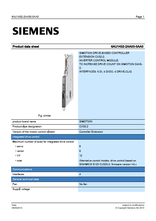
SIMOTION CX32-2 驱动基础控制器扩展模块数据表说明书
• rated value • for signal "1" • for signal "0" Electrical isolation • note Current consumption for "1" signal level, typ. Input delay time for • signal "0" → "1", typ. • signal "1" → "0", typ. Digital inputs/outputs Number of digital inputs/outputs Parameterization possibility of the digital I/Os If used as an input
100 Hz 2 Hz 11 Hz Yes
unlimited buffer duration
cULus
subject to modifications © Copyright Siemens AG 2014
6AU1432-2AA00-0AA0
• Canada
cULus
• Australia
C-Tick
• servo • vector • V/f • note
Communications Interfaces General technical data Fan Supply voltage
SIMOTION CX32-2 Controller Extension
Maestro E220系列产品快速使用指南说明书

E220 Series Quick Start GuideV3Table of Contents1.0Terms and Conditions (3)2.0E220 Series: (4)3.0Setup: (5)3.1Prerequisite (5)3.2Available Accessories (6)4.0Maestro Router Overview (7)4.1LAN Panel Details (7)4.2WAN Panel Details (9)4.3Front Panel Details (10)5.0Connecting Maestro Router (11)6.0Software Configuration (14)7.0Conformity (17)7.1Federal Communications Commission (FCC) Compliance Statement 17 7.2 FCC RF Exposure statement (17)7.3 ISED Notice (17)7.4 ISED RF Exposure Information (18)8.0Appendix: 08.1Pin Power Cable Schematic 08.2Power over Ethernet (1)8.3RS485 wiring diagram (2)8.4Certified antenna (3)8.5Selection of antenna (3)E220 Series| QUICK START GUIDE 1.0 Terms and Conditions1.1.1 This manual is written without warranty.1.1.2 Maestro Wireless Solutions Ltd. reserves the right to modify or improve the product andits accessories, which can also be withdrawn without prior notice.1.1.3 The company stresses the fact that the performance of the product and its accessoriesdepend on the proper use conditions as well as the surrounding environment.1.1.4 Maestro Wireless Solutions Ltd. assumes no liability for damage incurred directly orindirectly from errors, omissions or discrepancies between the router and this manual.1.1.5 Every effort is made to keep the product and its software up to date and running smoothly.However, Maestro Wireless Solutions Ltd. takes no responsibility for, and will not be liable forthe product or its software being temporarily unavailable due to technical issues beyond ourcontrol.1.1.6 The above terms and conditions are subject to change without prior notice. The presentuse of this product implies that the user approves and understands all the above terms andconditions.E220 Series| QUICK START GUIDE E220 Series| QUICK START GUIDE 2.0 E220 Series:Table 1: E220 Series compatible modelsProduct nameTerritories / Operators Bands Fall-back mode Bands Cellular Type E224 EMEA3/8/20 2G 3/8 LTE cat. 1 E224 AT&T, T-Mobile 2/4/12 None N/A LTE cat. 1 E225 Lite EMEA. Asia 1/8 2G 3/8 3G [1] E225 Lite World 1/2/5/6/8/19 2G 2/3/5/8 3G [1] E225 EMEA, Asia 1/8 2G 3/8 3G [1] E225 Worldwide 1/2/5/6/8/19 2G 2/3/5/8 3G [1] E228 Verizon Wireless 4/13 None N/A LTE cat. 4 E228 AT&T, Rogers 2/4/5/13/17 3G [2] 2/5 LTE cat. 4 E228 Telstra, Spark 3/7/28 None N/A LTE cat. 4 E228 NTT Docomo1/19/21 None N/A LTE cat. 4 E228Korea, Thailand, Brazil, etc.1/3/5/7NoneN/ALTE cat. 4[1] 7.2Mbps downlink; 5.76Mbps uplink; [2] 43.2Mbps downlink; 5.76Mbps uplinkFigure 1: E220 Series: High-speed 3G or LTE router3.0 Setup:3.1 Prerequisite3.1.1 Before installing your E220 Series router, verify you have the following:∙Router Hardware with:o Active sim cardo Ethernet cableo Wi-Fi and cellular antennas∙Computer equipped with:o Windows, Mac or Linux operating system.o Ethernet port or Wi-Fi connectivity and Internet serviceo Web browser such as Internet Explorer 8+ or Google Chrome, Mozilla Firefox or Safari to access the Maestro Web Admin Consoleo DHCP set to enable.3.1.2 To enable DHCP, do the following:∙From the Start menu, select Control Panel > Network and Sharing Center and then select the existing connection.∙The Network Connection Status dialog box appears. Click Properties > double click Internet Protocol Version 4 (TCP/IPv4).∙The Internet Protocol Version 4 (TCP/IPv4) Properties dialog box appears. Under the tab General, select Obtain an IP address automatically and Obtain DNSserver address automatically.E220 Series| QUICK START GUIDE 3.2 Available AccessoriesTable 2: The following accessories are available for purchase:Item DescriptionPower Supply / CableACC-CA30 2-pin Micro-Fit 3.0 (M) to stripped wire with 2.5 A fused, 1-metre long cable ACC-PS20 2-pin Molex 1.2A power adapter with Euro plug 2-pin - EuropeACC-PS21 2-pin Molex 1.2A power adapter with NEMA 2-pin plug - AmericaACC-PS22 2-pin Molex 1.2A power adapter with AS3112 3-pin plug – Australia / NZ ACC-PS23 2-pin Molex 1.2A power adapter with BS1363 3-pin plug - UKWi-Fi AntennaACC-A21 5-band 2.4 / 5.8GHz dipole antenna, hinged RP-SMA (M)Cellular / GPS AntennaACC-A11 or ACC-A17A 5-band 850 / 900 / 1800 / 1900 / 2100MHz magnetic mount antenna, 3-meter cable, SMA (M)ACC-A03 GPS 1575.42MHz Magnetic mount antenna, 3-meter cable, SMA (M)ACC-A22 Ultra-wide-band 698-960 / 1575.42 / 1710-2700MHz L-shaped antenna, hinged, SMA (M)MiscellaneousACC-DIN Metal DIN Rail clipACC-CA29 RJ45(M) to RJ45(M)-cable length=1000mm3.2.1 For a full list of Maestro Wireless accessories, refer to: http://www.maestro-/accessories/E220 Series| QUICK START GUIDE 4.0 Maestro Router Overview4.1 LAN Panel DetailsFigure 2: Maestro Router LAN Panel∙Orange - Reset Button: When pushed for 3 seconds the device will reset to default settings.∙Green - DC Power Supply: 2-pin Micro-fit 3.0 connector. Black (left) negative red (right) positive.∙Blue - Ethernet port (LAN): Ethernet cable connects to LAN∙Red - RS-485 & Digital input/output ports (see figure 3 next page):E220 Series| QUICK START GUIDE Figure 3: Maestro Router LAN Panel I/O connector Array∙Red - Top slots are release pins for bottom ports.∙Blue - RS-485o Full-duplex:▪B: Rx –▪A: Rx +▪G: Common Ground▪Y: Tx +▪Z: Tx –o Half-duplex▪A&Y: DATA +▪B&Z: DATA –▪G: Common Ground∙Green - DIO Ports configurable as input or output, 20 AWG (recommended).o Input detection: 5V, max. 48Vo Output: Open collector, max. current 200mA∙Yellow - Ground for both DIOsE220 Series| QUICK START GUIDE 4.2 WAN Panel DetailsFigure 4: Maestro Router WAN Panel Array∙Blue - Ethernet port: Can switch from WAN to LANSupports PoE (Power over Ethernet): PoE wired Ethernet LANs allow the electrical current necessary for the operation to be carried by the data cable rather than carried bypower cords thus removing the needs for an external power supply.∙Green – Mini SIM slot (2FF)∙Orange – GPS / Diversity SMA Antenna Connector: Female (GPS only on LTE version)∙Yellow - Cellular SMA Antenna Connector: FemaleE220 Series| QUICK START GUIDE E220 Series| QUICK START GUIDE 4.3 Front Panel DetailsFigure 5: Front Panel4.3.1 The top panel of Maestro’s E220 Series features 6 LEDs on the front to indicate criticalsystem information. Table 3: LED States and Description NameColor and State DescriptionWI-FIOFFWi-Fi network is inactive Blue Flashing Wi-Fi network connection traffic Blue ONWi-Fi network is up and activate ActivityOFF Cellular data service is not connected Amber ON Cellular data service is connectedNetworkOFFDevice is not registered on a cellular network Amber Flashing Registered on roaming cellular network Amber ON Registered on home cellular network SignalOFFNo signal (CSQ=0 to 5, 97, 98, 99) Amber ON Strong signal (CSQ > 12) Amber FlashingWeak signal (CSQ > 6 to 12) PowerOFF Power off Green ON Power onAlertOFFNo alert, device is running smoothly Red Flashing Software fault (crash, issues)Red ONHardware fault (high temperature, problem with module or SIM card)5.0 Connecting Maestro Router5.1.1 Insert the SIM card in the router as shown below.Figure 6: Inserting the SIM card in the Maestro router Array5.1.2 Connect the antenna to the main connector of the E220.IMPORTANT:Verify the antenna is tightly secured.5.1.3 Connect the Diversity antenna to the Diversity connector.E220 Series| QUICK START GUIDE E220 Series| QUICK START GUIDE Figure 7: Connecting the Wi-Fi & cellular antenna on Maestro router:5.1.4 If the Maestro Router package includes dual antenna’; connect the Diversity Antenna tothe Diversity Connector.NOTE: Dual antenna provides RF diversification, which allows for improved signalstrength and thus better performance for both Wi-Fi and cellular,Certain circumstances and environments may require the use of specific type of antenna or one mounted in a different location. In such case, Maestro has many antenna options to choose from, please contact Maestro Support at ****************************.Table 4: E220 series models and auxiliary antennas:MainModel Auxiliary CommentCellular onlyE225 Lite N/AE224 LiteCellular only Please ensure that the antenna used is suitable for the cellular frequencies in use, for both main and auxiliary connectors E225 GPS onlyE224 E2282-mode GPS and cellular Please ensure that the antenna used is suitable for the cellular frequencies in use, for both main and auxiliary connectorsE220 Series| QUICK START GUIDE 5.1.5 Connect the router LAN port with the computer LAN port.Figure 8: Connecting the router and computer LAN port5.1.6 Connect the AC power to the DC in connector, then connect the Micro-Fit connector tothe power input, located on the LAN-side panel of the Maestro Router.∙ Plug the AC cord into a standard AC receptacle as shown below. ∙The power LED will light when power is applied.Figure 9: Connecting the AC power connector5.1.7 An alternate option is to power the Maestro Router over Ethernet port as the WAN portsupports PoE (Power over Ethernet).NOTE: Please refer to the section Power over Ethernet on Appendix 1 for connections example.E220 Series| QUICK START GUIDE 6.0 Software Configuration6.1.1 On the computer, open a Web browser and then enter the Maestro routers LAN IPaddress. A login dialog window displays.NOTE: Username and Password are case sensitive.Figure 10: Login Dialog BoxTable 5: Web Admin Page Parameters Details IP Address (LAN)192.168.1.1 Username admin PasswordadminTable 6: Wi-Fi enabled, with WPA/WPA2 TKIP keyParameter Details SSIDMaestro WPA KeyW1rele$$6.1.2Click Next on the Quick Start Network Configuration Page (figure 11).6.1.2.1 Configure the network parameters for LAN , WAN , Cellular and Wi-Fi .6.1.2.2 Alternately, go to Management Settings , import and load predefined settings file. 6.1.2.3 Click Save & Apply to set the configuration.NOTE: Default WAN, LAN and cellular connection settings:6.1.2.4 WAN connection – Automatic (DHCP – Automatic IP address lookup). 6.1.2.5 Active DHCP with starting IP address: 192.168.1.100 with poll off 100 clients. 6.1.2.6 WAN as automatic IP, with Cellular backup.6.1.2.7 Cellular default APN is “internet”Figure 11: Quick Start Network Configuration PageE220 Series| QUICK START GUIDE Table 7: Quick Start Network Configuration PageScreen Element Description Local NetworkIPv4-Address Enter the IPv4 Address of LAN interface. The default IPv4 Address is 192.168.1.1IPv4-Netmask Enter the IPv4 Subnet Mask of LAN interface. The default Netmask is 255.255.255.0IPv4-Gateway Enter the Gateway IPv4 of the Gateway. WANProtocol Select the WAN protocol from the available options: ∙Manual∙Automatic∙PPPoEThe default WAN protocol is selected as Automatic.CellularAPN Enter the APN provided by the cellular network operator.Access Point Name (APN) is the name (Web address) of an access point for LTE data connection. Generally, wireless cellular network operator provides the APN to their end users.PIN Enter the PIN of the SIM card.SIM card Personal Identification Number (PIN) is used to lock the card, preventing unauthorized phone calls or access to cellular data.Username Enter the login name. Password Enter the password. Wi-FiEnable By default, Wi-Fi interface is enabled every time the Maestro Router reboots. Click and disable the Wi-Fi interface if you do not want to use them.SSID Service Set Identifier (SSID) is a sequence of characters, which uniquely names a wireless local area network (WLAN).The default SSID is Maestro.Password The default password is W1rele$$.E220 Series| QUICK START GUIDE 7.0 Conformity7.1 Federal Communications Commission (FCC) Compliance Statement7.1.1 This device complies with part 15 of the FCC Rules. Operation is subject to the followingtwo conditions:∙This device may not cause harmful interference.∙This device must accept any interference received, including interference that may cause undesired operation.7.1.2 This device has been tested and found to comply with the limits for a Class B digitalpursuant to Part 15 of the FCC Rules. These limits are designed to provide reasonableprotection against harmful interference in a residential installation. This equipment generates,uses and can radiate radio frequency energy.7.1.2.1 It not installed and used in accordance with the instructions, may cause harmfulinterference to radio communications. here is no guarantee that interference will notoccur in a particular installation.7.1.2.2 If this equipment does cause harmful interference to radio or television reception,which can be determined by turning the equipment off and on, the user isencouraged to try to correct the interference by one or more of the followingmeasures:∙Reorient or relocate the receiving antenna.∙Increase the separation between the equipment and receiver.∙Connect the equipment into an outlet on a circuit different from that to which thereceiver is connected.∙Consult the dealer or an experienced radio/TV technician for help.7.1.3 FCC Caution:7.1.3.1 Changes or modifications not expressly approved by the party responsible forcompliance could void the user’s authority to operate the equipment.7.2 FCC RF Exposure statementThis device complies with FCC radiation exposure limits set forth for an uncontrolled environment.In order to avoid the possibility of exceeding the FCC radio frequency exposure limits, human proximity to the antenna shall not be less than 20cm (8 inches) during normal operation.7.3 ISED NoticeThis device complies with Innovation, Science and Economic Development Canada license-exempt RSS standard(s). Operation is subject to the following two conditions:(1) this device may not cause interference, and(2) this device must accept any interference, including interference that may cause undesiredoperation of the device.E220 Series| QUICK START GUIDE Le présent appareil est conforme aux CNR Innovation, Sciences et Développement économique Canada applicables aux appareils radio exempts de licence. L'exploitation est autorisée aux deux conditions suivantes :(1) l'appareil ne doit pas produire de brouillage, et(2) l'utilisateur de l'appareil doit accepter tout brouillage radioélectrique subi, même si lebrouillage est susceptible d'enThis Class B digital apparatus complies with Canadian ICES-003.Cet appareil numérique de la classe B est conforme à la norme NMB-003 du Canada.IC: 20055-E228F7, 20055-E224LITEF2, 20055-E224LITEF4, 20055-E225LITEF3, 20055-E225F3, 20055-E228F2, 20055-E228F57.4 ISED RF Exposure InformationThis device complies with ISED radiation exposure limits set forth for an uncontrolled environment. In order to avoid the possibility of exceeding the ISED radio frequency exposure limits, human proximity to the antenna shall not be less than 20cm (8 inches) during normal operation.Cet appareil est conforme aux limites d'exposition aux rayonnements de la ISED CNR-102 définies pour un environnement non contrôlé. Afin d'éviter la possibilité de dépasser les limites d'exposition aux fréquences radio de la ISED CNR-102, la proximité humaine à l'antenne ne doit pas être inférieure à 20 cm (8 pouces) pendant le fonctionnement normal.E220 Series| QUICK START GUIDE 8.0 Appendix:8.1 Pin Power Cable SchematicFigure 12:8.2 Power over EthernetFigure 13: PoE_____________________________________________________________________________________8.3 RS485 wiring diagramFigure 14: Half Duplex (Left) RS485 Full Duplex (Right)8.4 Certified antennaDipole Wi-Fi antenna:∙ 5 dBi high performance antenna∙RP-SMA(M) hinged antenna∙RoHS compliant∙Peakgain:*************~2.5GHzWWAN antenna:∙Dipole 4G swivel blade antenna∙Performance across the LTE frequency bands∙698-960 / 1710-2170 / 2500-2700 MHz∙Up to 2 dBi gain∙SMA connector∙RoHS compliant product8.5 Selection of antennaSelection of Wi-Fi antenna:∙Dipole,PeakGain<*************~2.5GHzSelection of antenna type:∙Using the same dipole antenna type as certified module & Modem for FCC as above or external antenna with length > 20 cm.。
Alteon维护手册_version2

Alteon应用交换设备快速安装维护手册V1.0北京凯文斯科技发展有限公司2010-4文档控制修改记录审阅姓名职位 屈宪法技术经理分发拷贝No.姓名 单位 部门 2010-04-15李娜 北京凯文斯科技发展有限公司 技术中心服务部策 划 北京凯文斯技术支持中心编 著 quxianfa技术审核 quxianfa* * * *Beijing KVS Science & Tech Development Co. LtdRoom 2206-2208,22nd/ F YinKe Mansion,No.38,HaiDian Street,HaiDian district,Beijing,China 100080 P.R.C.网址:邮编:100080日期 作者版本 修改记录 2010-04-15 屈宪法;张卫涛;周才云;陈杰V1.0目录第一章前言 (5).使用说明: (5).使用对象: (5).相关说明 (5)1.1A LTEON应用交换机配置概述 (5)1.2A LTEON应用交换机管理配置的基本信息 (6)1.2.1管理端口方式登陆 (6)1.2.2Console口方式登陆 (6)1.2.3 Telnet方式登陆 (7)1.2.4 HTTP方式登陆 (7)1.2.5 HTTPS 方式登陆 (7)1.2.6 EMS软件方式登陆 (8)1.2.7 Alteon应用交换机缺省登录帐号 (9)1.3A LTEON应用交换机的常用功能 (9)第二章软件操作(APPLICATION SWITCH 2000/3000平台) (9)2.1.软件文件简介 (10)2.2升级前的准备工作 (10)2.3软件升级方法 (11)2.4 主菜单操作及详细信息 (13)第三章ALTEON 3000 架构 (27)3.1.A LTEON 3408外观结构 (27)3.1.3设备外观LED指示正面背面面板图: (28)3.2.A LTEON四层应用交换机物理状态检测 (28)3.3.硬件组件故障检查 (29)3.3.1.检查前面板的LED 指示灯显示状况 (29)3.3.2.检查接口指示灯显示状况 (29)4.备组件更换 (29)5.A LTEON交换机基本配置 (29)6.A LTEON交换机在实际部署中的配置 (34)第六章ALTEON的高级特性 (40)6.1VMA(V IRTUAL M ATRIX A RCHITECTURE)参数介绍 (42)6.2DAM模式(D IRECT A CCESS M ODE)参数介绍 (42)6.3D IRECT S ERVER R ETURN(S UBMAC 参数介绍) (42)6.4G RACE参数介绍 (43)6.5A LTEON的负载均衡方式 (44)6.6A LTEON的健康检查方式 (46)6.7A LTEON VRRP的部署方式 (47)第七章 ALTEON应用交换机的维护命令 (48)7.1登录A LTEON应用交换机的方式 (48)7.2查看设备相关日志和工作状态 (49)7.2.1初始信息查看 (49)7.2.2查看软件版本:/boot/cur (49)7.2.3查看配置信息:/cfg/dump (50)7.2.4查看注册信息:/info/swkey (50)7.2.5查看性能:/info/sys/capacity (51)7.2.6查看日志信息:/info/sys/slog (51)7.2.7清除日志信息:/oper/clrlog (51)7.2.8查看业务CPU信息:/stat/sp <SP number>/cpu (52)7.2.9查看会话数:/stat/slb/maint (53)7.3检查设备CPU的占有率 (62)7.3.1 原因分析 (62)7.3.2采取的措施 (62)7.4检查内存占有率 (62)7.4.1 原因分析 (62)7.4.2 采取的措施 (63)7.5双机异常 (63)7.5.1原因分析 (63)7.5.2采取的措施 (63)7.6故障处理工具 (63)7.6.1 Debug (63)第一章前言·使用说明:1、手册更多的从实际使用的角度编写制成,如果涉及到一些理论概念知识表达不够透彻、清晰;请使用者参考相应型号的产品手册。
Osprey ATMOS AURA AG LT系列 S22 用户手册说明书

用户手册ATMOS | AURA AG LT 系列欢迎光临Osprey 。
我们专为您的探险之旅打造最具实用性、耐久性和创新性的携带产品,并以此为豪。
请参阅本用户手册,了解产品功能、使用、保养、客户服务和保修方面的信息。
ATMOS AG LT 50ATMOS AG LT 65AURA AG LT 50AURA AG LT 65• bluesign ® 认证主体面料• GRS-认证再生主体材料• 不含PFC/PFAS 的DWR 涂层23主体面料 bluesign ® 认证再生210D 尼龙蜂窝纹理,不含PFC/PFAS 的DWR 涂层装饰 b luesign ® 认证再生210D 高强力尼龙,不含PFC/PFAS 的DWR 涂层底部 b luesign ® 认证再生500D 高强力 尼龙,不含PFC/PFAS 的DWR 涂层通用1 内含防水罩 a采用不含PFC/PFAS 的DWR 涂层和bluesign ®认证材料2 两侧面板均设有弧形拉链开口3 活动顶盖,配多个绑扎点4 前部shove-it 快速取放口袋,采用强化面料5 侧面双开式大水壶袋6 上/下侧双压缩带7 双拉链式腰带口袋8 双重冰镐挂环,上侧压缩带挂钩9 可移除式睡垫固定带10内部储水仓,后部中央出水口产品承诺化繁为简的Atmos | Aura AG LT ,以流线型的轮廓为技术型背包客提供贴合身体的AntiGravity 悬挂系统。
这款背包比原有同类产品更轻,同时集合了多项简单贴心的功能。
AntiGravity 悬挂系统——连续的轻质网眼背板——将舒适性作为头等重要的体验。
ATMOS AG LT 65男款规格 S/M L/XL 立方英寸 3967 4150 升 65 68磅 4.07 4.25公斤 1.85 1.93 英寸33 h x 15 w x 13 d 35 h x 15 w x 13 d 厘米83 h x 39 w x 32 d 90 h x 39 w x 32 d 负载范围30-40磅 | 14-18公斤30-40磅 | 14-18公斤包含防雨罩防雨罩附加配件3L储水器3L储水器ATMOS AG LT 50男款规格 S/M L/XL 立方英寸 3051 3234 升 50 53磅 4 4.18公斤 1.82 1.9英寸33 h x 14 w x 12 d 35 h x 14 w x 12 d 厘米83 h x 35 w x 30 d 88 h x 35 w x 30 d 负载范围25-35磅| 11-15公斤25-35磅| 11-15公斤包含防雨罩防雨罩附加配件 3L储水器3L储水器AURA AG LT 65女款规格 WXS/S WM/L 立方英寸 3845 3967 升 63 65磅 3.84 4.01公斤 1.74 1.82 英寸31 h x 16 w x 12 d 33 h x 16 w x 12 d 厘米78 h x 40 w x 32 d 83 h x 40 w x 32 d 负载范围 30-40磅 | 14-18公斤30-40磅 | 14-18公斤包含防雨罩防雨罩附加配件 3L储水器3L储水器AURA AG LT 50女款规格 WXS/S WM/L立方英寸 2929 3051 升 48 50磅 3.79 3.97公斤 1.72 1.8英寸30 h x 14 w x 12 d 32 h x 14 w x 12 d 厘米75h x 35w x 30d 80 h x 35 w x 30 d 负载范围 25-35磅| 11-15公斤25-35磅| 11-15公斤包含防雨罩防雨罩附加配件 3L储水器3L储水器背负系统ANTI-GRAVITY 悬挂系统+4 mm 粉末涂层沿周框架ANTI-GRAVITY 背板+ 注塑成型的梯形主干调整系统,易于取物和操作+ 双色三明治网布增加强度+腰部区域带有防滑硅胶印,有利于传递负荷并增加舒适性ANTI-GRAVITY 背带+下侧采用冲切泡沫材料,上侧采用网眼ExoForm 包覆ANTI-GRAVITY 腰带+ 革命性AG 系统将拉紧的背板无缝延伸至腰带+ 腰带覆盖层与框架融为一体,确保一致性负载转移+ 可延展的量身调适Fit-on-the-Fly 腰带,精确贴合不同腰围+ 渐进式长度和角度调节,通过微调实现贴合+斜挎式ErgoPull 设计,拉紧腰带后即可让腰部承重负载调节带胸带LIGHTWIRE 框架ERGOPULL 腰带梯扣背带实现主干调节量身调适FIT-ON-THE-FLY ®腰带主干长度调节指引尺寸/贴合度ATMOS AG LT - 男款尺寸S/M 17-20.5英寸 / 43-52厘米L/XL19.5-23英寸 / 49-58.9厘米AURA AG - 女款尺寸WXS/S 13.5-17英寸 / 34-43厘米WM/L 16-19.5英寸 / 40.5-49厘米如何测量背包的背部尺寸女款专有设计+ 肩部、背板、腰椎和腰带部位独特的悬挂式网眼布可贴合各种体型和尺寸,带来舒适的背负体验。
Solaris TM 9 12 03 平台指南部件号:817-3982-10说明书

Solaris TM 9 12/03 Sun TM硬件平台指南Sun Microsystems, Inc.4150 Network CircleSanta Clara, CA 95054 U.S.A.650-960-1300部件号:817-3982-102003 年 12 月,修订版 A请将有关本文档的意见或建议发送至:/hwdocs/feedbackCopyright 2003 Sun Microsystems, Inc., 4150 Network Circle, Santa Clara, California 95054 U.S.A. 版权所有。
Sun Microsystems, Inc. 对此文档中所述的相关技术拥有知识产权。
在特殊且不受限制的情况下,这些知识产权可能包括/patents上列出的一个或多个美国专利,以及美国和其它国家的一个或多个其它专利或待决的专利申请。
此文档及其所属产品按照限制其使用、复制、分发和反编译的许可证进行分发。
未经 Sun 及其许可证颁发机构的书面授权,不得以任何方式、任何形式复制本产品或本文档的任何部分。
第三方软件,包括字体技术,由 Sun 供应商提供许可和版权。
本产品的某些部分从 Berkeley BSD 系统派生而来,经 University of California 许可授权。
UNIX 是在美国和其它国家注册的商标,经 X/Open Company, Ltd. 独家许可授权。
Sun、Sun Microsystems、Sun 徽标、Answerbook2、、Netra、SunVTS、Sun HSI/P、SunForum、Sun ATM、Java 3D、Sun StorEdge、Sun Blade、Sun Fire、Sun Enterprise、Sun Enterprise Ultra、Power Management、OpenBoot、JumpStart、Ultra、SunPCI、SunSwift、SunFast Ethernet、Sun Quad FastEthernet 、 V oyager和Solaris 是 Sun Microsystems, Inc. 在美国和其它国家的商标、注册商标或服务标记。
- 1、下载文档前请自行甄别文档内容的完整性,平台不提供额外的编辑、内容补充、找答案等附加服务。
- 2、"仅部分预览"的文档,不可在线预览部分如存在完整性等问题,可反馈申请退款(可完整预览的文档不适用该条件!)。
- 3、如文档侵犯您的权益,请联系客服反馈,我们会尽快为您处理(人工客服工作时间:9:00-18:30)。
4655 Great America ParkwaySanta Clara, CA 95054Phone 1-800-4NortelAlteon OS 22.0.2Release Notespart number: 315397-J, January 2005Alteon OS 22.0.2 Release Notes2315397-J, January 2005Copyright 2005 Nortel Networks, Inc.,4655 Great America Parkway, Santa Clara, California 95054, USA. All rights reserved. Part Number: 315397-J.This document is protected by copyright and distributed under licenses restricting its use, copying,distribution, and decompilation. No part of this document may be reproduced in any form by any means without prior written authorization of Nortel Networks, Inc. Documentation is provided “as is” without warranty of any kind, either express or implied, including any kind of implied or express warranty of non-infringement or the implied warranties of merchantability or fitness for a particular purpose.U.S. Government End Users: This document is provided with a “commercial item” as defined by FAR2.101 (Oct 1995) and contains “commercial technical data” and “commercial software documentation” as those terms are used in FAR 12.211-12.212 (Oct 1995). Government End Users are authorized to use this documentation only in accordance with those rights and restrictions set forth herein, consistent with FAR 12.211- 12.212 (Oct 1995), DFARS 227.7202 (JUN 1995) and DFARS 252.227-7015 (Nov 1995).Nortel Networks, Inc. reserves the right to change any products described herein at any time, and without notice. Nortel Networks, Inc. assumes no responsibility or liability arising from the use of productsdescribed herein, except as expressly agreed to in writing by Nortel Networks, Inc. The use and purchase of this product does not convey a license under any patent rights, trademark rights, or any other intellectual property rights of Nortel Networks, Inc.Alteon OS , Alteon 2424, Alteon 2424-SSL, Alteon 2224, 2216, 2208, 3408, Alteon 180, Alteon 180e, Alteon 184, Alteon AD3, Alteon AD4, and ACEswitch are trademarks of Nortel Networks, Inc. in the United States and certain other countries. Cisco ® and EtherChannel ® are registered trademarks of Cisco Systems, Inc. in the United States and certain other countries. Check Point ® and FireWall-1® aretrademarks or registered trademarks of Check Point Software Technologies Ltd. Any other trademarks appearing in this manual are owned by their respective companies.Originated in the U.S.A.Release NotesThese Alteon OS 22.0.2 Release Notes provide the latest information on the softwareand documentation for this release.This document is a supplement to the complete documentation suite. Please keepthis document with your product manuals. For additional technical questions regarding theproduct architecture and features, refer to the product documentation.N OTE – Alteon OS 22.0.2 is a Release to Manufacturing (RTM) software release.This software version will include fixes for existing software limitations as well asnew features and enhancements to the existing software base.Related DocumentationAlteon OS 22.0.2 Command Reference (Part Number 315393-J)Alteon OS 22.0.2 Application Guide (Part Number 315394-J)Alteon Application Switch Hardware Installation Guide (Part Number 315396-E)Alteon OS BBI Quick Guide (Part Number 315395-C rev 01)Alteon OS 22.0.1 Release Notes (Part Number 315397-H)Hardware SupportThe Alteon Application Switch is the next generation, high performance, Layer 2-7,fixed network switch. This application switch has increases in switching performance, sessioncapacity, feature capacity, and port density from the Alteon 180 series and AD series Webswitches.3 315397-J, January 2005Alteon OS 22.0.2 Release Notes4315397-J, January 2005Alteon Application Switch 2000 and 3000 Series Alteon OS 22.0.2 is supported on the following Alteon Application Switch platforms: Alteon 2208: supports 8 Fast Ethernet ports and 2 Small Form-Factor Pluggable (SFP)GBIC Ethernet ports. Alteon 2216: supports 16 Fast Ethernet ports and 2 SFP GBIC Ethernet ports. Alteon 2224: supports 24 Fast Ethernet ports and 2 SFP GBIC Ethernet ports. Alteon 2424: supports 24 Fast Ethernet ports and 4 SFP GBIC Ethernet ports. Alteon 2424-SSL: supports 24 Fast Ethernet ports and 4 SFP GBIC Ethernet ports, and an on-board SSL processor that allows SSL acceleration and SSL VPN functionality. Alteon 3408: supports 4 1000 Mbps SFP GBICS, 4 10/100/1000Base-T Copper Autoselecting and Autosensing RJ45 connectors, 4 dual-mode 1000 Mbps SFP GBIC or 10/100/1000Base-T copper ports. Either type of port can be set as a “preferred” or “backup” connection.Alteon Application Switch Model 2208 and 2216Supported Software Future hardware revisions of the Alteon Application Switch Model 2208 and 2216 will require that customers use Alteon OS versions 21.0.7 or higher or 22.0.2 or higher. In these future hardware revisions, any earlier software images will not load or function properly.On these versions of the Alteon Application 2208 and 2216 Switches, the software will block a software downgrade to an unsupported release through TFTP download and display the following error message:If the error message noted above is displayed during a downgrade procedure, only the software versions described in the error message can be used as base line.The switch is unable to prevent a downgrade operation through a serial download. If an unsupported software version is applied to the switch through a serial download, the switch will not boot properly which will result in a switch malfunction.Error: Software version of the downloaded image is NOT supported on this version of the hardware. Please download the supported software version (21.0.7.0 or later, or 22.0.2.0 or later) instead.Alteon OS 22.0.2 Release Notes5315397-J, January 2005If release 21 of Alteon OS is the desired software version, ensure that release 21.0.7 or later is used. This release is available via download from the Nortel Networks customer support web site. If you do not have access to this web site, contact Nortel Networks by e-mail atAlteon_keys@ to obtain the software on a one time basis.To determine if a Model 2208 or 2216 Alteon Application Switch only supports Alteon OS 21.0.7 or later or 22.0.2 or later, check the hardware revision information located on the rear of the chassis and consult any additional documentation that was included with the switch.This revision number can also be obtained through the CLI through the command /info/sys/gen and checking the revision number as illustrated below:The hardware revision number can also be determined via the Alteon OSBrowser-Based Interface where the revision number is displayed as the value Chassis Rev or in Alteon EMS 3.1.1 or later where it is displayed as the value Chassis Revision Number .System Information at 14:33:45 Thu Nov 11, 2004Alteon Application Switch 2208Switch is up 0 days, 0 hours, 0 minutes and 0 seconds.Last boot: 17:38:07 Tue Sep 21, 2004 (power cycle)Last apply:Last save: 11:21:05 Fri Nov 5, 2004MAC address: 00:11:58:91:ae:00 IP (If 1) address: 0.0.0.0Hardware Order No: EB1412010 Serial No: SSCPB80007 Rev: 05(Hardware Revision Number in this example is 05)Mainboard Hardware: Part No: P316677-B Rev: 04Management Processor Board Hardware: Part No: P314080-A Rev: 02Fast Ethernet Board Hardware: Part No: P316676-A Rev: 03Software Version 22.0.2.0 (FLASH image1), factorydefault configuration.Alteon OS 22.0.2 Release Notes6315397-J, January 2005Software Base Alteon OS 22.0.2 is based on Alteon OS 22.0 and Alteon OS 22.0.1 functionality that is currently implemented across the Alteon Application Switch models.Images for Alteon 3408 3408 Image file: AAS-22.0.2.0-3000-AlteonOS.img 3408 Binary Image file: AAS-22.0.2.0-3000-Serial.img Images for Alteon 2000 Series 2000 Series Image file: AAS-22.0.2.0-2000-AlteonOS.img 2000 Series Binary Image file: AAS-22.0.2.0-2000-Serial.img Common Files AAS Boot Image file: AAS-22.0.2.0-Boot.img MIB files: AAS-22.0.2.0_mib.zip N OTE – Nortel Networks recommends that customers upgrade their Alteon OS boot image to 22.0.2.Installing Alteon OS 22.0.2The Alteon OS 22.0.2 image size exceeds the download limit of 3MB for image downloads through TFTP present in Alteon OS previous to version 21.0.4. If the switch is being upgraded from a version earlier than 21.0.4 follow the procedure entitled “Upgrading From A Version Prior To 21.0.4”. Otherwise, follow the procedure entitled “Upgrading From A Ver-sion Newer Than 21.0.4” on page 8.Upgrading From A Version Prior To 21.0.4To download Alteon OS 22.0.2, you will first have to perform an intermediary upgrade to Alteon OS 21.0.4.0 (or higher version of 21.0.x) into the image1 slot and then download Alteon OS 22.0.2 into the image2 slot. After this is completed, the switch can be set to reboot from image2 in order to load Alteon OS 22.0.2.Alteon OS 22.0.2 Release Notes7315397-J, January 2005N OTE – As an alternative, you may perform a serial download of the Alteon OS 22.0.2 binary image file directly into the image1 slot. See Appendix C, “Performing a Serial Download”, of the Alteon OS 22.0.2 Command Reference (Part Number 315393-J) for the necessary steps.1.Download Alteon OS 21.0.4 (or a higher version of the 21.0.x software) into the image1slot.Alteon OS 21.0.4 or higher software permits a software image greater than 3MB tobe downloaded into the image2 slot only.2.Select image1 for the next reboot and reset the switch.The switch should now boot with the Alteon OS version downloaded in step 1.3.In the boot options menu, download the new Alteon OS 22.0.2 image into the image2 slot.4.Select image2 for the next reboot and reset the switch.5.Verify that Alteon OS 22.0.2 has been properly installed into image2.>> Main# /boot/gtimg 1Enter hostname or IP address of TFTP server: <IP or server name>Enter name of file on TFTP server: <21.0.4 or later file name><software download begins>. . . . . . .>> Boot Options# image 1>> Boot Options# reset >> Main# /boot/gtimg 2Enter hostname or IP address of TFTP server: <IP or server name>Enter name of file on TFTP server: <image file name><software download begins>. . . . . . .>> Boot Options# image 2Next boot will use switch software image1 instead of image2>> Boot Options# resetAlteon OS 22.0.2 Release Notes8315397-J, January 20056.Upgrade the image1 slot to Alteon OS 22.0.2.7.Select image1 for the next boot and reset the switch.Upgrading From A Version Newer Than 21.0.4If the version of Alteon OS present on the switch is newer than 21.0.4 then follow these instructions for upgrading Alteon OS.1.Download the new Alteon OS 22.0.2 image into the image2 slot.2.Select image2 for the next reboot and reset the switch.3.Verify that Alteon OS 22.0.2 has been properly installed into image2.>> Main# /boot/gtimg 1Enter hostname or IP address of TFTP server: <IP or server name>Enter name of file on TFTP server: <image file name><software download begins>. . . . . . .AUTION —When you mix Alteon OS 22.0.2 (or later) images with images prior to 22.0 in the later than 22.0 use a different flash location for the crash dump.>> Boot Options# image 1>> Boot Options# reset>> Main# /boot/gtimg 2Enter hostname or IP address of TFTP server: <IP or server name>Enter name of file on TFTP server: <image file name><software download begins>. . . . . . .>> Boot Options# image 2Next boot will use switch software image1 instead of image2>> Boot Options# resetAlteon OS 22.0.2 Release Notes9315397-J, January 20054.Upgrade the image1 slot to Alteon OS 22.0.2.5.Select image1 for the next boot and reset the switch.Software SupportObtaining Software Patches and License KeysIf you have purchased one or more of the Alteon Application Switch models 2208 or 2216 and do not have a support contract, you may send a request to Nortel Networks Technical Support to obtain a one-time exception for a patch release of an older version of software. The e-mail address is Alteon_keys@.>> Main# /boot/gtimg 1Enter hostname or IP address of TFTP server: <IP or server name>Enter name of file on TFTP server: <image file name><software download begins>. . . . . . .AUTION —When you mix Alteon OS 22.0.2 (or later) images with images prior to 22.0 in the later than 22.0 use a different flash location for the crash dump.>> Boot Options# image 1>> Boot Options# resetAlteon OS 22.0.2 Release Notes10315397-J, January 2005Version 22.0.2 Software Feature Limitations The following fixes have been implemented since version 22.0.1 of Alteon OS.Priority 1 - Critical Impact BugsThe switch will no longer malfunction after the configuration of a URL contract for a filter is left uncompleted for more than approximately five minutes. (Q01029739)SFAs will no longer cause switch malfunction when new configurations are applied. (Q00857009-01)A memory leak caused by SNMP health checking has been fixed. (Q01025816)The command /cfg/slb/group <group number>/add now works for real servers above 256. (Q01037782)IDS filter groups now work properly with multiple IDS groups configured. (Q01039584)Non-zero mask 0.0.0.0 routes will no longer be lost after reboot. (Q00957422)Issues surrounding Layer 7 server load balancing for keep alive connections have been resolved. (Q00636110-02)The switch will now send scripted health checks when DSR is enabled. (Q01010670)Configuration of IDSLB will no longer cause two or more switches to become VRRP masters in some VRIDs. (Q00981660) The switch will no longer malfunction when more than 72 characters are used in anadvanced health check formula. (Q01022948)Priority 2 - High Impact BugsDynamic NAT sessions will no longer age out prematurely. (Q00983550) In a basic SLB environment that contains at least one real server, a switch malfunctionwill occur if the user configures an invalid real server number in the group advanced health check formula string. Ensure that only valid real server numbers are used to prevent this issue. (Q01022944)Previously, if a back up real server fails a health check it would still show up inrelated statistics. This behavior has been fixed. (Q00953646-01)Wildcard usage in GSLB network domain string comparisons will now behave properly using either the asterisk (*) or question mark (?) as the wildcard character. (Q00972566)A fast age-out will only be performed on a session entry with a Reset packet only if the sequence number of the packet is within the expected range. If the sequence number is not within the expected range, the packet will be dropped. (Q00867956)Issues with RADIUS Accounting while DAM is enabled have been resolved.(Q01007742)GSLB rules can now be applied via Alteon EMS. (Q01016034)SNMP support has been added to Alteon EMS for the “insert cookie dname” feature.(Q00877957)SLB health check synchronization will now work properly. (Q00964704)“Leastconn” load balancing has been reformulated for better load balancing (Q01015254) Instances where a switch would not reboot after a malfunction have been fixed.(Q00977354)Problems with the addition and removal of static routes have been fixed. (Q00980823) VRRP state will no longer stay in Init mode after making Layer 3 configuration changes.(Q00987237)Response times during HTTP content checking should now be more consistent.(Q00991118)Use of the ping command will now work after a port has been moved from one VLAN to another. (Q00996865)Server load balancing sessions will now be cleared properly. (Q01020059)SSH and HTTPS key generation will no longer cause SLB and GSLB connections to dis-connect. (Q00986128)The switch will no longer continue to allow sessions to be opened by a real server after it has reached the maximum connections threshold. (Q01025472)The value for unlimited connections is now consistent between SLB and GSLB.(Q00965746)Changing the ARP timer will no longer cause continuous traffic loss. (Q00977153)Looping apparent in STP Group 1 in some configurations has been fixed. (Q00613888) Layer 3 traffic will now be properly load balanced over all of the links in a trunk group when a gateway is used to route traffic. (Q01044880)Roundrobin loading balancing will now work properly with Layer 7 WCRs. (Q01048006) SSH will no longer cause switch malfunction under certain circumstances. (Q01048566)Priority 3 - Medium Impact BugsPreviously, the use of a stress tool in certain configurations would result in improper counts. This issue has been resolved. (Q00786947)Under certain configurations, the NTP services in previous versions would not operated as expected. This issue has been resolved. (Q00951700)MIB support has been added for individual SP memory usage. (Q00973926)Improper values referenced in CLI help for GSLB commands have been corrected.(Q00966643)Load balancing using THASH and PHASH in tandem had not performed as expected in previous versions. This issue has been corrected. (Q00986749)A client VIP will now respond with the MAC address of the VIP, not the MAC address ofthe interface. (Q00990433)Statistics for filtered, denied frames will no longer increment unless a frame has actually been denied. (Q01021631)An error message will now be provided when the /cfg/ptcfg command is issued and the management port is inoperable. (Q01027174)The CLI help for the /info/slb/idshash command is now correct. (Q01037844) Issues surrounding the improper incrementing of Layer 7 WCR statistics have been fixed (Q00957228)ARP address list duplication has been resolved. (Q00972988)The default GSLB rule (rule 1) will now be displayed when viewed in the Alteon EMS GSLB Rules page. (Q00967955)The switch only sends the first eight characters of a user name when performing a SIP health check regardless of whether the user name is longer than this length. This does not affect the performance of the health check. Using a maximum length of eight characters for a user name ensures that this does not become an issue. (Q00976755)The switch will no longer malfunction when it encounters a malformed IP packet with FTP enabled. (Q00705008-01)The Contract Groups page in Alteon EMS will now work as expected when adding and removing contracts. (Q00968739)Filter statistics for “goto” filters will now increment properly. (Q00998643)The error message displayed when attempting to download an unsupported software version will now correctly describe the situation encountered. (Q01022002)Octet statistics will now display correctly in the CLI command /stats/port/info.(Q01022413)SSL port 29 is now restricted from being added to an IDS group because there is no SSL server on this port. (Q01038457)The switch will now recognize host names that are not preceded by “www” when the host name is specified and host look-up is disabled. (Q00974783)Operationally disabled real servers will now go into slowstart mode only when they become operationally enabled again. (Q00979146-02)A wildcard MAC address can be used in non-IP filtering and applied to a port withIP filtering enabled. Previously, this condition had caused an error. (Q00986805)An incorrect error message in the Configure > Security > UDP Blast > Insert page of Alteon EMS has been fixed to more properly represent the error that is occurring.(Q00781524)Anomalous characters will no longer be displayed when the administrator of a switch attempts to replace the current image. (Q01007689)Quotation marks may now be used in scripted health checks. (Q00919652-01)NAT session time out values will now be displayed correctly in Alteon EMS.(Q01024711)Adjustment for Daylight Savings Time on the switch will now be performed correctly.(Q01011811-01)ICMP health checking for multiple groups that use the same real servers will no longer fail. (Q01029595)The browser-based interface will now display switch ports above port one in the Layer 4 switching area of the dashboard. (Q01037879)Issues with the WCR filter combined with a cookie insert have been resolved.(Q00964537)Instances where the switch malfunction while the management port was being enabled have been corrected. (Q00976242)The switch will no longer malfunction when a real server name contains special characters. (Q00979664)Previously, under certain conditions, a switch malfunction would occur when it received MSTP BPDU packets. This is no longer the case. (Q00981593)The Alteon EMS SLB Summary page will now display real server back-up information correctly. (Q00957215)The diff command will no longer show the SNMP USM password unencrypted after the apply command is executed. (Q01011552)Maintenance statistics missing from the browser-based interface and Alteon EMS have been added. (Q01032267)Fields have been added to the browser-based interface Layer 4 switch ports configuration table to display hot-standby, filtering, IDSLB, inter-switching, and RTS processing state.(Q01037894)The dump command will now successfully complete when issued in the CLI through Telnet. (Q00932097)The LACP key value range is now consistent between Alteon switches running Alteon OS22.0.2 and Passport 8600 products. (Q01011874)When GSLB and noremote is enabled, a 503 error message will no longer be sent back to the client. (Q00978295-01)URL string values are now displayed based on URL case configuration. (Q01023627)Consecutive HTTP GET requests inside of a single HTTP session will no longer cause the display of a 503 error. (Q00966075)The command oper/slb/dis will now function as expected when dealing with VRRP priority. (Q00969673)Standalone GSLB will now work regardless of whether the local VIR is defined.(Q00982279)Gateways in a trunk group will now respond in a more timely manner when ports in the trunk group become disabled. (Q01041809)Priority 4 and 5 - Low Impact BugsThe CN name offered by the switch certificate during HTTPS management is now valid.(Q00981805)An error message has been added to the PIP filter so that when an EPIP on a filter is configured improperly the administrator will be warned. There was no error message for this condition in previous implementations. (Q00986801)Alteon EMS functionality for enabling pattern matching on a filter will now mirror the same functionality in the CLI. (Q01022618)MIBs will now comply with SMI version 2. (Q00975782)The Alteon EMS page Configure > Layer 7 > URL Parsing > HTTP methods (and equivalent CLI command) will now properly display newly inserted HTTP methods whena diff or diff flash command is issued. (Q00985280)Alteon EMS now allows for the addition of a disabled VR to a VIR group. (Q00867778) Filtering using wildcard MAC addresses will now function properly. (Q00986802)Alteon EMS will no longer allow the entry of a Maximum Stored Link-State Advertisement value that is invalid. (Q00940723)String case discrepancies between the /cfg/slb/layer7/slb/cur and /cfg/sl/ vir commands have been fixed. (Q00972207)During an upgrade or downgrade procedure, multi-r-port configuration information will now be completely saved to the flash memory. (Q00973194)Software Features and EnhancementsAs noted previously, Alteon OS 22.0.2 is a RTM software release and as such will contain the following new features and enhancements to the existing software base:Variable depth pattern matching searches using the greater than (>) and less than (<)operators has been added. (Q00978487)Alteon OS now supports 64 bytes of domain name size and 32 bytes of host name size.(Q00976805)64 r-ports are now supported in multi-r-port configurations. (Q00976802)SSLID pbind will now work as specified in RFC 2246. (Q00981675)New MIBs have been added to support individual SP memory usage. (Q00973926)Reverse session updates have been added to the Intelligent Traffic Management.(Q00914770)The depth of Layer 7 packet inspection can now be specified so that the switch administrator has the option to set how many packets will be inspected during this process. (Q01018817)An archive has been added for user limit statistics captured throughBandwidth Management. (Q01018820)A new god mode CLI has been added to display MP CPLD version information.(Q00999576)。