丹麦BK产品介绍_图文.
丹麦BK产品介绍

建筑声学产品·仪器测量
ODEON 建筑声学模拟软件
7835/7836/7837型ODEON 建筑声学模拟软件,是由丹麦技 术大学与BK公司合作研发的强大的声学建模软件位的最佳合作伙 伴.
功能介绍
预测和优化房间声学环境 预测建筑装修对于声学环境的影响 改善已有建筑的声学环境
产品特点
快速建模:通过内置建模工具或导入CAD模型 数字化模型修正 灵活选择声源,材料和接受端 更快的计算速度 多种视觉展示,包括2D和3D图像 高品质音响效果回放,模拟任何位置的声学效果 方便比较多种方案
DIRAC建筑声学测量软件
建筑声学套装范例 (左:2270+无指向性声源+功放,右:2250+地板打击器)
功能介绍
7841型DIRAC建筑声学测量软件, 可以作为2250/2270型手持式分析仪的补充,也可独立工作。
2250和2270是B&K公司最新一代手持式分析仪。可进行噪声 和振动的常规测量,以及建筑声学参数测量工作。2250是单通道分 析仪,可进行混响时间测量和隔声测量(需测量两次),2270是双 通道分析仪,除可进行所有2250的测量外,还可以一次实现隔声测 量(接收室和发声室同步)。所有测量数据可导入PULSE Reflex软 件进行后处理,方便出具各种报告。
建筑声学产品·仪器测量
丹麦
企业介绍
丹麦Brüel & Kjær公司是全世界最大的声学、振动测量分析仪 器的研究及制造公司,已具有六十年的历史和丰富的经验,进入中 国市场已有五十多年。
丹麦Brüel & Kjær 公司是英国思百吉(Spectris)集团旗下的 全资子公司。该集团在中国的子公司----上海思百吉仪器系统有限 公司,直接从事Brüel & Kjær公司的各种业务。
Osbk产品表(零售价)

SH-3519 SH-3530
系列待定
规格:1800×800mm左右 适用位置:电视背景墙、玄关背景墙等 工艺:复合玻璃
3片合一、4片合一、6片合一,纹路对接 品名 冰玉 透光背景 冰玉 透光背景 规格mm 高度(18002100)×800左 右 高度1800以下 ×800左右 厚度mm 17 17 片数/ 包 平方/包 元/平方 5340 4140
绿玉+白 玉+黑金 花
吉祥玉+ 白玉+黑 金花 黄玉+白 玉+黑金 花
600×600
玉魔方
MF-0302
600×600
15
3
1.08
702
玉魔方
MF-0303
600×600
15
3
1.08
702
MF-04
品名 编号 材质 白玉+黄 玉+黑金 花 规格mm 厚度 mm 15 片数/ 包 3 平方/ 包 1.08 元/ 片 810
白玉+黄 玉
黄玉+白 玉 白玉+绿 玉 绿玉+白 玉 吉祥玉+ 白玉
MF-0201 750
MF-0202 500
MF-0203 500
品名 玉魔方 玉魔方
编号 MF-0201 MF-0202
材质 绿玉+黑 金花 吉祥玉+ 黑金花
规格mm 600×600 600×600
厚度 mm 15 15
片数/ 包 3 3
型号
规格mm
厚度mm
片数/包
平方/包
元/ 片
XL-760
600×600
15
3
1.08
756
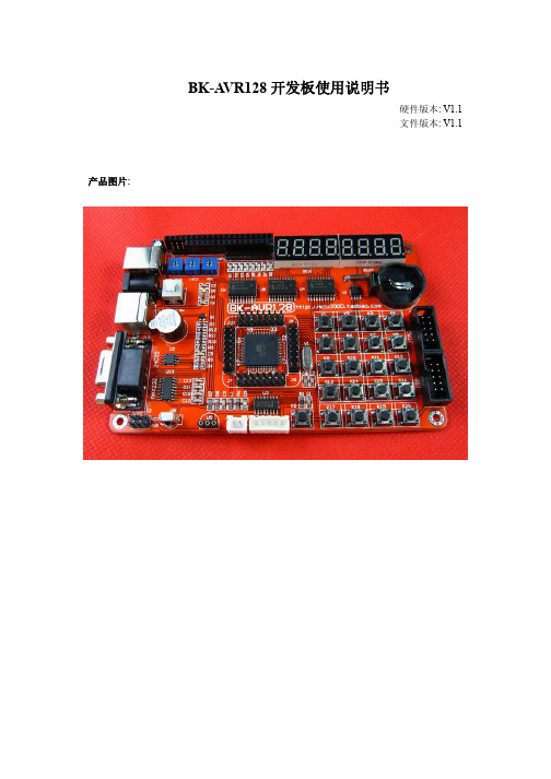
BK-AVR128说明书
图标,按提示直至安装完成.若提
第三章 快速入门
3.1 第一个 ICC AVR 程序 本章假设用户已经安装好所有必需的软件,如 ICCAVR AVRstudio,我们将以一 个 LED 闪 烁 程 序 讲 述 用 ICCAVR 开 发 软 件 编 写 一 个 简 单 的 程 序 , 并 在 BK-AVR128 开发反上进行实验及仿真.
8
点击 change 可改变软件的安装路径,一般按默认即可不用修改。
点击“Next”
9
点击 “Install”然后等待软件安装完成。
点击 “Finish” 软件安装完成。 2.3 ISP 下载器驱动安装
10
将我们提供的 USB 下载器软件及驱动文件解压到你的硬盘上,并将 ISP 下载器 插到计算机的 USB 接口。 如果之前还没安装过 USBASP 下载器驱动,插入 USB 后您的计算机将自动弹出下列提示框, 引导您安装 USB 驱动软件
2) 软件设置及使用 打开 AVRstudio 软件
19
执行菜单栏的”File|Open File”
20
选择.cof 后缀的文件,点击”打开”. 点击”保存”
21
选择芯片型号为 Atmega128,仿真器型号为 JTAG ICE,Port 端口号根据实际情 况设置(最大不能超过 com4),以上都设置好后点击 Finish 进入仿真操作. 端口号的查询方法:在桌面上”我的电脑图标”右击,选择“管理”-----设备管理 器------端口(COM 和 LPT)如下图
数码管(段 E)
数码管(段 F)
数码管(段 G)
数码管(段 dp)
矩阵键盘(行 1) 按键 K17
AT24C02(SCL)
矩阵键盘(行 2) 按键 K18
Parker Hannifin 电子传感器和 Reed 传感器产品介绍说明书
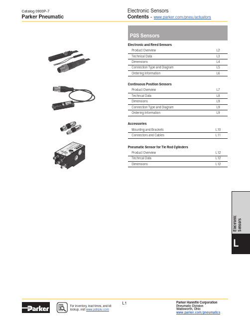
Electronic SensorsContents - /pneu/actuators Catalog 0900P-7Parker PneumaticElectronic and Reed Sensors Product Overview L2Technical Data L3DimensionsL4Connection Type and Diagram L5Ordering Information L6Continuous Position Sensors Product Overview L7Techncal Data L8DimensionsL9Connection Type and Diagram L9Ordering Information L9AccessoriesMounting and Brackets L10Connectors and CablesL11Pneumatic Sensor for Tie Rod Cylinders Product Overview L12Techncal Data L12DimensionsL12Product OverviewThe P8S Series magnetic cylinder sensor enables quick, precise and contactless sensing of the piston’s position in cylinders. It is easy to mount, can be used in numerous applications and offers an outstanding price-performance ratio.Product OverviewAs the term magnetic switch suggests, these are operated by magnetic fields; another description widely used is magnetic “SENSOR”. As our eyes sense change of light, our ears sense the change of sound, magnetic sensors / switches sense the change of magnetic flux in pneumatic and hydraulic cylinders. When magnetic sensors sense a magnetic field it will give a switching signal, through a control circuit, allowing sensing or control operation to be achieved.Because of the characteristics of magnetic sensors they can sense a change of magnetic field relative to the position of the magnet, such as in a pneumatic or hydraulic cylinder, whereby the magnet is attached to a moving piston and thus the position of the moving part (ie Piston) can be detected. The magnet is mounted on the piston of the cylinder and thus moves with the piston.The magnetic sensor (switch) is fixed either directly to the cylinder or with an additional mounting bracket. When the piston (magnet) moves to the position under a magnetic sensor, the switch will operate due to the change of the magnetic field and give a switching signal.Thus the position of the piston can be identified and a resulting signal generated to continue the sequence of a circuit.Magnetic sensors available can be classified into two different groups, they are sensors with contacts which are called mechanically operated or reed sensors and the other type is sensors without contacts and are called solid state type or electronic.Parker P8S Series sensors are suitable for use with a large range of actuators. They can either be inserted directly into the cylinder tube extrusion or mounted using additional brackets. For direct mounting the sensor is positioned within the cylinder sensor groove, offering mechanical protection, then securely clamped into position by a simple turn of a screw. For other cylinder versions there are a number of optional sensors brackets that clamp to the cylinder and offer other mounting positions.For easy installation there are several cable lengths available with either M8 connector or flying lead. The electronic sensors are “Solid State”, i.e. they have no moving parts. They are provided with short-circuit protection and transient protection as standard. The built-in electronics make the sensors suitable for applications with high on and off switching frequency where long service life is required.Please note that for low temperature applications sensors are normally specified for full performance down to -30°C only. High temperature cylinders do not have a magnetic piston and therefore cannot be used with sensors.P8S Electronic and Reed SensorsDimensions, mm (inch)PNP, NPN Output 10 to 30 V DC Reed Output 5 to 230 V AC/DCScrew 1/4 turnConnection Type and DiagramPNP NONPN NO NPN NCReed NO 3-wirePin assignment, M8 with knurled nut bn: brown bk: black bu: blue Q: load M: Mass L+: PowerPNP NCReed NO 2-wireReed NC 2-wire+ -Q NAMUR NO ATEX 1G, 1DPNP NO ATEX 3G, 3DFlying leads4 (out)3 (-)1 (+)bnbubkConnectionsSquare body design, insert straight in T-slot, screw 1/4 turnNote:-30 to +80 °C (PUR cable) I -30 to + 70 °C (PVC cable) I -25 to +80 °C (NAMUR 1GD I -20 to +50 °C (ATEX 3GD) All sensors come with an adapter for S-dovetail Parker type OSP grooves. * with an aluminium adapterOrdering InformationMany applications require more than just end of stroke sensing of an actuator, but traditional methods of continuous sensing are expensive to implement. Parker’s CPS (Continuous Position Sensor) enables quick, precise and contactless continuous position sensing of a magnetic piston.CPS sensors continuously supply data via analog outputs or IO-Link. Analog position sensors have a voltage output of 0 V ... 10 V as well as a current output of 4 mA ... 20 mA. CPS enables flexible machine concepts, making it possible to solve tasks in areas such as quality monitoring and process control in conjunction with pneumatic cylinders. This continuous transfer of position data upgrades the functionality of the pneumatic cylinders by making them more intelligent, and as a result, more versatile. CPS settings can be adjusted during or after installation using a teach button or using IO-Link.CPS can be mounted directly in standard T -slots without the need for additional accessories. Mounting on other cylinder types, (round, tie rod) is possible with adapters.• Continuous position sensing• IO-Link communication with M12 connector • No modification to the actuator • Analog version with M8 connector• 5 sizes with sensing ranges from 32 mm to 256 mm • IP67 design suitable for any industrial application • Yellow teach button for easy set-upTechnical specification:1 ms sampling rate0.03% full scale resolution 0.06% full scale repeatability 0.3 mm Linearity errorHow it works:The CPS product detects the position of an actuator via the magnet on the piston. The sensor settings can easily be adjusted during installation using the yellow teach button or during operation over the IO-Link communication. This upgrades the functionality of the pneumatic actuator by making it more intelligent and versatile in support of the Industry 4.0 initiative.How it connects:Analog version has a M8 connector and a voltage output of 0-10V as well as a current output of 4-20mA. IO-Link version has a M12 connector and transmits position via 2 bytes of process input data and also allows for parameter control of measuring range and locking of the teach button.It can be controlled by Class A or Class B IO-Link Masters.Without Adapter:Direct drop-in T -slotT-slot dimensions [mm ± 0.1]1) Pivot sensor into the slot2) Teach the CPS unit the desired measuring range 3) Tighten set screws5.554.806.803.40How it installs:The Parker CPS requires the use of a magnetic piston. The product will ft T -slot cylinders without any additional mounting hardware.Product OverviewP8S Continuous Position Sensors1) ± 1 mm 2)Reverse-polarity protected, operation in short-circuit protected network: max. 8 A. 3) Without load 4)Power output, at 24 V 5)Voltage output6) FSR: Full Scale Range;max. measuring range. 7)At 25°C, linearity error (maximum deviation)depending on response curve and minimal deviation function. 8)At 25°C, repeatability magnet movement in one direction. 9)Only in standard mode, not in IO-Link mode. 10)The analogue measured value can deviateunder transient conditions.Installation: Drop in, fixed by allen key 1.5 mm Measuring range:32 to 256 mm depending on type 1)Housing length:45 to 269 mm depending on type Output Function: Analog | IO-Link Analog output (voltage):0 to 10 V | -Analog output (current): 4 to 20 mA | -Teach-in:YesEnclosure rating:IP 67 (according to EN 60529)Supply Voltage: 2)15 to 30 V DCPower consumption: 3)<= 22 mA (analog) | <= 25 ma (IO-Link)Max load resistance: 4)<= 500 ΩMin load resistance: 5)<= 2 kΩProtection class:III Time delay before availability: 1.5 sRequired magnetic field sensitivity: 3 mT / 2 mT (analog) | 3 mT (IO-Link)Resolution: 6)0.03% full scale range (max >=0.05 mm)Linearity error: 7) 0.3 mmRepeat accuracy: 8)0.06% full scale range (>= 0.1 mm)Sampling rate: 9)1 msIndication LED color: Yellow (analog)Reserve polarity protection:Yes (analog)Short circuit protection:Yes (analog)Ambient operating temperature range:-20 to +70 °C (PUR cable)Shock and vibration resistance:30 g 11 ms / 10 … 55 Hz, 1 mm EMC: 10)According to EN 60947-5-2International standard:CE | C UL US | CCC (not applicable) | RoHs | IO-Link UL file No:On requestHousing material:Plastic polyamid PA12Screw material: Stainless steel Cable material:PUR (Polyurethane)Conductor cross-section:0.08 mm²Connector:M12 (IO-Link) or M8 (analog)TechnicalDimensions, mm (inch)Connection Type and DiagramPart NumberL1L2 *L3Analog IO-Link 453240P8SAGACHA P8SAGHMHA 776472P8SAGACHB P8SAGHMHB 141128136P8SAGACHD P8SAGHMHD 205192200P8SAGACHF P8SAGHMHF269256264P8SAGACHHP8SAGHMHH*L2 equal to the measuring range.OutputMeasuring Length ConfigurationOptionPart Number Weight [g]For Product SeriesAnalog32 mm Teach ButtonP8SAGACHA 16With T -slot groove *64 mmP8SAGACHB 26128 mm P8SAGACHD 46192 mm P8SAGACHF 66256 mm P8SAGACHH 86IO-Link32 mm Teach Button or IO-Link parameter P8SAGHMHA 20With T -slot groove *64 mmP8SAGHMHB 30128 mm P8SAGHMHD 50192 mm P8SAGHMHF 70256 mmP8SAGHMHH90* Required magnetic field sensitivity: 3mT / -2 mT (Analog) / 3mT (IO-Link) Note:PUR cable with M12 (IO-Link) or M8 (Analog) male connector knurled nut, 4-pin, 0,3 meter length. Please consult for measuring range 96, 160 & 224 mm.Ordering Information, Drop-in T-slotNote:PUR cable with M12 (IO-Link) or M8 (Analog) male connector knurled nut, 4-pin, 0,3 meter length. Please consult for measuring range 96, 160 & 224 mm.IO Link version PUR 0.3 meter length with M12 male connector knurled nut, 4-pin PUR 0.3 meter length with M8 male connector knurled nut, 4-pinbrn wht blk bluAnalog versionbrn blk whtbluDimensions, Ordering InformationFor Products SeriesPart Number Weight [g]Tie rods, 4MA, P1F , P1D, PTR, 2MNR P8S-TMAOX 65Tie rods, P1F-T Ø 32-100P8S-TMA0710Tie rods, P1F-T Ø 125-320P8S-TMA0832T -Slot OSP Ø 108872FIL 3T -Slot 2002 Series Ø 168865FIL 4T -Slot 2002/P120 Series Ø 25-808866FIL 5Round cylinder Ø10-25P8S-TMC0127Round cylinder Ø 32-63P8S-TMC0229Round cylinder Ø 80-125P8S-TMC0332S-Dovetail OSP , pack of 10P8S-TMA0910Ambient temperature -30 to +80 °CP8S-TMC01, 02 & 03Part number D [mm]P8S-TMC018 to 25Clamping ring in nickel silver, screw in stainless steel, sensor mounting zinc diecastP8S-TMC0232 to 63P8S-TMC0380 to 130All mountings can be moved on the cylinder body before screwing in place and then putting sensors in the slots.P8S-TMAOX(Zinc diecast, zinc plated screws.)Ø min. 5 (.2);1 Sensoradapter with T-slot 2 Fixing for cable < Ø 3.2 mm (0.126 inch)3 Cylinderadapter 3 Mounting screws M5Dimensions, mm (inch)Mountings and Brackets① Sensor adapter with T -Slot ② Fixing for cable < Ø 3.2 mm (0.126 inch)③ Cylinder adapter ④ Mounting screws M5Tie Rod Bracket Assembly is necessary for Global and Mini-Global Sensor installation on all tie rod construction cylinders. This includes all Intermediate Trunnion mounts (Style DD or MT4); and all 6"-8" bore Sensors and bracket assemblies must be ordered separately.Part number P8S-TMAOX fits 1-1/2" to 8" bores and32-200mm bores for Global SensorsP8S-TMAOXTie Rod Bracket AssemblyCatalog 0900P-7AccessoriesElectronic SensorsMountings and Brackets(Revised 05-06-21)Cable connectors for producting your own connecting cables.The conncectors can be quickly attached to the cable without special tools. Only the outer sheath of the cable is removed. The connectors are available for M8 screw connector and meet protection class IP65.Male Connectors for Connecting CablesOpertaing current per contact:max. 4 AConnection cross section:0.25... 0.5 mm² (conductor diameter min 0.1 mm)Protection class:IP65 and IP67 when plugged and screwed down (EN 60529)Temperature range:- 25... + 85°CDescriptionPart Number Weight [g]For Product Series Cable flex PVC 3 meter with 8mm snap-in connector / flying leads 912634434170P8S Sensors with M8Cable flex PVC 10 meter with 8mm snap-in connector / flying leads 9126344342210P8S Sensors with M8Cable PUR 3 meter with 8mm snap-in female connector / flying leads 912634434570P8S Sensors with M8Cable flex PUR 10 meter with 8mm snap-in connector / flying leads 9126344346210P8S Sensors with M8Cable PVC 5 meter with M8 screw female connector / flying leads KC3104120P8S Sensors with knurled M8*Note: not applicable for P8S CPS Sensors as no cable availableCables to extend cable sensor lengths with M8*Connector Weight [kg] Part numberM8 screw connector P8CS0803J M12 screw connector0.022P8CS1204JCatalog 0900P-7AccessoriesElectronic SensorsMale Connectors and Cables(Revised 06-19-21)Pneumatic Sensor for Tie-Rods CylindersAn ideal solution where a direct pneumatic signal is wanted from a cylinder sensor to a pneumatic control system, for example. This could be a machine or device in which only compressed air is available, and an electricity supply to normal cylinder sensors would involve serious problems or considerable expense.Function:Non-contacting sensing of a pneumatic cylinder, triggering an output signal (conn. 2) from the integrated 3/2 NC valve, which is activated by a magnetic field or iron core and has a return spring.If more than one sensor is used with a cylinder there must be a distance of at least 20 mm between sensors to prevent them influencing each other.To avoid interference, there must be a minimum spacing of 15 mm to steel details.The outlet (conn. 3) must not be blocked or restricted as this can impair the function of the sensor.The sensor is fastened to the cylinder using the special sensor fixing.Technical data:Working pressure: min 2 to max 6 bar Temperature: -15 to +60 °CAir quality: 3.4.3 to ISO 8573-1 (must be oil free)Function: 3/2 NC valve Flow:40 Nl per minuteConnection: for plastic pipe with 2,5-3 mm internal diameterActivation distance: for magnet: min 9 mm Activation distance: for Fe: approx. 2 mm Repetition accuracy: +/- 0.2 mmCylinder velocity:max 1 m/s (depends on magnetic field, interference from steel in environment, signal length requirement from control system….)Distance between sensors: min 20 mmDistance from sensor to steel details: min 15 mmFixing: with sensor fixing or with an M4 thread in caseSensing:non-contacting (also through awall of non-magnetic material)Cylinder fixing -Tie-Rod Cylinders Ø 32 to 100 mmDimensions (mm)iron coreCatalog 0900P-7TechnicalElectronic Sensors Pneumatic SensorsDescription Weight (kg)Part Number Pneumatic sensor0.02P8S-A34X Cylinder fixing bore Ø32to Ø125 mm0.01P8S-AMA1。
BKSMC系列磁控电抗器

一、 产品概述
该磁控电抗器具有容量连续可调、可靠性高、 免维护、产生谐波小等一系列优点,可直接接入高压 电网,平滑调节系统无功、提高电压合格率、减少输 电损耗和提高系统稳定性。在电网中采用这种可控电 抗器,会极大改善我国电网的无功潮流和电压自动控 制能力,大幅度地提高电网的输电能力,对电网的安 全、稳定运行起到保障作用,同时还降低了投资,是 电网理想的动态无功补偿和电压调节装置。
14
磁控电抗器在补偿系统中的作用和原理
由于风电场风力变化频繁的自然特点,导致 风力发电机发电功率的波动很频繁。
目前应用较广泛的异步风力(含双馈型)发 电机,需要吸收一部分感性无功来建立磁场, 可以通过并联电容器来满足,但是普通投切型 固定容量补偿电容器不能满足风机随风力变化 的频繁无功波动的要求,有时电容器满足不了 的情况下,风机会向电网吸收无功功率,导致 上级电网功率因数降低,电压也会波动,为保 证风电场的电压稳定性,需要采用MCR对风电 场进行无功和电压优化控制,随着电网对风电 场接入的要求(电压,功率因数)越来越高, MCR在风电场的应用将会越来越广泛。
10
三.工作原理及组成
成套装置一般由FC电容滤波支路、MCR磁控电抗器及控 制装置组成。
11
FC电容滤波支路在基波下提 供容性无功功率-Qc,磁控电抗 器提供感性无功功率Qt,负荷 无功功率为Ql,则电网提供的无 功功率Q=Ql-Qc+Qt,由于Qt 的连续快速可调,通过磁控电抗 器的感性无功功率的快速跟随作 用,使电网提供的无功功率趋于 0或趋于一定值。
3
一、 产品概述
本系列磁控电抗器(MCR型SVC)主要用于6~ 35 kV电力系统中,根据自动控制器对电网系统的无 功功率取样,自动调节磁控电抗器的晶闸管控制角, 改变绕组直流电流大小控制铁芯饱和,实现电抗值连 续可调,从而高功率因数,降低网损,阻止电实现无 功快速补偿作用(系统响应时间100~300 ms)。磁 控电抗器有提网系统振荡,提高阻尼极限,提高输电 线传输能力;提高电网的电压稳定能力,限制系统的 工频电压升高及操作过电压,并达到稳定系统电压。
SimpliFire SF-ALL48-BK 和 SF-ALL60-BK 产品说明书

SERVICE MANUALGlass Front, Media, LED Light Boards (Fuelbed and Flame), Receiver Board, Rotisseire, Motor, Control Board, Blower/Heater & Mounting Bracket, Power CordCAUTION! Risk of Cuts, Abrasions or Flying Debris. Wear protective gloves and safety glasses duringinstallation and service. Sheet metal edges are sharp.NOTICE! DO NOT discard this manual. Important serviceand maintenance instructions included.NOTICE! DO NOT discard any hardware while servicing. It may be reused.WARNING! Risk of Shock! Always unplug the cord or turn off the circuit breaker before moving or servicing.Tools and Supplies NeededBefore beginning the installation be sure that the following tools and building supplies are available.Tape measure Needle-nose pliers Hammer Gloves LevelMagnetic Phillips screwdriver Safety glasses DrillFlathead screwdriverPhillips Tip-Bit socket and ratchet (for Blower/Heater)5/16 Drill for 3/16 diameter toggle bolts(applicable if installing on drywall-sheathed walls)Masonry Drill 5/16 in. (applicable if installing on masonry walls)Glass Front ReplacementRemove Glass Front1. Remove the two (2) ST3X8 screws located on theglass panel. See Figure 1. Note: Do not discard screws, screws will be reused. 2. Lift up evenly on the bottom edge of the glass to disengage the J-hooks from the shoulder bolts on the appliance.or property damage.Figure 1. Remove Glass FrontWARNING! Risk of Personal Injury or Property Dam-age! Failure to follow instructions below may result in damage to the equipment and or may expose the user to the risk of 昀椀re, serious injury, illness or death.Stone/Media Installation1. Remove Glass.2. Arrange the stone/media along the inset windowledge at the front of the appliance.Note: Extra media are provided and may bedistributed based on consumer preference. Not all media needs to be used.Glass Replacement (Continued)Installing Glass3. Install front panel. Locate the J-hooks on the back side of the glass on the four shoulder bolts on the appliance opening. Engage the shoulder bolts. See Figure 2.4. Press down on top edge of glass to fully engage J- hooks on the shoulder bolts.Note: Make sure the glass is fully attached to the 昀椀re-box so that the control panel can work properly.Figure 2. Glass Front Removal/Installation5. Thread the two (2) ST3X8 screws into the threaded holes on the glass panel. Check the alignment of the glass panel and securely tighten the screws. SeeFigure 3.Figure 3. Secure Glass Front1. Disconnect electrical service to the appliance. Forrecessed electrical installations that are hardwired,昀椀nd and shut-off service at the breaker. For wall-mounted installations that use a corded plug,disconnect the cord from the receptacle.2. Remove the glass front from the appliance. Use twopeople.3. Remove appliance the two screws in upper right andleft corners of the glass opening. Follow speci昀椀cinstructions from page 1 and 2 for removal of thefront glass. See Figure 4. CAUTION! Two adults recommended for the removal or installation of glass front. Use caution when han-dling glass. Failure to do so could result in personal injuryor property damage. Figure 4. Remove Upper Right & Left ScrewsPreparation for Component Installation4. Remove right and left side panels by turning thepanels inward. See Figure 5.Figure 5. Remove Right & Left Side Panels5. Using a 昀氀athead screwdriver, pry open the seventabs as shown in Figure 6. Pry the tabs upward at a30 degree angle. During this step, take care not toscratch or damage the glass panel behind the tabs.TABSFUELBED PLASTIC COVER Figure 6. Remove Plastic Cover6. Remove the fuelbed plastic cover that covers thefuelbed LED light strips. See Figure 6.LED Light Board InstallationThe LED Service Kit includes LED Light Boards for both the Fuelbed and the Flame effect.Determine which LED light set to be installed. See Figure 7.Figure 7. LED Light Board Identi昀椀cationLED FOR FUELBED1. Complete Steps 1-6 in Preparation for ComponentInstallation instructions. 2. Locate the Fuelbed LED Light Board cable. See Figure 8.LED LIGHT BOARD CABLE3. Unplug the LED Light Board cable. See Figure 9.LED LIGHT BOARD CABLEFigure 8. LED Light Board CableFigure 9. Unplug LED Light Board Cable4. Remove the LED light board from the bottom isolation columns. Starting at one end of the board use aLED FOR FLAMEFigure 10. Isolation Columns5. Remove and discard LED light board, replace with new LED light board. Install new LED light board by engaging the holes in the light board with the plastic barbs, and pressing into position. Reconnect the cables. See Figure 9.Fuelbed LED Light Board InstallationReceiver Board, Rotisseire, Motor, Flame LED Light Board, Control Board and Blower/ Heater Installation1. Complete Steps 1-6 in Preparation for ComponentInstallation instructions.3. Unplug Fuelbed LED Light Board, then lift it from theappliance set aside.Figure 12. Bracket Screw Location4. Remove seven (7) Phillips screws from the bracket. Remove the bracket. Set aside. See Figure 12.5. Carefully remove the glass panel. Rotate the top edge of the glass panel towards the opening, then lift out the the glass panel from the appliance. Set glass panel aside in a safe location, preferably a soft surface such as carpet or cardboard.Figure 11. Fuelbed LED Light Board Screw LocationReceiver Board Installation6. Locate the Receiver Board in the upper right side of appliance. See Figure 13.Figure 14. Receiver Board Cable7. Remove the Receiver Board from the isolationcolumns. Use a needle-nose pliers to compress the barbs on each isolation column.8. Unplug the cable, remove the Receiver Board and install with replacement board. See Figure 14.9. Reverse steps to complete installation.NOTE: The following steps (6-9) are only for re-placement of the Receiver Board.If replacing Rotisseire, Motor, Flame LED LightBoard, Control Board and/or Blower/Heater continue onto step 10.10. Remove two (2) Phillips screws at the bottom of the left and right side of the appliance opening. See11. Remove 14 Phillips screws at the top and bottom of the 昀氀ame screen. See Figure 16.12. Remove the 昀氀ame screen.Note: Be sure to place on a 昀氀at surface with the silk screen face-up. This is to prevent any distortion on the screen.13 Remove the center screw located in the the center of the Rotisseire. See Figure 17.14. Pull the Rotisseire to the left to disengage it from the motor, then remove the Rotisseire assembly.Figure 16. Flame Screen LocationFigure 17. Rotisseire Screw LocationIf replacing only the Rotisseire, install replacement part and reverse the installation steps.Be sure the 昀氀ame screen is installed correctly with the 昀氀ame silk screen to the outside and 昀氀ames at the bottom of the appliance.If replacing Motor continue to the next steps 15-18.Rotisseire InstallationIf replacing Flame LED Light Board continue to step 19.CAUTION! Risks of Cuts! Rotisseire has sharp edgesMotor InstallationThe motor is located in the lower right corner of the appliance.15. Remove the rubber shaft on the motor. See Figure 18.Figure 18. Rubber Shaft RemovalRUBBER SHAFT16. Remove the two screws on the motor. See Figure 19.Figure 19. Remove Motor Screws17. Unplug the motor cable connection. See Figure 20.Figure 20. Unplug Motor Cable18. Install replacement part and reverse the installation steps.Flame LED Light Board InstallationNOTE: The following steps (15-18) are only for re-placement of the motor.If replacing Flame LED Light Board, continue onto step 19.19. Remove screws used to attach the 昀氀ame screenFigure 21. Remove Flame Screen Bracket Screws.20. Remove 昀氀ame screen bracket.21. Unplug cable connection on each end of the LED Board. See Figure 22.Figure 22. Unplug LED Board Cable Connections22. Install replacement part and reverse the installation steps.Control Board Installation23. Remove the two (2) Phillips screws. After removing screws the mounting bracket can be lowered downto access the wires. See Figure 23.Figure 23. Remove Mounting Bracket Screws24. Unplug the 昀椀ve (5) pin and socket connectors between the Control Board and the wire harnesses. Tag and label the wire harnesses to ensure that wires will be reconnected correctly. See Figure 24.Figure 24. Unplug Control Board25. Install new Control Board and reverse the installation steps. Blower/Heater Installation26. Locate the four (4) screws on the mounting plate for the blower/heater module. See Figure 25.27. Remove the four (4) Phillips screws.Figure 25. Remove Mounting Plate Screws28. Drop the Blower/Heater module down on the shelf. See Figure 26.29. Reach up into the right end of the slot, and unplug the cable from the connector.Figure 26. Remove Blower/Heater30. Install new Blower/Heater and reverse the installationsteps.SHELFMasonry Wall •In the marked locations, drill 5/16 in. diameter x 2 in. deep holes. See Figure 30.• Insert the provided wall anchors into the holes. •Gently tap the anchors with a hammer until they are 昀氀ush with the wall surface.•With mounting hooks pointed up, attach the bracket to the masonry anchors with ST5X40 screws . SeeFigure 31.Figure 29. Installing Anchors in Hollow WallFigure 28. Toggle Bolt Installation through Mounting BracketFigure 30. Masonry Anchor PlacementFigure 27. 3/16 Toggle-Bolt Anchor•The toggle-bolt anchors are provided to accomodate the required anchor points based on the appliance. Use of toggle bolt anchors requires drywall thick-ness of minimum 1/2 in. and drilled holes size of 5/16 in. diameter.•Insert the bolt through the front side of the mounting bracket and thread the toggle onto it from the rear of the bracket. See Figure 28.•Fold the toggle wings 昀氀ush against the bolt and push them through a drilled hole until the toggle wings expand open on the other side. See Figure 29. •Pull back on the bolt and tighten. See Figure 29.Note: This product cannot be installed on a wall sheathed with drywall less than 1/2 in. thick, unless all six (6) anchor points in the mounting bracket align with structural framing members.WARNING! Risk of Damage or Personal Injury! Al-lowable pull-out and shear strength are 25% of ultimate values or less, as required by building authorities.Framed Wall •Locate the mounting bracket on the wall in thedesired location of the appliance. Level the bracket, then mark its location on the wall, including a mark-ing for each of the fastener holes in the bracket. •For each of the marked mounting point locations, determine which points align with a structural fram-ing member.•At the points where a wood or metal framing mem-ber exists, the ST5X40 screw can be installed directly into that structural member.•For every mounting hole that does not align with a structural framing member, a wall board toggle-bolt anchor must be used. See Figure 27.Direct Wall Mounting with Wall Mounting BracketThe wall mounting bracket can be installed on masonry walls such as those constructed of brick or concrete, or to framed walls constructed of wood or steel framing sheathed with gypsum wallboard, drywall, wood, etc. The method used to mount the mounting bracket is dif-ferent between masonry walls and framed walls. Refer to the following sections for more detail on the method applicable to this installation.11SimpliFire • SF-ALL48-BK, SF-ALL60-BK Service Manual Rev. B • 2040-960 • 3/18SimpliFire, a brand of Hearth & Home Technologies7571 215th Street West, Lakeville, MN 55044Please contact the SimpliFire customer/technical support hotline at 877-320-0730 with any questions or concerns.WARNING! Risk of Damage or Personal Injury! Do not use supplied masonry anchors on hollow walls,sheathed with wood, gypsum wallbaord, drywall or other materials.Figure 31. Bracket AttachmentWARNING! Risk of Fire, Electrical Shock and Injury! Ensure the power cord is not installed so that it is pinched or against a sharp edge and ensure that the power cord is stored or secure to avoid tripping and snagging.Power Cord Kit InstallationThe appliance power cord has a three pin NEMA-5-15P plug. The power cord should not be used unless a grounded receptacle is available.1. Remove the terminal block cover plate located on the right end of the appliance.2. Disconnect the terminal block from the three wires inside the appliance. Discard the terminal block cover plate.3. Connect the three appliance wires to the terminal block supplied with the power cord kit. See Figure 32.4. Replace cord kit terminal block cover plate and retaining screws. Plug cord into nearest outlet.Figure 32. Optional Power Cord Assembly InstallationLNR E DB L U EWire DiagramY E L L O W / G R E E N。
Philips W6350手机产品介绍说明书

W6350BlackCTW6350BKDouble your influencePowered by AndroidSmart goes cool with the new Philips W6350 that’s powered by Android and offers WCDMA and GSM network coverage along with super-fast surfing. Live it up with maximum coverage and unlimited possibilities, all presented in a pleasing design.Brilliantly smart4'' WVGA TFT capacitive touch screenAndroid 2.3Fast, simple and easyDual mode (WCDMA and GSM), dual coverageSpeedy data with HSDPA and HSUPAGo online anywhere with plug and play USB modemCreate a personal WiFi hotspot and get connected on the goExtras in life5 megapixel autofocus camera with flashInternet access on the move over WLANConvenienceButtons and controls: Power On/Off, Side keysCall Management: Call Forwarding, Call on Hold, Call Time, Call Waiting*, Caller ID*, Conference Call, Emergency Call, Microphone mute, Missed Calls, Received Calls, Firewall Clock/Version: Analogue, Digital, International clock Ease of Navigation: Touch panel Ease of Use: Graphical User Interface, Hands free mode, Hot Keys, In-flight mode, Keypad Lock, Softkeys, Vibra Alert Games and applications: Agenda, Alarm Clock, Calculator, Calendar, Lunar Calendar, Stopwatch, Handwriting recognition, Motion sensor, Widget Language available: UI: Chinese Simplified, English Operating System: Android 2.3 Personal Info Management: Time Zone, Smart Phonebook, Safeguard, International clock, Quick Note Personalisation/Customization: Downloadable Animated GIF, Downloadable Picture, Downloadable Ringtones, Wallpaper, Ringtones Text input: Smart predictive input VibratorVolume controlConnectivityBluetooth: Yes, Bluetooth V2.0 Headset: Via 3.5mm jack connector Modem Capabilities: GPRSPC Link: USB 2.0Serial connections: USB-Jack cable Wireless connections: Wi-Fi, Bluetooth AccessoriesBatteries: 1630mAhStandard Package Includes: Battery, Charger, Handset, Stereo Headset, User Manual, USB data cable PowerBattery Capacity: 1630mAh Battery Type: Lithium-ion Standby time: 168 hrs(dual card) Talk time: 12.5 hoursGPSBuilt-in GPSProcessor1 GHz High Speed Processor: 1G HzMobile Phone CTW6350BK/40 SpecificationsDimensionsAntenna: IntegratedForm Factor: Candy barHandset color: BlackHandset dimensions: 125.2mm X 63.9mm X 11.5mmHandset weight: 154gPicture/DisplayMain Display Resolution: 480x800 pixel Main Display Technology: TFTTouch panelDiagonal screen size: 4 inchCapacity touch panelStill Picture CapturingCamera: IntegratedImage sensor type: CMOSPreview frame rate: 30 frames/second Picture file format: JPEGPicture resolution: VGA (640x480), 2M (1600x1200), 768x1024, 3M (2048x1536), 5M (2592x1944)White balance: Automatic, Cloudy, Incandescent, Fluorescent, DaylightAuto FocusStill Picture PlaybackPicture Compression Format: BMP, GIF, JPEG Picture Enhancement: Flip photos, Rotate, Tag it, Picture editorRotation: 90 degree stepsSlide showVideo CapturingVideo format: 3GP, H.263, MPEG4Video resolution: QVGA, QCIF, VGA, CIF Video PlaybackCompression formats: MPEG4, H.263, 3GP Frame rate (fps): 15, 30Resolution (pxl): 176x144, 352x288, 320x240, 640x480Audio CapturingVoice recording: Yes, AMRAudio PlaybackAudio supported formats: AMR, MP3, AAC, AWBSoundRingers: MP3 ringer, Polyphonic (64 tones), AMR ringerStorage MediaBuilt-in memory (RAM): 512MBMemory Card Types: Micro SDMemory management: Memory status, Dynamic memory allocationUser memory: 90 MBMaximum memory card capacity: 32 GB Network FeaturesGPRS (Rx+Tx): Class 12, class B and CGSM band: 900, 1800, 1900 MHz Messaging: E-mail, MMS,Multimedia Message Service, SMS (Short Message Service) Services: SIM Toolkit / Release 99, WAP 2.0, Internet on mobileVoice Codec: FR/EFR/AMR/HREDGE3G: WCDMAWCDMA band: 2100MHz, 850MHzWLAN© 2019 Koninklijke Philips N.V.All Rights reserved.Specifications are subject to change without notice. Trademarks are the property of Koninklijke Philips N.V. or their respective owners.Issue date 2019‑10‑23 Version: 4.0.112 NC: 8670 000 98946 EAN: 69 31555 21133 4。
全球著名放大器一览表

全球著名放大器一览表[仅供参考]北美地区:Bryston(拜事通)加拿大最具代表的晶体管放大器,产品寿命长,声音理性,力道足Sonic Frontiers 加拿大Hi-End胆机代表作,音色细致高贵,力道充沛Classe Audio(驾势)加拿大著名的晶体管放大器,音色细致,乐感丰富Sim Audio 加拿大著名Hi-End晶体管放大器,工艺先进,声音质素突出Anthem 加拿大Sonic Frontiers的平价版胆机,制作质素高,声靓价平Audio Research 美国顶级Hi-End胆机代表性品牌,以胆机为主,声音中性,味道足,速度快Mark Levinson 美国顶尖级Hi-End晶体管放大器的代表作,典范级中性音质Proceed Mark Levinson 的中价Hi-End晶体管放大器,专注于影音产品Cello Mark Levinson 创建的顶尖级高价值Hi-End晶体管放大器,质素无以伦比Krell(奇力)美国顶尖级Hi-End晶体管放大器的代表作,推力强大,乐感惊人McIntosh(麦景图)美国经典Hi-End胆/石放大器,音色高贵,收藏价值大Cary(加利)美国高级胆机生产商,近年向数码领域进军Conard Johnson(诗醉)美国经典胆机代表作,音色高贵丰润Dynaco 美国经典中价胆机代表作,音色极富乐感Pass lab(柏斯)美国重量级Hi-End晶体管放大器,声音高贵流畅Jeff Rowland(乐林)美国著名Hi-End晶体管放大器,对电源与音乐的关系十分执著Parasound 美国中低价晶体管放大器代表作,有“穷人的Krell”之称Sunfire 美国著名的中价高级胆/石放大器,力道沉厚,乐感优异Threshold 美国著名Hi-End晶体管放大器,科技应用超前VAC 美国老牌Hi-End胆机,多以分体式设计,品质如军规器材VTL 美国老牌高级胆机,品质稳定,推力大C.A.T 美国产品型号最少的高级胆机,以一部SL-1胆前级确立Hi-End级地位Canary(金丝雀)美国新兴Hi-End胆机,外观精美,声音细致高贵B.A.T 美国新兴Hi-End胆/石放大器,设计和声音贯彻“平衡”原则Hovland(浩龙)美国新兴Hi-End胆机,用料精良,外观华美Herron 美国新兴Hi-End胆/石放大器,外观俭朴,内部严谨、声音透澈开扬B&K 美国著名中价高级晶体管放大器,性价比高,《Stereophie》榜中常客Manley 美国著名Hi-End级胆机,设计精良,音质鲜明动人Aragon 美国著名的中价Hi-End晶体管放大器,近年向影音方面进军Ayre(艺雅)美国著名Hi-End晶体管放大器,用料精湛,声调自然舒畅欧洲地区:Gryphon(贵丰)丹麦重量级Hi-End晶体管放大器,声音高贵力大Primare(翩美)丹麦精品级Hi-End晶体管放大器,音色细致顺滑高贵LA.Audio 丹麦中价精品胆机、音色细致、生动有高贵感Bow(丹麦神弓)丹麦著名的高级晶体管放大器,内外制作别具特色Tact Audio 丹麦新兴Hi-End数字放大器的先驱,造工精良,声调自然舒畅Densen(丹麦王子)丹麦精品级中价Hi-End晶体管放大器,音乐圆润纯净CHORD(和弦)英国著名的监听级Hi-End晶体管放大器,造工与声音质素绝佳Matisse(马蒂斯)英国著名的Hi-End胆机,音色高贵、细致Musical Fidelity(音乐传真)英国著名高级晶体管放大器,声音柔润自然、乐感强Exposure(力宝声)英国中价力士型晶体管放大器的代言人,内涵、力道重于外表Rotel(路遥)英国著名中低价晶体管放大器,性价比高EAR 英国新兴高级胆机,据说是B&W、ATC、Thiel音箱的绝配Audio Note 英国著名的Hi-End胆机,多为小功率单端设计,为求青铜声不惜采用昂贵材料Audion 英国著名的中价高级胆机,声音乐感强烈,音色极佳Venture(威卓)由华人创建的比利时Hi-End品牌,产品以音箱为主,胆机为辅Audio Analogue(雅乐)意大利新兴中价高级晶体管放大器,声音深具文艺气息Unison Rexearch(声韵)意大利著名的Hi-End胆机,造型典雅,音质迷人SPHINX(灵狮)荷兰著名的中高价Hi-End晶体管放大器,声音清新中性NAD(乐廷)英国著名的中价晶体管放大器,高性价比Arcam(雅骏)英国剑桥地区中低价晶体管放大器代表作,音色细致,高性价比Quad(国都)英国经典高级胆机,是优美音乐的代表人LINN(莲)英国著名Hi-End多元化厂商,其晶体管放大器小巧,音色动人AMC 英国平价胆/石放大器代表作,品质稳定,乐感强Rega(君子)英国中低价晶体管放大器代表作,音色精致典雅TAG Mclaren(麦拿伦)英国新兴中高价晶体管放大器,制作精良,音调通透富有乐感Onix(欧尼士)英国价晶体管放大器,音调中性朴实Cambridge Audio(剑桥)英国剑桥平价晶体管放大器的代表作,性价比高Manley 英国新兴中低价晶体管放大器,外观别致精美,音质良好Creek(朗泉)英国老牌中低价晶体管放大器,外观朴实,音质优美Electrocompaniet(音乐之旅)挪威最具代表的Hi-End晶体管放大器,音乐优雅通透逼真亚太地区:Plinius 新西兰Hi-End晶体管放大器,用料佳,价格平实MAS 澳大利亚Hi-End晶体管放大器,产品制作用料扎实,潜质大Melody SHW(麦乐迪)华人创立的澳大利亚新兴高级胆机,音色鲜明艳丽,乐感丰富HALCRO 澳大利亚新兴巨无霸级Hi-End晶体管放大器,失真史上最低Denon(天龙)日本历史悠久的高级晶体管放大器,主攻影音产品Onkyo(安桥)日本名牌晶体管放大器,以影音放大器为主AIR-Tigtht 日本Hi-End胆机,多以单端小功率线路为主Accuphase(金嗓子)日本著名Hi-End晶体管放大器,制作严谨精美Marantz(马兰士)被日本财团控制的美国品牌中价胆/石放大器,音调柔美,富有乐感SONY(索尼)日本著名多元化视听生产商,主攻影音产品Luxman(力士)日本老牌胆/石高级放大器,声音温润丰满Audio Space 香港中高级著名胆机,造工精良,性价比高Proton(普腾)台湾名牌晶体管放大器的先驱之一,声音控制力和性价比较好Bada(八达)中国Hi-Fi级晶体管放大器的先驱之一,声音控制力和性价比较好Opera(欧博)中国Hi-Fi胆机代表作之一,外观细致,用料精良,性价比较高Spark(斯巴克)中国Hi-Fi胆机代表作之一,声音与制作质素超值Korsun(柯颂)中国晶体管放大器代表作之一,声音中性醇正Xindak(新德克)中国著名的Hi-Fi胆/石放大器,用料精良,音质与性价比较高Winner(天逸)中国著名的Hi-Fi级晶体管放大器,声调厚暖,售价实惠Sheng Ya(声雅)中国老牌Hi-Fi胆/石放大器,功力扎实,外观高档钟神/凤之声中国著名Hi-Fi晶体管放大器,用料高级,声音较佳音质和音质的评价[复制链接]何谓声音的质量所谓声音的质量,是指经传输、处理后音频信号的保真度。
- 1、下载文档前请自行甄别文档内容的完整性,平台不提供额外的编辑、内容补充、找答案等附加服务。
- 2、"仅部分预览"的文档,不可在线预览部分如存在完整性等问题,可反馈申请退款(可完整预览的文档不适用该条件!)。
- 3、如文档侵犯您的权益,请联系客服反馈,我们会尽快为您处理(人工客服工作时间:9:00-18:30)。
帮助生产者测量各种吸声、隔声材料的声学特性帮助生产者提高产品竞争力,通过相关国际认证帮助使用者根据现场声学环境,选择最佳声学材料
产品特点
支持测量吸声和隔声系数支持最新国际测量标准
界面友好,测量结果可导出到Excel进行后处理灵活配置,可选择2通道或4通道解决方案测量频率:50Hz-6400Hz
产品特点
配备大型彩色液晶.4dBA,超大动态范围(>120dB,不需要调节量程
自带信号发生器,支持粉红噪声和白噪声支持脉冲法和声源截断法测量混响时间双通道同时测量隔声系数(仅2270图示化测量方案,指导用户进行多点测量
多用户登陆系统,保存个人测量习惯笑脸评估系统,实时提示测量数据质量
丹麦
企业介绍
丹麦Brüel & Kjær公司是全世界最大的声学、振动测量分析仪器的研究及制造公司,已具有六十年的历史和丰富的经验,进入中国市场已有五十多年。
丹麦Brüel & Kjær公司是英国思百吉(Spectris集团旗下的全资子公司。该集团在中国的子公司----上海思百吉仪器系统有限公司,直接从事Brüel & Kjær公司的各种业务。
产品特点
快速建模:通过内置建模工具或导入CAD模型数字化模型修正
灵活选择声源,材料和接受端更快的计算速度
多种视觉展示,包括2D和3D图像
高品质音响效果回放,模拟任何位置的声学效果方便比较多种方案
声学材料测试系统
B&K公司的声学材料测试系统,是基于PULSE多分析仪平台的声学材料测试解决方案,全套设备包括分析仪硬件(支持PULSE和LAN-X,分析软件,音频功放,阻抗管或传递损失管以及声压校准器。
广州:广州天河区体育西路109号高盛大厦11楼A&B座邮编:510620 Tel:86(202887 3818 Fax:86(202887 3848
ODEON建筑声学模拟软件
功能介绍
预测和优化房间声学环境
预测建筑装修对于声学环境的影响改善已有建筑的声学环境
7835/7836/7837型ODEON建筑声学模拟软件,是由丹麦技术大学与BK公司合作研发的强大的声学建模软件位的最佳合作伙伴.
广州:广州天河区体育西路109号高盛大厦11楼A&B座邮编:510620 Tel:86(202887 3818 Fax:86(202887 3848
扩展能力强,可选配软件,增加录音或实时频谱分析功能多重人性化设计,获得国际设计红点奖和丹麦设计大奖
DIRAC建筑声学测量软件
7841型DIRAC建筑声学测量软件,
可以作为2250/2270型手持式分析仪的补充,也可独立工作。
DIRAC软件是基于计算机的建筑声学测量软件。测量T20,T30, C30,C50,C80,EDT,SNR,STI, RASTI等众多建筑声学相关参数。
功能介绍
使用标准声级计和高品质电脑声卡(需另购进行声学采集测量众多建筑声学相关参数,支持STI(语音清晰度测量支持MLS序列
支持开环测量,可使用MP3或CD机作为音源,用现场声源进行声音回放,得到最真实的测量结果
支持后处理,可对现场录音进行分析计算
产品特点
丹麦公司
北京:北京海淀区西直门北大街60号北京首钢国际大厦1818室邮编: 100088 Tel: 86(105993 5811 Fax:86(105993 5911上海:上海徐汇区田州路99号9号楼401室邮编: 200233 Tel: 86(216113 3667 Fax:86(216113 3670
在建筑设计领域,B&K公司的产品涵盖建筑声学模拟与测量以及声学材料测试等多个领域,是建筑设计单位以及建材生产单位的最佳合作伙伴.
建筑声学套装范例
(左:2270+无指向性声源+功放,右:2250+地板打击器
功能介绍
2250和2270是B&K公司最新一代手持式分析仪。可进行噪声和振动的常规测量,以及建筑声学参数测量工作。2250是单通道分析仪,可进行混响时间测量和隔声测量(需测量两次,2270是双通道分析仪,除可进行所有2250的测量外,还可以一次实现隔声测量(接收室和发声室同步。所有测量数据可导入PULSE Reflex软件进行后处理,方便出具各种报告。
多用途平台,可扩展为建筑声学测量系统
丹麦公司
北京:北京海淀区西直门北大街60号北京首钢国际大厦1818室邮编: 100088 Tel: 86(105993 5811 Fax:86(105993 5911上海:上海徐汇区田州路99号9号楼401室邮编: 200233 Tel: 86(216113 3667 Fax:86(216113 3670