
球阀MSS SP-110-2010中文版
被开发此MSS的标准实践的共识下,MSS技术委员会401和MSS协调委员会。
本标准实践的内容是主管的努力的结果,有关志愿者提供一个有效的,明确的,非独家的规范,有利于行业作为一个整体。
这MSS标准实践的目的是由生产商,作为常见的做法的基础用户和广大公众。
MSS标准实践的存在本身并不排除制造,销售或使用的产品不符合标准的做法。
强制性的一致性成立仅参考一个代码,规格,销售合同,公法或(如适用)。
“本文提到的其他标准文件确定发行日期适用于本标准实践当日发行本标准的做法。
见附件这种标准的做法应保持沉默,对那些等标准的适用性发行日期之前或之后可能不会改变,即使适用条文。
参考所载书目性质均被视为补充的文本。
除非另有特别指出的这样的MSS SP,于本文提及的任何标准来确定的日期适用于所引用的标准(S)的问题(见当日的此MSS的标准实践问题附件A)。
在这种标准的做法,所有的注释,附件,表格和数字解释的理解是至关重要的消息的标准,被认为是文本的一部分,除非另有说明,作为“补充”。
附录,包括本文档中出现的解释为“补充”。
补充信息不包括强制要求这种标准的做法。
在这种标准的做法是美国惯用单位标准,公制单位(SI)仅供参考只。
在这个2010年版的“标记”双杠实质性变化显示在这一段的边缘。
的变化的具体细节比较材料的标记,在可能决定的以前的版本。
非公差尺寸,在这种标准的做法是名义上的,并且,除非另有规定,应被视为“仅供参考”。
任何一部分,这个标准的做法可能被引用。
信贷额度应该读`摘自MSS SP-110-2010年与出版商的许可,制造商标准化协会阀门配件行业,公司的。
禁止复制版权公约,除非书面许可下阀门和配件行业,公司由制造商标准化协会授予最初批准:1992年5月©版权所有1992年,1996年,2010年制造商标准化协会的阀门及配件行业,公司美国印刷MSS标准实践SP-110II目录部分Page1范围。
........................................... (1)2压力- 温度额定值。
................ (1)3材料。
....................................... ................ .. (2)4设计。
........................................... (2)5个维度........................................... (3)6标志........................................... . (4)7测试........................................... . (4)表1端口尺寸球阀................................ .. (6)2壳体试验持续(可视化的测试方法) (7)3座椅测试时间........................................... (7)图1阀门类型的例子........................................... (8)2典型命名为球阀配件............................ .. (9)附件引用的标准和适用日期............................. .. (10)IIIMSS2010年8月23日请注意以下的修正:1。
第2页,第3.3节,其他零部件。
在“用户注意事项”,第二句应改为“指导,请参阅附录F ASME B31.3,”勘误表包含在标准的做法。
未来印刷标准的做法将包括修正后的数据。
MSS标准实践SP-110第1页1。
范围1.1一般1.1.1本标准实践涵盖了圆开放,全面,定期和减少端口金属球阀。
1.1.2结束连接此处所涉及的螺纹,承插焊,焊点,开槽扩口管道公称尺寸¼4英寸。
1.1.3阀通断供的操作,必须用于调制或只有当推荐的节流服务的制造商。
1.1.4本标准的作法包括球阀下列材料:碳素钢合金钢不锈钢灰铸铁球墨铸铁玛钢铜合金1.2参考1.2.1所采用的标准和规格参考本标准中的实践和名称发起组织的地址是在附录A中所示,不考虑实际参阅各特定版本在个别的标准和规格引用。
相反,特定版本引用制成的产品都包含在附件A。
版参考适用的一致性在制造时,在所有其他方面符合这种标准的做法,被认为是即使在一致性在一个可能会改变的版本参考后续版本中,这个标准的做法。
1.3说明阀门类型和零件1.3.1一些类型的阀门的例子所示图1。
当这些基本类型的变化使用时,它们将被命名为制造商。
1.3.2基本阀部件的名称给出图2。
注意:在图1和图中所示的阀的草图2是为说明的目的,并命名,并不代表赞同任何制造商的产品。
2。
压力- 温度额定值2.1基准评分压力- 温度额定值组装应由阀门的材料阀体,阀座,阀杆密封端部连接或任何其他组件或类型的建设将是限制性的。
厂家应适用于一个确切的评级咨询特殊材料或类型。
压力- 温度钢制阀门的评级,不应超过ASME B16.34中规定,如适用。
2.2焊锡结束额定值焊接端连接的评级不得超过ASME B16.18的局限性。
它应是责任的用户选择的焊料组成,是与该服务兼容条件。
2.3冷工作压力(CWP)冷额定工作压力的阀门外壳和组件的最大允许在100°F的非冲击压力的最大在任何其他温度的工作压力应不超过额定压力。
球阀螺纹,承插焊,焊点,沟槽及扩口端MSS标准实践SP-110第2页3。
材料3.1阀体3.1.1钢材钢材应标ASTM,AISI,或其他标准,其中机械和化学数据是可用的。
阀门压力边界部分和螺栓应做建立的许用应力的金属该阀是适用的温度范围为设计。
这可以是金属ASME有建立允许设计应力温度该阀将用于建立的应力测试按照ASME规则。
应审议的焊接特点给那些钢材用于承插焊端阀。
3.1.2铸铁螺纹连接阀门铸铁应符合ASTM A126,B类C.可锻铸铁铸件应符合ASTM A47,35018)(32510年级或ASTMA197。
球墨铸铁铸件应符合ASTM A395,ASTM A536(60-40-18年级或65-45-12)。
3.1.3有色合金有色金属材料应当向ASTM,CDA,或其他标准机械和化学数据是可用。
3.2锚杆优选的螺栓材料中指定的ASME B16.34表1,第4组。
如果非上市材料时,阀的制造商应准备,以证明该产品至少同样适用于预期用途。
3.3其他零件零件,例如茎,腺体,包装坚果,球,阀座和密封件应适合的材料的压力- 温度额定值。
用户注意:服务以外的其他条件压力- 温度可能影响适合的阀门材料。
如需指导,请参阅ASME B31.3,附录E。
4。
设计4.1一般该阀设计和结构材料结构应适合他们表示压力等级和温度限制。
任何额外的金属厚度以上的厚度如可能需要包含压力需要装配应力,阀门关闭应力,形状圆形,压力以外浓度,腐蚀津贴,应由制造商决定。
4.2接头4.2.1阀门设计应是这样,以提供反对有害失真水压试验条件下,装配应力,关闭压力,反应管应力,或者当额定压力之间施加一个封闭的阀。
4.2.2螺栓应拧按照ASME B1.1。
4.2.3顶进阀盖接头应设计如下:4.2.3.1法兰阀盖螺栓应是这样的:造成的一个直接的名义应力最大工作压力的作用面积上的有效范围内的外周的阀盖密封,不得超过允许的螺栓ASME锅炉和压力中列出的应力值容器规范,第八节,1不超过20,000磅。
对于非上市螺栓材料,允许螺栓应力的25%,应采取屈服强度,不超过20,000磅。
4.2.3.2螺纹阀盖或盖关节有螺纹的剪切面积,满足以下几点:P(银/ As计)≤0.6 SA其中:P =阀冷工作压力,PSIG。
MSS标准实践SP-110第3页银=区范围内的有效外的垫圈或O形环或其它密封的外周有效周的情况下,不同的是在环连接,有界的区域被定义为环的节圆直径,平方英寸。
由于=总有效螺纹剪切面积,方形英寸。
SA =允许的最低阀体/阀盖压力,ASME锅炉和压力容器规范,第八节,1区,不超过20,000磅。
对于非上市材料的许用应力应的订单中的最小拉伸强度为25%的实力,还是最小屈服强度的67%,不超过20,000磅。
4.2.4阀门法兰身体关节分裂阀垂直或在角度与管道管道负荷。
在这些情况下,锚杆支护应是这样的一个直接拉伸应力不得超过7/9的允许ASME锅炉和压力容器中所列的应力代码,第八节,1区,不超过20,000PSI。
对于非上市螺栓材料,25%的应采取允许螺栓应力屈服强度不超过20,000磅。
4.2.5阀门一整块低端入门型进行设计,以便足以体刀头承受全部的压力差允许阀门。
4.2.6螺纹身体关节暴露管道负载应满足以下螺纹的剪切面积要求:P(银/ As计)≤0.47 SA其中:P,银,砷,和Sa的定义同第4.2.3.2。
4.3端接4.3.1螺纹管两端应具有锥管按照ASME B1.20.1线程。
4.3.2承插焊插座尺寸两端应按照ASME B16.11。
4.3.3焊点焊杯尺寸两端应按照ASME B16.18。
4.3.4沟槽两端应有槽尺寸按照MIL-P-11087G。
4.3.5扩口端应按照ASME B16.26。
4.4茎4.4.1为了防止去除茎加压阀,该阀的设计应使阀杆密封保持架组件(腺),本身并不保留干。
4.4.2在这些情况下,服务条件需要的电气连续性之间的干和身体,买方必须注明。
4.5阀杆填料4.5.1阀门必须有规定,腺或包装螺母,以调整获得阀杆填料密封。
唯一的例外是为弹性阀杆密封,其中阀调整是不可能的。
4.6位置指示4.6.1阀门必须有一个积极的手段球口位置的指示。
如果该句柄是只意味着指示(即阀没有配备位置指示),它的设计应使手柄不能被组装到指示以外的港口球的位置。
5。
尺寸5.1阀口直径为全端口,普通端口,和减少端口表1所定义。
所有组件形成流内径不小于指示。
MSS标准实践SP-110第4页6。
标记标志应按照6.1球阀MSS SP-25。
6.2铜合金铜球阀合金成分包括端件或帽,茎,球(其可以是镀或unplated的),和制造商的标准座椅材料这些阀门不需要修剪标记每节7.1.3 MSS SP-25。
6.3铜合金球阀制造球,茎,或座椅可选的内饰组件应标明表示可选的球体,阀杆,每个席位MSS SP-25,或所确定的制造商的身影或型号。
7。
测试7.1壳体试验7.1.1每个阀,节中,除非另有说明7.1.2到7.1.4,应给予壳体试验,在CWP压力的1.5倍,并四舍五入到一个更高的25磅。
测试流体是空气,气,水,煤油,或液体的粘度不超过水。
测试流体温度应低于100°F。
派克汉尼汾中国 H 系列 ISO 阀说明书

目录派克气动销售要约本文档中所述项目可由派克汉尼汾公司、其子公司或授权分销商销售。
此要约及其接受受本文件另一页中题为“销售要约”之条款的约束。
版权所有© 2020,2019派克汉尼汾公司。
保留所有权利P2H 网络节点P2M 网络节点非电路集成连接电路集成连接Turck 网络接口PCH 网络接口• 特性 .................................................................................3-6•电路集成连接 ...............................................................7-29 15407-2 - 尺寸 02, 01 (HB, HA) .....................................8-9 5599-2 - 尺寸 1, 2 (H1, H2) ........................................10-11 尺寸参数 ......................................................................12-21 5599-2 - 尺寸 3 (H3) ...................................................22-29•非电路集成连接 .........................................................30-51 15407-1 - 尺寸 02, 01 (HB, HA) ......................................31 5599-1 - 尺寸 1, 2 (H1, H2) ........................................32-35 订货信息 ......................................................................36-44 5599-1 - 尺寸 3 (H3) ...................................................45-51• 技术参数 / 附件 .........................................................52-66• 尺寸参数 ......................................................................67-77H 系列 ISO 阀网络通讯• 特性 .............................................................................78-89• P2M 网络节点 .............................................................90-97•P2H 网络节点............................................................98-102• PCH 网络接口 .........................................................103-119• H 系列网络接口......................................................120-134• Turck 网络接口 .......................................................135-154•附件 / 电缆..............................................................155-157•技术参数 / 尺寸参数 .............................................158-163H 系列 ISO 阀特性H 系列 ISO 阀H 系列ISO 阀符合国际标准15407和5599,为终端用户提供灵活的设置。
MSS SP-110-2010 螺纹、承插焊、软纤焊、凹槽和外接连接球阀
This MSS Standard Practice was developed under the consensus of the MSS Technical Committee 401 and the MSS Coordinating Committee. The content of this Standard Practice is the result of the efforts of competent and concerned volunteers to provide an effective, clear, and non-exclusive specification that will benefit the industry as a whole. This MSS Standard Practice is intended as a basis for common practice by the manufacturer, the user, and the general public. The existence of an MSS Standard Practice does not in itself preclude the manufacture, sale, or use of products not conforming to the Standard Practice. Mandatory conformance is established only by reference in a code, specification, sales contract, or public law, as applicable."Other standards documents referred to herein are identified by the date of issue that wasapplicable to this Standard Practice at the date of issue of this Standard Practice. See AnnexA. This Standard Practice shall remain silent on the applicability of those other standards ofprior or subsequent dates of issue even though applicable provisions may not have changed.References contained herein which are bibliographic in nature are noted as ‘supplemental’ inthe text.”Unless otherwise specifically noted in this MSS SP, any standard referred to herein is identified by the date of issue that was applicable to the referenced standard(s) at the date of issue of this MSS Standard Practice (See Annex A).In this Standard Practice all notes, annexes, tables, and figures are construed to be essential to the understanding of the message of the standard, and are considered part of the text unless noted as "supplemental". All appendices, if included, that appear in this document are construed as "supplemental". Supplemental information does not include mandatory requirements for this Standard Practice.U.S. customary units in this Standard Practice are the standard; metric (SI) units are for reference only.Substantive changes in this 2010 edition are “flagged” by parallel bars asshown on the margins of this paragraph. The specific detail of the changemay be determined by comparing the material flagged with that in theprevious edition.Non-toleranced dimensions in this Standard Practice are nominal, and, unless otherwise specified, shall be considered “for reference only”.Any part of this Standard Practice may be quoted. Credit lines should read `Extracted from MSS SP-110- 2010 with permission of the publisher, the Manufacturers Standardization Society of the Valve and Fittings Industry, Inc.'. Reproduction prohibited under copyright convention unless written permission is granted by the Manufacturers Standardization Society of the Valve and Fittings Industry, Inc.Originally Approved: May 1992Copyright ©, 1992, 1996, 2010 byManufacturers Standardization Societyof theValve and Fittings Industry, Inc.Printed in U.S.A.i标准分享网 免费下载TABLE OF CONTENTSSECTION PAGE1 SCOPE. (1)2 PRESSURE-TEMPERATURE RATINGS. (1)3 MATERIALS. (2)4 DESIGN. (2)5 DIMENSIONS (3)6 MARKING (4)7 TESTING (4)TABLE1 Port Sizes for Ball Valves (6)2 Shell Test Duration (Visual Test Methods) (7)3 Seat Test Duration (7)FIGURE1 Examples of Valve Types (8)2 Typical Nomenclature for Ball Valve Parts (9)ANNEXA Referenced Standards and Applicable Dates (10)iiiii127 Park Street, NE • Vienna, VA 22180-4602 • 703-281-6613 • FAX 703-281-6671 • • e-mail:info@EXECUTIVE DIRECTOR : Robert F. O’NeillERRATA SHEET FOR MSS SP-110-2010BALL VALVES THREADED, SOCKET-WELDING, SOLDER JOINT,GROOVED AND FLARED ENDSAugust 23, 2010Note the following correction:1. Page 2, Section 3.3, Other Parts . Under “Caution for Users,” the second sentenceshould read “For guidance, see ASME B31.3, Appendix F.”This Errata Sheet is included in the Standard Practice.Future printing of the Standard Practice will include this revised data.PRESIDENT: J.V. Ballun – Val-Matic Valve & Mfg. Corp.VICE PRESIDENTS: T.J. Hannafin – KITZ Corp. of America M.A. Clark – NIBCO, Inc.TREASURER: G.M. Johnson – United ValveManufacturers Standardization Society of the Valve And Fittings Industry, Inc.标准分享网 免费下载1. SCOPE1.1 General1.1.1 This Standard Practice covers round opening, full, regular and reduced port metal ball valves.1.1.2 End connections covered herein are threaded, socket-welding, solder joint, grooved and flared end in nominal pipe sizes ¼ through 4 inch.1.1.3 These valves are intended for on-off operation and should be used for modulating or throttling service only when recommended by the manufacturer.1.1.4 This Standard Practice covers ball valves of the following materials:Carbon SteelAlloy SteelsStainless SteelsGray Cast IronDuctile IronMalleable IronCopper Alloy1.2References1.2.1 Standards and specifications adopted by reference in this Standard Practice and names and addresses of the sponsoring organizations are shown in Annex A. It is not considered practical to refer to a specific edition of each of the standards and specifications in the individual references. Instead, the specific edition references are included in Annex A. A product made in conformance with the edition reference applicable during the time of manufacture, and in all other respects conforming to this Standard Practice, will be considered to be in conformance even though the edition reference may be changed in a subsequent revision of this Standard Practice.1.3 Description of Valve Types and Parts1.3.1 Examples of some valve types are shown inFigure 1. When variations of these basic types areused, they shall be named by the manufacturer.1.3.2 The names of basic valve parts are given inFigure 2.Note: The valve sketches shown in Figures 1 and2 are for the purpose of illustration andnomenclature only and do not represent or endorseany manufacturer's product.2. PRESSURE-TEMPERATURE RATINGS2.1 Basis of RatingsThe pressure-temperature ratings for assembled valves shall be determined by the material of thebody, seats, stem seals, end connections or any other component or type of construction that would be restrictive. Manufacturers should be consulted for exact ratings applicable for a particular material or type. Pressure-temperature ratings of steel valves, shall not exceed those specified in ASME B16.34, where applicable.2.2 Solder End RatingsRatings of solder-end connections shall not exceedthe limitations of ASME B16.18. It shall be theresponsibility of the user to select a solder composition that is compatible with the service conditions.2.3 Cold Working Pressure (CWP)The cold working pressure rating of the valveshell and components is the maximum allowablenon-shock pressure at 100ºF. The maximum working pressure at any other temperature shallnot exceed this rated pressure.BALL VALVESTHREADED, SOCKET-WELDING, SOLDER JOINT, GROOVED AND FLARED ENDS123. MATERIALS 3.1 Valve Body3.1.1 Steel Steels shall be made to ASTM, AISI, or other standards for which mechanical and chemical data are available. The valve pressure boundary parts and bolts shall be made from metals that have the allowable stress established for the temperature range for which the valve is designed. This can be metals that the ASME has established allowable design stress at temperatures the valve will be used at or stress established by testing in accordance with the rules of ASME. Consideration of welding characteristics shall be given to those steels intended for socket weld end valves.3.1.2 Iron Casting for Threaded End Valves Cast iron shall conform to ASTM A126, Class B or C. Malleable iron castings shall conform to ASTM A47 (Grades 32510, 35018) or ASTM A197. Ductile iron castings shall conform to ASTM A395 or ASTM A536 (Grades 60-40-18 or 65-45-12).3.1.3 Nonferrous Alloys Non-ferrous materials shall be made to ASTM, CDA, or other standards for which mechanical and chemical data are available.3.2 BoltingPreferred bolting materials are as specified in ASME B16.34 Table 1, Group 4. If non-listed materials are used, the valve manufacturer shall be prepared to certify that the products are at least equally suitable for the intended use.3.3 Other PartsParts, for example stems, glands, packing nuts, balls, seats, and seals shall be of materials suitable for the pressure-temperature rating.Caution for Users: Service conditions other than pressure-temperature may affect suitability of the valve materials. For guidance, see ASME B31.3, Appendix E. 4. DESIGN 4.1 GeneralThe valve design and materials of construction shall be structurally suitable for their stated pressure ratings and temperature limits. Any additional metal thickness above the thickness necessary to contain pressure such as may be needed for assembly stresses, valve closing stresses, shapes other than circular, stress concentrations, and corrosion allowances, shall be determined by the manufacturer.4.2 Joints4.2.1 The design of the valve shall be such as to provide against detrimental distortion under hydrostatic test conditions, assembly stresses, closing stresses, pipe reaction stresses, or when rated pressure is applied across a closed valve.4.2.2 Bolting shall be threaded in accordance with ASME B1.1.4.2.3 Top entry valve bonnet joints shall be designed as follows:4.2.3.1 Flanged bonnet bolting shall be such that a direct nominal stress resulting from the maximum working pressure acting on an area bounded by the effective outside periphery of the bonnet seal shall not exceed the allowable bolt stress values listed in ASME Boiler and Pressure Vessel Code, Section VIII, Division 1; not to exceed 20,000 psi. For non-listed bolt materials, the allowable bolt stress shall be taken as 25% of the yield strength, not to exceed 20,000 psi.4.2.3.2 Threaded bonnet or cover joints shall have a thread shear area that satisfies the following:P(Ag/As) ≤ .6Sawhere:P = Valve cold working pressure, psig.标准分享网 免费下载Ag = Area bounded by the effective outside periphery of a gasket or O-ring, or other seal effective periphery, except that in the case of a ring-joint, the bounded area is defined by the pitch diameter of the ring, square inches.As = Total effective thread shear area, square inches.Sa = Allowable minimum body/bonnet stress, from ASME Boiler and Pressure Vessel Code, Section VIII, Division 1, not to exceed 20,000 psi. For non-listed materials, the allowable stress shall be the lesser of 25% of the minimum tensile strength, or 67% of the minimum yield strength, not to exceed 20,000 psi.4.2.4 Valves having flanged body joints which split the valve either perpendicular to or at an angle with the piping are subject to piping loads. Bolting in these cases shall be such that a direct tensile stress shall not exceed 7/9 of the allowable stress listed in ASME Boiler and Pressure Vessel Code, Section VIII, Division 1, not to exceed 20,000 psi. For non-listed bolting materials, the allowable bolt stress shall be taken as 25% of the yield strength not to exceed 20,000 psi.4.2.5 Valves of a one-piece end entry type shall be designed so that the body insert is sufficient to withstand the full differential pressure permissible for the valve.4.2.6 Threaded body joints exposed to piping loads shall satisfy the following thread shear area requirements:P(Ag/As) ≤ .47Sawhere: P, Ag, As, and Sa are as defined in Section 4.2.3.2.4.3 End Connections4.3.1 Threaded pipe ends shall have taper pipe threads in accordance with ASME B1.20.1.4.3.2 Socket dimensions of socket weldingends shall be in accordance with ASME B16.11.4.3.3 Solder cup dimensions of solder jointends shall be in accordance with ASME B16.18.4.3.4 Grooved ends shall have groove dimensionsin accordance with MIL-P-11087G.4.3.5 Flared ends shall be in accordance withASME B16.26.4.4 Stems4.4.1 To prevent removal of the stem while thevalve is pressurized, the valve shall be designedso that the stem seal retainer assembly (gland)alone does not retain the stem.4.4.2 In those cases where service conditionsrequire electrical continuity between the stemand body, the purchaser must so specify.4.5 Stem Packing4.5.1 The valve shall have provisions foradjustment of a gland or packing nut in order toobtain a seal at the stem packing. The exception isfor valves with elastomeric stem seals, whereadjustment is not possible.4.6 Position Indication4.6.1 The valve shall have a positive means ofindication of ball port position. If the handle is theonly means of indication (i.e., valve not equippedwith position indication), it shall be designed suchthat the handle cannot be assembled to indicateother than the position of the ball port.5. DIMENSIONS5.1 Valve port diameters for full port, regular port,and reduced port are defined in Table 1. Allcomponents forming the flow stream shall have aninside diameter no smaller than as indicated.347.1.3 For valves having CWP no greater than 1500 psig, the manufacturer may, as a substitute for the test specified in Section 7.1.1 test each valve using gas at a minimum pressure of 80 psig for a duration of not less than set forth in Table 2. In order to exercise this option, the manufacturer must sample production lots to ASQ Z1.4, Level II, 0.4 AQL using the test specified in Section 7.1.1.7.1.4 For reduced port, end entry valves having one-piece bodies in nominal pipe sizes 2 and smaller that have a CWP no greater than 2000 psig, the manufacturer may, as a substitute for the test specified in Section 7.1.1 test each valve using gas at a minimum pressure of 80 psig for a duration of not less than set forth in Table 2. In order to exercise this option, the manufacturer must sample production lots to ASQ Z1.4, Level II, 0.4 AQL using the test specified in Section 7.1.1.7.1.5 The ball shall be in such a position during the shell test as to assure full pressurization of the valve shell.7.1.6 When tested with a liquid, the valve exterior shall show no visible leakage. When tested with a gas, the valve shall show no visible leakage when immersed in water or coated with a leak detection solution.7.1.7 Visually detectable leakage through pressure boundary walls is not acceptable. Leakage through adjustable stem packing during testing shall not be cause for rejection. The stem packing or stem seals shall be capable of retaining pressure at least equal to the rated cold working pressure of the valve without visible leakage.7.1.8 When volumetric loss testing devices are used the valve manufacturer must be able to demonstrate that leakage sensitivity of the device produces results that are equivalent to those which are acceptable when visual examination methods are employed.6. MARKING6.1 Ball valves shall be marked in accordance withMSS SP-25.6.2 Copper alloy ball valves made with copperalloy components including end pieces or caps,stem, ball (which may be either plated or unplated),and the manufacturer's standard seat material forthose valves do not need trim marking per Section7.1.3 of MSS SP-25.6.3 Copper alloy ball valves manufactured withoptional trim components for ball, stem, or seatsshall be marked to indicate the optional ball, stem,or seat per MSS SP-25, or as identified by themanufacturer's figure or model number.7. TESTING7.1 Shell Test7.1.1 Each valve, except as noted in Sections7.1.2 thru 7.1.4, shall be given a shell test, at apressure of 1.5 times the CWP, and rounded off tothe next higher 25 psi. The test fluid shall be air,gas, water, kerosene, or liquids with a viscosity nogreater than that of water. The test fluidtemperature shall be below 100ºF. The duration ofthe test shall be as set forth in Table 2.7.1.2 For valves having CWP no greater than1000 psig, the manufacturer may, as a substitutefor the test specified in Section 7.1.1 test eachvalve using gas at a minimum pressure of 80 psigfor a duration of not less than that set forth inTable 2. In order to exercise this option, themanufacturer must be able to certify that aproduction sample of the valve model so testedhas been subjected to a hydrostatic shell test of atleast 2.5 times CWP with no detrimentaldistortion as evidenced by a subsequent seat test.标准分享网 免费下载7.2 Seat Test7.2.1 Following the shell test, each valve shall be given a closure seat test. At the manufacturer’s option, this test may be either a hydrostatic closure test at a pressure no less than 110% of the 100ºF seat pressure rating or a gas closure test at a minimum pressure of 80 psig. The duration of the test shall be as set forth in Table 3.7.2.2 The test pressure shall be applied successively on each side of the closed valve. As an alternate method for the 80 psig minimum gas test, the pressure may be applied inside the body cavity with the ball closed and both sides open for inspection. The method of seat leakage testing on each seat shall result in a filled or pressurized cavity between the seats to assure that no seat leakage can escape detection because of gradual and incomplete pressurization or filling of the cavity during the test duration.7.2.3 Valves marked as one-way valves requirea closure test only in the direction of the flow.7.2.4 There shall be no visible leakage past the seat for the duration of the test for valves with resilient (polymeric or elastomeric) seats.7.2.4.1 The term “no visible leakage” applied toa hydrostatic test liquid is defined as a leak rate that will produce no visible weeping or formation of drops at the test pressure and for the duration of the test.7.2.4.2 The term “no visible leakage” applied to air or gas testing is defined as a leak rate that will produce no visible formation of bubbles in a water immersion test or after application of a leak detection fluid at the test pressure and for the duration of the test.7.2.4.3 For automatic leak detection methods, this definition shall be considered equivalent to a leak rate no greater than 4.1x10^-5in^3/sec (6.7x10^-4ml/sec) with a pressure differential of 80 to 100 psig (5.5 to 6.9 bar) for application to valves NPS 8 and smaller.7.2.5 The maximum allowable leakage rate on each seat of non-resilient seated, except metal-seated, valves for the duration of the test shall be 2/10of a standard cubic foot of gas per hour per inch of nominal valve size, or a maximum of 1.22 cubic inches of hydrostatic media per hour per inch of nominal valve size, at the test pressure specified in Section 7.2.1.7.2.6 The maximum allowable leakage rate on each seat of metal-seated valves for the duration of the test shall be 4/10 of a standard cubic foot of gas per hour per inch of nominal valve size, or a maximum of 2.44 cubic inches of hydrostatic test media per hour per inch of nominal valve size at the test pressure specified in Section 7.2.1.7.2.7 When volumetric loss testing devices are used, the valve manufacturer must demonstrate that leakage sensitivity of the device produces results that are equivalent to or better than those which are acceptable when visual examination methods showing no leakage are employed.7.3 System Hydrostatic TestsIf valves conforming to this Standard Practice are subjected to hydrostatic testing of systems with the valve in the closed position at a pressure greater than the CWP rating, such testing shall be the responsibility of the user.56TABLE 1Port Sizes for Ball ValvesValve Size (NPS) DiameterFull Port (1) InchesRegular Port (1)Inches Reduced Port (1)Inches ¼.25 not specified not specified 38.37 not specifiednot specified½ .50 .37 .31 ¾ .75 .56 .46 1 1.00 .75 .621¼ 1.25 .93 .77 1½ 1.50 1.12 .93 2 2.00 1.50 1.24 2½2.501.871.553 3.00 2.25 1.864 4.00 3.00 2.48Tolerance: Undersize: .06 inchesOversize: No limit specified(1)For pressures in excess of 1500 psig, Annex A of ASME B16.34 may be used forguidance with regard to the minimum inside diameter of full port valves.标准分享网 免费下载TABLE 2Shell Test Duration(Visual Test Methods)ValveCWP RatingMaximum Shell Test Pressure (minimum) Shell Test Duration: (e) Seconds (minimum)AIR HYDROSTATIC (a) AIR HYDROSTATICpsig psig psig Valve Size (NPS) Valve Size(NPS)¼ - 4¼ - 2 2½ - 4 1000 80 (b) 1.5 x CWP 5 15 601500 80 (c) 1.5 x CWP 5 15 602000 80 (d) 1.5 x CWP5 15 60 Notes: (a) Round off to next higher 25 psi increment(b) Refer to Section 7.1.2(c) Refer to Section 7.1.3(d) Refer to Section 7.1.4 (e) Time duration is period of inspection after valve is fully prepared and under shell test pressure.TABLE 3Seat Test DurationValveSize(NPS)Seat Test Duration: (a) Seconds (minimum) Air Hydrostatic ¼ - 25 15 2½ - 45 30 Notes: (a) Time duration is period of inspection after valve is fully preparedand under full seat test pressure.FIGURE 1Examples of Valve Types(Design Details not Shown)These illustrations are not intended to limit design, or to indicate any preferred design.Figure 1A One-Piece Body Construction Figure 1BTwo-Piece BodyConstructionFigure 1CThree-Piece BoltedBody Construction(Solder X Threaded End Shown)FIGURE 2Typical Nomenclature for Ball Valve PartsThese illustrations are not intended to limit design, or to indicate any preferred design. PART NAME 1. Handle 2. Stem 3. Gland 4. Stem Seal * 5.Thrust Washer 6. Ball 7. Seat 8. Body 9. End Cap 10. Body Seal * 11. Body Insert 12. Handle Nut 13. Bonnet 14. Bonnet Seal * 15. Trunnion * 16. Trunnion Bushing 17. Body Bolting 18. Bonnet Bolting 19. Packing Nut * Not illustratedANNEX AReferenced Standards and Applicable DatesThis Annex is an integral part of this Standard Practice and is placed after the main text for convenience. Standard Name DescriptionASME; ANSI/ASMEB1.1-2003 (R2008) Unified Inch Screw Threads, (UN and UNR Thread Form)B1.20.1-1983 (R2006) Pipe Threads, General Purpose (Inch)B16.11-2009 Forged Fittings, Socket-Welding & ThreadedB16.18-2001 (R2005) Cast Copper Alloy Solder Joint Pressure FittingsB16.26-2006 Cast Copper Alloy Fittings for Flared Copper TubesB16.34-2004 Valves Flanged, Threaded and Welding EndB18.2.1-1996 (R2005) Square and Hex Bolts and Screws, Inch SeriesB18.2.2-1987 (R2005) Square and Hex NutsB18.3-2003 (2008) Socket Cap, Shoulder, and Set Screws, Hex and Spline Keys (Inch Series)PipingB31.3-2008 ProcessBPVC-VIII, Div.1-2007 Boiler and Pressure Vessel Code, Section VIII, Division 1, Rules for Constructionof Pressure VesselsASQ; ANSI/ASQZ1.4-2008 Sampling Procedures and Tables for Inspection by AttributesASTMSpecification for Ferritic Malleable Iron CastingsA47/A47M-99(2009) StandardA126-04 Standard Specification for Grey Iron Castings for Valves, Flanges, and PipeFittingsSpecification for Cupola Malleable IronA197/A197M-00(2006) StandardA395/A395M-99(2009) Standard Specification for Ferritic Ductile Iron Pressure-Retaining Castings forUse at Elevated TemperaturesSpecification for Ductile Iron CastingsA536-84(2009) StandardMilitary SpecificationsMIL-P-11087G-1994 Pipe, Steel: Grooved or Plain EndMSSSP-25-2008 Standard Marking System for Valves, Fittings, Flanges, and UnionsSP-96-2001 (R 2005) Guidelines on Terminology for Valves and FittingsANNEX A (Continued)Referenced Standards and Applicable Dates Standards and Specifications of the following organizations appear on the previous page.ANSI American National Standards Institute, Inc.25 West 43rd Street, Fourth FloorNew York, NY 10036-7406ASME American Society of Mechanical EngineersThree Park AvenueNew York, NY 10016-5990ASTM ASTM International100 Barr Harbor DriveWest Conshocken, PA 19428-2959ASQ The American Society for Quality, Inc.600 North Plankton AvenueMilwaukee, WI 53203-2914MSS Manufacturers Standardization Society of the Valve and Fittings Industry, Inc.127 Park Street, NEVienna, VA 22180-4602Organizations referenced in this Standard Practice without a specific standard referenced. AISI American Iron and Steel Institute1140 Connecticut Ave., NW, Suite 70520036-4700Washington,DCCDA Copper Development Association, Inc.Avenue260MadisonNew York, NY 10016-2401Listing of MSS Standard PracticesTITLESP-6-2007 Standard Finishes for Contact Faces of Pipe Flanges and Connecting-End Flanges of Valves and FittingsSP-9-2008 Spot Facing for Bronze, Iron and Steel FlangesSP-25-2008 Standard Marking System for Valves, Fittings, Flanges, and UnionsSP-42-2009 Corrosion Resistant Gate, Globe, Angle and Check Valves with Flanged and Butt Weld Ends (Classes 150, 300 & 600)SP-43-2008 Wrought and Fabricated Butt-Welding Fittings for Low Pressure, Corrosion Resistant Applications (Incl. 2010 Errata Sheet)SP-44-2010 Steel Pipeline FlangesSP-45-2003 (R 2008) Bypass and Drain ConnectionsSP-51-2007 Class 150LW Corrosion Resistant Flanges and Cast Flanged FittingsSP-53-1999 (R 2007) Quality Standard for Steel Castings and Forgings for Valves, Flanges, and Fittings and Other Piping Components - Magnetic ParticleMethodExamination2007) Quality Standard for Steel Castings and Forgings for Valves, Flanges, and Fittings and Other Piping Components - RadiographicSP-54-1999 (RExamination MethodSP-55-2006 Quality Standard for Steel Castings for Valves, Flanges, Fittings, and Other Piping Components - Visual Method for Evaluation of IrregularitiesSurfaceSP-58-2009 Pipe Hangers and Supports - Materials, Design, Manufacture, Selection, Application, and InstallationSP-60-2004 Connecting Flange Joint Between Tapping Sleeves and Tapping ValvesSP-61-2009 Pressure Testing of ValvesSP-65-2008 High Pressure Chemical Industry Flanges and Threaded Stubs for Use with Lens GasketsValvesSP-67-2002a ButterflySP-68-1997 (R 2004) High Pressure Butterfly Valves with Offset DesignSP-69-2003 Pipe Hangers and Supports - Selection and Application (ANSI-approved American National Standard)SP-70-2006 Gray Iron Gate Valves Flanged and Threaded EndsSP-71-2005 Gray Iron Swing Check Valves, Flanged and Threaded EndsSP-72-2010 Ball Valves with Flanged or Butt-Welding Ends for General ServiceforHigh-Test, Wrought, Butt-Welding FittingsSP-75-2008 SpecificationSP-77-1995 (R 2000) Guidelines for Pipe Support Contractual Relationships - Relationships and Responsibilities of the Pipe Hanger Contractor with the Purchaser's Engineer or the Pipe Fabricator and/or ErectorSP-78-2005a Gray Iron Plug Valves Flanged and Threaded EndsSP-79-2009 Socket Welding Reducer InsertsSP-80-2008 Bronze Gate, Globe, Angle, and Check ValvesBonnetless, Flanged Knife Gate ValvesSP-81-2006a StainlessSteel,SP-83-2006 Class 3000 Steel Pipe Unions Socket Welding and ThreadedSP-85-2002 Gray Iron Globe & Angle Valves Flanged and Threaded EndsSP-86-2009 Guidelines for Metric Data in Standards for Valves, Flanges, Fittings, and ActuatorsValvesSP-88-2010 DiaphragmSP-89-2003 Pipe Hangers and Supports - Fabrication and Installation PracticesSP-90-2000 Guidelines on Terminology for Pipe Hangers and SupportsSP-91-2009 Guidelines for Manual Operation of ValvesSP-92-1999 MSS Valve User GuideSP-93-2008 Quality Standard for Steel Castings and Forgings for Valves, Flanges, Fittings, and Other Piping Components - Liquid PenetrantMethodExaminationSP-94-2008 Quality Standard for Ferritic and Martensitic Steel Castings for Valves, Flanges, Fittings, and Other Piping Components - UltrasonicMethodExaminationSP-95-2006 Swage(d) Nipples and Bull PlugsSP-96-2001 (R 2005) Guidelines on Terminology for Valves and FittingsSP-97-2006 Integrally Reinforced Forged Branch Outlet Fittings - Socket Welding, Threaded, and Buttwelding EndsSP-98-2001 (R 2005) Protective Coatings for the Interior of Valves, Hydrants, and FittingsSP-99-1994 (R 2005) Instrument ValvesSP-100-2009 Qualification Requirements for Elastomer Diaphragms for Nuclear Service Diaphragm ValvesSP-101-1989 (R 2001) Part-Turn Valve Actuator Attachment - Flange and Driving Component Dimensions and Performance CharacteristicsSP-102-1989 (R 2001) Multi-Turn Valve Actuator Attachment - Flange and Driving Component Dimensions and Performance CharacteristicsSP-104-2003 Wrought Copper Solder Joint Pressure FittingsSP-105-1996 (R 2005) Instrument Valves for Code ApplicationsSP-106-2003 Cast Copper Alloy Flanges and Flanged Fittings Class 125, 150 and 300SP-108-2002 Resilient-Seated Cast-Iron Eccentric Plug ValvesSP-109-1997 (R 2006) Welded Fabricated Copper Solder Joint Pressure FittingsSP-110-2010 Ball Valves Threaded, Socket-Welding, Solder Joint, Grooved and Flared EndsSP-111-2001 (R 2005) Gray-Iron and Ductile-Iron Tapping SleevesSP-112-1999 (R 2004) Quality Standard for Evaluation of Cast Surface Finishes - Visual and Tactile Method. This SP must be used with a 10-surface, three dimensional Cast Surface Comparator, which is a necessary part of the standard. Additional Comparators available separately.SP-113-2001 (R 2007) Connecting Joint between Tapping Machines and Tapping ValvesSP-114-2007 Corrosion Resistant Pipe Fittings Threaded and Socket Welding Class 150 and 1000SP-115-2006 Excess Flow Valves, 1 1/4 NPS and Smaller, for Fuel Gas ServiceSP-116-2003 Service-Line Valves and Fittings for Drinking Water SystemsSP-117-2006 Bellows Seals for Globe and Gate ValvesSP-118-2007 Compact Steel Globe & Check Valves - Flanged, Flangeless, Threaded & Welding Ends (Chemical & Petroleum Refinery Service)SP-119-2003 Factory-Made Wrought Belled End Socket-Welding FittingsSP-120-2006 Flexible Graphite Packing System for Rising Stem Steel Valves - Design RequirementsSP-121-2006 Qualification Testing Methods for Stem Packing for Rising Stem Steel ValvesSP-122-2005 Plastic Industrial Ball ValvesSP-123-1998 (R 2006) Non-Ferrous Threaded and Solder-Joint Unions for Use with Copper Water TubeSP-124-2001 Fabricated Tapping SleevesSP-125-2010 Gray Iron and Ductile Iron In-Line, Spring-Loaded, Center-Guided Check ValvesSP-126-2007 Steel In-Line Spring-Assisted Center Guided Check ValvesSP-127-2001 Bracing for Piping Systems Seismic-Wind-Dynamic Design, Selection, ApplicationSP-128-2006 Ductile Iron Gate ValvesSP-129-2003 (R 2007) Copper-Nickel Socket-Welding Fittings and UnionsSP-130-2003 Bellows Seals for Instrument ValvesSP-131-2004 Metallic Manually Operated Gas Distribution ValvesSP-132-2010 Compression Packing Systems for Instrument ValvesSP-133-2005 Excess Flow Valves for Low Pressure Fuel Gas AppliancesSP-134-2006a Valves for Cryogenic Service Including Requirements for Body/Bonnet ExtensionsSP-135-2006 High Pressure Steel Knife Gate ValvesSP-136-2007 Ductile Iron Swing Check ValvesSP-137-2007 Quality Standard for Positive Material Identification of Metal Valves, Flanges, Fittings, and Other Piping ComponentsSP-138-2009 Quality Standard Practice for Oxygen Cleaning of Valves & FittingsSP-139-2010 Copper Alloy Gate, Globe, Angle, and Check Valves for Low Pressure/Low Temperature Plumbing Applications(R YEAR) Indicates year standard reaffirmed without substantive changes Price List Available Upon RequestMSS is an ANSI-accredited American National Standards developer. A number of former MSS Standard Practices have been adopted and published by other developers as American National Standards. In order to maintain a single source of authoritative information, MSS has withdrawn its Standard Practices in such cases.。
球阀MSSSP1102010中文版

MSS标准实践SP-110被开发此MSS的标准实践的共识下,MSS技术委员会401和MSS协调委员会。
本标准实践的内容是主管的努力的结果,有关志愿者提供一个有效的,明确的,非独家的规范,有利于行业作为一个整体。
这MSS标准实践的目的是由生产商,作为常见的做法的基础用户和广大公众。
MSS标准实践的存在本身并不排除制造,销售或使用的产品不符合标准的做法。
强制性的一致性成立仅参考一个代码,规格,销售合同,公法或(如适用)。
“本文提到的其他标准文件确定发行日期适用于本标准实践当日发行本标准的做法。
见附件这种标准的做法应保持沉默,对那些等标准的适用性发行日期之前或之后可能不会改变,即使适用条文。
参考所载书目性质均被视为补充的文本。
除非另有特别指出的这样的MSS SP,于本文提及的任何标准来确定的日期适用于所引用的标准(S)的问题(见当日的此MSS的标准实践问题附件A)。
在这种标准的做法,所有的注释,附件,表格和数字解释的理解是至关重要的消息的标准,被认为是文本的一部分,除非另有说明,作为“补充”。
附录,包括本文档中出现的解释为“补充”。
补充信息不包括强制要求这种标准的做法。
在这种标准的做法是美国惯用单位标准,公制单位(SI)仅供参考只。
在这个2010年版的“标记”双杠实质性变化显示在这一段的边缘。
的变化的具体细节比较材料的标记,在可能决定的以前的版本。
非公差尺寸,在这种标准的做法是名义上的,并且,除非另有规定,应被视为“仅供参考”。
任何一部分,这个标准的做法可能被引用。
信贷额度应该读`摘自MSS SP-110-2010年与出版商的许可,制造商标准化协会阀门配件行业,公司的。
禁止复制版权公约,除非书面许可下阀门和配件行业,公司由制造商标准化协会授予最初批准:1992年5月©版权所有1992年,1996年,2010年制造商标准化协会的阀门及配件行业,公司美国印刷MSS标准实践SP-110II目录部分Page1范围。
第三册 球阀技术规格书

遵义至赫章天然气管道项目第一期工程(遵义至金沙)技术规格书(共十三册第三册)站场球阀四川华果石油天然气工程设计有限公司2015.8.25目录第一部分基本要求 (3)1范围 (3)2名词定义 (3)3项目总体要求 (3)第二部分通用技术要求 (5)1采用规范、标准及法规 (5)2供货范围及界面 (6)3设计与制造 (6)4材料 (7)5检验和测试 (8)6备品、备件及专用工具 (9)7铭牌 (9)8涂层、包装和运输 (9)9提交文件 (10)9.1投标文件 (10)9.2订货后提交文件 (11)9.3供货时提交文件 (11)10技术服务 (11)10.1技术支持 (11)10.2培训 (11)11验收 (12)11.1工厂验收 (12)11.2到货验收 (12)11.3中间验收 (12)11.4最终验收 (12)12售后服务 (12)13保证和担保 (12)14气液联动埋地球阀数据表 (14)15手动埋地球阀数据表 (15)16手动球阀数据表 (16)17手动球阀数据表 (17)18附表(设备表) (18)第一部分基本要求1 范围本技术条件包括站场球阀在设计、制造、材料、测试、检验、运输和验收等方面的最低要求。
2 名词定义本技术条件用到的名词定义如下:业主:项目投资人或其委托的管理方;设计:承担项目工程设计任务的设计公司或组织;供货商:是指按照本技术条件的要求为业主设计、制造、提供成套设备/材料的公司或厂家;分包商:负责设计和制造分包合同所规定的设备/材料公司或厂家;技术规格书:业主和设计提供的完整的技术规定,包括技术要求、数据单、技术评分表;技术条件:各工程项目通用并统一的技术要求;数据单:是指根据各工程项目实际情况,填入的用于订货的参数;技术评分表:技术评分表是招标投标过程中通用的技术组评分标准;质保期:是指供货商承诺的对所供产品因质量问题而出现故障时提供免费维修及保养的时间段。
3 项目总体要求3.1供货商资质要求3.1.1 供货商证书要求供货商及分包商应具有国家认证机构颁发的有效ISO9000质量体系认证证书。
Belimo SY11-110 电子阀门说明书

SY11-110On/Off, Floating point, Non fail-safe, 120 VTechnical dataElectrical data Nominal voltage AC 120 VNominal voltage frequency50/60 HzNominal voltage range AC 96...132 VCurrent consumption 3.6 AAuxiliary switch2x SPDT, 1 mA...5 A (3 A inductive), DC 5 V...AC250 V, 1 x 3° / 1 x 87°Switching capacity auxiliary switch 1 mA...5 A (3 A inductive), DC 5 V...AC 250 VElectrical Connection Terminal blocksOverload Protection thermally protected 135°C cut-outInternal Humidty Control resistive heating elementFunctional data Torque motor3000 NmDirection of motion motor selectable with switch 0/1Manual override hand wheelAngle of rotation90°Running Time (Motor)62 sDuty cycle value30%Noise level, motor45 dB(A)Position indication top mounted domed indicatorSafety data Degree of protection IEC/EN IP66/67Degree of protection NEMA/UL NEMA 4XEnclosure UL Enclosure Type 4XAgency Listing ISO, CE, cCSAusQuality Standard ISO 9001Ambient humidity Max. 100% RHAmbient temperature-22...149°F [-30...65°C]Storage temperature-40...176°F [-40...80°C]Servicing maintenance-freeWeight Weight150 lb [70 kg]Materials Housing material die cast aluminiumGear train high alloy steel gear sets, self lockingSY11-110ApplicationProduct featuresSY Series actuators are fractional horsepower devices, and utilize full-wave power supplies. Observe wire sizing and transformer sizing requirements. Proportional models CANNOT be connected to Belimo direct coupled (AF, AM, GM…etc) actuator power supplies or any type of half-wave device. You MUST use a separate, dedicated transformer or power supply to power the SY actuator. Please do not connect other automation equipment to the dedicated SY supply source. You MUST use four wires (plus a ground) to control a proportional control SY actuator (See SY Wiring Section).AccessoriesElectrical accessoriesDescriptionTypeLocal electric disconnect for SY4...12 series actuator, AC 120 V, on/off HOA-120VBattery backup system for SY7...12 series actuator, AC 120 V, on/offEXT-NSV-B05-120Electrical installationINSTALLATION NOTESDo not change sensitivity or dip switch setting with power applied.Power supply Common/Neutral and Control Signal "-"wiring to a common is prohibited.Terminals 4 and 6 need to be wired separately.Isolation relays must be used in parallel connection of multiple actuators using a commoncontrol signal inputs. The relays should be DPDT.Isolation relays are required in parallel applications. The reason parallel applications needisolation relays is that the motor uses two sets of windings, one for each direction. When one is energized to turn the actuator in a specific direction a voltage is generated in the other due to the magnetic field created from the first. It’s called back EMF. This is not an issue with one actuator because the voltage generated in the second winding isn’t connected to anything so there is no flow. On parallel applications without isolation, this EMF voltage energizes the winding it is connected to on the other actuators in the system, the actuators are tying to turn in both directions at once. The EMF voltage is always less than the supply voltage due to the resistance of the windings, so while the actuator still turns in the commanded direction, thedrag from the other reduces the torque output and causes overheating.Warning! Live electrical components!During installation, testing, servicing and troubleshooting of this product, it may be necessary to work with live electrical components. Have a qualified licensed electrician or other individual who has been properly trained in handling live electrical components perform these tasks. Failure to follow all electrical safety precautions when exposed to live electrical components could result in death or serious injury.SY11-110Wiring diagramsAC/DC 110/120 or 220/230VAC 110/120 or 220/230 VElectrical installation。
凯特姆球阀知识总结
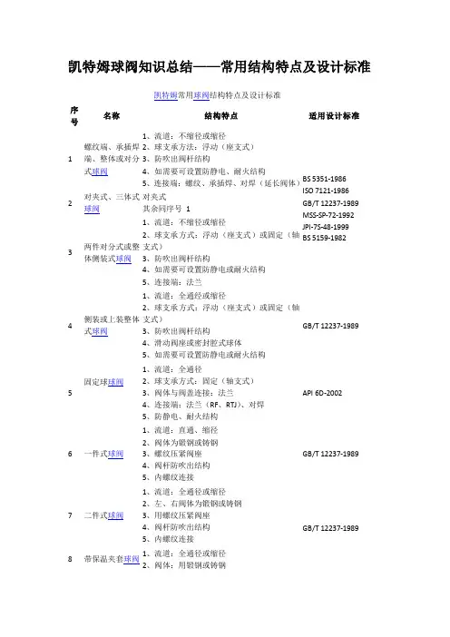
凯特姆球阀知识总结——常用结构特点及设计标准凯特姆常用球阀结构特点及设计标准序号名称结构特点适用设计标准1螺纹端、承插焊端、整体或对分式球阀1、流道:不缩径或缩径2、球支承方法:浮动(座支式)3、防吹出阀杆结构4、如需要可设置防静电、耐火结构5、连接端:螺纹、承插焊、对焊(延长阀体)BS 5351-1986ISO 7121-1986GB/T 12237-1989MSS-SP-72-1992JPI-7S-48-1999BS 5159-19822对夹式、三体式球阀对夹式其余同序号13两件对分式或整体侧装式球阀1、流道:不缩径或缩径2、球支承方式:浮动(座支式)或固定(轴支式)3、防吹出阀杆结构4、如需要可设置防静电或耐火结构5、连接端:法兰4侧装或上装整体式球阀1、流道:全通经或缩径2、球支承方式:浮动(座支式)或固定(轴支式)3、防吹出阀杆结构4、滑动阀座或密封腔式球体5、如需要可设置防静电或耐火结构GB/T 12237-19895固定球球阀1、流道:全通径2、球支承方式:固定(轴支式)3、阀体与阀盖连接:法兰4、连接端:法兰(RF、RTJ)、对焊5、防静电、耐火结构API 6D-20026一件式球阀1、流道:直通、缩径2、阀体为锻钢或铸钢3、螺纹压紧阀座4、阀杆防吹出结构5、内螺纹连接GB/T 12237-19897二件式球阀1、流道:全通径或缩径2、左、右阀体为锻钢或铸钢3、用螺纹压紧阀座4、阀杆防吹出结构5、内螺纹连接GB/T 12237-19898带保温夹套球阀1、流道:全通径或缩径2、阀体:用锻钢或铸钢3、浮动球:聚四氟乙烯阀座4、阀杆密封采用填料,用填料压套和压板压紧密封5、法兰连接6、阀体部位设有保温夹套9金属密封上装式气动球阀1、流道:全通径或缩径2、阀体、阀盖:用铬钼钢铸造3、中法兰连接:螺栓连接4、中法兰密封:采用密封环,阀座采用金属5、密封面均对焊硬质合金6、法兰连接API 6D-2002GB/T 12237-1989API 608-199510油密封式固定球球阀1、流道:全通径2、左、右阀体和球体采用铸钢或锻钢3、左、右阀体密封采用O形圈4、左、右阀体连接采用螺栓连接5、两阀座密封圈处均设有注油嘴6、阀杆与球体采用键连接7、与管道连接采用焊接或法兰连接8、密封圈采用聚四氟乙烯API 6D-2002GB/T 12237-1989API 608-199511滑动阀座浮动球球阀1、流道:全通径或缩径2、左、右阀体均为锻钢或铸钢3、左、右阀体用螺栓连接,其密封用垫片密封4、左、右阀体放密封圈处均为5°斜面,阀座密封圈可在5°斜面上自由滑动5、阀杆采用填料密封6、阀体底部设调整螺杆也采用填料密封7、连接方式:法兰连接GB/T 12237-1989API 608-199512前阀座密封固定球阀1、流道:全通径2、阀体、阀盖和球体采用铸钢或锻钢3、采用上装式阀体4、阀体阀盖采用螺栓连接5、采用浮动阀座、密封面采用聚四氟乙烯,阀座背后设有弹簧,前阀座台肩经过精确计算,保证进口阀座密封比压6、连接形式:法兰连接、焊接API 6D-2002API 608-199513后阀座密封固定球球阀1、流道:全通经2、阀体、阀盖和球体采用铸钢或锻钢3、采用上装式阀体4、阀体阀盖采用螺栓连接5、采用浮动阀座、密封面采用聚四氟乙烯,阀座背后设有弹簧,后阀座台肩经过精确计算,保证出口端阀座的密封比压API 6D-2002API 608-19956、连接形式:法兰或焊接14三体式固定球管线球阀1、流道:全通径2、中体、左、右阀体、球体采用铸钢或锻钢3、中体、左阀体、右阀体采用螺栓连接,密封垫密封4、球体采用上下阀杆固定5、在阀座密封圈的背后或台肩处设有碟形弹簧6、阀座采用聚四氟乙烯或金属7、上下阀杆处均设有轴承,上下阀杆采用O形圈密封8、连接形式:法兰连接或焊接API 6D-2002API 608-199515上装式固定球管线球阀1、流道:全通径2、阀体、阀盖、球体采用铸钢或锻钢3、阀体、阀盖采用螺栓连接,并由垫片保证密封API 6D-2002API 608-199516全焊接固定球管线球阀1、流道:全通径2、左、右阀体采用铸钢或锻钢3、整个阀组装好后,经试验合格后,左、右阀体再焊接到一起4、球体采用上、下阀杆固定5、上阀杆密封采用O 形圈,下阀杆密封采用垫片,然后密封焊,上、下阀杆处均设有轴承6、阀座的背后和台肩处设有碟形弹簧、阀座密封圈采用聚四氟乙烯或金属7、连接形式:法兰连接或焊接API 6D-2002API 608-199517全焊接浮动球阀1、流道:全通径或缩径2、阀体、球体采用钢板压制成形。
(新)-MSS SP-80-2003 青铜闸阀、截止阀、角阀和止回阀
Not for Resale
标准分享网 免费下载
Copyright MSS Provided by IHS under license with MSS No reproduction or networking permitted without license from IHS
--`,,,,,-`-`,,`,,`,`,,`---
Not for Resale
Copyright MSS Provided by IHS under license with MSS No reproduction or networking permitted without license from IHS
Not for Resale
标准分享网 免费下载
Copyright MSS Provided by IHS under license with MSS No reproduction or networking permitted without license from IHS
Not for Resale
Copyright MSS Provided by IHS under license with MSS No reproduction or networking permitted without license from IHS
--`,,,,,-`-`,,`,,`,`,,`---
Not for Resale
标准分享网 免费下载
--`,,,,,-`-`,,`,,`,`,,`---
Copyright MSS Provided by IHS under license with MSS No reproduction or networking permitted without license from IHS
Belimo B6300S-110 磨砂钢球阀数据表
B6300S-110•ApplicationStainless Steel Ball and StemType overviewTypeDN B6300S-11080Technical dataFunctional dataValve size 3" [80]Fluidchilled or hot water, up to 60% glycol Fluid Temp Range (water)0...250°F [-18...120°C]Body Pressure Rating ANSI Class 125, standard class B Close-off pressure ∆ps 175 psiFlow characteristic equal percentage Servicing maintenance-free Flow Pattern 2-way Leakage rate0% for A – AB Controllable flow range 75°Cv110Cv Flow RatingA-port: as stated in chart B-port: 70% of A – AB CvMaterialsValve body Cast iron - GG 25Stem stainless steel Stem seal EPDM (lubricated)SeatPTFE Characterized disc stainless steelPipe connection pattern to mate with ANSI 125 flange O-ring EPDM (lubricated)Ballstainless steel Suitable actuators Non-Spring ARB(X)SpringAFRB(X)Safety notesWARNING: This product can expose you to lead which is known to the State of California to cause cancer and reproductive harm. For more information go to Product featuresThis valve is typically used in air handling units on heating or cooling coils, and fan coil unit heating or cooling coils. Some other common applications include Unit Ventilators, VAV box re-heat coils and bypass loops. This valve is suitable for use in a hydronic system with variable flow.B6300S-110 Flow/Mounting detailsDimensionsType DNB6300S-11080ARB, ARXA B C D E F G I Number of BoltHoles9.6" [244]6.6" [168]12.2" [309]7.8" [198]3.9" [100]3.9" [100]6" [152]0.7" [19]4AFRB, AFRXA B C D E F G I Number of BoltHoles9.6" [244]6.6" [168]12.8" [325]9.4" [239]3.9" [100]3.9" [100]6" [152]0.7" [19]4B6300S-110ARXA B C D E F G I Number of BoltHoles13.3" [338]6.6" [168]15.0" [380]10.5" [267]3.9" [100]3.9" [100]6" [152]0.7" [19]4AFRXA B C D E F G I Number of BoltHoles16.0" [406]6.6" [168]16.6" [422]11.9" [302]3.9" [100]3.9" [100]6" [152]0.7" [19]4AFRXUP N4FootnotesNEMA 4, On/Off, Spring Return, AC 24...240 VTechnical dataElectrical dataNominal voltageAC 24...240 V / DC 24...125 V Nominal voltage frequency 50/60 Hz Power consumption in operation 7 W Power consumption in rest position 3.5 WTransformer sizing7 VA @ AC 24 V (class 2 power source), 8.5 VA @ AC 120 V, 18 VA @ AC 240 V / heater 25 VA @ AC 120 VElectrical Connection 18 GA appliance cable, 3 ft [1 m], with 1/2" conduit connectorOverload Protectionelectronic throughout 0...95° rotation Functional dataDirection of motion motor selectable by ccw/cw mounting Direction of motion fail-safe reversible with cw/ccw mounting Manual override 5 mm hex crank (3/16" Allen), supplied Angle of rotation 90°Running Time (Motor)75 s / 90°Running time fail-safe <20 s Noise level, motor 45 dB(A)Noise level, fail-safe 62 dB(A)Position indicationMechanical Safety dataDegree of protection IEC/EN IP66Degree of protection NEMA/UL NEMA 4XEnclosure UL Enclosure Type 4XAgency ListingcULus acc. to UL60730-1A/-2-14, CAN/CSA E60730-1:02, CE acc. to 2014/30/EU and 2014/35/EU Quality Standard ISO 9001Ambient temperature -22...122°F [-30...50°C]Ambient temperature note -40...50°C for actuator with integrated heating Storage temperature -40...176°F [-40...80°C]Ambient humidity Max. 100% RH Servicingmaintenance-freeMaterialsHousing material Die cast aluminium and plastic casing†Rated Impulse Voltage 800V, Type of action 1.AA, Control Pollution Degree 3Electrical installationINSTALLATION NOTESActuators with appliance cables are numbered.AFRXUP N4Universal Power Supply (UP) models can be supplied with 24 VAC up to 240 VAC, or 24 VDC upto 125 VDC.Provide overload protection and disconnect as required.Actuators may be powered in parallel. Power consumption must be observed.Parallel wiring required for piggy-back applications.Meets cULus requirements without the need of an electrical ground connection.Warning! Live electrical components!During installation, testing, servicing and troubleshooting of this product, it may be necessaryto work with live electrical components. Have a qualified licensed electrician or other individualwho has been properly trained in handling live electrical components perform these tasks.Failure to follow all electrical safety precautions when exposed to live electrical componentscould result in death or serious injury.Wiring diagramsOn/OffDimensions。
Spears球阀产品说明书
球 阀实用型球閥 (26XX 系列)注: 国家卫生基金会生饮水认证,单一 O 形环,安全 - T 型设计中心柱。
注: 国家卫生基金会生饮水认证,单一 O 形环,安全 - T 型设计中心柱。
工业用双油令球阀 (18XX 系列)注: 国家卫生基金会生饮水认证,两条 O 形环,安全 - T 型设计中心柱,有锁扣的“T”形把手,PTFE 垫座,可与 TU 2000 系列阀门互换。
注: 国家卫生基金会生饮水认证,单一 O 形环,安全 - T 型设计中心柱,标准“T”形把手,HDPE 垫座(有 PTFE 垫座选择),可与 TU 2000 系列阀门互换。
工业用三通双油令球阀 (47XX 及 50XX 系列)注: 国家卫生基金会生饮水认证,双条 O 形环,安全 - T 型设计中心柱,没有分支截流注: 国家卫生基金会生饮水认证,单一 O 形环,安全 - T 型设计中心柱,无阻挡密封垫座架阀门。
逆 止 阀工业用球形逆止阀 (45XX 系列)注: 国家卫生基金会生饮水认证,垂直分流或水平分流应用,必须在泵浦或转向分流前直管管径 10 倍远距离安装之,可与 TU 2000 系列阀门互换。
蝶式逆止阀 (54XX 系列)注: 小体积設計,垂直分流或水平分流应用,對逆流有快速反應但不重甩關閉,必须在泵浦或转向分流前直管管径 5 倍远距离安装之。
工业用摆动式逆止阀 (44XX 系列)注: 為大流量小波動,垂直或水平流向的應用設計,必须在泵浦或转向分流前直管管径 10 倍远距离安装之。
注: 国家卫生基金会生饮水认证,多重档次把柄,适合缓慢开关,不必移除阀体即可检修,4" 闸阀附带快速查看位置指示器。
注: 小体积設計,多重档次把柄适合缓慢开关,不必移除阀体即可检修,6" 阀附带快速查看位置指示器。
其他種類的閥門蝶阀 (72XXXX 系列)注: 干燥中心柱设计,316L 型不绣钢中心柱,O 形密封圈在全压下有紧密的密封性,偏位盘片降低磨损及减少工作扭矩,套件或锁孔内镶金属设计可选。
搏力谋调节阀资料-最新版
安装、水流方向和调试
52
安装注意事项
53
调试、维护和工程设计的注意事项
54
V8.2.09.2013 • 资料如有改动,恕不另行通知
2
产品概览
控制球阀和用于调节控制的角行程执行器
kv
控制球阀的流量特性
流量特性:等百分比
Y
额定压力: 三通, 4140kPa (DN15...25), 2760kPa (DN32...50) 二通, 2500kPa (DN15...50), 1600kPa (DN65...150)
DC (0)2...10V TR24-SR TRF24-SR LRQU24-SR
LRU24-SR LRF24-SR
NRFU24-SR NRQU24-SR
NRU24-SR SRQU24-SR
SRVU24-SR-5 SRFU24-SR-5
GRVU24-SR-7 GRKU24-MF-7
TR24 TR230-3 TRF24-2
连接 Kvs[m3/h] DN[mm] 二通 调节型
弹簧复位 快速运行
三态型
弹簧复位
连接 Kvs[m3/h] DN[mm]
螺纹连接
法兰连接 PN16
0.63 1.0 1.6 2.5 4.0 4.0 6.3 6.3 10.0 10.0 16.0 16.0 25.0 25.0 40.0 63 100 140 230 320
4
5 不锈钢阀球、阀轴 12
6 配流盘产生等百分比特性
7 内螺纹连接(ISO7/1)
6
8 镀镍锻造黄铜阀体 5
9 排水孔,避免结露聚积
10 执行器与阀体之间可以加装隔热垫片
11
11 法兰(ISO7005-2)