3起动系-汽车电器设备(英文版)
汽车电器复习

第一章汽车蓄电池及其检测维修一. 填空题1. 汽车蓄电池是一种以化学能形式储存电能的装置。
2. 蓄电池按照电解液性质不同可分为酸性蓄电池和碱性蓄电池两种。
3. 汽车上最常用的是_酸性蓄电池蓄电池。
4.普通铅酸蓄电池循环使用寿命约为300次。
5. 铅酸蓄电池正极板上活性物质是多孔性的二氧化铅,厚2.2mm。
铅酸蓄电池负极板上的活性物质是海绵状纯铅,厚1.8 mm。
6. 铅酸蓄电池的电解液是由蒸馏水和硫酸按一定比例配制而成。
相对密度一般为1.26±0.01g/cm3。
7. 普通铅酸蓄电池是由正极板、负极板、隔板、电解液、外壳、联条和接线柱等主要部件组成。
8. 汽车铅酸蓄电池电解液温度降低时,其内阻将会增大。
9. 影响汽车铅酸蓄电池容量的因素有极板的构造、放电电流、电解液温度和电解液密度。
10. 12-QW-105型蓄电池的含义是12V 电源启动型免维护,容量为105Ah11. 从汽车上拆下蓄电池时,应先拆负极,后拆正极。
12. 汽车酸铅蓄电池的启动容量分为常温和低温容量两种。
二. 选择题1. 蓄电池是将(A )的装置。
A.化学能转化为电能B. 热能转化为化学能2. 免维护蓄电池汽车行驶( B )km无需添加蒸馏水。
A.800B. 800003. 如果需要更换汽车铅酸蓄电池时,应先拆除(B)。
A.蓄电池正极线B.蓄电池负极搭铁线4. 起动铅蓄电池各单格内电解液面高出极板( B )mm。
A.5~10B.10~155. 从免维护蓄电池上部的密度观察玻璃窗口观察,如果呈现( A )颜色,表示蓄电池的容量状况良好。
A. 绿色B.白色三、判断题1. 蓄电池极板组中负极板总是比正极板少一片。
(×)2. 配制电解液时应将硫酸徐徐倒入蒸馏水中。
(√)3. 干荷电蓄电池的主要特点是正极板具有较高的储电能力。
(×)四. 简答题1.简述蓄电池的作用答:起动时,向起动机提供200A~600A(汽油机)或1000A以上(柴油机)的起动电流,起动发动机;单独向用电设备供电;协助发电机向用电设备供电;可以被充电;起稳定汽车电网电压的作用。
汽车电气设备构造与维修(第2版)任务单答案

《汽车电气设备构造与维修》(第2版)答案项目一汽车电气基础知识与识图任务检查汽车电气设备一、学习任务单答案1.汽车电气系统的作用是将电能转换成光能、热能或机械能输出。
2.现代汽车的电气设备种类和数量都很多,但总的来说由电源系统、起动系统、点火系统、照明与信号系统、仪表与报警系统、辅助电器系统、还有电子控制装置等组成。
3.汽车电源系统包括蓄电池和发电机两个主要部件。
4. 起动系统的作用是带动飞轮旋转使发动机曲轴达到必要的起动转速让发动机自行运转。
5. 点火系统的作用是将低压电(12V)转化为高压电(1万-2万伏),适时的让火花塞点燃气缸内的可燃混合气。
6.汽车照明和信号系统中照明装置包括前照灯、雾灯、示宽灯等,其作用是确保车辆内外一定范围内合适的亮度;信号装置包括电喇叭、转向灯、倒车灯、制动灯等,其作用是告示行人、车辆引起注意,提供安全行车所必需的信号。
7.汽车仪表包括发动机转速表、车速表、燃油表、冷却液温度表等。
8.汽车电器的主要特点有单线制、负极搭铁、两个电源、用电设备并联、大电流开关通常加中间继电器、低压直流供电、安装有保险装置和用电设备并联等。
9.熔断器的作用是当电路中流过超过规定的电流时,熔断器自身发热而熔断,从而切断电路,防止烧坏电路连接导线和用电设备,并把故障限制在最小范围内。
10.一般情况下,汽车上使用的操纵开关的触点容量较小,不能直接控制工作电流较大的用电设备,常采用继电器来控制它的接通与断开,达到小电流控制大电流的作用。
汽车上的继电器有很多,常见的有三类:常开式继电器,常闭式继电器和混合式继电器。
11.认知万用表,写出下图中划线所指万用表各部件名称或功能。
12.认知电气符号,在下图中写出符号所指电气的名称或意义。
二、工作任务单答案检查汽车电气设备工作任务单班级:姓名:1.车辆信息记录品牌丰田整车型号TV7161GLD 生产年月2010.03 发动机型号1ZR 发动机排量 1.6 行驶里程125000 车辆识别码LFMAPE2CXA01758922.直流电压测量(使用万用表对指定元件进行测量)元件名称万用表档位标准值测量值判定5号电池直流电压档20V量程 1.5V 1.5V 异常□正常□√汽车蓄电池直流电压档20V量程12V 12.2V 异常□正常□√3.交流电压测量(使用万用表对指定元件进行测量)元件名称万用表档位标准值测量值判定墙面电源插座交流电压档500V里程220V 218V 异常□正常□√4.电阻测量(使用万用表对指定元件进行测量)元件名称万用表档位标准值测量值判定色环电阻电阻档20K量程15KΩ14.5KΩ异常□正常□√导线电阻档200量程小于1Ω无穷大异常□√正常□5.直流电流测量(使用万用表对指定元件进行测量)元件名称万用表档位标准值测量值判定汽车漏电电流直流电流200m档小于50mA 40mA 异常□正常□√6.继电器及熔断丝测量(使用万用表对指定元件进行测量)元件名称针脚电阻值加电后电阻判定元件名称电阻值判定项目二 电源系统 任务一 检修蓄电池一、学习任务单答案1. 蓄电池是一个化学电源,靠内部的化学反应在充电时将 电 能转变成 化学 能储存起来,在放电时将储存的 化学 能转变成 电 能供给用电设备。
汽车电子电气系统概述(ppt 62页)
图 单线制
4.并联连接
各用电设备均采用并联, 汽车上的两个电源(蓄电 池与发电机)之间以及所 有用电设备之间,都是正 极接正极,负极接负极, 并联连接。
由于采用并联连接,所 以汽车在使用中,当某一 支路用电设备损坏时,并 不影响其他支路用电设备 的正常工作。
图 用电设备并联
5.负极搭铁
采用单线制时,蓄电池一个电 极需接至车架或车身上,俗称 “搭铁”。蓄电池的负极接车 架或车身称之为负极搭铁;蓄 电池的正极接车架或车身称之 为正极搭铁。负极搭铁对车架 或车身金属的化学腐蚀较轻, 对无线电干扰小。我国标准规 定汽车线路统一采用负极搭铁。
(5)辅助电器系统--舒适与安全
用来为驾驶员和乘客提供良好的工作条件 和舒适的乘坐环境。主要包括挡风窗玻璃 及洗涤刮水器、电动车窗、电动座椅、后 视镜、空调装置、音响设备、卫星导航和 定位系统及防盗装置。
3.汽车电气线路
现代汽车电气线路主要包括中央控制盒、 保险装置、继电器、电线束及插接件、电路 开关等,电路构成一个统一的整体。
汽车电子的发展方向
安全,环保,节能 传感器不断提高,数量增加 处理器升级换代 汽车系统升压 数据总线应用日益普及 智能汽车,智能交通ITS开始应用 嵌入式软件,硬件的设计开发 新技术在汽车电子产品的应用
1.2 汽车电气技术概述
现代电气设备种类及数量繁多,但总的来 说可以大致分为三大部分:电源、用电设备、 汽车电气线路。
(21世纪后)丰田普锐斯 电动轿车
(80年代)大众帕萨 特新领驭
(70年代)奥迪轿车
汽车电子电气系统组成
蓄电池 电子电火
发电机
保险丝盒
起动机
后窗加热除霜
前小灯
汽车电气设备与维修(第二版)(吴涛)1-5章 (4)
6
1.启动系统的组成 目前汽车上的启动系统一般由蓄电池、启动机和启动控 制电路组成,如图4.1所示。启动控制电路包括启动按钮或开 关、启动继电器、电磁开关等。 启动机是启动系统的核心部件。启动开关的作用是接通 启动机电磁开关电路,使电磁开关通电工作。汽油发动机的 启动开关与点火开关组合在一起,即点火开关设有启动挡。 一些汽车的启动机控制电路中装有启动继电器,由启动继电 器触点的开闭控制启动机电磁开关电路的通断,启动开关只 是控制启动继电器线圈电路的通断,减小了通过启动开关的 电流。
29 图4.8 电刷组件
30
4) 机壳 启动机的机壳是电动机的磁极和电枢的安装机体,大多 数一端有四个检查窗口,便于进行电刷和换向器的维护。机 壳中部有一个电流输入接线柱,并在内部与励磁绕组的一端 相连。启动机一般采用青铜石墨轴承或铁基含油滑动轴承。 减速启动机由于电枢的转速较高,采用滚柱轴承或滚珠轴承。 电刷装在前端盖内,后端盖上有拨叉座,盖口有凸缘和安装 螺孔,还有拧紧中间轴承板的螺钉孔。
M = Cm s
35
式中,Cm为电动机的转矩常数,取决于电动机的结构。Cm 与电动机磁极对数P、电枢绕组导线总根数Z及电枢绕组电路 的支路对数a有关,即Cm = PZ/(2 a)。
ቤተ መጻሕፍቲ ባይዱ
36
2) 直流电动机转矩自动调节过程 根据上述原理分析可知,电枢在电磁转矩M作用下产生转 动。由于绕组在转动时切割磁力线而产生感应电动势,根据 右手规则判定其方向与电枢电流Is的方向相反,所以称为反 电动势Ef。反电动势Ef与磁极的磁通量Φ和电枢的转速n成正 比,即
1 项目四 启动系统的检修
任务1 启动机的检修 任务2 启动系统的故障诊断 拓展知识 项目小结
2
6照明和信号系统-汽车电器设备(英文版)
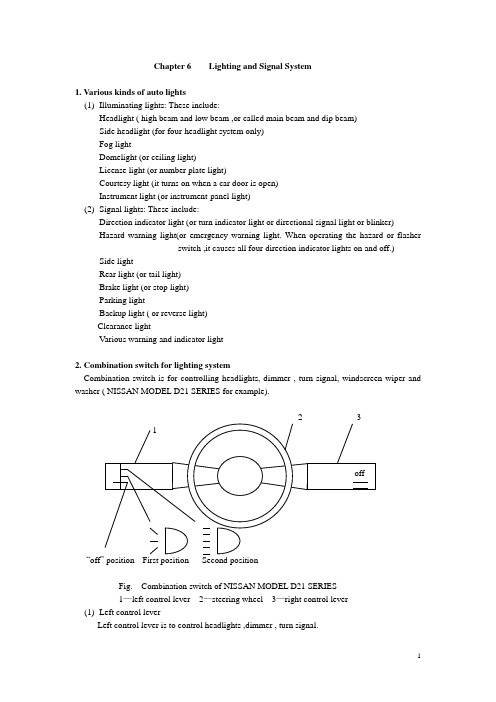
Chapter 6 Lighting and Signal System1. Various kinds of auto lights(1)Illuminating lights: These include:Headlight ( high beam and low beam ,or called main beam and dip beam)Side headlight (for four-headlight system only)Fog lightDomelight (or ceiling light)License light (or number plate light)Courtesy light (it turns on when a car door is open)Instrument light (or instrument-panel light)(2)Signal lights: These include:Direction indicator light (or turn indicator light or directional signal light or blinker)Hazard warning light(or emergency warning light. When operating the hazard or flasherswitch ,it causes all four direction indicator lights on and off.) Side lightRear light (or tail light)Brake light (or stop light)Parking lightBackup light ( or reverse light)Clearance lightVarious warning and indicator light2. Combination switch for lighting systemCombination switch is for controlling headlights, dimmer , turn signal, windscreen wiper and washer ( NISSAN MODEL D21 SERIES for example).“offFig. Combination switch of NISSAN MODEL D21 SERIES1—left control lever 2—steering wheel 3—right control lever(1)Left control leverLeft control lever is to control headlights ,dimmer , turn signal.●Lighting:Turn the switch to the first position: The side, tail, license plate and instrument panel lights will come on.Turn the switch to the second position: Headlights will come on and all the other lights remain on. To select the high beam, push the level forward. Pull it back to select the low beam.●Passing signal:Pulling the lever toward you will turn on the passing signal even when the headlight switch is “off”.●Turn signal:Move the lever up or down to signal to the turning direction. When the turn is completed, the turn signals cancel automatically.●Lane change signal:To indicate a lane change, move the lever up or down to the point where lights begin flashing.(2)Right control lever2—speed: “off”positionlow speed pull to washhigh speed2—speed with mist switch mist“off”positionlow speed pull to washhigh speed2—speed with intermittence “off”positionintermittentlow speed pull to washhigh speedTurn the ignition switch to “ACC” or “on” and move the lever down to operate the wiper.Move the lever up to wipe off a misty windscreen if this equipped. The wiper will operate only once.Pull the lever toward you to operate the washer.3. Relays and bulbs3.1 Relays(1)Function:Relays use a low control current to operate a solenoid, then the switch contacts can transmit very high working current.(2)Types of relaysThere are three basic types: normally-open (make)Normally-closed (break)Double-throw (changeover)88 86 85 88a 87 86 85 87a 87 86 85 88a 87aFig. Relays(3) Operation:A relay can be defined as an electromagnetic switch in which the contacts are actuated by asolenoid (an electromagnetic coil). The control current needed to operate the electromagnet is only 0.2 to 1 A, depending on the relay. However, the switch contacts can transmit very high working currents(up to 2000A for instance at the starting motor solenoid switch). It is advantageous to use a relay so that the high load between the electrical source and the consumer can be transmitted through a wire of generous cross-section and this can be kept short, whereas the control wire between the switch and the relay coil, which is subject to only very low loads, can be made as long as necessary.(3)Application:Relays are often used in horn, headlight, electric fuel pump, fog light and starting circuits.3.2 Light bulbs(1) Types of light bulbThere are two basic types according to the number of filament:Single-filament bulbDouble-filament bulbFor headlight bulbs, two types of common incandescent and halogen-wolfram bulbs can be of option.(3)Power selection of typical light bulbsBulb power should be selected according to the specifications. This is a example for Audi 100.Headlight 60 W/55 W (double filament for high beam and low beam,enclosed-type headlight)Side light 8 WStop light/tail light 21 W/5W (double filament)Direction indicator light 21 WReverse light 21 WLicense plate light 5 WFog light 55WParking light 4WDomelight 10WInstrument-panel light 2W4. Headlight4.1 Types of headlightThere two basic types of round and rectangular headlights according to the shape, and two types of semi-enclosed and enclosed (or vacuum) headlights according to the construction.The rectangular type has become increasingly popular in recent years. They fit the tapered front-end style of the modern cars.4.2 Headlight circuit:A typical headlight circuit is as shown below.dipswitchhigh beam leftlow beam lefthigh beam indicatorhigh beam rightlow beam rightside leftrear leftinstrument panelside rightrear rightlicense plate4.3 OperationRefer to the combination switch (left control lever).4.4 Headlight aimingAiming adjustment is made by turning screws in a spring-loaded holder. Top screw is for up-and-down adjustment. Side screw is for left-to-right adjustment.2Round type rectangular type1—Horizontal aim adjusting screw 2—Vertical aim adjusting screw4.5 Inspecting headlight circuitAccording to the different wiring circuit, checking procedures are different. Generally follow below.●Use public fuse: One bulb is not working. Check bulb or connection.Two or more bulbs are not working. Check fuse and switch.●Use separate fuse: One bulb is not working. Check fuse and bulbTwo or more bulbs are not working. Check switch or relay.5. Stop light (or brake light)Stoplight often uses double-filament bulbs, sharing with tail light. This is similar to those used in the headlights. The stop light must be brighter than tail light so that it can be seen in daylight.5.1 Stop light circuit:A typical stop light circuit is as shown below.5.2 OperationWhen depressing brake pedal, the stop light switch closes. Stop lights come on.5.3 Types of stop light switchThere are two basic types.Mechanical attached to brake pedalAttached to operating mechanismPressure-activated hydraulicPneumatic (for air pressure braking system)contactsspringterminalmechanical type pressure-activated typeFig. Schematic view5.4 Inspecting stop light circuit●One bulb is not working: check bulb or connection.●Two bulbs are not working: check fuse, then stop light switch. For checking stop lightswitch, you can directly connect two terminals and pinpoint whether the switch isoperative or not.6. Backup light (or reverse light)The backup lights come on when the shift lever is moved to“R”position. At the same time, the reverse alert device sounds.6.1 Backup light circuitA typical backup light circuit is as shown below.reverse lightFig. Simplified backup light circuit6.2 OperationWhen shifting into reverse, reverse switch is closed. Reverse light comes on. Meanwhile, current flows through horn and it sounds. At the same time, current also flows through coil L1 and coil L2. As two magnetic field directions are opposite, the resultant magnetic force is poor. Relay contacts remain closed. After the capacitor is charged, current and magnetic field in coil L2 disappears. The resultant field is strong enough to open the relay contacts. Horn stops sounding. Then the capacitor discharges through two coils. This resultant field keeps contacts still open until it discharges fully. Then relay contacts close again and horn resumes sounding. This cycle repeats while the reverse light switch is closed.6.3 Inspecting backup light circuit:●One bulb is not working: check the bulb or connection.●Two bulbs are not working: if it sounds, check the circuit.If it doesn’t sound, check fuse and switch.●Bulbs are on, but no sound: check the reverse alert device. (procedure: horn, contacts,capacitor, coils)7. Direction indicator lightThis is often called the flasher circuit. In this circuit, a flasher relay makes and breaks the current flow between 60 to 120 times every minute, so producing a flashing light.7.1 Direction indicator light circuitA typical direction indicator light circuit is as shown below.Front leftRear leftFig. Simplified direction indicator light circuit7.2 Types of flasher and operationThere are three types of flasher.(1)Hot wire type: It uses resistance wire. When current flows, it expends and contracts as itheats up or cools down, to operate contacts.(2)Capacitor type: It uses capacitor, charging and discharging. This activates the two coils tooperate the contacts. (Refer to backup light)(3)Electronic type: It uses capacitor, charging and discharging. This activates the triodes tooperate the circuit.When moving up or down the direction indicator switch, the flasher works and intermittently allows the current to flow. This will makes and breaks the right or left direction indicator light circuit to give a turn signal.7.3 Inspecting direction indicator light circuit●If one bulb is not working, check the bulb or connection.●If one-side bulbs are not working, check indicator switch.●If all bulbs are not working, check fuse, ignition switch, flasher unit.●If no flashing or kept on, check flasher unit.8. Electric hornMost horns are of the vibrating diaphragm type. To get a melodious sound, cars are often equipped with two horns of different tones. So it better to use horn relay to pass high current.8.1 Horn circuitA typical horn circuit is as shown below.8.2 OperationWhen depressing the horn button, horn relay is activated. Magnetic coil makes contact points close. Current flows from battery to horns through horn relay. The horns sound.8.3 Inspecting horn circuit●One horn loses sound: check horn or connection. Tune up horn if necessary.●Two horns lose sound: check fuse, horn button switch and relay.●Horn sound is low: check battery condition, relay contact points condition, and tune uphorns if necessary.8.4 Horn adjustment:●Tone adjustment: adjust the gap between iron core and iron armature in the horn.●Volume adjustment: adjust the pressure of contacts inside the horn by adjusting screw.9. Optical fiber lightingIn many cars, the instrument panel requires lights at many places to illuminate the speedometer, the indicating gauges, and the various controls. Because of the small spaces available, it becomes a problem to locate light bulbs where they are needed. To eliminate this problem, some cars use fiber-optic conductors. Theses conductors are made up of a very large number of extremely fine and flexible threads, or fibers , of pure glass which are bound together into a bundle, or cord. Each fiber has the property of being able to conduct light, even around bends or corners. As light starts down the fiber, it is reflected off the outer surface of the fiber. If the fiber is curved, the light keeps bouncing off the outer surfaces with little loss. By the time the light comes out the other end of the fiber, it is almost as strong as when it entered.Now, to utilize this effect, fiber bundles(each with many fibers) are run from a central light source to the various outlets on the instrument panel where light is needed. Therefore, only one light bulb is needed to provide light at many places. Installation and servicing problems are made easier to solve by the use of the fiber bundles. Only one light bulb needs to be replaced if a burnout occurs, the fiber bundles can be bent almost any way without damaging them.。
(完整版)汽车电气设备习题集及答案

( )
电解液注入铅蓄电池内以后,要静止放置5~
,才能进行充电。( )
硅整流充电机属于固体整流,没有旋转件和易
( )
三、问 答
什么叫做定电流充电法、定电压充电法、混合
什么叫做初充电、补充充电?
定电流充电有什么优点?
混合充电法有什么优点?
在什么情况下要进行补充充电?
第七节 新蓄电
( )
电解液的标准温度各国都不一样,我国的标
20℃。( )
加液孔盖是密封的,主要防止电解液逸出和
( )
极桩的截面积上下大小是一样的,以防止导
( ) 13.东风EQ1090装有两个6-Q-105型干封式铅蓄电池。( ) 14.铅蓄电池的串联目的是提高蓄电池的额定电压。( ) 三、问 答 题 1.铅蓄电池的联接有哪几种形式? 2.铅蓄电池的型号由哪五部分组成?写出每一部分的含义。 3.试解释解放牌CA1091汽车用的6-QA-100型铅蓄电池各部分的意义? 第三节 铅蓄电池的工作原理 二、判断题(正确的打“√”,错误的打“×”) 1.铅蓄电池的放电过程是化学能转变成电能的过程。( ) 2.在放电过程中,正负极板上的二氧化铅和纯铅都变成新的化合物稀硫酸。( ) 3.在放电过程中,电解液相对密度是逐渐升高的。( ) 三、问 答 题 1.为什么说充电终期充电电流不宜过大? 2.影响铅蓄电池寿命的因素主要有哪些? 3.怎样延长铅蓄电池的使用寿命? 第四节 铅蓄电池的特性 二、选择题(将正确答案的序号填在括号内) 1.铅蓄电池电动势的大小,取决于( )。 A.电解液的相对密度和温度;B.电解液中的硫酸和水;C.内电阻和端电压 2.铅蓄电池的内阻大小主要是( )。 A.极板的电阻;B.电解液的电阻;C.隔板的电阻 3.铅蓄电池放电时,端电压逐渐( )。 A.上升;B.平衡状态;C.下降 三、问 答 题 1.什么叫做电动势、端电压、内电阻? 2.铅蓄电池放电终了有什么特征? 3.铅蓄电池充满电时有什么特征? 4.解放牌汽车CA1091装有一个6-QA-100型干荷式铅蓄电池,试计算其总内阻多少?单格电池的内阻是多少? 第五节 铅蓄电池容量及影响因素 二、判断题(正确的打“√”,错误的打“×” 1.铅蓄电池的标准容量是在一定条件下,恒定放电电流与时间的乘积。( ) 2.常温起动容量是指电解液温度为30℃时的起动容量。( ) 3.低温起动容量是指电解液温度为0℃时的起动容量。( ) 4.放电电流越大端电压下降越快。( ) 三、问 答 题 1.什么叫额定容量、起动容量? 2.影响铅蓄电池容量的主要因素有哪些?
汽车电器设备构造与维修第2版课件-汽车电气设备参考答案
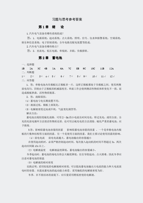
习题与思考参考答案第1章绪论1.汽车电气设备有哪些系统组成?答:1.电源系统;起动系统;点火系统;照明、信号、仪表和报警系统;空调系统;娱乐和信息系统;电子控制系统;全车电路及配电装置等组成。
2.汽车电气设备有哪些特点?答:2.直流电;低压电源;单线制、并联;负极搭铁。
第2章蓄电池一、选择题1B 2A 3C 4B 5A 6A 7C 8B 9C 10C 11B 12A二、判断题1× 2× 3× 4√ 5√ 6√ 7× 8√ 9× 10√ 11√ 12√三、问答题1.答:单格电池内负极板比正极板多一片,这样正极板都处于负极板之间,使其两侧放电均匀,否则由于正极板的机械强度差,单面工作会使两侧活性物质体积变化不一致,而造成极板拱曲,活性物质脱落。
2.答:故障原因:(1)蓄电池亏电长期放置不用;(2)液面过低,极板上部氧化;(3)电解液密度过高或不纯,气温变化剧烈等。
解决方法:蓄电池出现轻度硫化故障,可用2~3A的小电流长时间充电,即过充电;或用全放、全充的充放电循环方法使活性物质还原。
也可用去硫充电的方法消除。
硫化严重的蓄电池,应予报废。
3.答:影响铅蓄电池容量的因素影响铅蓄电池容量的因素,一个是单格电池内极板的片数和结构等方面的因素,另一个是使用方面的因素,我们主要讨论使用因素的影响。
(1)放电电流放电电流越大,蓄电池输出的容量越小在使用起动机时,必须严格控制起动时间,每次接入起动机的时间不得超过5s,两次起动应间隔15s以上。
(2)电解液温度电解液温度降低,蓄电池输出的容量减小,冬季起动时,蓄电池的端电压将会大幅度降低,往往导致起动、点火困难,因此冬季应注意对蓄电池的保温(3)电解液的相对密度实践证明,采用较低的电解液相对密度,可以提高蓄电池输出大电流的能力和大电流放电时的容量。
从提高蓄电池的起动能力来看,采用偏低的电解液密度为好。
冬季,在不致结冰的前提下,应尽量采用稍低密度的电解液。
汽车电器与电子设备介绍

车道保持辅助系统 (LKA):帮助驾驶 员保持在车道内行驶, 避免偏离车道
盲点监测系统 (BSD):监测车 辆后方盲区,避免 变道时发生碰撞
01
02
03
04
提高驾驶舒适性
01
自动空调:根据车内温度自动调节,保持舒适的驾驶环境
02
座椅加热/通风:提供冬暖夏凉的座椅,提高驾驶舒适性
03
音响系统:提供高品质的音乐享受,减轻驾驶疲劳
路线规划等
智能后视镜等
操作简便
人性化
汽车音响系统
汽车音响系统是汽车电器与电子设备的重要组 成部分,用于提供音乐、广播等娱乐功能。
汽车音响系统包括主机、扬声器、功放等设备, 可以提供高质量的音乐播放和音效调节。
汽车音响系统可以连接手机、MP3等设备, 方便用户播放自己喜欢的音乐。
汽车音响系统还可以与导航、倒车影像等设 备联动,提供更加便捷和安全的驾驶体验。
汽车安全系统
防抱死制动系统(ABS): 防止车轮抱死,提高制动
效果
电子稳定程序(ESP): 防止车辆侧滑,提高行驶
稳定性
安全气囊:在碰撞时保护 乘客,减少伤害
倒车雷达/影像:辅助倒 车,避免碰撞障碍物
盲点监测系统(BSD): 监测盲区,避免变道时发
生碰撞
自动紧急刹车系统 (AEB):在紧急情况下
自动刹车,避免碰撞
04
导航系统:提供实时导航信息,避免迷路和走错路,提高驾驶舒适性
提高驾驶效率
导航系统:实时提供路线规划, 避免拥堵和绕路
自适应巡航控制:自动调整车速, 保持安全距离,减轻驾驶疲劳
车道保持辅助:自动修正方向, 避免偏离车道,提高行车安全
自动泊车系统:自动识别车位, 完成泊车操作,节省时间
- 1、下载文档前请自行甄别文档内容的完整性,平台不提供额外的编辑、内容补充、找答案等附加服务。
- 2、"仅部分预览"的文档,不可在线预览部分如存在完整性等问题,可反馈申请退款(可完整预览的文档不适用该条件!)。
- 3、如文档侵犯您的权益,请联系客服反馈,我们会尽快为您处理(人工客服工作时间:9:00-18:30)。
Chapter 3 The Starting System1. Operation and purposeThe battery sends current to the starting motor when the driver turns the ignition switch to START. This causes a pinion gear in the starting motor to mesh with teeth on the ring gear around the engine flywheel.The starting motor then rotates the engine crankshaft for starting,2. DC electric motorBasic principle of DC electric motorWhen current from the battery flows through the loops of motor rotor, a strong magnetic field is produced around the loops. This magnetic field opposes the magnetic field of the stationaryIt consists of :2.2.1Magnetic polesIt consists of : (magnetic)pole shoesmagnetic field windings (or stationary field windings)Usually there are 2 couples of magnetic poles ( or 4 poles). Heavy-duty motors have 3 couples of magnetic poles (or 6 poles).2.2.2 ArmatureIt consists of : laminated core (or lamination core)armature windings (or armature loops or armature conductors)The wiring connection of magnetic field windings and armature windings is often adopted in series connection. These are two basic ways of connection.21— magnetic field windings ; 2—armature windings2.2.3 Commutator assemblyIt consists of : commutator (on armature shaft)electric brushes , brush holders and springsCharacteristics of DC electric motor2.3.1 Properties of DC electric motor(1) Great starting torque.(2) High speed at low load and low speed at high load. This property ensures reliable startingof engine.2.3.2 Characteristic curves of DC electric motorDefinition:Characteristic curves of DC electric motor describe the relations of torque M, speed n, and power P with electric current I , or M=f(I), n=f(I), P=(I).I 0 racing 2max II max locked I(1) When just starting, n=0, I is max(lock current), M is max.for starting.(2) When no load existing, n is max., I is min., M is min.(3) At the middle point 2maxI , P is max.Parameters selecting of starting motor2.4.1 Power selecting9550n M Q Q P ≥(KW) n Q ―Min. engine-starting speed. for gasoline engine,50~70rpm. for diesel engine, 100~200rpm M Q ―S tarting resistant torque: including friction, compression lossand accessory mechanism lossTherefore, through testing ,the essential power for starting motor is :For gasoline engine: P=(0.18~0.22)L (KW) L ―E ngine displacementFor diesel engine: P=(0.74~1.1)L (KW) L ―E ngine displacement2.4.2 Gear ratio selectingZ Z n n S F F S i ==n s ―M otor speed ;n F ―C rankshaft speed for starting,n F =n QZ F ―T ooth number of ring gear of flywheelZ s ―T ooth number of drive pinion of motorWe can obtain the motor speed through matching with the Max.P from the characteristic curves. In fact, practical gear ratio is smaller than the optimum gear ratio because of Z F design problem. Generally, for gasoline engine, gear ratio is 13~17; for diesel engine, gear ratio is 8~102.4.3 Battery capacity selectingBattery capacity can be decided according to the rating power of starting motor. The empirical formula is:UP C )800~600( C ―battery capacity, Ah P ―rating power of starting motor, KWU ―rating voltage of starting motor, 12V3. Construction and control of starting motor3.1 Types of starting motorThere are two types of starting motors: inertia type and pre-engaged typeThe inertia type is a simple motor that the armature spindle carries an inertia-engaged drive arrangement consisting of a pinion mounted on a screwed sleeve.When the motor is operated, the sudden movement screws the pinion along the sleeve into mesh with the flywheel ring gear,when its movement is arrested by a strong buffer spring. As the engine starts and the driver releases the starter switch, the flywheel spins faster than the motor pinion, forcing it out of mesh.The pre-engaged type are almost always fitted to heavy diesel engines, and can be found on many modern cars. They differ from the inertia drive because the pinion is fully engaged with the flywheel before the starting motor starts to spin. This is achieved by mounting the solenoid switch on top of the motor and connecting it to a lever whose other end engages with the pinion. Activation of the switch draws in the solenoid, which pulls the lever and moves the pinion into mesh with the flywheel ring gear.In the last part of the lever movement the contacts are bridged that link the motor to the battery. Pre-engagement of the pinion greatly reduces the wear on the flywheel ring gear.3.2 Construction and control of starting motor(pre-engaged type)It consists of :(1) DC electric motor(2) Driving mechanismThis includes driving pinion,overrunning clutch,shift lever(or fork),clutch spring,etc.(3) Control equipmentThis includes two ways of control: mechanical control and electromagnetic control.3.2.1 Overrunning clutch(1) Types of overrunning clutchThere are three types: Roller type (most vehicles use)Spring typeFriction disk type(2)Function●Transmit cranking force to the engine flywheel.●Prevent the engine flywheel from driving the starting motor.(3)Construction and operation (roller type for example)It consists of outer shell and pinion, rollers, plungers and springs, cross block.In fact,the overrunning clutch is also called one-way clutch.●When starting engine:The rollers lock outer shell and cross block, outer shell andpinion drive flywheel to rotate.●After starting engine: The flywheel velocity is greater than starting motor velocity.The outer shell begins to rotate with flywheel. This action makes the overrunningclutch slip.3.2.2 Solenoid switch and control operationConstruction:It consists of: plunger(or moveable core), return spring, pull-in or winding, hold-in orControl operation:The solenoid switch has two windings, a pull-in winding(in series connection with the windings of DC electric motor )and a hold-in winding(in parallel connection with the windings of DC electric motor). They work together to pull the plunger in. This combination of windings (resultant magnetic force) provides sufficient magnetic strength to mesh the pinion and close the witch(this switch allows full motor current to flow). After the pinion is meshed and the switch is closed, less magnetism is required to hold the plunger in. Consequently, as the switch closes, the pull-in winding is shorted out, since it is connected between the two solenoid terminals. This makes a full current flow through the motor and the motor rotates at normal speed.4. Operating principle of starting motorOn starting motors with overrunning clutches, a solenoid switch is commonly used to produce the clutch-shifting action. The solenoid contains a pair of winding that are connected to the battery when the starting switch is closed. This produces a magnetic field that pulls a plunger in. The plunger movement causes a shift lever to move the overrunning clutch on the armature shaft. This shifts the overrunning-clutch pinion into mesh with the flywheel teeth. At the same time, the plunger movement forces a heavy switch to connect the starting motor directly to the battery. Now, cranking begins.5. Inspecting the starting motor unitsThis includes inspecting overrunning clutch, commutator, armature windings, magnetic field windings, brush and brush spring, solenoid switch,etc.6. Starting system troublesThere are two basic starting system troubles:(1)The starting motor does not crank the engine.(2)The staring motor cranks slowly, but the engine does not start.6.1Starting motor does not crank the engineThe most likely cause of this condition is a run-down battery. But there could be other causes. Turn on the headlights, and try cranking. There are five possibilities.(1)No cranking, no lightsThis is probably due to a completely dead battery. It could be caused by a bad connection at the battery or starting motor or an open fusible link(which indicates a short or ground in the system.(2)No cranking, but lights go out as you turn the key to START.This usually indicates a bad connection at the battery. It could also be due to a nearly dead(discharged) battery.Try wiggling the battery connections to see if this helps.(3)No cranking, and lights dim only slightly as you try to startThe trouble probably is in the starting motor. The pinion may not be engaging with the flywheel. If the starting-motor armature spins, the overrunning clutch is sleeping.(4)No cranking, and lights dim heavily as you try to startThis is most likely due to a run-down battery. It could be low temperature, too. The battery is much less efficient at low temperatures, and the engine oil is much thicker. This combination could prevent cranking, even though the battery is in fairly good condition. Also, the starting motor or engine could be jammed, or locked.(5)No cranking, and lights stay brightListen to hear if the magnetic solenoid is pulling the plunger in. you can hear this as a loud click. If nothing happens when you try to start , check the solenoid. Connect one end of a jumper wire to the solenoid battery terminal. Connect the other end to the small terminal on the solenoid that is connected to the ignition switch. If nothing happens, the trouble is in the solenoid. If the solenoid and starting motor work with the jumper wire connected, the trouble is in the ignition switch, or the wires connecting them.6.2Engine cranks slowly but does not startIt is very likely due to a run-down battery or defective battery. The battery is unable to spin the starting motor at normal speed. Low temperature could also be a factor here.It is also possible that the driver may have run the battery down trying to start. Some condition in the engine, or the fuel or ignition system, is preventing normal starting. The driver continued to try, however, until the battery ran down.7. Sliding-armature starting motorIt is used for heavy –duty diesel engine in particular.1―main winding 2―auxiliary winding 3―holding winding 4―solenoid switch5―stationary contact-point 6―tumbler bridge 7―release lever 8―locking paw9―return spring 10―release disk 11―armature 12―magnetic pole13―friction-disk clutchIn its rest position , the armature is displaced axially out of the field windings. The pinion is driven from the armature shaft by way of a multi-plate clutch(friction disk type). The starting motor has three field windings: the auxiliary winding, the holding winding(shunt-wound) and themain winding(series-wound). To permit the armature to move axially, it has extra-long bearings and a wide commutator. There is also a return spring, a control relay(or solenoid switch) with tumbler bridge and a locking paw with release disk.Engagement is in two stages. In stage 1, the armature is displaced by the magnetic field of the auxiliary and holding winding, so that the pinion engages with the flywheel ring gear, aided by the armature rotating slowly. In stage 2, the release disk on the commutator raises the release lever to switch on the second stage of the control relay. The main winding is then energized by way of the tumbler bridge in the control relay.A multi-plate clutch is installed between the armature and the pinion. It ensures that the drive is taken up smoothly between armature and pinion after the pinion has engaged with the flywheel ring gear. If the ring gear begins to drive the pinion after the engine has started, the clutch is freed and acts like a freewheel. This prevents dangerous acceleration forces from reaching the armature of the starting motor as the engine speeds up. If a given torque is exceeded at the pinion, the multi-plate clutch interrupts the power flow between armature and ring gear(overload protection). This minimizes loads on the starting motor,pinion and ring gear.8. Gear-reduction starting motorThis starting motor has a gear reduction which increases cranking torque. The shift lever(or fork)is enclosed. When it is actuated by the solenoid, it shifts the overrunning-clutch pinion into mesh with the flywheel. The gear ratio between the armature and flywheel, due to the extra gears(the gear ratio of this gear reduction is about 3~4), is 45 : 1 for example. The armature turns 45 times to turn the flywheel, and the engine crankshaft, once. This provides a high cranking torque for starting.There are three types of gear-reduction mechanism:Internal gearing typeExternal gearing typePlanetary gearing type9. Permanent magnet starting motorThis motor uses permanent magnet instead of magnetic field winding. It has some advantages such as simple construction, small volume and weight. But its power is low and the magnetism is reduced as time goes on.。