柱塞泵毕业设计外文文献翻译【范本模板】
机械毕业设计英文外文翻译588柱塞式液压缸、起重器和柱塞

附录A译文(一) 柱塞式液压缸、起重器和柱塞液压缸、起重器和柱塞的基本术语可以被看作为同义词。
通常首先描述的是其基本质特征,“jack”通常用来描述,应用于起重器中的液压缸,而且在大多数应用驱动器的特定工业场合来提供起重装置,“ram”经常被应用于高输出力的大型、重型液压缸,其它一些权威书籍可能将“ram”定义为活塞和杆是相同直径的液压缸,尽管这种液压缸更准确的应该被叫做柱塞式油缸,或置换式液压缸,这些形式的液压缸单一作用式并有其相对的应用局限。
液压缸可为单作用式,在单作用液压缸情况下,运动由弹簧或某种外力或重力使活塞返回到起始位置时释放压力来完成,在这种情况下弹簧返回,再液压条件下可获得的输出力可以被弹簧抗力所减轻。
双作用液压缸再普通应用场合是最常用的,液流上被安装液压缸两端,被选择器交替实现输入口,输出口作用。
最大的可获得的输出的仅比单作用液压缸所获得的输出稍小些,因为当液体压力被反向加压时组织泄露,因而增加了摩擦力抵抗运动。
在反向运动时,可获得的力会由于活塞和杆面积的不同而降低了活塞作用面积减少,反向压力也是存在的,这种性能损失也许会很小,但在实际中明显地减少理论性能,而且液压缸的理论性能是有一定规格的,允许的公称公差以适应摩擦损失。
大多数的液压缸是单杆式的,双杆式的液压缸可能被应用在要求特高刚度下。
对于双作用式液压缸,冲压力在伸出和缩回是相等的,这里可以估计到相比在相同直径的液压缸由于杆的封闭作用,摩擦力也会两端的密封杆和密封轴承而增大。
液压缸被广泛用于工业液体系统中,这些液压缸也别称为线性原动机或往复原动机。
通常液压缸由循环管,活塞和杆运动处两侧的密封组织,活塞杆可被设计在液压缸的一侧或两侧,围绕活塞杆向液压缸外的液体温度可以由正确设计的还有密封垫用途的应用。
再这当中我们将学习各种类型的液压缸以及它们是如何应用的液压缸的用途会对工业水利学的学习有很大帮助。
(二) 液压动力钳的发展近年来,随着我国国民经济的持续快速发展,我国的石油消费量逐年增加。
柱塞泵毕业设计外文文献翻译
柱塞泵毕业设计外⽂⽂献翻译利⽤神经⽹络预测轴向柱塞泵的性能Mansour A Karkoub a, Osama E Gad a, Mahmoud G Rabie ba--就读于科威特的科威特⼤学⼯程与⽯油学院b--就读于埃及开罗的军事科技⼤学摘要本⽂推导了应⽤于轴向柱塞泵(斜轴式)的神经⽹络模型。
该模型采⽤的数据是由⼀个实验装置获得的。
这个正在进⾏的研究的⽬的是降低柱塞泵在⾼压下⼯作时的能量损耗。
然⽽,在最初我们要做⼀些研究来预测当前所设计的泵的响应。
神经⽹络模型具有前反馈的结构,并在测验过程中使⽤Levenberg-Marquardt优化技术。
该模型能够准确地预测柱塞泵的动态响应。
1、简介可变排量轴向柱塞泵是在流体动⼒系统中经常要⽤到的重要设备,如液压动⼒供应控制和静液压传动驱动器的控制。
本装置具有变量机制和功率-重量⽐特性,使其最适合于⾼功率电平的控制。
所设计的这种轴向柱塞泵拥有可靠性和简便的特点,然⽽其最重要的特征是可以变量输出。
⼈们在轴向柱塞泵领域已经做了很多研究,但是本⽂将只论述⼀下少数⼏⼈所做的贡献。
Kaliafetis和Costopoulos[5]⽤调压器研究了轴向柱塞变量泵的静态和动态特性。
所提出的模型的精确度依赖于制造商提供的动态运⾏曲线等数据。
他们得出结论,运⾏条件对泵的动态⾏为是⾮常关键的,⽽泵的动态⾏为可以通过减⼩压⼒设定值进⾏改善。
Harris等⼈[4]模拟和测量了轴向柱塞泵的缸体压⼒和进油流量脉动。
Kiyoshi和Masakasu[7]研究了斜盘式变量输送的轴向柱塞泵在运⾏时刻的实验上和理论上的静态和动态特性。
并提出了⼀种新的⽅法来预测泵在运⾏过程中的响应。
也对研究泵特性的新⽅法的有效性进⾏了实验验证,实验中使⽤了⼀个有宽、短⽽深的凹槽的配流盘。
Edge和Darling[2]研究了液压轴向柱塞泵的缸体压⼒和流量。
这个得出的模型经过了实验检验。
对于配流盘、缸体上设计的退⼑槽和泵的流量脉动对泵特性的影响都进⾏了验证。
吉林大学机械学院本科毕业设计外文翻译格式

本科生毕业设计(论文)翻译资料中文题目:配合新一代液力变矩器的柴油动力线的一些特性英文题目:some properties of a diesel driveline with hydrodynamic torque converters of thelastest generation学生姓名:学号:班级:专业:机械工程及自动化指导教师:吉林大学机械科学与工程学院Some properties of a diesel drive line withhydrodynamic torque converters of the latestgenerationAbstractDynamic properties of a drive line with a controlled Diesel engine, hydrodynamic transmission mechanism, additional gearing and a loading-working machine producing common monoharmonic loading are investigated. Solution of the dynamic problem is based on phenomenological experimental data: drivingtorque-speed characteristic in the part of the prime mover and so-called external static characteristic in the hydrotransmission part. The non-linear task is solved by a modified harmonic balance method that was described in preceding publications by the author.Keywords: Machine drive line; Controlled Diesel drive; Hydrodynamic torque converter; Working machine; Periodic loading; Stationary dynamic stateNomenclature and abbreviationsa, b --- ------Coulomb and viscous non-dimensional friction lossesA i,B i --- ----coefficients in mathematical expression of torque-speed characteristic i, i m ----------kinematic transmission, supplementary gearing transmission ratio -------mean reduced moment of inertia in driving and loading partI, I, k K ---------tangent slopes of λ(i) and K(i) curves respectivelykλK -------------moment transmissionM ------------Diesel-engine momentM D(ω, z) ----controlled torque-speed driving characteristicM Dmax(ω), M Dmin(ω) ---torque-speed characteristic for maximal and minimal fuel supplyM1, (), M2, () ---pump loading moment and turbine driving momentM T1, M T2 ----friction loss moment in driving and loading partM z, M za ----mean value and amplitude of loading moment-------------hydrodynamic converter characteristic radius吉林大学本科毕业论文外文翻译t -------------timeT, T D------------Watt regulator and Diesel-engine time constantu, z ---------gas lever and regulator displacementw -----------common dynamic variableε -----------regulator structural parameterζ -----------regulator damping ratioλ -----------coefficient of rotation momentν -----------loading angular velocity, π-------index denoting mean value and periodical component---------hydraulic medium density----------rotation angleω1, (), ω2 ---pump and turbine angular velocityDM ------Diesel-engineG, G D ---additional and Watt-regulator gearingHdPT ---hydrodynamic power transmissionIJ --------InjectorLM ------loading mechanism (working machine)P, R, T---pump, reactor, turbineArticle OutlineNomenclature1. Introduction2. Mathematical model of the system3. Stationary dynamic solution at monoharmonic loading4. Results evaluation and concluding remarks1. IntroductionDynamic properties of a drive line (actuating unit) consisting of a controlled Diesel engine (DM), hydrodynamic power transmission system (HdPT), additional gearing (G) and a loading mechanism (LM) or working machine are investigated. The working machine loads the prime mover and the transmissions with a prescribed moment. A simple idealised schematic layout of the complete system is given in Fig.1. The considered Diesel engine is a standard production: ZETOR 8002.1 controlled by a mechanical (Watt’s) or electronic regulator R D governing fuel injector IJ. In the place of the hydrodynamic power transmission there are gradually applied hydrodynamic torque converters of the latest generation that have been projected吉林大学机械科学与工程学院and tested in WUSAM (Research and Projecting Institute of Machines and Mechanisms), j.s.c. Zvolen, Slovakia. These converters represent a three component assembly composed of a rotational pump (P), turbine (T) and a reactor (R) that may revolve in one direction as a free wheel. Advantage of these converters is the fact that their external dimensions and the dimensions of their individual components are identical and they may be mutually changed and arbitrarily combined in order to reach demanded properties. They differ only by internal configuration and blade geometry. According to [1] up to now more than 70 various types have been experimentally tested and from them the ones have been chosen that optimally fulfilled required properties. The mechanical system under consideration represents a sophisticated energy transfer chain from a source––prime mover to working mechanism. Because every real drive is of finite power, any periodic loading always evokes vibrations of all the dynamic variables even though we suppose all the connecting shafts and gearings rigid and backlash free. The influence of dynamic loading on the prime mover may be just controlled by a suitable choice of the torque converter.Fig. 1. Schematic layout of the Diesel drive line.In the paper influence of constant and periodic loading on time course of all the dynamic variables of the system (and particularly on the variables of the prime mover) is investigated at application of some selected types of hydrodynamic torque converters of the latest generation. For fulfilling this task it is necessary to create a suitable mathematical model of the whole combined system and then find its stationary solution corresponding to a required loading.2. Mathematical model of the system吉林大学本科毕业论文外文翻译At the beginning it is necessary to emphasize that mathematical modelling of the drive line in question is based, in our approach, on knowledge of the published phenomenological data: stationary torque-speed characteristic of the prime mover and so-called external static characteristic of the applied hydrodynamic torque converter. It is a much simpler process than modelling based on thermodynamic equations of burning fuel mixture in the Diesel engine and on hydrodynamic equations of real streaming working medium in very complicated cavities of the torque converter. The characteristics are usually given by manufacturer of the individual system components. This is different and simpler approach to solution of the problem than one may find e.g. at Ishihara [2], Hrovat and Tobler [3], Kesy and Kesy [4], Laptev [5] and some others. The derived dimensional and non-dimensional mathematical models of the mechanical system are introduced in [6]. Thenon-dimensional, reduced, so-called single-shaft model (in the driving and loading part), was derived in the form of combined system of the following differential and algebraic equations:(1)(2)(3)(4)M2=KM1, (5)λ=λ(i), (6)K=K(i), (7)(8)吉林大学机械科学与工程学院(9) where the meaning of the individual symbols is explained in nomenclature. In the non-dimensional model all the dynamic variables and parameters are expressed by means of properly chosen relative standard quantities so that the model of the system might be the most simple. Transformation of the original equations system to the non-dimensional form Figs. (1), (2), (3), (4), (5), (6), (7), (8) and (9) is described in detail in [6]. As for this cited paper, it is necessary to say that the relative standard value of loading angular frequency has been settled according to the relation, where in denominator is relative standard value of time. For this value,the time constant of the regulator has been just chosen, i.e. , where therelated dimensional dynamic variables are distinguished by upper bars. The introduced mathematical model has nine variables: M, M1, ω1, z, λ, K, i, M2, ω2 and their meaning is explained in nomenclature. The first three equations represent mathematic model of the prime mover where in inertia moment I there is includedinertia moment of the pump and equivalent part of the working medium because driving and pump shafts are connected by a rigid clutch. The right side of Eq. (3) represents the controlled stationary torque-speed characteristic for which it holds: M D(ω1,z)=M Dmax(ω1)-[M Dmax(ω1)-M Dmin(ω1)]z, (10) where M Dmax(ω1), M Dmin(ω1) represent its non-dimensional extreme branches for maximal and minimal fuel supply and z is the non-dimensional regulator deviation.If the experimentally measured dependences M Dmax(ω1), M Dmin(ω1) are expressed by second degree polynomials then the controlled non-dimensional torque-speed characteristic has the form:(11) From the introduced model it is evident that at chosen parameter value u driving speed growth causes regulator displacement to increase and fuel supply to decrease. The idealised controlled torque-speed characteristic for a chosen parameter value u (gas lever displacement) is schematically depicted in Fig. 2. From Eq. (2) it is evident that the structural parameter ε must be chosen in such away that regulator self-oscillations should not occur. Eqs. Figs. (4), (5), (6), (7) and (8), in the sense of considerations in [6], represent the dynamic equations of the torque converter. Eq. (9) represents simplified motion equation of the loading mechanism under assumptiondoes not depend on rotation angle . In thisthat the reduced inertia moment Ireduced inertia moment there is involved inertia moment of the turbine with吉林大学本科毕业论文外文翻译equivalent part of the working medium too. It is obvious that in this inertia moment and in all moments of the loading mechanism there is considered gear ratio i m of the supplementary gearing of the originally non-reduced system. Eqs. Figs. (6) and (7) represent the external static characteristic of the hydrodynamic transmission, i.e. formal dependences of λ and K on the kinematic ratio i and the dependences are given for every converter type in graphical form. The dynamic variables λ and K are defined in non-dimensional form very simply by non-linear relations Figs. (4) and (5). In a general way these non-dimensional variables are defined by means of dimensional values (distinguished by upper bars) as follows:(12) where individual symbol meaning may be found in nomenclature. As we have chosen (according to Fig. 2) for the relative standard value of angular velocity the idle motion angular velocity of the Diesel engine at maximal fuel supply, i.e. at z = 0, then from Figs. (4) and (12) it is evident that the relative standard moment value is(13)It means that if for the applied drive s−1 and all the applied convertertypes have equal characteristic radius m and if we consider mean valuekg m−3 at stationary thermic regime then the relative standard value of themoment is N m for all the considered converter types. The external static characteristics of the applied converters with internal labelling: M350.222,M350.623M, M350.675, M350.72M3M, are (according to the measuring records [7]) successively introduced in Fig. 3(a)–(d). When the torque-speed characteristic is known and the measured dependences Figs. (6) and (7) are at disposal, it is possible to solve the combined system of differential and algebraic equations Figs. (1), (2), (3), (4), (5), (6), (7), (8) and (9). This is a little complicated task because the differential and algebraic equations in the accepted mathematical model arenon-linear. Stationary dynamic state of the system was calculated by a modified harmonic balance method that is fully described in [8].吉林大学机械科学与工程学院Fig. 2. Idealised diagram of the driving torque-speed characteristic.Fig. 3. External static characteristics of the hydrodynamic power transmissions: M350.222,M350.623M, M350.675, M350.72M3M.3. Stationary dynamic solution at monoharmonicloadingIn this section stationary solution of the system Figs. (1), (2), (3), (4), (5), (6), (7), (8) and (9) will be looked for always with the same prime mover and successively considering all the converters types whose external static characteristics are introduced in Fig. 3(a)–(d). If each of the nine dynamic variables is denoted by a common symbol w≡M, M1, ω1, z, λ, K, i, M2, ω2 then, in accordance with applied method, every dynamic variable may be formally expressed as a sum of its mean and its centred periodic component, i.e.:w=w+w π. (14) Following the mentioned method, on restrictive presumption that it holds:MM z→wπw, (15)吉林大学本科毕业论文外文翻译the system Figs. (1), (2), (3), (4), (5), (6), (7), (8) and (9) splits into twoindependent systems of equations: a system of non-linear algebraic equations for calculationw and a combined system of linearised differential and algebraic equations for calculation w π. If one considers that friction losses in the driving part are implicitly expressed already in the torque-speed characteristic of the drive and in the external static characteristic of the applied hydrodynamic torque converter and friction losses in the loading part are supposed as a combination of Coulomb and viscous friction, i.e.:M T 2=a +bω2, (16)then the non-linear algebraic system has the form:(17)The combined system of the linearised differential and algebraic equations is(18)where for writing abbreviation it is denoted:吉林大学机械科学与工程学院(19) The solution process of both equation systems Figs. (17) and (18) is introduced in [8]. The system of non-linear equations (17) was calculated for three parameter levels u (u = 0.3, 0.4, 0.6) that respond to 30%, 40%, and 60% of the maximal gas lever displacement. To each chosen parameter value u, a certain driving angular velocity interval responds. From Fig. 2 and from Eq. (2) it is evident that for a chosen value u the corresponding mean driving angular velocity value must lie in interval:ω1ω1b, (20)ωwhere for border values of the interval it holds:(21) For the chosen parameter value u = 0.3 and for different mean values M z, the calculated mean values w(for the drive line with given drive and all the consideredconverter types) are introduced in diagrams in Fig. 4(a)–(d). Analogical mean values w of the same variables corresponding with the parameter u = 0.4 are in Fig.5(a)–(d). Finally, the calculated mean values w corresponding with parameteru = 0.6 and identical torque converter types are depicted in Fig. 6(a)–(d). Here it is important to remind that x-coordinates in Fig. 4, Fig. 5 and Fig. 6 represent the mean angular velocity interval (20) gradually for parameters u = 0.3, 0.4, 0.6 and the decimal fractions on this section denote only its decimal division. From the calculated mean values w in Fig. 4, Fig. 5 and Fig. 6 and from the introducedexternal static characteristics in Fig. 3a complete nine of the mean values w can be determined for any mean loading value Mand estimated loss moment value M T2in the loading part. When this complete nine w is known then it is possible, in the sense of the applied method, to construct all the constant coefficients of the combined differential and algebraic system (18) for calculation wπ. This system is already linear and may be solved by known classical methods. First of all, we take interest in stationary dynamic solution. In sense of the procedure one may express the centred periodic component of every dynamic variable in the form:wπ=M za(W c cosνt+W s sinνt), (22) where notations W c, W s represent cosine and sine components of the dynamic factor (transmissibility) of corresponding dynamic variable. Detailed computing procedure is introduced in [8]. For transmissibility of the centred periodic component of every dynamic variable it holds:(23)As an example in Fig. 7, Fig. 8, Fig. 9, Fig. 10 and Fig. 11 there are successively introduced dynamic characteristics of the centred periodic components of dynamic variables: moment (M) and angular velocity of the drive (ω1), loading moment of the pump (M1), moment (M2) and angular velocity of the turbine (ω2) for the system with hydrodynamic converter M350.222 and for chosen parameter value u = 0.4. Results are given in two forms of dynamic characteristics, namely as classic frequency response functions (upper parts) and as Nyquist diagrams (lower parts). Both types of dynamic characteristics are calculated for four values of the loadingmechanism inertia moment: kg m2 and for supplementary gear ratio i m = 1. Equal sections of loading angular velocity Δν with value π corresponding to equal sections on frequency response function x-coordinates are in the Nyquist diagrams separated by bold points as well. In dynamic calculations, theDiesel-engine time constant s, regulator time constant s and the regulator damping ratio ζ = 0.55 were considered. The left parts of the dynamic characteristics in Fig. 7, Fig. 8, Fig. 9, Fig. 10 and Fig. 11 correspond to the dynamic regime with mean values: λ = 0.111, K = 3.12, i = 0.127, which are quantified bybold points on the left thin vertical in the external static characteristic in Fig. 3(a), when the converter works in so-called friction clutch regime. Mean values of dynamic variables, corresponding to this dynamic regime, are: M = 0.0506,= 0.158, ω1 = 0.673, ω2 = 0.0855, M z = 0.152, z = 0.0849. These values areMalso accentuated in Fig. 5(a) by bold points on thin vertical line. In this dynamic regime the converter works with mean transfer energy efficiency η≈ 0.405. Theright parts of the dynamic characteristics introduced in Fig. 7, Fig. 8, Fig. 9, Fig. 10 and Fig. 11 correspond to dynamic regime with mean values: λ = 0.111, K = 1.1,i = 0.74, represented by bold points on the right thin vertical on the external staticcharacteristic in Fig. 3(a) when the converter works in so-called moment converter regime with mean energy transfer efficiency higher than 0.8. The mean values of dynamic variables corresponding to this dynamic state are: M = 0.0506,M= 0.0557, ω1 = 0.673, ω2 = 0.4986, M z = 0.0466, z = 0.0849 and aremarked out in Fig. 5(a) as well on thin vertical line by bold points. Non-dimensional friction losses at dynamic calculation were considered according to (16) as follows:, , where is dimensional relative moment standard value (13).Fig. 4. Mean values of the chosen dynamic variables w of the system with converters: M350.222,M350.623M, M350.675, M350.72M3M for optional parameter u = 0.3.Fig. 5. Mean values of the chosen dynamic variables w of the system with converters: M350.222,M350.623M, M350.675, M350.72M3M for optional parameter u = 0.4.Fig. 6. Mean values of the chosen dynamic variables w of the system with converters: M350.222,M350.623M, M350.675, M350.72M3M for optional parameter u = 0.6.Fig. 7. Dynamic factor (transmissibility) of the centred periodic component of the system driving moment with the converter M350.222 in fretting clutch and moment converter regime for optionalparameter u = 0.4Fig. 8. Dynamic factor (transmissibility) of centred periodic component of the driving angular velocity of the system with the converter M350.222 in fretting clutch and moment converter regimefor optional parameter u = 0.4Fig. 9. Dynamic factor (transmissibility) of centred periodic component of the pump moment of the converter M350.222 in fretting clutch and moment converter regime for parameter u = 0.4.Fig. 10. Dynamic factor (transmissibility) of centred periodic component of the turbine moment of the converter M350.222 in fretting clutch and moment converter regime for parameter u = 0.4.Fig. 11. Dynamic factor (transmissibility) of centred periodic component of the turbine angular velocity of the system converter M350.222 at fretting clutch and moment converter regime forparameter u = 0.4.4. Results evaluation and concluding remarksIn the paper some dynamic properties of a Diesel drive line with some the latest generation torque converter types were inquired and stationary response to common monoharmonic loading was calculated. Mean values of all dynamic variables were calculated for the system with the same controlled drive and successively four chosen torque converter types. In order to save space, complete dynamic calculations are performed only for the system with converter M350.222 and results are introduced in form of frequency response functions and Nyquist diagrams.Already from the calculated mean values in Fig. 4, Fig. 5 and Fig. 6 one may judge technical possibilities and collaboration aptness of the applied drive with the considered converter type. Even from these diagrams it is evident that at application M350.222 this converter can work in arbitrary hydrodynamic regime when optional parameter value u 0.6. Working regime of the system adjusts automatically and depends only on external loading and parameter values u. At maximal loading and lower values u all the considered hydrodynamic converter work in hydrodynamic friction clutch regime when turbine rotation may even extremely decrease to zero value. At mean loading the converter works in the system as hydrodynamic moment converter with average energy transfer efficiency above 0.8. At low system loading and higher values u, the converter behaves as quasi-hydrodynamic fix clutch when relative working medium velocity is low and creates impression of stiffened substance. In this working regime angular velocities of all the converter rotating components are close to each other and mean energy transfer efficiency approaches theoretically to 1. From calculated mean values in Fig. 5 and Fig. 6 it is evident that the torque converters: M350.623M, M350.675, M350.72M3M can at optional parameter u 0.4 cooperate with given drive only in moment converter andhydrodynamic fix clutch regime respectively. The dynamical responses of the drive line with the torque converter M350.222 are depicted in Fig. 7, Fig. 8, Fig. 9, Fig. 10 and Fig. 11. In Fig. 7 and Fig. 8 dynamic factors (transmissibility) of moment and angular velocity of the drive are introduced. It is evident that at chosen value of damping ratio ζ = 0.55 only one significant resonance of these variables occurswhich lies always in loading frequency interval (), regardless of the fact in what regime the applied converter works. Resonance values of moment and angular velocity of the drive are significantly influenced by total inertia moment ofvalue is, the lower resonant values are. Verythe loading mechanism. The higher Isimply one can inquire influence of the supplementary gearing ratio i m because reduced inertia moment I z changes with its second power. It is interesting that change of the loading mechanism inertia moment does not shift resonant peak of dynamic characteristics that remain practically at the same loading angular frequency ν. Remarkable results may be observed in Fig. 9(a) and (b) where the dynamic factors of the pump loading moment corresponding to resonant values of moment and angular velocity of the drive are minimal and express small sensibility to I z magnitude in both inquired converter regimes. In Fig. 10 and Fig. 11, the dynamic factors of driving moment and angular velocity of the turbine are drawn for the case when the applied converter works in friction clutch and moment converter regime. Whole range of dynamic calculations has been made for different values of the time constant and regulator damping ratio ζ. It turned out that the drive linewith all the applied converter types has small sensibility to time constant magnitudeof the Watt regulator. Time constant changes in range (0.01–0.1 s) did not visibly reveal in calculated dynamic factors what is certain difference in comparison with hydrostatic transmission mechanisms (see e.g. [9]). On the other part, dynamic calculations prove that damping ratio ζ influences noticeably resonant values of all dynamic variables. The resonant transmissibility peaks of the driving moment M r and angular velocity ωr in dependence on damping ratio ζ, for the system with converter M350.222 and for four different loading inertia moment values areintroduced in Fig. 12(a) and (b). The thin dash lines always denote stationary resonant dynamic factor values of appertaining variable corresponding to zero-value loading frequency. Equally, as in previous cases, left parts of the Fig. 12(a) represent resonant values of moment and angular driving velocity when the applied converter works in hydrodynamic friction clutch regime. Analogically the right parts of the Fig. 12(b) represent resonant values of the same variable when the converter works in hydrodynamic moment converter regime. From the introduced diagrams it is evident that disturbance transmissibility from the loading mechanism to the drive grows with increasing damping ratio ζ. On the other part, dynamic calculations showed that for low damping ratio values (ζ 0.1) indication of a secondary resonance ofchosen variables appears in loading frequency band but the values of this secondary resonance are essentially lower than corresponding stationary values.Fig. 12. Transmissibility resonant values dependences of moment and driving angular velocity on damping ratio and on reduced inertia moment of the loading for the system with the at hydrodynamicclutch and moment converter regime at u = 0.4.配合新一代液力变矩器的柴油动力线的一些特性摘要:带有控制柴油机的车的动态特性,液力传导机制,还有传动装置和进行普通装卸工作的装载机的调查。
液压系统外文文献翻译中英文

外文文献翻译(含:英文原文及中文译文)英文原文Hydraulic systemW Arnold1 IntroductionThe hydraulic station is called a hydraulic pump station and is an independent hydraulic device. It is step by step to supply oil. And control the direction of hydraulic oil flow, pressure and flow, suitable for the host and hydraulic equipment can be separated on the various hydraulic machinery.After the purchase, the user only needs to connect the hydraulic station and the actuator (hydraulic or oil motor) on the mainframe with different tubings. The hydraulic machine can realize various specified actions and working cycles.The hydraulic station is a combination of manifolds, pump units or valve assemblies, electrical boxes, and tank electrical boxes. Each part function is:The pump unit is equipped with a motor and an oil pump, which is the power source of the hydraulic station and can convert mechanical energy into hydraulic oil pressure energy.V alve combination - its plate valve is mounted on the vertical plate, and the rear plate is connected with the same function as the manifold.Oil manifolds - assembled from hydraulic valves and channel bodies. It regulates hydraulic oil pressure, direction and flow.Box--a semi-closed container for plate welding. It is also equipped with an oil screen, an air filter, etc., which is used for cooling and filtering of oil and oil.Electrical box - divided into two types: one is to set the external lead terminal board; one is equipped with a full set of control appliances.The working principle of the hydraulic station: The motor drives the oil pump to rotate, then the pump sucks oil from the oil tank and supplies oil, converts the mechanical energy into hydraulic pressure energy, and the hydraulic oil passes through the manifold (or valve assembly) to adjust the direction, pressure and flow and then passes through the external tube. The way to the hydraulic cylinder or oil motor in the hydraulic machinery, so as to control the direction of the hydraulic motor, the strength of the speed and speed, to promote all kinds of hydraulic machinery to do work.(1) Development history of hydraulic pressureThe development history of hydraulics (including hydraulic power, the same below), pneumatics, and seals industry in China can be roughly divided into three stages, namely: the starting stage in the early 1950s to the early 60s; and the professional in the 60s and 70s. The growth stage of the production system; the 80-90's is a stage of rapid development. Among them, the hydraulic industry began in the early 1950s with thedevelopment of hydraulic machines such as Grinding Machines, broaching machines, and profiling lathes, which were produced by the machine tool industry. The hydraulic components were produced by the hydraulic workshop in the machine tool factory, and were produced for self use. After entering the 1960s, the application of hydraulic technology was gradually promoted from the machine tool to the agricultural machinery and engineering machinery. The original hydraulic workshop attached to the main engine plant was independent and became a professional manufacturer of hydraulic components. In the late 1960s and early 1970s, with the continuous development of mechanization of production, particularly in the provision of highly efficient and automated equipment for the second automobile manufacturing plant, the hydraulic component manufacturing industry witnessed rapid development. The batch of small and medium-sized enterprises also began to become specialized manufacturers of hydraulic parts. In 1968, the annual output of hydraulic components in China was close to 200,000 pieces. In 1973, in the fields of machine tools, agricultural machinery, construction machinery and other industries, the professional factory for the production of hydraulic parts has grown to over 100, and its annual output exceeds 1 million pieces. Such an independent hydraulic component manufacturing industry has taken shape. At this time, the hydraulic product has evolved from the original imitation Su product intoa combination of imported technology and self-designed products. The pressure has been developed towards medium and high pressures, and electro-hydraulic servo valves and systems have been developed. The application of hydraulics has been further expanded. The pneumatic industry started a few years later than hydraulics, and it was only in 1967 that it began to establish a professional pneumatic components factory. Pneumatic components began to be manufactured and sold as commodities. Its sealing industry including rubber seals, flexible graphite seals, and mechanical seals started from the production of common O-rings, oil seals, and other extruded rubber seals and asbestos seal products in the early 1950s. In the early 1960s, it began to develop and produce flexible products. Graphite seals and mechanical seals and other products. In the 1970s, a batch of batches of professional production plants began to be established one after another in the systems of the former Ministry of Combustion, the Ministry of Agriculture, and the Ministry of Agricultural Machinery, formally forming the industry, which laid the foundation for the development of the seal industry.In the 1980s, under the guidance of the national policy of reform and opening up, with the continuous development of the machinery industry, the contradiction between the basic components lags behind the host computer has become increasingly prominent and caused the attention of all relevant departments. To this end, the former Ministry of Machinesestablished the General Infrastructure Industry Bureau in 1982, and unified the original pneumatic, hydraulic, and seal specialties that were scattered in the industries of machine tools, agricultural machinery, and construction machinery, etc. The management of a piece of office, so that the industry in the planning, investment, the introduction of technology and scientific research and development and other aspects of the basic parts of the bureau's guidance and support. This has entered a period of rapid development, it has introduced more than 60 foreign advanced technology, of which more than 40 hydraulic, pneumatic 7, after digestion and absorption and technological transformation, are now mass production, and has become the industry's leading products . In recent years, the industry has intensified its technological transformation. From 1991 to 1998, the total investment of national, local, and corporate self-raised funds totaled about 2 billion yuan, of which more than 1.6 billion were hydraulic. After continuous technological transformation and technological breakthroughs, the technical level of a group of major enterprises has been further improved, and technological equipment has also been greatly improved, laying a good foundation for forming a high starting point, specialization, and mass production. In recent years, under the guidance of the principle of common development of multiple ownership systems in the country, various small and medium-sized enterprises with different ownership have rapidly emerged and haveshown great vitality. With the further opening up of the country, foreign-funded enterprises have developed rapidly, which plays an important role in raising industry standards and expanding exports. So far China has established joint ventures with famous manufacturers in the United States, Germany, Japan and other countries or directly established piston pumps/motors, planetary speed reducers, hydraulic control valves, steering gears, hydraulic systems, hydrostatic transmissions, and hydraulic components. The company has more than 50 manufacturing enterprises such as castings, pneumatic control valves, cylinders, gas processing triplets, rubber seals, and mechanical seals, and has attracted more than 200 million U.S. dollars in foreign capital.(2) Current statusBasic profileAfter more than 40 years of hard work, China's hydraulics, pneumatics and seals industry has formed a complete industrial system with a certain level of production capacity and technical level. According to the statistics of the third n ational industrial census in 1995, China’s state-owned, privately-owned, cooperative, village-run, individual, and “funded enterprises” have annual sales income of more than 1 million yuan in hydraulic, pneumatic, and seal industrial townships and above. There are a total of more than 1,300 companies, including about 700 hydraulics, and about 300 pneumatic and sealing parts. According to thestatistics of the international industry in 1996, the total output value of the hydraulic industry in China was about 2.448 billion yuan, accounting for the 6th in the world; the total output value of the pneumatic industry was about 419 million yuan, accounting for the world’s10 people.2. Current supply and demand profileWith the introduction of technology, independent development and technological transformation, the technical level of the first batch of high-pressure plunger pumps, vane pumps, gear pumps, general hydraulic valves, oil cylinders, oil-free pneumatic components and various types of seals has become remarkable. Improve, and can be stable mass production, provide guarantees for all types of host to improve product quality. In addition, certain achievements have also been made in the aspects of CAD, pollution control, and proportional servo technology for hydraulic pneumatic components and systems, and have been used for production. So far, the hydraulic, pneumatic and seal products have a total of about 3,000 varieties and more than 23,000 specifications. Among them, there are about 1,200 types of hydraulic pressure, more than 10,000 specifications (including 60 types of hydrodynamic products, 500 specifications); about 1350 types of pneumatic, more than 8,000 specifications; there are also 350 types of rubber seals, more than 5000 The specifications are now basically able to adapt to the general needs ofvarious types of mainframe products. The matching rate for major equipment sets can reach more than 60%, and a small amount of exports has started.In 1998, the domestic production of hydraulic components was 4.8 million pieces, with sales of about 2.8 billion yuan (of which mechanical systems accounted for 70%); output of pneumatic components was 3.6 million pieces, and sales were about 550 million yuan (including mechanical systems accounting for about 60%) The production of seals is about 800 million pieces, and the sales volume is about 1 billion yuan (including about 50% of mechanical systems). According to the statistics of the annual report of the China Hydraulic and Pneumatic Sealing Industry Association in 1998, the production and sales rate of hydraulic products was 97.5% (101% of hydraulic power), 95.9% of air pressure, and 98.7% of seal. This fully reflects the basic convergence of production and sales.Although China's hydraulic, pneumatic and sealing industries have made great progress, there are still many gaps compared with the development needs of the mainframe and the world's advanced level, which are mainly reflected in the variety, performance and reliability of products. . Take hydraulic products as an example, the product varieties are only 1/3 of the foreign country, and the life expectancy is 1/2 of that of foreign countries. In order to meet the needs of key hosts, imported hosts, and majortechnical equipment, China has a large number of imported hydraulic, pneumatic, and sealing products every year. According to customs statistics and relevant data analysis, in 1998, the import volume of hydraulic, pneumatic and seal products was about 200 million U.S. dollars, of which the hydraulic pressure was about 140 million U.S. dollars, the pneumatics were 30 million U.S. dollars, and the seal was about 0.3 billion U.S. dollars. The year is slightly lower. In terms of amount, the current domestic market share of imported products is about 30%. In 1998, the total demand for hydraulic parts in the domestic market was about 6 million pieces, and the total sales volume was 4 billion yuan; the total demand for pneumatic parts was about 5 million pieces, and the total sales volume was over 700 million yuan; the total demand for seals was about 1.1 billion yuan. Pieces, total sales of about 1.3 billion yuan. (3) Future developments1. The main factors affecting development(1) The company's product development capability is not strong, and the level and speed of technology development can not fully meet the current needs for advanced mainframe products, major technical equipment and imported equipment and maintenance;(2) Many companies have lagged behind in manufacturing process, equipment level and management level, and their sense of quality is not strong, resulting in low level of product performance, unstable quality,poor reliability, and insufficiency of service, and lack of user satisfaction. And trusted branded products;(3) The degree of professional specialization in the industry is low, the power is scattered, the duplication of the low level is serious, the product convergence between the region and the enterprise leads to blind competition, and the prices are reduced each other, thus the efficiency of the enterprise is reduced, the funds are lacking, and the turnover is difficult. Insufficient investment in development and technological transformation has severely restricted the overall level of the industry and its competitive strength.(4) When the degree of internationalization of the domestic market is increasing, foreign companies have gradually entered the Chinese market to participate in competition, coupled with the rise of domestic private, cooperative, foreign-funded, and individual enterprises, resulting in increasing impact on state-owned enterprises. .2. Development trendWith the continuous deepening of the socialist market economy, the relationship between supply and demand in the hydraulic, pneumatic and sealed products has undergone major changes. The seller market characterized by “shortage” has basically become a buyer’s market characterized by “structured surplus”. Replaced by. From the perspective of overall capacity, it is already in a trend of oversupply, and in particular,general low-grade hydraulic, pneumatic and seals are generally oversupply; and like high-tech products with high technological content and high value and high value-added products that are urgently needed by the host, Can not meet the needs of the market, can only rely on imports. After China's entry into the WTO, its impact may be greater. Therefore, during the “10th Five-Y ear Plan” period, the growth of the industry’s output value must not only rely on the growth of quantity. Instead, it should focus on the structural contradiction of the industry and intensify efforts to adjust the industrial structure and product structure. It should be based on the improvement of quality. Product technology upgrades in order to adapt to and stimulate market demand, and seek greater development.2. Hydraulic application on power slide(1) Introduction of Power Sliding TableUsing the binding force curve diagram and the state space analysis method to analyze and study the sliding effect and the smoothness of the sliding table of the combined machine tool, the dynamics of the hydraulic drive system of the sliding table—the self-regulating back pressure regulating system are established. mathematical model. Through the digital simulation system of the computer, the causes and main influencing factors of the slide impact and the motion instability are analyzed. What kind of conclusions can be drawn from those, if we canreasonably design the structural dimensions of hydraulic cylinders and self-regulating back pressure regulators ——The symbols used in the text are as follows:s 1 - flow source, that is, the flow rate of the governor valve outlet;S el —— sliding friction of the sliding table;R - the equivalent viscous friction coefficient of the slide;I 1 - quality of slides and cylinders;12 - self-adjusting back pressure valve core quality;C 1, c 2 - liquid volume without cylinder chamber and rod chamber;C 2 - Self-adjusting back pressure valve spring compliance;R 1, R2 - Self-adjusting back pressure valve damping orifice fluid resistance;R 9 - Self-adjusting back pressure valve valve fluid resistance;S e2——initial pre-tightening force of self-adjusting back pressure valve spring;I 4, I5 - Equivalent liquid sense of the pipeline;C 5, C 6 - equivalent liquid capacity of the pipeline;R 5, R7 - Equivalent liquid resistance of the pipeline;V 3, V4 - cylinder rodless cavity and rod cavity volume;P 3, P4—pressure of the rodless cavity and rod cavity of the cylinder;F - the slide bears the load;V - speed of slide motion;In this paper, the power bond diagram and the state space splitting method are used to establish the system's motion mathematical model, and the dynamic characteristics of the slide table can be significantly improved.In the normal operation of the combined machine tool, the magnitude of the speed of the slide, its direction and the load changes it undergoes will affect its performance in varying degrees. Especially in the process of work-in-process, the unsteady movement caused by the advancing of the load on the slide table and the cyclical change of the load will affect the surface quality of the workpiece to be machined. In severe cases, the tool will break. According to the requirements of the Dalian Machine Tool Plant, the author used the binding force curve diagram and the state space analysis method to establish a dynamic mathematical model of a self-adjusting back pressure and speed adjustment system for the new hydraulic drive system of the combined machine tool slide. In order to improve the dynamic characteristics of the sliding table, it is necessary to analyze the causes and main influencing factors of the impetus and movement of the sliding table. However, it must pass the computer's digital simulation and the final results obtained from the research.(2) Dynamic Mathematical ModelThe working principle diagram of the self-adjusting back pressure speedregulation system of the combined machine tool slide hydraulic drive system is shown in the figure. This system is used to complete the work-cycle-stop-rewind. When the sliding table is working, the three-position four-way reversing valve is in the illustrated position. The oil supply pressure of the oil pump will remain approximately constant under the effective action of the overflow valve, and the oil flow passes through the reversing valve and adjusts the speed. The valve enters the rodless chamber of the cylinder to push the slide forward. At the same time, the pressurized oil discharged from the rod chamber of the cylinder will flow back to the tank through the self-regulating back pressure valve and the reversing valve. During this process, there was no change in the operating status of both the one-way valve and the relief valve. The complex and nonlinear system of the hydraulic drive system of the self-adjusting back pressure governor system is a kind of self-adjusting back-pressure governor system. To facilitate the study of its dynamic characteristics, a simple and reasonable dynamic mathematical model that only considers the main influencing factors is established. Especially important [1][2]. From the theoretical analysis and the experimental study, we can see that the system process time is much longer than the process time of the speed control valve. When the effective pressure bearing area of the rodless cavity of the fuel tank is large, the flow rate at the outlet of the speed control valve is instantaneous. The overshoot is reflected in thesmall change in speed of the slide motion [2]. In order to further broaden and deeply study the dynamic characteristics of the system so that the research work can be effectively performed on a miniature computer, this article will further simplify the original model [2], assuming that the speed control valve is output during the entire system pass. When the flow is constant, this is considered to be the source of the flow. The schematic diagram of the dynamic model structure of this system is shown in Fig. 2. It consists of a cylinder, a sliding table, a self-adjusting back pressure valve, and a connecting pipe.The power bond graph is a power flow graph. It is based on the transmission mode of the system energy, based on the actual structure, and uses the centralized parameters to represent the role of the subsystems abstractly as a resistive element R, a perceptual element I, and a capacitive element. Three kinds of role of C. Using this method, the physical concept of modeling is clear, and combined with the state-space analysis method, the linear system can be described and analyzed more accurately. This method is an effective method to study the dynamic characteristics of complex nonlinear systems in the time domain. According to the main characteristics of each component of the self-adjusting back pressure control system and the modeling rules [1], the power bond diagram of the system is obtained. The upper half of each key in the figure represents the power flow. The two variables that makeup the power are the force variables (oil pressure P and force F) and the flow variables (flow q and velocity v). The O node indicates that the system is connected in parallel, and the force variables on each key are equal and the sum of the flow variables is zero; 1 The nodes represent the series connection in the system, the flow variables on each key are equal and the sum of the force variables is Zero. TF denotes a transformer between different energy forms. The TF subscripted letter represents the conversion ratio of the flow variable or the force variable. The short bar on the key indicates the causal relationship between the two variables on the key. The full arrow indicates the control relationship. There are integral or differential relationships between the force and flow variables of the capacitive and perceptual elements in the three types of action elements. Therefore, a complex nonlinear equation of state with nine state variables can be derived from Fig. 3 . In this paper, the research on the dynamic characteristics of the sliding table starts from the two aspects of the slide's hedging and the smoothness of the motion. The fourth-order fixed-length Runge-Kutta is used for digital simulation on the IBM-PC microcomputer.(3) Slide advanceThe swaying phenomenon of the slide table is caused by the sudden disappearance of the load acting on the slide table (such as drilling work conditions). In this process, the table load F, the moving speed V, and thepressure in the two chambers of the cylinder P3 and P4 can be seen from the simulation results in Fig. 4. When the sliding table moves at a uniform speed under the load, the oil pressure in the rodless cavity of the oil cylinder is high, and a large amount of energy is accumulated in the oil. When the load suddenly disappears, the oil pressure of the cavity is rapidly reduced, and the oil is rapidly reduced. When the high-pressure state is transferred to the low-pressure state, a lot of energy is released to the system, resulting in a high-speed forward impact of the slide. However, the front slide of the sliding table causes the pressure in the rod cavity of the oil cylinder to cause the back pressure to rise, thereby consuming part of the energy in the system, which has a certain effect on the kicking of the slide table. We should see that in the studied system, the inlet pressure of the self-adjusting back pressure valve is subject to the comprehensive effect of the two-chamber oil pressure of the oil cylinder. When the load suddenly disappears, the pressure of the self-adjusting back pressure valve rapidly rises and stably exceeds the initial back pressure value. It can be seen from the figure that self-adjusting back pressure in the speed control system when the load disappears, the back pressure of the cylinder rises more than the traditional speed control system, so the oil in the rod cavity of the cylinder absorbs more energy, resulting in the amount of forward momentum of the slide It will be about 20% smaller than traditionalspeed control systems. It can be seen from this that the use of self-adjusting back-gear speed control system as a drive system slider has good characteristics in suppressing the forward punch, in which the self-adjusting back pressure valve plays a very large role.(4) The smoothness of the slideWhen the load acting on the slide changes periodically (such as in the case of milling), the speed of the slide will have to fluctuate. In order to ensure the processing quality requirements, it must reduce its speed fluctuation range as much as possible. From the perspective of the convenience of the discussion of the problem, assume that the load changes according to a sine wave law, and the resulting digital simulation results are shown in Figure 5. From this we can see that this system has the same variation rules and very close numerical values as the conventional speed control system. The reason is that when the change of the load is not large, the pressure in the two chambers of the fuel tank will not have a large change, which will eventually lead to the self-regulating back pressure valve not showing its effect clearly.(5) Improvement measuresThe results of the research show that the dynamic performance of a sliding table with self-regulating back pressure control system as a drive system is better than that of a traditional speed control system. To reduce the amount of kick in the slide, it is necessary to rapidly increase the backpressure of the rod cavity when the load disappears. To increase the smoothness of the sliding table, it is necessary to increase the rigidity of the system. The main measure is to reduce the volume of oil. From the system structure, it is known that the cylinder has a large volume between the rod cavity and the oil discharge pipe, as shown in Fig. 6a. Its existence in terms of delay and attenuation of the self-regulating back pressure valve function, on the other hand, also reduces the rigidity of the system, it will limit the further improvement of the propulsion characteristics and the smoothness of the motion. Thus, improving the dynamic characteristics of the sliding table can be handled by two methods: changing the cylinder volume or changing the size of the self-regulating back pressure valve. Through the simulation calculation of the structural parameters of the system and the comparison of the results, it can be concluded that the ratio of the volume V4 between the rod cavity and the oil discharge pipe to the volume V3 between the rodless cavity and the oil inlet pipe is changed from 5.5 to 5.5. At 1 oclock, as shown in the figure, the diameter of the bottom end of the self-adjusting back pressure valve is increased from the original 10mm to 13mm, and the length of the damper triangle groove is reduced from the original lmm to 0.7mm, which will enable the front of the slide table. The impulse is reduced by 30%, the transition time is obviously shortened, and the smoothness of the slide motion will also be greatly improved.中文译文液压系统W Arnold1. 绪论液压站称液压泵站,是独立的液压装置。
机械设计外文文献翻译、中英文翻译

机械设计外文文献翻译、中英文翻译unavailable。
The first step in the design process is to define the problem and XXX are defined。
the designer can begin toXXX evaluated。
and the best one is XXX。
XXX.Mechanical DesignA XXX machines include engines。
turbines。
vehicles。
hoists。
printing presses。
washing machines。
and XXX and methods of design that apply to XXXXXX。
cams。
valves。
vessels。
and mixers.Design ProcessThe design process begins with a real need。
Existing apparatus may require XXX。
efficiency。
weight。
speed。
or cost。
while new apparatus may be XXX。
To start。
the designer must define the problem and XXX。
ideas and concepts are generated。
evaluated。
and refined until the best one is XXX。
XXX.XXX。
assembly。
XXX.During the preliminary design stage。
it is important to allow design XXX if some ideas may seem impractical。
they can be corrected early on in the design process。
液压系统课程毕业设计设计外文文献翻译、中英文翻译、外文翻译
本科生毕业设计 (论文)
外文翻译
原文标题Hydraulic System
译文标题液压系统
作者所在系别机电工程学院
作者所在专业车辆工程
作者所在班级B13142
作者姓名马杰
作者学号201322321
指导教师姓名何涛
指导教师职称教授
完成时间2017 年4月
北华航天工业学院教务处制
注:1. 指导教师对译文进行评阅时应注意以下几个方面:①翻译的外文文献与毕业设计(论文)的主题是否高度相关,并作为外文参考文献列入毕业设计(论文)的参考文献;②翻译的外文文献字数是否达到规定数量(3 000字以上);③译文语言是否准确、通顺、具有参考价值。
2. 外文原文应以附件的方式置于译文之后。
外文翻译压缩机,泵,制冷工程大学论文

Chemical and Petroleum Engineering, Vol. 40, Nos. 11–12, 2004COMPRESSORS, PUMPS, REFRIGERATION ENGINEERING UPDATING PISTON PUMPS FOR OILPRODUCTIONB. S. Zakharov,1 G. N. Sharikov,2and E. G. Kormishin2The three-plunger acid treatment pump SIN32 and the two-cylinder double-acting pump NPTs-32 with four working chambers (for cementing units) have been updated to control pump delivery. The fluid delivery diagrams for pumps of various designs are examined and the test results are reported.In drilling and oil production, single-acting three-plunger (triplex) pumps or double-acting two-cylinder (duplex) pumps are used.In injecting reagents (clay drilling mud, water, cement, acid, etc.) into wells, depending on the technology applied,it is required to inject the fluid in amounts ranging from the maximum to the minimum in a single operation. If the bed accepts the injected fluid well, it becomes necessary to maximize pump delivery for quick completion of the operation. If on the other hand, the bed does not accept the fluid well, it becomes necessary to reduce pump delivery so as to restrict the injection pressure to the safe limit. At present, because of wear of well (down-hole) equipment, the permissible injectionpressure is not higher than 10–15 MPa..The delivery of a piston (reciprocating) or a plunger (displacement) type of pump can be controlled in the following ways:• by installing several pumps with identical or different pumping capacities;• by changing the drive rotation speed;• by using cylinders (plungers) of the required size;• by channeling a part of the fluid into a bypass; and• by dismounting one or several valves.The first version is used essentially in drilling. In oil production, generally all versions are used either individually or in some combination.All pumping units designed for injection of various fluids (fluidal materials) for cementing, hydraulic formation fracturing, hydraulic sand-jet flushing of sand bridges, and other flushing operations in oil and gas wells are mounted on the chassis of motor vehicles (trucks), tractors, caterpillar (tracked) carriers, and specially made carriages.The operating parameters of the pumps (delivery and injection pressure) depend on the power of the drive and maximum and minimum speed of the engine and the pump. The pump delivery can be changed by changing the number of pump strokes without stopping the engine with the help of a gearbox (by gear shifting) and with stopping of the engine by installing cylinders of the required size. Replacement of the cylinders takes a lot of time and is not always possible in a continuous echnological process. In the existing pumping plants, the delivery variation range is inadequate. At the minimum rotation speed and cylinder diameter, the delivery remains extremely high, and for injecting the fluid into the bed the pressure has to be raised above what is permissible.Assigned by NGDU Zainskneft’, Ékogermet carried out updating of two types of pumps, namely, SIN32 and NPTs-32.In the three-plunger (triplex) acid treatment pump SIN32, for reducing the minimum delivery down to 1.0 m3/h,plungers having a diameter of 125 mm were replaced with plungers having a diameter of 55 mm. As a result, the theoretical pump delivery was reduced from 16 down to 3.3 m3/h. Further reduction of the pump delivery was achieved by reducing the rotation speed of the vehicle engine to the possible minimum (500–600 rpm).Simultaneously with this, a new design of packing glands (sealing devices) of plungers of the UPN55 type was developed.It was based on Zakharov mechanical seal [1], which demonstrated high reliability and durability in sucker-rod (oil) pumps. The sealing units and the pistons with a diameter of 55 mm were made for the SIN32 pump by ÉLKAMneftemash in Perm. Its finishing and testing were done by Ékogermet jointly with NGDU Zainskneft’.The design of the UPN55-type plunger seal is shown in Fig. 1. The combined seal consists of the main threestage mechanical seal 4 and an elastic sealingcollar 2. Each stage of the mechanical seal consists of ten rings that are elastically pressed against each other and simultaneously against the plunger surface. The rings are pressed against theplunger in pairs from the opposite sides. The next pair is turned relative to the preceding one by 90º. The rings are pressed in the axial direction by rubber rings of round cross section and in the radial direction, by rubber girdles with eccentric collars. The plunger 5 is made of steel 45 and is chromium-plated and the sealing rings are of bronze. Threecartridges with mechanical seals were installed in the housing bore 3 with a clearance that helps self-centering of the seals relative to the plunger. The cartridges are pressed together by a round nut 1 through a bushing with the sealing collar 2. There are holes in the housing for injecting oil and draining out the overflow into the receiving (suction) line of the pump.In contrast to the well-known elastic glands, the mechanical seal does not require periodic adjustments and ensures reliable operation of the assembly over a long period [2]. Use of the updated SIN32 pump having a UPN55 type of mechanical plunger seals confirmed that the proposed design operationally fit.From August through December 2003, NGDU Zainskneft’ carried out s even bottom-hole treatments (BHT) of six wells using the updated SIN32 pump. Different types of technological operations were carried out in the wells: mud acid BHT, muriatic (hydrochloric) acid BHT, injection of the reagents SNPKh-9021, MIAPROM, and RMD, for which SIN32 and ATs-32 pumping units were generally used. If acid or any other reagent could not be forced through (injected) at 12–15 MPa pressure, a low-capacity unit was connected with the SIN32 pump. In that case, the injection pressure dropped by 2–4 MPa。
泵外文翻译
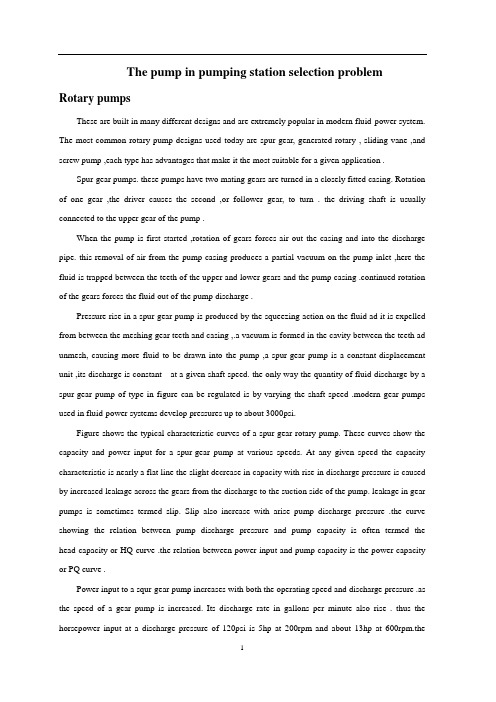
The pump in pumping station selection problem Rotary pumpsThese are built in many different designs and are extremely popular in modern fluid-power system. The most common rotary-pump designs used today are spur-gear, generated-rotary , sliding-vane ,and screw pump ,each type has advantages that make it the most suitable for a given application .Spur-gear pumps. these pumps have two mating gears are turned in a closely fitted casing. Rotation of one gear ,the driver causes the second ,or follower gear, to turn . the driving shaft is usually connected to the upper gear of the pump .When the pump is first started ,rotation of gears forces air out the casing and into the discharge pipe. this removal of air from the pump casing produces a partial vacuum on the pump inlet ,here the fluid is trapped between the teeth of the upper and lower gears and the pump casing .continued rotation of the gears forces the fluid out of the pump discharge .Pressure rise in a spur-gear pump is produced by the squeezing action on the fluid ad it is expelled from between the meshing gear teeth and casing ,.a vacuum is formed in the cavity between the teeth ad unmesh, causing more fluid to be drawn into the pump ,a spur-gear pump is a constant-displacement unit ,its discharge is constant at a given shaft speed. the only way the quantity of fluid discharge by a spur-gear pump of type in figure can be regulated is by varying the shaft speed .modern gear pumps used in fluid-power systems develop pressures up to about 3000psi.Figure shows the typical characteristic curves of a spur-gear rotary pump. These curves show the capacity and power input for a spur-gear pump at various speeds. At any given speed the capacity characteristic is nearly a flat line the slight decrease in capacity with rise in discharge pressure is caused by increased leakage across the gears from the discharge to the suction side of the pump. leakage in gear pumps is sometimes termed slip. Slip also increase with arise pump discharge pressure .the curve showing the relation between pump discharge pressure and pump capacity is often termed the head-capacity or HQ curve .the relation between power input and pump capacity is the power-capacity or PQ curve .Power input to a squr-gear pump increases with both the operating speed and discharge pressure .as the speed of a gear pump is increased. Its discharge rate in gallons per minute also rise . thus the horsepower input at a discharge pressure of 120psi is 5hp at 200rpm and about 13hp at 600rpm.thecorresponding capacities at these speed and pressure are 40 and 95gpm respectively, read on the 120psi ordinate where it crosses the 200-and 600-rpm HQ curves .Figure is based on spur-gear handing a fluid of constant viscosity , as the viscosity of the fluid handle increases (i.e. ,the fluid becomes thicker and has more resistance to flow ),the capacity of a gear pump decreases , thick ,viscous fluids may limit pump capacity t higher speeds because the fluid cannot into the casing rapidly enough fill it completely .figure shows the effect lf increased fluid biscosity on the performance of rotary pump in fluid-power system .at 80-psi discharge pressure the pp has a capacity lf 220gpm when handling fluid of 100SSU viscosity lf 500SSU . the power input to the pump also rises ,as shown by the power characteristics.Capacity lf rotary pump is often expressed in gallons per revolution of the gear or other internal element .if the outlet of a positive-displacement rotary pump is completely closed, the discharge pressure will increase to the point where the pump driving motor stalls or some part of the pump casing or discharge pipe ruptures .because this danger of rupture exists systems are filled with a pressure –relief valve. This relief valve may be built as of the pump or it may be mounted in the discharge piping.Sliding-Vane Pumps,These pumps have a number of vanes which are free to slide into or out of slots in the pup rotor . when the rotor is turned by the pump driver , centrifugal force , springs , or pressurized fluid causes the vanes to move outward in their slots and bear against the inner bore of the pump casing or against a cam ring . as the rotor revolves , fluid flows in between the vanes when they pass the suction port. This fluid is carried around the pump casing until the discharge port is reached. Here the fluid is forced out of the casing and into the discharge pipe.In the sliding-vane pump in Figure the vanes in an oval-shaped bore. Centrifugal force starts the vanes out of their slots when the rotor begins turning. The vanes are held out by pressure which is bled into the cavities behind the vanes from a distributing ring at the end of the vane slots. Suction is through two ports A and AI, placed diametrically opposite each other. Two discharge ports are similarly placed. This arrangement of ports keeps the rotor in hydraulic balance, reliving the bearing of heavy loads. When the rotor turns counterclockwise, fluid from the suction pipe comes into ports A and AI is trapped between the vanes, and is carried around and discharged through ports B and BI. Pumps of this design are built for pressures up to 2500 psi. earlier models required staging to attain pressures approximating those currently available in one stage. Valving , uses to equalize flow and pressure loads as rotor sets areoperated in series to attain high pressures. Speed of rotation is usually limited to less than 2500rpm because of centrifugal forces and subsequent wear at the contact point of vanes against the cam-ring surface..Two vanes may be used in each slot to control the force against the interior of the casing or the cam ring. Dual vanes also provide a tighter seal , reducing the leakage from the discharge side to the suction side of the pump . the opposed inlet and discharge port in this design provide hydraulic balance in the same way as the pump, both these pumps are constant-displacement units.The delivery or capacity of a vane-type pump in gallons per minute cannot be changed without changing the speed of rotation unless a special design is used. Figure shows a variable-capacity sliding-vane pump. It dose not use dual suction and discharge ports. The rotor rums in the pressure-chamber ring, which can be adjusted so that it is off-center to the rotor. As the degree of off-center or eccentricity is changed, a variable volume of fluid is discharged. Figure shows that the vanes create a vacuum so that oil enters through 180 of shaft rotation. Discharge also takes place through 180 of rotation. There is a slight overlapping of the beginning of the fluid intake function and the beginning of the fluid discharge.Figure shows how maximum flow is available at minimum working pressure. As the pressure rises, flow diminishes in a predetermined pattern. As the flow decreases to a minimum valve, the pressure increases to the maximum. The pump delivers only that fluid needed to replace clearance floes resulting from the usual slide fit in circuit components.A relief valve is not essential with a variable-displacement-type pump of this design to protect pumping mechanism. Other conditions within the circuit may dictate the use of a safety or relief valve to prevent localized pressure buildup beyond the usual working levels.For automatic control of the discharge , an adjustable spring-loaded governor is used . this governor is arranged so that the pump discharge acts on a piston or inner surface of the ring whose movement is opposed by the spring . if the pump discharge pressure rises above that for which the by governor spring is set , the spring is compressed. This allows the pressure-chamber ring to move and take a position that is less off center with respect to the rotor. The pump theb delivers less fluid, and the pressure is established at the desired level. The discharge pressure for units of this design varies between 100 and 2500psi.The characteristics of a variable-displacement-pump compensator are shown in figure. Horsepowerinput values also shown so that the power input requirements can be accurately computed. Variable-volume vane pumps are capacity of multiple-pressure levels in a predetermined pattern. Two-pressure pump controls can provide an efficient method of unloading a circuit and still hold sufficient pressure available for pilot circuits.The black area of the graph of figure shows a variable-volume pump maintaining a pressure of 100psi against a closed circuit. Wasted power is the result of pumping oil at 100psi through an unloading or relief valve to maintain a source of positive pilot pressure. Two-pressure –type controls include hydraulic, pilot-operated types and solenoid-controlled, pilot-operated types. The pilot oil obtained from the pump discharge cannot assist the governor spring. Minimum pressure will result. The plus figure shows the solenoid energized so that pilot oil assists compensator spring. The amount of assistance is determined by the small ball and spring, acting as a simple relief valve. This provides the predetermined maximum operating pressure.Another type of two-pressure system employs what is termed a differential unloading governor. It is applied in a high-low or two-pump circuit. The governor automatically, Through pressure sensing, unloads the large volume pump to a minimum deadhead pressure setting. Deadhead pressure refers to a specific pressure level established as resulting action of the variable-displacement-pump control mechanism. The pumping action and the resulting flow at deadhead condition are equal to the leakage in the system and pilot-control flow requirements. No major power movement occurs at this time, even though the hydraulic system may be providing a clamping or holding action while the pump is in deadhead positionThe governor is basically a hydraulically operated, two-pressure control with a differential piston that allows complete unloading when sufficient external pilot pressure is applied to pilot unload port.The minimum deadhead pressure setting is controlled by the main governor spring A. the maximum pressure is controlled by the relief-valve adjustment B. the operating pressure for the governor is generated by the large-volume pump and enters through orifice C.To use this device let us assume that the circuit require a maximum pressure of 1000psi, which will be supplied by a 5-gpm pump. It also needs a large flow (40gpm) at pressure up to 500psi; it continues to 1000pso at the reduced flow rate. A two-pump system with an unloading governor on the 40-gpm pump at 500psi to a minimum pressure setting of 200psi (or another desired value) , which the 5-gpm pump takes the circuit up to1000psi or more.Note in figure that two sources of pilot pressure are required. One ,the 40-gpm pump, provides pressure within the housing so that maximum pressure setting can be obtained. The setting of the spring, plus the pressure within the governor housing, determines the maximum pressure capacity of the 40-gpm pump. The second pilot source is the circuit proper, which will go to 1000psi. this pilot line enters the governor through orifice D and acts on the unloading piston E . the area of piston E is 15 percent greater than the effective area of the relief poppet F. the governor will unload at 500psi and be activated at 15percent below 500psi, or 425psi. By unloading, we mean zero flow output of the 40-gpm pump.As pressure in the circuit increases from zero to 500psi, the pressure within the governor housing also increases until the relief-valve setting is reached, at which time the relief valve cracks open, allowing flow to the tank.The pressure drop in the hosing is a maximum additive value, allowing the pump to deadhead. Meanwhile, the system pressure continues to rise above 700psi, resulting in a greater force on the bottom of piston E than on the top. The piston then completely unseats poppet F, which results in a further pressure drop within the governor horsing to zero pressure because of the full-open position of the relief poppet F. flow entering the housing through orifice is directed to the tank pass the relief poppet without increasing the pressure in housing. The deadhead pressure of the 40-gpm pump then decreases to the lower set value. Thus , at the flow rate to the unloading governor ,the 40gpm pump goes to deadhead. The flow rate to the circuit decreases to 5gpm as the pressure to 1000psi, the 5-gpm pump is also at its deadhead setting, thus only holding system pressure.The 4-gpm pump unloads its volume at 500psi. It requires a system pressure of 600psi to unload the 40-gpm pump to its minimum pressure of 200psi. the 600-psi pilot supply enters through orifice D and acts on the differential piston E. The pumps volume is reduced to zero circuit-flow output at 500psi. The additional 100-psi pilot pressure is required to open poppet F completely and allow the pressure within the housing to decrease to zero.As circuit pressure decreases ,both pumps come back into service in a similar pattern.Axial Piston PumpsIn axial piston pumps of the in-line type, where the cylinders and the drive shaft are parallel ,the reciprocating motion is created by a cam plate, also known as a wobble plate ,tilting plate ,or swash plate .This plate lies in a plane plate that cuts across the center line of the drive shaft and cylinder barrel and does not rotate .In a fixed-displacement pump ,the cam plate will be rigidly mounted in a positionso that it intersects the center line of the cylinder barrel at an angle approximately 25 degrees from perpendicular .Variable-delivery axial piston pumps are designed ,so that the angle that the cam plate makes with a perpendicular to the center line of the cylinder barrel may be varied from zero to 20 or 25 degrees to one or both sides. One end of each piston rod is held in contact with the cam plate as the cylinder block and piston assembly rotates with the drive shaft This causes the pistons to reciprocate within the cylinders .The length of the piston stroke is proportional to the angle that the cam plate is set from perpendicular to the center line of the cylinder barrel .A variation of axial piston pump is the bent-axis type is shown in 1-1 .This type does not have a tilting cam plate as the in-line pump does .Instead ,the cylinder block axial is varied from the drive shaft axis .The ends of the connecting rods are retained in sockets on a disc that turns with the drive shaft .The cylinder block is turned with the drive shaft by a universal joint assembly at the intersection of the drive shaft and the cylinder block shaft ,In order to vary the pump displacement ,the cylinder block shaft and valve plate are mounted in a yoke and the entire assembly is swung in an are around a pair of mounting pintles attacked to the pump housing .Figure 1-1 Bent –axis axial piston pumpThe pumping action of the axial piston pump is made possible by a universal joint or link .Figure1-2is a series of drawings that illustrates how the universal joint is used in the operation of this pump .First ,a rocker arm is installed on a horizontal shaft .(See fig 1-1view A )The arm is joined to the shaft by a pin so that it can be swung back and forth ,as indicated in view B。
- 1、下载文档前请自行甄别文档内容的完整性,平台不提供额外的编辑、内容补充、找答案等附加服务。
- 2、"仅部分预览"的文档,不可在线预览部分如存在完整性等问题,可反馈申请退款(可完整预览的文档不适用该条件!)。
- 3、如文档侵犯您的权益,请联系客服反馈,我们会尽快为您处理(人工客服工作时间:9:00-18:30)。
利用神经网络预测轴向柱塞泵的性能Mansour A Karkoub a, Osama E Gad a, Mahmoud G Rabie ba——就读于科威特的科威特大学工程与石油学院b——就读于埃及开罗的军事科技大学摘要本文推导了应用于轴向柱塞泵(斜轴式)的神经网络模型.该模型采用的数据是由一个实验装置获得的.这个正在进行的研究的目的是降低柱塞泵在高压下工作时的能量损耗。
然而,在最初我们要做一些研究来预测当前所设计的泵的响应。
神经网络模型具有前反馈的结构,并在测验过程中使用Levenberg-Marquardt 优化技术.该模型能够准确地预测柱塞泵的动态响应.1、简介可变排量轴向柱塞泵是在流体动力系统中经常要用到的重要设备,如液压动力供应控制和静液压传动驱动器的控制。
本装置具有变量机制和功率-重量比特性,使其最适合于高功率电平的控制.所设计的这种轴向柱塞泵拥有可靠性和简便的特点,然而其最重要的特征是可以变量输出。
人们在轴向柱塞泵领域已经做了很多研究,但是本文将只论述一下少数几人所做的贡献. Kaliafetis和Costopoulos[5]用调压器研究了轴向柱塞变量泵的静态和动态特性。
所提出的模型的精确度依赖于制造商提供的动态运行曲线等数据。
他们得出结论,运行条件对泵的动态行为是非常关键的,而泵的动态行为可以通过减小压力设定值进行改善.Harris等人[4]模拟和测量了轴向柱塞泵的缸体压力和进油流量脉动。
Kiyoshi和Masakasu[7]研究了斜盘式变量输送的轴向柱塞泵在运行时刻的实验上和理论上的静态和动态特性。
并提出了一种新的方法来预测泵在运行过程中的响应。
也对研究泵特性的新方法的有效性进行了实验验证,实验中使用了一个有宽、短而深的凹槽的配流盘。
Edge和Darling[2]研究了液压轴向柱塞泵的缸体压力和流量.这个得出的模型经过了实验检验.对于配流盘、缸体上设计的退刀槽和泵的流量脉动对泵特性的影响都进行了验证.人们已证实了一种可替代的建模技术-—神经网络(NN)能取得良好的效果,特别是对于高度非线性的系统。
这种技术是模仿人脑获取信息的功能。
Karkoub 和Elkamel[6]用神经网络模型预测了一个长方形的气压轴承的压力分布。
所设计的这种模型在预测压力分布和承载能力方面比其他可用的工具更加精确.Gharbi 等人[3]利用神经网络预测了突破采油。
其表现远远优于常见的回归模型或有限差分法.李等人[8]用神经网络模型NNS和鲍威尔优化技术对单链路和双链路的倒立摆进行了建模和控制。
研究者们取得了理想的结果.Panda等人[9]应用NNS在普拉德霍湾油田对流体接触进行了建模。
所得到的模型预测的目标油井中的流量分配比传统的以回归为基础的技术更准确。
Aoyama等人[1]已经推导出一个神经网络模型来预测非最小相系统的响应。
所开发出的的模型被应用于Van de Vuss 反应器和连续搅拌式生物反应器,所得到的结果是令人满意的。
本文研究利用神经网络解决轴向柱塞泵(斜轴式)在一定的供油压力下的建模。
本文首先会描述用于收集实验数据的实验装置,然后将会简要介绍神经网络建模程序。
2、实验装置实验数据是从这个将在本节中进行讨论的实验装置上得到的。
该装置的主要组成部分是轴向柱塞泵。
在下面的章节中,我们将描述泵的工作原理,然后描述如何收集实验数据。
2。
1、斜轴式轴向柱塞泵示意图2显示出了在实验中使用的轴向柱塞泵的基本组件,而此泵的控制单元如图3所示。
该泵由两个主要部分组成.第一部分是旋转组,其中包括驱动轴(31)、柱塞(32)、缸体(33)和配流盘(34).七个柱塞安装在一个位于前表面的球形组件上,并且他们同时动作使缸体旋转。
缸体通过弹簧(35)推压控制区域的配流盘。
在运行过程中,带有柱塞的配流盘和缸体可以在一个球形的滑动表面(36)上移动。
配流盘采用了在进油口和出油口的前缘和后缘都带有半圆形凹槽的双向配流盘。
第二部分是泵的控制部分,其中包含了控制柱塞(37)、控制元件(38、39和40)、调节弹簧(41)和控制弹簧(42)和(43)。
两个主要部分是用调节销(44)连接在一起的.体积为V的泵出口腔与体积为V1和V2的控制腔通过孔(45)和(46)分别连通。
控制柱塞连通开口孔(47)、该开口孔的大小是由活塞(40)(参照图2和图3)控制的。
当操作压力P超过了弹簧(41)的预设值,控制元件(38、39和40)就会推压弹簧.与此同时,液压油通过节流孔(45)和(46)从泵的出口流出。
在体积为V1的腔体内的高压油就从开口孔(47)流到了控制柱塞(37)的大端面上.如果作用在控制柱塞上的压力大于弹簧力,控制柱塞(37)就会移动,直到液压力和机械力恢复平衡.缸体、柱塞和配流盘在球形滑动表面(36)以相反的方向移动,以减少旋转角度αmax〈α<αmax。
此运动会导致泵的流速降低。
2。
2、数据测量装置利用神经网络设计的模型必须要使用从上述系统获得的一些实际数据进行检验.检验的过程对于神经网络了解它试图预测的模型是必要的。
数据是从图1所示的实验装置中收集的。
此数据是通过测量图2所示的轴向柱塞泵的稳态和瞬态响应获得的.图1 实验装置的照片图 2 斜轴式轴向柱塞泵的示意图图3 柱塞泵的控制单元的示意图实验研究是在如图1所示的测试平台上进行的,液压回路图如图4所示。
试验泵的进油管和出油管分别与吸油管和高流量计的端口(24)和(25)直接连接在一起。
试验泵(16)是由一个高功率的可控速度的液压马达(13)驱动的。
液压回路的工作过程如下:油从油箱(1)流入增压泵(4)的进油口。
减压阀(7)是用来保护增压泵回路以避免其压力过高。
增压泵溢出的液压油通过一个单向阀(6)流入主泵(3)的吸油和供油线路.减压阀(8)是用于保护主泵回路防止压力过高。
从主泵流出的液压油通过用于控制主泵流向的方向控制阀(9)和(10)流入主驱动马达回路(12)。
试验泵的流速由数字式的流量计(20)显示。
试验泵的从动轴的转速是由转速计(15)测量的,可以通过改变电动机(5)的速度来控制从动轴的速度.在操作过程中工作油的温度要保持在50±5℃的范围内.图4 液压系统示意图在稳态测量期间,当开关阀(30)完全关闭时供给压力P的变化是由控制阀(29)调节的。
压力计(23)用来测量进油管路中的油压,数字压力计(21)测量出油线路中的油压。
减压阀(28)是用来保护试验泵回路以防过载.而在瞬态测量期间,阀(30)是完全打开的而阀(29)是完全关闭的。
2。
3、泵的稳态响应的测量所研究的泵的稳态性能的实验测定是通过测量不同的供给压力P下的泵的排出流量Qp来进行的.试验泵的参数如表1所示.供给压力P是由节流阀(29)控制的,其压力值由数字压力计(21)测得。
相应的泵排量Qp是由数字流量计(20)测量的.测量时预设压力相同而泵的转速不同,泵的转速分别为550、800和1000 rpm。
泵的排量Qp也是在不同的预设压力值下测量的.测量值如图7和图8所示。
参数描述数值A控制柱塞的大端面0。
000531 m2cA柱塞面积0。
000531 m2pA控制元件(38)的面积0。
0000246 m2ppA控制柱塞的小端面面积0.0000785 m2sV泵输油管道体积2。
6×10⁻³ m3V第一控制腔的体积8。
2×10⁻⁶ m31V第二控制腔的体积1。
7×10⁻⁷ m32V第三控制腔的体积 1.6×10⁻⁵ m33α缸体最小倾斜角4°minα缸体最大倾斜角23°max2。
4 泵的瞬态响应的测量图2所示的待研究的泵的瞬态响应的实验测定是通过测量不同控制腔的工作压力来进行的.在泵体的不同位置安装着三个电控压力传感器,该泵体是和体积分别为V1、V2和V3的控制腔直接连接在一起的,如图3所示。
另一个压力传感器被安装在泵出口体积V的管路上来测量供给压力P。
这些传感器都是压阻式的,可以测量的压力范围为0。
1到400bar之间.每个传感的输入电压为10〜30V,而输出电压是在0到5V之间.这些传感器是用来测量控制压力P1、P2、P3和P (参照图3)的。
压力信号的时域图谱是使用PC机和数据采集板采集的。
转换时间为12μs的12位逐次逼近转换器的数据采集板能实现70 kHz的最大吞吐率.泵的出口管路上安装有节流口大小固定的节流阀(18)和方向控制阀DCV(17)(参照图1和图4).这些阀可以使泵的出口管路的压力P快速变化。
当DCV的电磁阀通电时,阀门迅速关闭,泵的排出流量Qp就被迫流经节流阀.这样设置试验台就能使电磁阀中的电流能触发数据采集系统,从而拾取瞬间变化的压力P1、P2、P3和P的值.这些数据的测量是在泵的转速为550、800和1000 rpm的情况下进行。
测量结果如图9、图10和图11所示.3、神经网络在本文中,用于预测斜轴式轴向柱塞泵的动作的装置是一个被称为神经网络的计算工具。
这些网络都只是一些相互联接在一起的被称为神经元的元素。
这些神经元或处理单元是精心挑选的线性或非线性函数,这些函数可以处理任何应用输入以得到其输出。
神经元的输入是外部输入的加权总和,或是紧挨着它的上一个神经元的输出。
一个小的加权施加到神经元的输出上就会使接下来的神经元不能处理其输入。
人们就能以这种方式建立每个模式或输入的具体路线图。
这种类型的模型就能使神经网络能够捕捉通常未能被普通建模技术发现的非线性信号。
一个特定的神经元的输出是关于三个主要因子:加权输入、该神经元的偏压和传递函数(参见图5)的函数。
任何神经元的输出都可按下式计算:a=f(x+β)其中传递函数f可以选自一组现成可用的函数.在我们的研究中所选用的是S型函数:该函数以能得到理想的结果而著名,特别是对于给定的输入其输出是已知的情况。
图5 单个神经元的示意图任何网络通常都可划分为各个子网或我们通常所称呼的层。
每个网络包含两个基本层即输入层和输出层,而且如果任务需要就会有一个或多个隐藏层。
图6显示出了一种典型的前馈式结构的神经网络。
输出层的输出是网络中所有神经元的组合效果的结果。
图6 多层、前馈式神经网络的示意图3.1、测验设计一个神经网络至少需要四个主要步骤:(1)确定网络层的层数:(2)确定神经元数量:(3)确定传递函数的类型:(4)确定一个能描述系统行为实验数据组。
测验过程非常耗费时间但对于网络的成功非常关键。
测验中要应用几项技术,其中有一项是势能的反向传播.每一个神经元的每一个输入的权重都是从输出层和工作反馈开始连续变化更新的。
在此过程中,要使目标函数最小化,而目标函数通常是误差的平方和函数。
文献中应用到了几项优化技术,包括鲍威尔算法和Levenberg—Marquardt算法。