CPM系统构成与功能介绍
康复cpm的名词解释
康复cpm的名词解释康复CPM,全称连续被动运动,是康复医学领域常用的一种物理治疗方法。
它通过特殊的机械装置,帮助患者进行连续被动运动,促进关节恢复功能,改善肌肉骨骼系统的运动能力。
本文将从康复CPM的原理、应用范围、优势与限制等方面进行详细解释。
一. 康复CPM的原理康复CPM是通过特殊的机械装置帮助患者进行连续被动运动,从而促进关节的恢复和康复。
其原理基于连续被动运动对关节和肌肉的生理作用。
连续被动运动可以帮助患者迅速恢复关节的活动范围,预防和减少关节僵硬。
在康复过程中,一些病患由于疼痛或手术后无法主动活动,而康复CPM能够更好地达到关节活动的目标。
此外,连续被动运动还能够帮助改善关节周围肌肉的力量,增强肌肉的协调性和稳定性。
二. 康复CPM的应用范围康复CPM广泛应用于关节创伤、韧带损伤、关节置换手术等康复治疗中。
例如,对于关节置换手术后的患者,康复CPM能够有效帮助他们快速恢复关节的功能。
对于肩袖损伤的患者,康复CPM可以减轻疼痛,并帮助肩关节恢复正常的运动范围。
除了关节创伤和手术后的康复治疗,康复CPM还可用于对付肩周炎、尺骨骨折、髂腰肌综合征等病症。
对于这些患者,康复CPM的应用可以加快康复进程,简化治疗程序。
三. 康复CPM的优势康复CPM相较于传统物理治疗方法有如下优势:1. 有效性:康复CPM通过机械设备提供的连续被动运动,能够更加精准地治疗特定关节或骨骼,有效促进康复进程。
2. 安全性:康复CPM使用的是机械装置,由专业医护人员操作,比较安全可靠。
并且,康复CPM的运动范围和速度也能根据患者的情况进行调整,确保治疗的安全性。
3. 个性化:康复CPM可以根据患者的实际情况进行调整,包括运动范围、速度、时间等。
这使得康复CPM更加符合患者的个体差异和治疗需求。
四. 康复CPM的限制康复CPM虽然有着众多优势,但也存在一些限制:1. 成本问题:康复CPM设备相对比较昂贵,对一些医疗机构来说,购买和维护这些设备的成本较高,限制了其在临床中的应用范围。
cpm持续关节被动运动的名词解释
cpm持续关节被动运动的名词解释
摘要:
1.持续关节被动运动(CPM)的定义
2.CPM 的作用和应用范围
3.CPM 的优点和注意事项
4.CPM 在临床治疗中的应用案例
正文:
持续关节被动运动(Continuous Passive Motion,简称CPM)是一种在特定范围内,通过专用设备使关节进行持续、缓慢、被动运动的技术。
CPM 主要应用于关节损伤、手术后康复以及肌肉骨骼疾病的治疗中,旨在维持关节活动度,促进关节液流动,改善局部血液循环,加速康复进程。
CPM 的作用和应用范围广泛。
对于关节损伤或手术后的患者,CPM 可以减轻疼痛,缓解肿胀,防止关节僵硬,并有助于恢复关节活动能力。
此外,CPM 在肌肉骨骼疾病的治疗中也发挥着重要作用,如颈椎病、腰椎病、肩周炎等。
CPM 具有诸多优点,包括设备操作简便、患者舒适度高、治疗效果明显等。
然而,在实际应用中,也应注意一些事项。
例如,患者在佩戴CPM 设备时,应保持舒适的体位,避免过度紧张;治疗过程中,应注意监测患者的生理反应,如疼痛、肿胀等,一旦出现异常情况,应立即停止治疗。
在临床治疗中,CPM 的应用案例丰富。
例如,在膝关节置换术后的康复过程中,患者可以使用CPM 设备进行膝关节的持续被动运动,以保持关节活
动度,提高康复效果。
再如,对于肩关节损伤的患者,CPM 设备可以帮助患者在无痛的情况下进行肩关节的被动运动,从而缓解疼痛,改善关节活动能力。
总之,持续关节被动运动(CPM)作为一种有效的治疗手段,在关节损伤、手术后康复以及肌肉骨骼疾病的治疗中发挥着重要作用。
CPM应用讲解ppt医学课件
Rabbits with full thickness cartilage defects divided into three groups: 兔子全层软骨损伤分三组(I,II,III):
➢ Immobilization with cast ➢ 石膏固定组
➢ Intermittent Active Motion (Cage activity) ➢ 间歇性主动运动组 ➢ CPM regimen:Treatment initiated immediately
1980年,KINETEC施乐辉CPM开始大规模生产,经历 30年不断地发展和改进,已经成为唯一能够提供全身 六大关节的CPM厂家,技术和品质皆为业内典范。
Enforced强制限制 Uninterrupted不间断 Prolonged长期的
传统康复理念 Immobilization
固定
Inhibit the circulation of Synovial Fluid 制约滑液的循环
运动方式必须完全符合生理曲线,否则病人将回十分
不适,而且导致关节损伤。
Non-anatomical 不符合生理曲线
Semi-anatomical 半符合生理曲线
Anatomical 符合生理曲线
ANATOMY & MOVEMENTS 解剖和运动
There are some basic things to know…
“Functional activity should only be temporarily repressed. The intermediate stage is to partially
exercise the function.”
Bonnet: Traité de Therapeutique des Maladies articulaires. Paris 1853
cpm概述及使用流程
1.使用时动作轻柔。
2.及时收ห้องสมุดไป่ตู้,放置固定地点保存。
3.发现污垢及时清理干净。
4.如果使用过冲中发现异常及时送专业维修部门进行维修。
(六)评估要点
1.评估患者精神状况、配合程度、伤口情况。
2.评估患者有无深静脉血栓。
3.评估患者病情变化。
(七)宣教要点
1.告知患者使用CPM机进行功能锻炼的作用及意义。
患者的安全是护理工作的首要任务
8
用75%酒精擦拭后整理主机、电源线,妥善保存
正确的养护可有效地延长CPM机的使用寿命
注意事项:
1.使用过程中如有伤口渗血、疼痛等不良反应时要及时停止使用并及时处理。
2.放置负压引流的患者,应用CPM机时应关闭负压引流管,停机时再放开,防止负压作用使引流管内液体回流而造成感染发生。
合适的机杆长度让患者感到舒适,提高治疗效果
5
CPM机运转正常后,将呼叫器放于患者可及之处,告知患者如有不适及时通知护士,整理床单后方可离开
及时发现并解决问题
6
护士返回治疗室,洗手,做好记录,再次核对医嘱
严格执行核对制度
7
30分钟后,护士至患者床旁,关闭开关并拔掉电源,将CPM机取下。给予患者安置舒适体位,并整理床单
CPM机概述
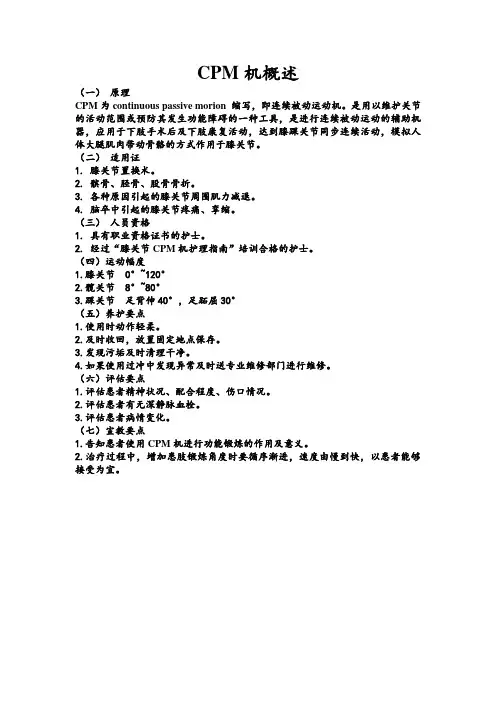
(一)原理
CPM为continuous passive morion缩写,即连续被动运动机。是用以维护关节的活动范围或预防其发生功能障碍的一种工具,是进行连续被动运动的辅助机器,应用于下肢手术后及下肢康复活动,达到膝踝关节同步连续活动,模拟人体大腿肌肉带动骨骼的方式作用于膝关节。
(二)适用证
2.治疗过程中,增加患肢锻炼角度时要循序渐进,速度由慢到快,以患者能够接受为宜。
cpm机收费编码
CPM机收费编码1. 简介CPM机(Charge Processing Machine)是一种用于处理收费的机器,它可以自动计算和收取各种费用,例如停车费、公共交通费、门票等。
CPM机收费编码是指在CPM机中使用的一套编号系统,用于标识不同的收费项目和金额。
2. CPM机的功能CPM机是现代社会中广泛应用的一种设备,它具有以下主要功能:2.1 收费计算和结算CPM机可以根据预设的收费标准和编码,自动计算不同项目的费用,并生成详细的账单。
用户只需输入相应的编码或选择对应的项目,即可快速完成支付。
2.2 票据打印CPM机还可以打印出相关的票据,包括发票、收据等。
这些票据可以作为用户付款凭证,也可用于后续报销或记录。
2.3 数据管理与报表生成CPM机能够存储用户支付信息,并生成各类统计数据和报表。
这些数据可以帮助管理者了解收入情况、分析用户消费习惯等,并为决策提供依据。
3. CPM机收费编码系统为了实现对不同项目和金额进行准确计算和识别,CPM机采用了一套编码系统。
这套编码系统通常由数字、字母或符号组成,用于标识不同项目和金额。
下面是一个示例:编码项目金额(单位:元)A1 停车费10B2 公交车票 2C3 游乐场门票50在使用CPM机时,用户只需输入相应的编码,即可完成支付。
4. CPM机收费编码的优势CPM机收费编码系统具有以下优势:4.1 快速高效通过使用收费编码,用户无需逐一输入项目名称和金额,只需输入简单的编码即可完成支付。
这大大提高了收费效率,缩短了用户等待时间。
4.2 准确无误收费编码系统可以减少人为错误的发生。
相比于手动输入项目名称和金额,使用统一的编码可以避免因输入错误而导致的计算错误或费用混淆。
4.3 灵活性强CPM机收费编码系统可以根据实际需要进行扩展和调整。
新的收费项目和金额可以很容易地添加到现有的编码系统中,而无需对机器进行重大改动。
5. 使用CPM机的场景CPM机广泛应用于各种需要收费的场景,例如:5.1 停车场停车场是CPM机最常见的应用场景之一。
Rolls-Royce 连续气动压力监测系统 - CPM 系统说明书
Cylinder Pressure Monitoring (CPM) For peak performance and improved reliabilityOptimizing equipment reliability and lifecycle costs are key requirements for operating a power plant profitably. That’s why, in addition to developing new products that meet improved performance targets, we also focus on optimizing the performance of our legacy equipment operating in the field-generator sets that are built to run for decades. For you that means continuous improvements, and genuine confidence that your equipment will always achieve its full potential.Available for all medium speed gas engines from Rolls-Royce, the continuous cylinder pressure monitoring (CPM) system stabilizes engine performance, significantly improving its reliability while also protecting it from excessive stress. The Otto-cycle combustion process used in medium speed gas engines allows for minor variance in firing pressures without any noticeable consequences for the operation. However, optimizing the engine’s combustion pressure levels with CPM results in exceptionally smooth and stable operation. This is achieved through continuous alignment of the combustion pressures thanks to an automatic monitoring and adjustment process.A wide range of real-time combustion data iscontinuously monitored by sensors installed in each combustion chamber. This data is analysed and used as a basis for optimization, including adjustment of the ignition angle, to ensure automatic alignment of firing pressures across all cylinders. As a result,Improve equipment reliability by aligning cylinder pressures Protect your equipment and reducelifecycle costsequipment efficiency and fuel consumption are optimized. Operational experience with CPM has shown a reduction in fuel consumption of up to 2% depending on the current tuning of the engine. Smoother operation increases overall equipment safety and component life. And protecting it from excessive vibrations due to misfiring, knocking and mechanical or thermal overload helps improve its reliability while reducing unscheduled stops.As a result of the stabilized combustion pressures, emissions are contained at the design level. Emissions and efficiency can be further optimized with an automatic NOx control upgrade (if not already fitted) available for gas engines.In addition to the peak firing pressure control, CPM also includes the following protection and monitoring functions:• High pressure detection • Knock detection • Misfire detection• Detection of thermal overload in cylinders • Condition monitoring of the cylindersAll the above functions are shown on the CPM touch screen with an indication of the affected cylinder(s).An intelligent system for smootherengine operationApplicable installationsOperation and maintenanceAll CPM system alarms are displayed on the CPM touch screen, and can also be integrated in the plant’s SCADA (Supervisory Control And Data Acquisition).As the CPM is an automated system, special attention is not necessary to keep it functioning properly. To ensure prompt detection of performance issues or other irregularities requiring attention, a simple daily monitoring routine is all that’s required.The intelligent system simplifies daily operation and provides increased visibility into the condition of the systems combustion components, helping you time service activities appropriately and avoid unscheduled stops.By measuring all cylinder pressures simultaneously, CPM enables the engine tuning process to be completed more quickly after service, reducing plant downtime significantly.In addition to normal spread variance in firing pressure, increased instability comes from several other factors. Over time, minor drifting of gas valves, spark plugs, pre-chamber valves and other combustion components may occur.Additionally, the manual demands of traditional measurement of cylinder pressure, when combined with any deviation from original factory settings, will affect the engine’s performance and stability.Manual ignition tuning is generally done after every main overhaul, whereas CPM continuously makes the adjustments automatically, in parallel on all cylinders, ensuring a more accurate result.© Bergen Engines AS 2017The information in this document is the property of Bergen Engines AS and may not be copied, or communicated to a third party, or used, for any purpose other than for which it is supplied without the expressed written consent of Bergen Engines AS.Bergen Engines ASA Rolls-Royce Power Systems CompanyPO Box 329 Sentrum, N-5804 Bergen, Norway /bergen ******************************。
中心-边缘模型(cpm)研究述评
中心-边缘模型(cpm)研究述评中心-边缘模型(CPM)是一种用于描述复杂网络中节点特异性的模型。
该模型旨在探索网络结构和节点属性之间的关系,并揭示在一个网络中哪些节点是中心节点,哪些是边缘节点。
该模型在社交网络、生物网络和技术网络等领域广泛应用,成为了网络分析领域中的重要工具。
一、模型原理CPM是基于度中心性度量的网络模型。
度中心性是指网络中某个节点直接连接的节点数量。
在CPM中,节点的度中心性被看作是一个节点在网络中的中心度量。
然而,CPM并不仅仅考虑节点本身的度中心性,也考虑节点周围节点的度中心性。
因此,CPM可以描述节点之间的相互关系,并将它们分为中心节点和边缘节点。
二、模型应用CPM在社交网络分析研究中广泛应用。
研究表明,社交网络中的中心节点往往具有比较大的度中心性和介数中心性,是社交网络中最受欢迎和最有影响力的节点。
因此,CPM可以用于帮助人们理解社交网络中节点的重要性和影响力。
除了在社交网络中的应用,CPM还被应用在生物网络和技术网络中。
例如,在生物网络中,CPM可以用于揭示哪些蛋白质在细胞中具有很重要的功能,并且起着关键的作用。
在技术网络中,CPM可以用于优化通信网络中的节点布局,从而提高通信效率和网络性能。
三、模型结论CPM模型可以揭示网络中节点之间的相互关系,并把节点分为中心节点和边缘节点。
这一结论可以广泛应用于生物网络、技术网络和社交网络等领域。
因此,CPM模型是一种重要的工具,可以帮助人们更好地理解网络结构和节点属性之间的关系。
同时,CPM模型也有一些局限性,例如该模型不能考虑节点的其他属性,如节点大小、颜色等。
因此,在研究网络数据时,需要根据实际情况选择最合适的模型。
综上,CPM模型是一种重要的网络分析工具,广泛应用于社交网络、生物网络和技术网络等领域。
它可以帮助人们更好地了解网络结构和节点属性之间的关系,揭示中心节点和边缘节点。
我们相信,在未来的研究中,CPM模型将继续发挥作用,并成为网络分析领域中的重要组成部分。
CPM机应用讲解
增加关节软骨的营养和代谢活动
成人关节软骨的营养来自滑膜液,并依赖于
健康的滑膜 关节的充分体液循环
随着关节活动,促进滑液向关节软骨的浸透和 扩散,加速滑膜的分泌和吸收,改善软骨细胞 的新陈代谢,利于软骨组织的再生和功能活动, 清除关节内有害物质和坏死组织
加速关节软骨和关节周围组织 (韧带、肌腱)的损伤修复
6、全膝关节置换病人术后第2天或切口引流管拔 管后第1天即可开始通过CPM机做关节被动屈伸 运动,在应用“膝关节“方式情况下,必须将 传感器线缆和插座有效连接,起始伸直角度从 0°,屈曲角度从20°-30°开始,以后根据病 人具体情况每天可酌情增加5°-10°,术后一 周内膝关节屈曲达90°,二周屈曲达120°。
CPM机应用讲解
概要
连续被动活动(CPM),是一种新的生物 学概念,即在连续被动活动作用下,加 速关节软骨及周围的韧带和肌腱的愈合 和再生。
起源
20世纪70年代初,加拿大骨科医师Salter RB提出CPM即滑膜关节持续被动活动理 论
CPM理论提出(一)
在此理论提出之前,绝大多数人,主张病损肢 体应以制动为主,以利于修复
禁忌症
开放性骨折污染严重的,术后感染没有得到控制的, 不可使用CPM机。
术后必须有坚强的内固定。临床上关节周围骨折严重 不能坚强内固定者、软组织损伤重者或骨折合并膝关 节韧带损伤修复者等均不宜早期CPM锻练。
术后发现有下肢深静脉血栓形成的,为了防止肺栓塞 的发生,不可使用CPM机。
简单故障排除和养护
6、调整“控制力矩“:力矩”大“表示机器以电机 100%输出功率控制工作;力矩”中“表示机器以电机 65%输出功率控制工作;力矩”小“表示机器以电机 35%输出功率控制工作、超过设定的力矩控制,则机 器将自动反向运行,以保持患者肢体。
cpm管理体系
CPM管理体系简介
CPM(Critical Path Method)管理体系是一种用于管理和控制项目进度的方法。
CPM方法将项目分解为一系列任务,并确定每个任务的持续时间和关系,以确定关键路径和关键活动。
通过对关键路径和关键活动进行管理和控制,可以有效地控制项目进度和风险。
CPM管理体系包括以下几个主要步骤:
1.定义项目目标和范围:明确项目的目标、可交付成果和约束条件,以及项目的工作范围和时间范围。
2.制定项目计划:将项目分解为一系列任务,确定每个任务的持续时间和关系,并制定详细的项目计划。
3.确定关键路径和关键活动:确定项目中的关键路径和关键活动,以及它们对项目进度和质量的影响
4.控制项目进度和风险:通过对关键路径和关键活动进行管理和控制,控制项目进度和风险,确保项目按时交付、质量符合要求。
5.进行项目监督和评估:定期监督和评估项目的进度和质量,及时发现和解决问题,确保项目顺利完成。
CPM管理体系是一种系统化的项目管理方法,能够帮助项目管理人员有效地控制项目进度和风险,提高项目成功率。
它已经被广泛应用于各种类型的项目管理,包括建筑工程、IT项目、制造业等。
Continuous Pressure Monitor (CPM)系统安装和配置说明说明书
HardwareWe installed a total of 23 FOPSs on all the power cylinders of the three engines. These unique sensors are immune to electrical noise and can transmit data over great distances. The fiber-optic cables ran between the engine room and the test trailer where the signal conditioning and data acquisition system were located.We equipped each engine with amagnetic pick-up mounted at the flywheel to sense the passage of a pin or bolt corresponding to TDC of Cylinder 1.The magnetic pick-up from each engine was connected directly to the DAQ board.For the Continuous Pressure Monitor (CPM) system, we chose theAT-MIO-64E-3 multifunction DAQboard, based on the price and high channel count. We installed it in an ISA slot in the docking-station of a Compaq 486 laptop running Windows 95. The client had specified the laptop/docking-station configuration to meet the requirements of the mobile test trailer.The CPM acquired data from thesensors, reduced it, and transmitted it to the station data highway via RS-232. We alsoContinuous Monitoring of Internal-Combustion Engines Using LabVIEWby Alden Cramer and Greg Beshouri,Advanced Engine Technologies CorporationThe Challenge:Continuously monitoring the performance of large internal-combustion engines at gas transmission pipeline compressor stations.The Solution:Developing aPC-based system using a DAQ board and serial port interfaces controlled by LabVIEW.IntroductionSince 1995, vendors have sold fiber-optic pressure sensors (FOPSs) for continuously measuring combustion pressure in large bore internal-combustion engines in the 2,000 to 25,000 brake horsepower range.These sensors provide the natural gas transmission industry a unique opportu-nity to significantly enhance on-line monitoring and diagnostics of their gas-powered compressor engines. Moreover,when we integrate FOPS data with engine operational data, we greatly enhance closed-loop engine control and emissions monitoring.Integration of engine combustionpressure data into overall engine monitor-ing and control systems, however,presents several challenging tasks.Pressure data from each cylinder must be continuously acquired at a rate of 2 kHz,phase referenced to top dead center (TDC), and then reduced to extract key pressure values. Results must then be transmitted to the engine distributed-process controller and/or the client’s data highway using a serial communications protocol such as Modbus. Finally, the combustion pressure data must be made available at the engine catwalk for“real-time” combustion pressure analysis and diagnostics.System DevelopmentAdvanced Engine TechnologiesCorporation (AETC) teamed with a major natural gas pipeline company to develop and operate a “Beta” Continuous Pressure Monitor/Fast Balance system forapplication at a compressor station with three engines. This development required •Implementation of a 32-channel data acquisition system using the National Instruments AT-MIO-64E-3 board •Development of LabVIEW applications for system configuration, transducer calibration, and data reduction•Development and implementation of digital communication protocols for data exchange with the client datahighway, individual distributed-process controllers, and the operator interface •Development of a LabVIEW graphical user interfaceBecause the client could offer AETC only four months to design, develop, test,and implement the system, we chose to leverage off our experience with National Instruments data acquisition (DAQ) hard-ware and LabVIEW. We completed the final system on time and within budget.W e chose to leverage off our experi-ence with National Instruments data acquisition (DAQ) hardware and LabVIEW. The final system wascompleted on time and within budget.Automated Tests LabVIEW ™s DAQsSerial CommunicationBlock Diagram of CPM/FB Systemmade the data available to connection points in the engine room via RS-485, for transfer to the portable Fast Balance (FB)computer. A National Instruments AT-4852-port board was used to eliminate the need for RS-232 to RS-485 conversion.We used a ruggedized handheld Texas Micro Hardbody 486 as the FB computer,which needed to be portable so the operator could view the effects of mechanical adjustments directly.SoftwareContinuous Pressure MonitorAlthough we based the CPM application on robust field test software developed by AETC, we found it lacking for continuous monitoring because it was written for triggered data acquisition. In shifting from triggered to continuous data acquisition,we knew that simply acquiring data and then reducing and transmitting the data would result in poor performance.As recommended in an article inLabVIEW Technical Resource , we used the Wait for Occurrence function to free up the CPU for data reduction and transmission.It worked surprisingly well, even on the 66 MHz 486 laptop!Our previous work with FOPS engine analysis greatly simplified the datareduction task. We had developed FOPS data reduction programs for selecting specific points in the combustion cycle.The points of interest were defined as: •Peak Pressure•Location of Peak Pressure re TDC •Standard Deviation of Peak Pressure •Pressure at 10 deg before TDC •Pressure at 180 deg before TDCFor the data transmission program, we reused code from previous projects with a wide variety of engine controllers using the Modbus protocol. We used existingLabVIEW subroutines to write data from the CPM to the Bristol 3330 DataConcentrator as a Modbus master. We used the same LabVIEW subroutines to write the data to the FB computer via RS-485.offers two primary savings over weekly manual balance checks:1.It eliminates unnecessary testing when the engine is running properly.2.It flags potentially degenerativeconditions immediately so the plant can take corrective action.Based on the Item 1 alone, the CPM/FB cost could probably be amortized in five years. But also, in engine applications where emissions must be logged and reported, we can use the combustion pressure data acquired by the CPM/FB to calculate engine emissions extremely accurately at a fraction of the cost of traditional exhaust gas analyzers.1For more information, contact Alden Cramer or Greg Beshouri, Advanced EngineTechnologies Corp., 2100 Embarcadero, Suite 201, Berkeley, CA, 94710, tel (510) 437-8990,fax(510)437-1249,*********************U.S. Corporate Headquarters •Tel:(512)794-0100•Fax:(512)683-8411•****************•Branch Offices:Australia 03 9879 5166 • Austria ***********•Belgium 02 757 00 20 • Brazil 000811 781 0559 • Canada 905 785 0085 • Denmark 45 76 26 00 • Finland 09 725 72511France 01 48 14 24 24 • Germany 089 741 31 30 • Hong Kong 2645 3186 • Israel 03 6120092 • Italy 02 413091 • Japan 03 5472 2970 • Korea 02 596 7456 • Mexico 001 800 010 0793Netherlands 0348 433466 • Norway 32 84 84 00 • Singapore 2265886 • Spain 91 640 0085 • Sweden 08 730 49 70 • Switzerland 056 200 51 51 • Taiwan 02 2377 1200 • U.K. 01635 523545© Copyright 1998 National Instruments Corporation. All rights reserved. Product and company names listed are trademarks or trade names of their respective companies. 361030A-02 070698Fast BalanceTo achieve the FB goal of providing the operator an intuitive, simple interface, we manipulated standard LabVIEW controls and indicators for the desired look and feel. A bar graph shows directly which cylinder is running high or low from the average. As one user commented, “It’s simple. Big red bars are bad.” We also display numerical values for each cylinder and engine operating parameters from the data highway. The alarms will flash red when the delta value for any cylinder crosses the selected limit line. This feature alerts the operator to a misfire,even when viewing the Peak Pressure display.Benefits of CPM/FBThe CPM/FB system has accumulated 5,000 hours of continuous operation.Preliminary results indicate the systemFast Balance (FB) Front Panel。
- 1、下载文档前请自行甄别文档内容的完整性,平台不提供额外的编辑、内容补充、找答案等附加服务。
- 2、"仅部分预览"的文档,不可在线预览部分如存在完整性等问题,可反馈申请退款(可完整预览的文档不适用该条件!)。
- 3、如文档侵犯您的权益,请联系客服反馈,我们会尽快为您处理(人工客服工作时间:9:00-18:30)。
初级班培训
欧姆龙自动化(中国)统辖集团
OMRON
初级班培训讲座
OMRON公司通过OHS18000年度目标:
触电事故为零
欧姆龙自动化Biblioteka 中国)统辖集团OMRON 初级班培训日程
上午 9:00~10:15 10:30~11:30
下午 13:00~15:00 15:15~16:30
上午 9:00~10:15 10:30~11:30
下午 13:00~15:00 15:15~16:30
上午 9:00~10:15 10:30~11:30
下午 13:00~14:45 15:00~16:30
PLC的基本概念及地址分配 CPM* PLC指令介绍及应用
手持编程器的使用 CPM* PC指令的操作 上位机编程软件CX-P介绍
上位机编程操作 CPM*PLC功能介绍(一) CPM*PLC功能介绍(二) CPM*PLC功能介绍(三) 模拟量、温度传感功能介绍
限制 3 1 3 1
欧姆龙自动化(中国)统辖集团
OMRON
CPM*系列性能比较一览(1)
项目/型号 程序容量 最大 I/O 点数
指令种类
指令执行时间 数据存储
工作位 定时器/计数 器
CPM1A 2048 字 100 点
基本指令:14 种 特殊指令:79 种 135 条 1.72us/LD 读/写:1024 字 只读:512 字
模拟设定电位器
2个旋转电位器设定BCD码0~200,250和251通道
输入时间常数设定
1/2/4/8/16/32/64/128ms可选择
输入中断功能
10点型2个,其余4个,有输入中断和计数二种模式,00003~00006
快速响应输入
10点型2个,其余4个,最小输入脉冲宽度0.2ms,00003~00006
RTC 型:电池后备
有
有:RTC 型
欧姆龙自动化(中国)统辖集团
OMRON
系统构成
第二部分:CPM*系统构成
组1
组2
扩展I/O单元 TS002
MAD01/11/002 TS102
SRT21
DA002
TS001/101 AD041
TS101-DA DA041
DA001
扩展1 扩展2 扩展3 配置1 组1 组1 组1 配置2 组2 组1
欧姆龙自动化(中国)统辖集团
OMRON
3.PC的工作原理
循环扫描的 工作方式
初始化
公共处理 执行程序
扫描周期 计算处理
I/O刷新
外设端口 服务
一个循环所用 的时间为扫描 周期
欧姆龙自动化(中国)统辖集团
OMRON
I/O刷新时间
n
n+1
程序执行时间
n+2
输入1 输出1
输入2 输出2
欧姆龙自动化(中国)统辖集团
*CPM1A-MAD02最大装2个 *CPM1A-DA002最大装1个
欧姆龙自动化(中国)统辖集团
OMRON
欧姆龙自动化(中国)统辖集团
OMRON
手持编程器的使用
可使用的编程器
CQM1-PRO01 C200H-PRO27
功能相同
欧姆龙自动化(中国)统辖集团
OMRON
上位编程软件CX-P
CX-P的运行环境
欧姆龙自动化(中国)统辖集团
OMRON
CPM*系列性能比较一览(2)
项目/型号 中断输入 外部中断 脉冲输入 高速计数器
脉冲输出
同步功能
CPM1A
CPM2A CPM2AH CPM2C
2 点(10 点 CPU 单 4 点
元)/4 点
(与外部中断共用) 4 点(与外部中断共用)
1 点单相 5kHz 或 2 1 点硬件计数器单相 20kHz 或 2 相 5kHz
OMRON
3)输入中断功能
i) 概念:在程序执行过程中,一旦有 输入中断,则不受扫描周期影响,中 断普通程序,直接去执行中断处理 程序. (输入点00003~00006为中断 输入点)
欧姆龙自动化(中国)统辖集团
OMRON
ii) 分类: 输入中断有2中模式:外部输入中断,计数中断
*外部输入中断:当CPU的内置中断点从OFF到ON,将中断正常程序,立 即执行中断程序。
外设口-RS232 外设口-RS422/485
电源单元
CPM2C-PA201
欧姆龙自动化(中国)统辖集团
OMRON
CPM* 模拟量单元介绍
CPM1A-MAD01 CPM1A-MAD02 CPM1A-MAD11 CPM1A-AD041 CPM1A-DA041 CPM1A-AS001 CPM1A-DA001 CPM1A-DA002
与上位计算机进行1:1或1:N(最多32台PLC)通信
1:1链接
PLC与PLC之间通过链接继电器区进行1:1通信
NT链接
PLC与PT(触摸屏)通过适配器连接
欧姆龙自动化(中国)统辖集团
OMRON
1)模拟设定电位器
CPM1A/2A/2AH拥有2个可以进行定时器/计数器模拟设定的模拟设 定电位器,旋转电位器就可以将0~200(BCD数)送入特殊继电器区域的250 和251通道.
电源
AC DC AC DC AC DC AC DC
输入点数 6点
12点 18点 24点
输出点数 4点 8点 12点 16点
通信模块
RS-232C适配器(外) CPM1-CIF01 RS-422适配器(外) CPM1-CIF11
计算机连接电缆
CQM1-CIF02
欧姆龙自动化(中国)统辖集团
OMRON
OMRON
功 能
OMRON PLC分类
CV
CVM1 CVM1D
CPM*
CQM1H CPM2C CQM1 CPM2A/2AH
CPM1A/2AE ZEN
CJ1/CJ1 M
程序容量,I/O点数
欧姆龙自动化(中国)统辖集团
OMRON
CPM1A CPU单元
CPM1A-10CDR-A-V1 CPM1A-10CDR-D-V1 CPM1A-20CDR-A-V1 CPM1A-20CDR-D-V1 CPM1A-30CDR-A-V1 CPM1A-30CDR-D-V1 CPM1A-40CDR-A-V1 CPM1A-40CDR-D-V1
精度
8 8 12 13 13 12 12 12
输入/输出
2/1 4/1 2/1 4/0 0/4 2/0 0/2 0/4
使用限制
3 2 3 1 1 3 3 1
地址分配
m+1
n+1
m+2
m+1
n+1
m+2
n+2
m+1
n+1
m+2
m+1 n+1 (to)m+4 n+2
n+1 (to)n+4
m+1 m+2
n+1 n+2
8点输入 16点漏型晶体管输出
CPM2C-8ETC
8点漏型晶体管输出
CPM2C-16ET1C
16点源型晶体管输出
CPM2C-8ET1C
8点源型晶体管输出
模拟量单元 CPM2C-MAD11
2路输入,1路输出
温度传感器 CPM2C-TS001
热电偶,2路
单元 CPM2C-TS101
热电阻,2路
CPM2C 仅用于 CPM2C-CIF01 转换单元 CPM2C CPM2C-CIF11
I/O端子台 CPM2C-10EDR-D CPM2C-8ER
6点输入,4点继电器输出 8点继电器输出
CPM2C-24EDTC
16点输入,8点漏型晶体管输出
CPM2C-24EDT1C CPM2C-16EDC
16点输入,8点源型晶体管输出 16点输入
扩展I/O
I/O连接器 CPM2C-8EDC CPM2C-16ETC
n+1 (to)n+4
欧姆龙自动化(中国)统辖集团
OMRON
温度传感单元介绍
型号
CPM1A-TS001
热电偶型
CPM1A-TS002
CPM1A-TS101
铂电阻型
CPM1A-TS102
输入 2路 4路 2路 4路
地址分配
m+1 m+2
m+1 m+2 m+3 m+4
m+1 m+2
m+1 m+2 m+3 m+4
欧姆龙自动化(中国)统辖集团
OMRON
2)输入时间常数的设定功能
CPM1A的外部输入可以在 1ms/2ms/3ms/5ms/10ms/20ms/40ms/80ms范围内选择输入时间常 数.(出厂值为10ms)输入时间常数设的较大可以减少震荡和外部杂波 的干扰。
PLC
T
T
T : 输入时间常数
欧姆龙自动化(中国)统辖集团
有
CPM2C-10C1DT1C-D 6点输入,4点源型晶体管输出 有
CPM2C-20CDTC-D 12点输入,8点漏型晶体管输出
20点型
I/O连接器
CPM2C-20C1DTC-D CPM2C-20CDT1C-D
12点输入,8点漏型晶体管输出 有 12点输入,8点源型晶体管输出
CPM2C-20C1DT1C-D 12点输入,8点源型晶体管输出 有
间隔定时中断
一个设定时间0.5~319968ms(0.1ms为单位),有单触发和定时中断二种模式
欧姆龙自动化(中国)统辖集团
OMRON
高速计数器
一个双相2.5KHz、单相5KHz,目标值一致和带域比较控制,00001~00002,248、249CH 分别为计数值的高位、低位,可以使用Z相和软复位