吉普JEEP大切诺基安装博文BOWON泊车前后可视
吉普 Wrangler JK 四camera 带 DVR 系统 SMTV-2421 安装说明书

INSTALLATION INSTRUCTIONSJeep Wrangler JK Quad-camera with DVR SystemSMTV-2421Items Included in the KitUnderhood power/video harnessWinch mount with attached camera2 Underhood power/video harness2 Front bumper mount with attached camera 2 Mounting bracket4 Allen screws for mounting bracket.1 Bottle of Z-tech3 Camera cut out templatesCameraChassis HarnessPower HarnessZip lock bag with 15 Wire Ties & 3 Push Nuts Camera Extension Bracket22--pin white connector w/ video RCA7” DVR Monitor4GB SD CardMonitor Power Harness Required Tools & SuppliesT15 & T20 Torx Bits7mm & 10mm SocketsPhillips Screwdriver3/8” Wrench or Socket DrivePlastic Trim Removal ToolSoldering Iron, Solder, & Heat Shrink Tubing (RECOMMENDED)Electrical Tape1 3/8 “ Hole SawPlease read so you do not V OIDthewarranty:If the camera harness is run through the center on the camera bracket, it will cut the camera harness. This will void the warranty on the camera.INSTALLATION INSTRUCTIONSInstall CameraStep 1: Loosen lug nuts to remove spare tire.Step 2: Slide Camera on studs placing harness endinside of tire carrier. D o not run harness through the camera bracket opening.Step 3:Adjust Camera head to fit your specific wheel. Bracket is shipped in factory wheel configuration.INSTALLATION INSTRUCTIONSAdjustment Bracket for Camera Clearance using Phillips Screwdriver and 3/8” Wrench or Socket DriveNote: Short Bracket has been designed for Factory offset wheels. Use the Long Bracket for wheels with larger offsets.Step 4: Remove spare tire and slide (3) supplied PushNuts on the studs.Step 5: Reinstall spare tire.Install Chassis HarnessStep 6: Insert connector from Camera connector through the rear gate vent behind tire carrier.Step 7: Using a plastic trim removal tool, removeinterior panels on inside of rear gate.Step 8: Pull harness through the rear gate openings. Step 9: Use supplied Wire Ties to secure Chassis Harness to existing harness.Step 10: Use supplied Wire Ties to secure ChassisHarness to existing harness.Step 11: Use supplied Wire Ties to secure Chassis Harness to fabric factory wire cover. CAUTION: Leave enough slack to allow gate to open fully.Step 12: Use a T20 Torx bit to remove subwoofer box.Step 13:Using a plastic trim removal tool, pry off rear seat belt closeout.Step 14:Using a plastic trim removal tool, remove rear access panel to expose 10mm bolt, and remove bolt.Step 15: Pull out subwoofer box slightly to gain accessto run Chassis Harness along existing harness Step 16:Pull back carpet and continue running Chassis Harness forward.NOTE: This camera has parklines or non parklines Grid line options: Default setting is to display grid lines. To remove the grid line display, connect the two green wires near the end of the camera harness.Green and white wires on the camera harness.Wench Camera InstructionsMounting camera ABOVE the fairlead:1.Remove the fairlead from your front winch assembly and/or bumper.2.Position the front camera bracket so that its mounting holes line up with the mounting holes on your fairlead. Withthe camera over the top of the fairlead.3.Before the bolts go back into the fairlead and camera mounting plate, apply Z-tech to the bolts holes and anywhereon the back or side if any adjustments get made. (Later in install instructions.)4.Reattach the fairlead and front camera bracket to your front winch assembly and/or bumper with the camera ontop of fairlead.5.Plug in the water proof camera connector into the power harness. Make sure the connector is going the proper wayand that it plugs in all the way.6.Route the harness away from any moving parts so the harness will not get cut. Enter the underhood area andsecure to the harness running along the driver’s side fender with zip ties.7.Route the camera harness into the vehicle's interior through the factory grommet in the firewall on the driver’s side.8.Route the harness to the location of where the display will be.9.Connect the RED wire to 12 accessory power. Make sure to use a Digital MultiMeter to test for power.10.Connect the BLACK wire to a good clean ground.11.Plug the RCA end to the video display.Mounting camera BELOW the fairlead:y camera face down on a bench or table with something to protect the camera face. Remove the (4) 3mm Allenbolts on the side of the camera mount.2.Pull the bracket off the mount and rotate 180º and insert the Allen bolts back in, do not tighten all the way untilinstalled and adjusted.3.On the inside on the camera mount, loosen the (2) 2.5mm Allen screws to turn the front camera 180º. (There is asticker inside the camera housing, on top of the camera. The sticker marks the top/up side of the camera.)4.Tighten the (2) Allen screws back tight. Apply Z-tech to the back of the camera where the Allen screws are and onthe insides on the camera housing.5.Remove the fairlead from your front winch assembly and/or bumper.6.Position the front camera bracket so that its mounting holes line up with the mounting holes on your fairlead withthe camera over the top of the fairlead.7.Before the bolts go back into the fairlead and camera mounting plate, apply Z-tech to the bolts holes and anywhereon the back or side if any adjustments get made. (Later in install instructions.)8.Reattach the fairlead and front camera bracket to your front winch assembly and/or bumper with the camera ontop of fairlead.9.Plug in the water proof camera connector into the power harness. Make sure the connector is going the proper wayand that it plugs in all the way.Route the harness away from any moving parts so the harness will not get cut. Enter the underhood area and secure to the harness running along the driver’s side fender with zip ties.10.Route the camera harness into the vehicle's interior through the factory grommet in the firewall on the driver’s side.11.Route the harness to the location of where the display will be.12.Power and ground connections will be made after the monitor is installedMounting Camera WITHOUT Fairlead1.Remove the camera from the fairlead bracket. Remove the 2 small allen bolts from the back of the camera. Thesmall rectangular plate will come out of the back of the bracket and the camera will come right out.2.Keep the small rectangular piece and two allen bolts3.Determine desired mounting location and follow same steps from Rockcrawler camera installation instructions.CAMERA ADJUSTMENT:1.To adjust the camera angle up and down, loosen the (4) 3mm Allen bolts on the side of the camera mount to thebracket.2.There is 40º of angle up and down.3.As the camera angle changes, check the display to see if is the correct viewing area.4.Adjust the angle up or down and retighten the (4) Allen bolts.Rock Crawler Camera InstallationDo not c ut any holes until you find a placement that fits your needs!! 1.Determine the best location for the camera to be mounted to the vehicle. I t is recommended that theharnesses for the cameras be run to the location where connections will be made to the display so that you can determine the best location for the cameras. Then follow the mounting instructions. e the template to see if there is clearance to mount the camera flat to the bumper. (Located on thelast page of these instructions.)3.Make the center hole and drill a 1⅜” hole to mount the camera.4.Apply Z-tech to the exposed metal that was just drilled. (It is advised to paint the bare metal where thehole was just drilled.)5.Insert the camera mount into the hole with the camera top-side up. (The top/up of the camera has awhite sticker on the camera inside the mount.)6.From the back side of the camera mount, attach the mounting bracket with the (2) 2.5mm Allen screws.Do not tighten the screws all the way until the view can be checked.7.Plug in the water proof camera connector into the power harness. Make sure the connector is going theproper way and that it plugs in all the way.8.Route the harness away from any moving parts so the harness will not get cut. Enter the underhood areaand secure to the harness running along the driver’s side fender with zip ties.9.Repeat mounting for the second camera. (One can be placed at each far end of the front bumper.)10.Route the camera harness into the vehicle's interior through the factory grommet in the firewall on thedriver’s side.11.Route the harness to the location of where the display will be.12.Connect the RED wires from cameras to 12v accessory power. Make sure to use a Digital MultiMeter totest for power.13.Connect the BLACK wires from cameras to a good clean ground.14.Plug the RCA end to the video display.15.Check the viewing area or the display. If it’s correct, then tighten the (2) 2.5mm Allen screws.16.Apply Z-tech inside the mount on the Allen screws and bracket.Monitor Mounting/Use InstructionsVehicle Wiring: W hen wiring the kit on some applications there might not be access to some of the trigger wires. (Left, Right turn signals, Reverse, etc.) When trigger wires are not available use toggle switch to trigger input. Trigger wires are only needed for auto switching inputs. Can Manual switch video inputs on monitor. Monitor Mounting: R emove the factory rear view mirror. Using the D-tab adaptor included in the kit, mount the monitor on the adaptor before mounting on the windshield. You will need to loosen the six screws, pictured below, in order to fit the square nuts in the mounting slot.SUTV Kit WiringRed ACC PowerBlack GroundTrigger 1 Video 1Trigger 2 Video 2Trigger 3 Video 3Trigger 4 Video 4REQUIRED VIDEO SETTING CHANGE:In order to properly use the supplied cameras, the system must be changed from PAL to NTSC. Follow these steps to make the change.1.Insert a 2032 sized battery into the included remote. (Not included in kit)2.Press the ENT key in the center to bring up the login menu3.Do not enter a password, and click OK4.Select Record Set, and press ENT5.Select PAL and change to NTSCINSTALLATION INSTRUCTIONS6.Select OK to confirm.7.Press EXIT to close menus.VIDEO PLAYER FIX: I f you are unable to view your .avi movie of the recording, please download this player. It will play the recordings no matter how long or short it is. h ttp:///vlc/SMTV-2421 Instructions Page 11 of 11KB。
2018-Current Jeep JL Stealth Fighter 后负材安装说明 添octi

Preparation:• Disconnect the negative battery terminal. Park the vehicle on level ground and set the emergency brake.• We recommend reading through the installation instructions in whole before performing the work.• Estimated Installation Time: 2 Hours**This installation requires 2 people for best results**You will need the following tools: - Ratchet - 8mm Socket - 16mm Socket - 17mm Socket - 18mm Socket - 21mm Socket - 3/16" Allen Wrench/Socket - 1/2" Wrench - Wire Crimpers - 7/32" Allen Wrench/Socket - 9/16" Socket & Wrench - Butt Connectors (x2) - Electrical Tape - Zip Ties - 3/4" Wrench- Drill - 9/16" Drill Bit Included in Kit:4 - Hex Head Bolts (M14-1.5 x 40mm) 4 - Flat Washers (M14) 3 - Button Head Bolts (5/16"-18 x 1") 3 - Flat Washers (5/16) 3 - Nylon Lock Nuts (5/16"-18) 1 - License Plate Bracket 2 - Hex Head Bolts (3/8"-16 x 1") 2 - Flat Washers (3/8") 2 - Knurled Rivet Nuts (3/8"-16) 1 - Grade 8 Bolt (3/8"-16 x 1") 2 - Grade 8 Washers (3/8") 1 - Hex Nut (1/2"-13) 1 - LED License Plate Light Kit Removal:1. Unplug the rear bumper harness connector, then release the two plastic clips holding the bumper end of theharness to the vehicle. This connector is located under the vehicle on the driver side. Refer to (Fig A).Release these clipsFig A2. Remove your OEM spare tire.3. Using a 16mm Socket, remove the bottom two bumper bolts and the two trailer plug bracket bolts. Save these bolts for reuse. (Fig B)Fig B4. Using a 16mm Socket, remove the bumper side support bolts (2 per side) that are accessible from underneath the truck on the outer section of the bumper. (Fig C)Fig C5. Using a 17mm Socket, remove the bumper mounting nuts (2 per side) which are accessible from underneath the vehicle. Then, remove the OEM bumper. (Fig D)Fig D6. Using an 8mm Socket, remove the three (per side) inner fender liner bolts referenced in (Fig E). Then, re-move the lower inner fender liner pieces from the vehicle.Fig E7. Remove the two bolts that hold on each bumper side support bracket. Then, remove both brackets from the vehicle. (Fig F)Fig F8. Use an 18mm Socket to remove the driver side tow hook bolts (x4). Then, use a 21mm Socket to remove the passenger side bumper mounting bracket bolts (x2). Remove the tow hook and both bumper mounting brackets from the vehicle. (Fig G)Fig G9. IF YOU HAVE A METAL BUMPER, FOLLOW THIS STEP. IF NOT, SKIP TO STEP 10. Remove the parking sensors from the OEM rear bumper. Do this by first spreading the tabs on the inner mounting ring and releasing the sensor out the back side of the bumper. Then, spread the tabs on the outer mounting ring to release it from the inner mounting ring. Finally, press the tabs in on the inner mounting ring to push it out the front side of the bumper. (Fig H)Spread these tabs andrelease the parkingsensor from the rearSpread these tabsand release the outermounting ring fromthe rearFig H10. IF YOU HAVE A PLASTIC BUMPER, FOLLOW THIS STEP. IF NOT, SKIP TO STEP 11. Remove the parking sensors from the OEM Rear Bumper. Do this by first spreading the tabs on the mounting ring and releasing the sensor out the back side of the bumper. Then, take a putty knife, scraper, or something similar and work it between the sensor ring mounting plate and the rear bumper. Use the scraper to cut through the plas-tic welds holding that plate to the OEM bumper. Once the plastic welds have been broken, the plate will be free from the bumper. M ake sure to keep track of the order/orientation of the sensors on the OEM bumper as you will need to install them in the same order/orientation on your new bumper. (Fig I)Use a scraperto separatethe mountingplate fromthe bumperThis is whatit looks likeonce itsseparated Fig I11. Release the series of plastic clips holding the OEM Bumper Harness in the OEM Bumper. Then, remove the harness from the OEM Bumper. (Fig J)Fig JInstallation:12. If you have any lights to install on your new bumper, now is a good time to do so. Please follow the light manufacturer's installation guide for mounting/wiring information.13. Install the supplied license plate bracket. Do this by lining the mounting holes on the bracket up with the mounting holes on the bumper. Then, use the supplied 5/16" Bolts (x3), 5/16" Washers (x3), and 5/16" Lock Nuts (x3) to secure the bracket to the bumper. Install all bolts loosely, then go back and torque them to 13 foot pounds. (Fig K)Fig K14. IF YOUR PARKING SENSORS LOOK LIKE THE SENSORS IN STEP 9, FOLLOW THIS STEP. IF NOT, SKIP TO STEP 15. Install the OEM Parking Sensors on your new bumper by pressing the inner mounting ring in from the front until it clicks into place. Then, press the outer ring onto the inner ring from the backside. Final-ly, press the sensor into place from the back side. (Fig L)Fig L15. IF YOUR PARKING SENSORS LOOK LIKE THE SENSORS IN STEP 10, FOLLOW THIS STEP. IF NOT, SKIP TO STEP 17. Before installing the parking sensor mounting plates, you will have to trim both outer plates. Do this by setting them in place in their precut holes (push them in place from the back side keeping the same orientation as on the OEM bumper). Then, mark out where you will have to make your cuts. We cut them so that none of the mounting plate is visible from the front side of the bumper. Refer to (Fig M & Fig N)Before AfterFig M16. IF YOUR PARKING SENSORS LOOK LIKE THE SENSORS IN STEP 10, FOLLOW THIS STEP . IF NOT, SKIP TO STEP 17. Use a strong epoxy to glue the parking mounting plates to your new bumper. Do this by applying epoxy on the front face of the mounting plate. Then, push the sensor mounting ring through the precut hole in the bumper from the backside of the bumper, so that the front face of the mounting plate gets glued to the back side of the bumper. Once the glue has set, push the sensor into the back side of the mounting ring until it clicks into place. (Fig O)Before After Fig NFig O18. Mount your license plate to the license plate bracket using the supplied LED License Plate Lights as yourmounting bolts. Make sure the LED Lights are facing down at your license plate. (Fig Q)Fig Q17. Take the OEM bumper harness and plug it into the newly installed parking sensors. Make sure to leave the main plug of the harness on the driver side of the bumper. (Fig P)Fig P20. Cut the license plate light connector off the OEM Harness. Twist both Red Wires from the LED Lights together and butt connect them to the White/Blue Wire from the OEM Harness. Then, twist both Black Wires from the LED Lights together and butt connect them to the black wire from the OEM Harness. (Fig S)Fig S21. Re-cover the now exposed wiring with either electrical tape or wire loom and zip tie the OEM Bumper Har-ness how you would like it.19. Locate the license plate light connector on the OEM Bumper Harness. Remove the conduit far enough back to allow this connector to reach the ends of the LED License Plate Light wires. (Fig R)Fig R22. IF YOUR OEM BUMPER DID NOT HAVE THE BUMPER MOUNTING BOLTS REFERENCED IN STEP 3, FOLLOW STEPS 22 & 23. OTHERWISE, SKIP TO STEP 24. Find the holes on the bottom of the rear frame section. These holes are referenced in (Fig T) and are hexagon shaped. Take a 9/16" Drill Bit and drill them so they are circular.Fig T23. Find the supplied 3/8" Grade 8 Bolt (x1), 3/8" Grade 8 Washers (x2), and 1/2" Nut (x1). Assemble them as shown in (Fig U) to create a rivet nut installation tool. Once this tool has been assembled, place the supplied 3/8" Rivet Nuts in the newly drilled holes. Loosely thread the rivet nut installation tool into the rivet nuts. Then, while holding the 1/2" Nut steady, thread the rivet nut tool into the rivet nut until it gets tight. Once it is tight, back the tool out and the rivet nut will be set.Fig U24. Set your new bumper in place on the vehicle. Secure it to the vehicle using the supplied M14 Bolts (x4) and M14 Washers (x4). Do not reuse the stock bolts and leave these bolts loose for now. (Fig V)Fig V25. Use a 16mm Socket to install the lower bumper bolts that were set aside in Step 3. If your OEM bumper did not have those bolts, then install the supplied 3/8" Bolts (x2) and 3/8" Washers (x2) through these holes into your newly installed Rivet Nuts. (Fig W)Fig W26. Position the bumper so that it is straight in relation to the tailgate and is level when viewed from the side. Then, go back and tighten all mounting bolts to OEM torque specs.27. Plug in the connector from Step 1 and reinstall the plastic clips that hold it in place. 28. Set the trailer plug bracket in place, then reinstall the two trailer plug bracket bolts from Step 3. (Fig X)Fig XFor Additional Support or Technical Questions,Please Call 480-671-0820 or This product is protected by one or more U.S. patents/patents29. Stand back and enjoy your new Stealth Fighter™ Rear Bumper. 30. Check and re-tighten, if needed, all mounting bolts after 100 miles and periodically thereafter.。
2018-2022 Jeep Wrangler 后视摄像头装置安装指南说明书
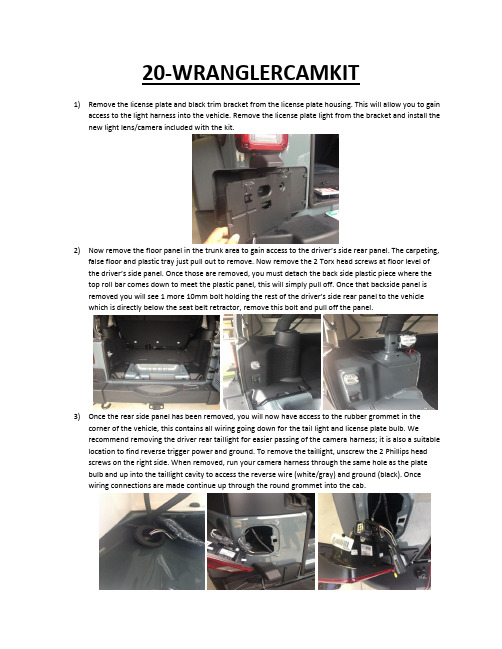
20-WRANGLERCAMKIT1)Remove the license plate and black trim bracket from the license plate housing. This will allow you to gainaccess to the light harness into the vehicle. Remove the license plate light from the bracket and install the new light lens/camera included with the kit.2)Now remove the floor panel in the trunk area to gain access to the driver’s side rear panel. The carpeting,false floor and plastic tray just pull out to remove. Now remove the 2 Torx head screws at floor level of the d river’s side panel. Once those are removed, you must detach the back side plastic piece where the top roll bar comes down to meet the plastic panel, this will simply pull off. Once that backside panel is removed you will see 1 more 10mm bolt holding the re st of the driver’s side rear panel to the vehicle which is directly below the seat belt retractor, remove this bolt and pull off the panel.3)Once the rear side panel has been removed, you will now have access to the rubber grommet in thecorner of the vehicle, this contains all wiring going down for the tail light and license plate bulb. We recommend removing the driver rear taillight for easier passing of the camera harness; it is also a suitable location to find reverse trigger power and ground. To remove the taillight, unscrew the 2 Phillips head screws on the right side. When removed, run your camera harness through the same hole as the plate bulb and up into the taillight cavity to access the reverse wire (white/gray) and ground (black). Once wiring connections are made continue up through the round grommet into the cab.4)Once through the grommet, run the harness to the front of the vehicle tucking it beneath the trim carpetand plastic panels towards the front. When at the front, remove the panel below the steering column by unclipping it. Once panel is removed, take out the 2 – 7mm bolts at each top corner of the opening. Now remove the rubber tray on top of the dash to remove 1 more bolt. Next move to the window controls which can be popped out to reveal the last bolt holding on the dash piece. Once all 4 bolts are removed, unclip the dash panel and set aside.5)With the dash panel removed, proceed to take out the factory radio by removing the 4 bolts securing it tothe dash. With the radio removed, simply plug in the harnessing that was included with the bypassmodule by t-harnessing it into the existing wiring. It is possible that the WHITE T-Harness connector may not be populated from the factory; this is not an issue so continue the install by plugging the male end into the radio. Please note: The back-up camera’s RCA will plug into the WHITE T-Harness RCA labeled “CAM IN” you will not use any RCA connections on the Gray T-Harness. Once the Gray and White T-Harnesses have been plugged in, plug the black Molex connector into the programming box. Witheverything plugged in turn on the vehicles ignition and let the radio completely boot up, if everything is connected properly simply put the vehicle in reverse and the camera image will appear.FINISHED。
MOTOTRBO车载台安装手册

第1章
简介 ....................................................................................... 1-1
1.1 车载台对讲机说明 .......................................................................................................................... 1-1 1.1.1 概述................................................................................................................................... 1-1 1.1.2 尺寸................................................................................................................................... 1-1 1.1.3 对讲机背后的接线 ............................................................................................................. 1-2
新JEEP指南者中控操作手册

客户可编程功能——Uconnect8.4设置
按下触摸屏上的Apps(应用)按钮,然后按下Settings(设置)按钮,即可显示菜单设置屏幕。
在此模式下,通过Uconnect系统可以使用所有可用的
可编程功能。
显示——按下触摸屏上的“Display(显示)”按钮后,即可使用下列设置:
1
单位——按下触摸屏上的“Units(单位)”按钮后,即可使用下列设置:
语音——按下触摸屏上的“Voice(语音)”按钮后,即可使用下列设置:
时钟:按下触摸屏上的“Clock(时钟)”按钮后,即可使用一列设置:
2
安全和驾驶辅助:按下触摸屏上的“Satety/Driving Assistance(安全/驾驶辅助)”按钮后,即可使用下列设置:
3
制动:按下触摸屏上的“Brake(制动)”按钮后,即可使用下列设置:
车灯:按下触摸屏上的“Lights(灯光)”按钮后,即可使用下列设置:
自动舒适系统—如果配备,按下触摸屏上的“Auto-On Comfort Systems(自动开启舒适功能系统)”按钮后,即可使用下列设置:
4
车门和车锁:按下触摸屏上的的“Doors & Locks(车门和车锁)”按钮后,即可使用下列设置:
5。
Baer Pro+ 后盾式车型安装说明书

Installation InstructionsProduct: Pro+ Rear Instruction Part Number: 6000545 Vehicle Revision Date: 26 January 2017 Make: Jeep Model: JK 4WD Year(s): 07-13Notices – Read and Follow BEFORE ATTEMPTING INSTALLATION∙All installations require proper safety procedures and protective eyewear.∙ All installations assume basic mechanical skill and a factory service manual for the vehicle on which the installation is to be performed.∙ All references to the “left” side of the vehicle correlate to the driver’s side of the vehicle.∙Any installation requiring you to remove a wheel or gain access under the vehicle requires use of jack stands appropriate to the weight of the vehicle. In all cases, jack stands rated for a minimum of 2-tons is recommended.∙A selection of hand tools sufficient to engage in the installation of these products is assumed, and is the responsibility of the installer to have in his/her possession prior to beginning this installation. All installations, which require removal of hydraulic hoses and/or bleeding of the brakes, require appropriate fitting/line wrenches, safety catch can, and protective eyewear. Other than these items, if unique or special tools are required they will be stated appropriately in the installation step.∙ALWAYS CONFIRM WHEEL FIT PRIOR TO BEGINNING INSTALLATION OF ANY BRAKE SYSTEM OR “UPSIZED” ROTOR UPGRADE! In addition to checking wheel fitment (available online at ), always place the actual corner assembly or a combination of the caliper assembly onto the rotor, and into the actual wheel. This procedure will reconfirm proper clearance between the caliper and the wheel before proceeding with the actual installation.∙Returns will not be accepted for systems that have been partially or completely installed. Use extreme care when checking wheel fitment to prevent any cosmetic damage.∙When installing new Baer rotors, be sure to follow the direction of rotation indicated on the rotor hat area with either an arrow, or an “L” for left, or an “R” for right, or both. “L” or left always indicates the driver’s side of US spec vehicles. Images shown are “L” left rotors:∙ A proper professional wheel alignment is required for any system requiring replacement of the front spindles, or tie rod ends. Follow factory prescribed procedures and specifications unless otherwise indicated.∙At any point, stop the installation if anything is unclear, or the parts require force to install. Consult directly with Baer Technical Staff in such instances to confirm details. Please have these instructions, as well as the part number of the component (part numbers are machined into the brackets) that is proving difficult to install, as well as the make, model, and year (date of vehicle production is preferred) of your vehicle available when you call. Baer’s Technical Staff is available from 8:30a.m. - 5:00p.m. Mountain Standard Time (Arizona does not observe Daylight Savings Time) by phone: (602)-233-1411 Monday through Friday.INSTALLATION:1. Remove all the rear end axle/brake components, caliper, rotor, axle, bracket, brake shoe, etc.Thoroughly clean the face of the axle housing flange to ensure proper fitment of the new components. Save the OEM hardware and axle retainer plate as they will be reused. The OEM brake shoe bracket will not be reused, the Baer banksia plate assembly replaces that bracket.2. Install the Baer banksia plate assembly (Figure 1). The assembly comes with the Baerintermediate bracket attached to the inboard side of the plate. The bracket bolts are just snugged as they will need to be removed for shimming later in the install.Figure 1: Baer banksia assembly (drivers side)3. Install the axle and axle retainer plate using the OEM hardware. The banksia plate will be held inplace by the OEM axle retainer plate bolts. See Figures 2 and 3 for reference.Figure 2: Banksia, axle and axle retainer plateIntermediate BracketAxle Retainer PlateBanksiaFigure 3: Banksia, axle and axle retainer plate (inboard view)4. Install the correct side rotor onto the axle and secure with two or three lug nuts and washers toprevent scratching the rotor hat. With the pads removed install the caliper (bleed screw pointing upward) using the supplied M12-1.75 x 45mm socket head bolts. Snug the bolts for now asshimming will require removal. See Figures 4 and 5 for reference.Figure 4: Rotor and caliper installed (outboard view)Figure 5: Rotor and caliper installed (inboard view)5. Perform the Shimming Procedure which is located on the last page. When the procedure hasbeen completed continue with the Step 6.6. Install the brake hose to the caliper using the supplied banjo bolt and copper washer (one copperwasher on each side of the banjo fitting). Finger tighten the banjo bolt. Connect the hose to the hardline using one of the supplied fittings and install the hose lock.***IMPORTANT: Position the hose to avoid interference with the wheel and suspension components through the entire range of motion. Tighten fitting and banjo bolt to 15-20 ft∙lbs.7. Repeat the procedure for the other side.Refer to Bleeding and Pad Bedding & Rotor Seasoning Procedures contained on a separate sheet,or on For service components and replacement parts contact your Baer Brake Systems Tech Representative.Figure 6: Shim location。
铃木吉姆尼安装博文BOWON定制DVD导航与倒车可视系统

铃木吉姆尼安装博文BOWON定制DVD导航与倒车可视系统铃木吉姆尼是由日本铃木公司生产的轻型越野车,英文名称为“JIMNY”。
她在越野爱好者族群中也享有很高的地位。
但是在中国大地上奔驰的吉姆尼,全部为进口车型。
这可爱的小车因为市场定位的原因,至今也没有国产。
下图为铃木吉姆尼安装博文BOWON定制DVD导航与倒车可视系统。
博文BOWON定制铃木吉姆尼DVD导航一体机
拆下原车主机,安装博文BOWON定制铃木吉姆尼DVD导航一体机。
博文BOWON定制铃木吉姆尼DVD导航一体机安装完毕,主菜单显示效果。
博文BOWON定制铃木吉姆尼DVD导航一体机安装完毕,使用凯立德导航地图。
博文BOWON通用BWTY-1106倒车摄像头
博文BOWON通用BWTY-1106倒车摄像头安装在牌照灯饰条上。
博文BOWON通用BWTY-1106倒车摄像头安装好的效果。
铃木吉姆尼安装博文BOWON倒车可视系统完毕,倒车影像显示效果。
BOSBO-X7全景影像行车辅助系统

荧光夜视 产品功能
采用索尼225图像传感器,夜视效果好 无惧黑暗环境泊车,晚上效果也清晰 博视宝X7
四路记录 产品功能
前后左右四路画面同时记录 全方位监控车身环境,实时记录,方便取证 博视宝X7
循环录像 产品功能
防止U盘文件满盘,导致不继续录制情况 U盘录满后,系统会自动覆盖掉最早的视频,接着录制之后的视频 博视宝X7
06:荧光夜视 07:四路记录 08:循环录像 09:停车监控 10:窄道模式 11:前后左右盲区可视
精准轨迹 产品功能
内置精准轨迹,准确预判车身行进方向。 与其他的360全景相比,不用选装轨迹盒,而且拼接后轨迹更精准,倒车更准确 博视宝X7
左右校正 产品功能
左右广角画面进行校正,视角更直观,车身更直 与其他的360全景相比,广角画面畸变小,画面显示更真实 博视宝X7
博视宝
X7·协议一体机
无损安装/精准轨迹/荧光夜视/雷达触发/左右校正
01
市场分析
针对不同车型,直接走CAN线协议 免接线,无需破线对接,安装师傅更轻松 适配性更好,专车专用 相对于使用解码器,价格上更实惠
02
产品功能
01:精准轨迹 02:左右校正 03:雷达触发 04:无损安装 05:加大内存
雷达触发 产品功能
离障碍物距离过近,雷达自动触发全景,盲区视野一目了然 此功能需原车带前后雷达信息 博视宝X7
无损安装 产品功能
免接线,免破线,专用线束直接对插原车插口 安装简单,不用另加协议盒,无损安装 博视宝X7
加大内存 产品功能
大内存,不卡顿,系统运行更流畅。 运行内存存储内存双升级 博视宝X7
谢谢欣赏
后视盲区可视
后盲区可视,倒车全景视图加后视图 准确安全安全倒车 博视宝X7
- 1、下载文档前请自行甄别文档内容的完整性,平台不提供额外的编辑、内容补充、找答案等附加服务。
- 2、"仅部分预览"的文档,不可在线预览部分如存在完整性等问题,可反馈申请退款(可完整预览的文档不适用该条件!)。
- 3、如文档侵犯您的权益,请联系客服反馈,我们会尽快为您处理(人工客服工作时间:9:00-18:30)。
吉普JEEP大切诺基安装博文BOWON泊车前后可视“大切诺基”的动力系统沿用了“切诺基”的4.0升190马力直六发动机,不久又增加了5.2升V8发动机,功率为220马力。
这是在SUV中第一个配备V8引擎的车型,它的拖拽重量可以达到6500磅(2951kg),非常适合拖带野营车,使大切诺基在同类车型竞争中有明显优势。
下图为吉普JEEP大切诺基安装博文BOWON泊车前后可视。
博文BOWON4.3寸通用型双屏倒车后视镜显示器
博文BOWON4.3寸通用型双屏倒车后视镜显示器卡在原车内视镜上。
博文BOWON4.3寸通用型双屏倒车后视镜显示器安装好的效果。
博文BOWON通用前视摄像头1658QS
吉普JEEP大切诺基安装博文BOWON通用前视摄像头1658QS的安装位置,隐蔽美观。
吉普JEEP大切诺基安装博文BOWON通用前视摄像头1658QS安装好的效果。
吉普JEEP大切诺基安装博文BOWON泊车前视完毕,泊车前视显示效果。
博文BOWON BWTY-1703通用倒车摄像头。
拆下JEEP大切诺基原车牌照灯饰条,用专用开孔器打孔安装博文BOWON 1703通用倒车摄像头。
博文BOWON BWTY-1703通用倒车摄像头安装好的效果,隐蔽美观居中。
吉普JEEP大切诺基安装博文BOWON泊车后视完毕,倒车影像显示效果。
通过开关来控制泊车前视影像。
吉普JEEP大切诺基安装博文BOWON泊车前后可视完毕,泊车前后影像同时显示效果。