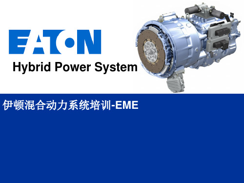
伊顿混合动力介绍General Hybrid Overview For ZT -CN
艾桑(EATON)产品说明手册说明书
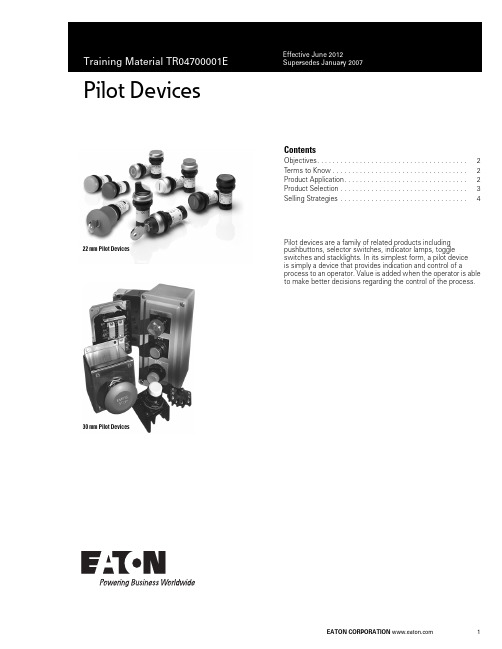
Pilot Devices1ContentsObjectives. . . . . . . . . . . . . . . . . . . . . . . . . . . . . . . . . . . . . . . 2Terms to Know . . . . . . . . . . . . . . . . . . . . . . . . . . . . . . . . . . . 2Product Application. . . . . . . . . . . . . . . . . . . . . . . . . . . . . . . . 2Product Selection . . . . . . . . . . . . . . . . . . . . . . . . . . . . . . . . . 3Selling Strategies . . . . . . . . . . . . . . . . . . . . . . . . . . . . . . . . .4Pilot devices are a family of related products including pushbuttons, selector switches, indicator lamps, toggle switches and stacklights. In its simplest form, a pilot device is simply a device that provides indication and control of aprocess to an operator. Value is added when the operator is able to make better decisions regarding the control of the process.22 mm Pilot Devices30 mm Pilot DevicesTraining Material TR04700001E Effective June 20122Pilot DevicesObjectives●Recognize opportunities●Develop solution with related components●Compete in the marketTerms to KnowThe following terms are used to describe application requirements common to industrial control systems. You should familiarize yourself with the meaning of these terms and the applications they describe.Pilot Device GlossaryProduct ApplicationPilot devices are available in many shapes and sizes based on their functionality and application. In general, devices are designed for application into two general markets: the IEC (global) market, and the NEMA (North American) market.The NEMA standard does not dictate function and appearance of pilot devices, but the standard does allow the use of industrial market segments to define such requirements.Note: The automotive market segment has adopted a RED “run” indicator standard in which red indicator lights illuminate when machinery is operating and represents a potentially unsafe condition.The IEC standard has adopted strict requirements concerning application of pilot devices. For example IEC 60204-1 requires pushbutton actuators be color-coded for universal application according to the format in the following table.IEC Color Coding Product developed for the IEC market is application-rated, requiring lighter duty-ratings than what the NEMA market requires. For this reason, product is typically 1/3 to 1/2 as expensive and is often positioned as a disposable commodity in the market. OEM customers appreciate the lower price, which reduces their burden cost that they typically pass on to the end-users.IEC standards 417-IEC-5007 and 417-IEC-5008 require START/STOP and ON/OFF controls be marked with universal symbols. Can you determine which symbol represents ON/START and which represents OFF/STOP?Term Definitioncontact The conducting part of a switch that operates with another conducting part to make or break a circuit contact block The part of a pushbutton that is activated when the operator is presseddebouncing The act of removing intermediate noise spikes from a mechanical switchdouble-break Contacts that break the electrical circuit in two placesdrum switch A manual switch consisting of moving contacts mounted on an insulated rotating shaftlatch An instruction or component that retains its state after a temporary condition occursOFF-delay A timing function that gains value when an input condition transitions from ON to OFFON-delay A timing function that gains value when an input condition transitions from OFF to ONone-shot (interval timer)A timing function that gains value when an input condition transitions from ON to OFF. Output state is maintained while timer is active.pole Number of isolated circuits in a switch devicerelay Device that controls one electrical circuit by manipulating contacts in another circuit throw Number of closed contact positions per poletransducer Device that converts physical parameters to electrical signalsColor Meaning Explanation ExamplesRed Emergency Actuate in the event of ahazardous condition oremergencyE-Stop, STOP/OFFYellow Abnormal Actuate in the event of anabnormal condition Intervention to suppress abnormal condition. Intervention to restart an interrupted automatic cycle.Green Normal Actuate to initiate normalconditionSTART/ONBlue Mandatory Actuate for a condition requiringmandatory actionReset FunctionWhite No specificmeaning assigned For general initiation of functionsexcept for emergency stopSTART/ON, STOP/OFFBlack No specificmeaning assigned For general initiation of functionsexcept for emergency stopSTART/ON, STOP/OFFPurpose:Purpose:Training Material TR04700001EEffective June 2012Pilot Devices 3Product SelectionVolume 7—Logic Control Operator Interface and Connectivity Solutions , CA08100008E, Tab 1 provides product selection tables for pushbuttons, selector switches, indicator lights, potentiometers, enclosures and related accessories. Stacklights and relatedaccessories are supported in Tab 2. The following sections provide an overview of the product groups.M22/C22 SeriesEaton M22/C22 industrial heavy-duty pushbutton lines offer a wide array of functional, attractive and ergonomically designed illuminated and non-illuminated pushbuttons, selector switches, push-pulls, alternate action and twist-to-release operators. M22 operators are available with either a silver or a black colored bezel.●22.5 mm mounting hole●M22 modular design allows customers to mix/match contact blocks and operators●C22 compact, all-in-one design gives customers a simple installation●NEMA 3R, 4X, 13 and IP67/69k on most operators ●100% LED technology throughout lines ●Fully custom laser etching available●Toolless secure assembly of mounting adapter and contact blocks ●Notched hole mounting with anti-rotation nib standard10250T SeriesThis family of pushbutton, selector switch, indicator light and potentiometer devices represents the flagship product for NEMA applications. It is easily recognized by its brilliant chrome finish.Features include:●30.5 mm mounting hole●Contact blocks feature “reliability nibs” that ensure long life and dependable switching despite oxidation and corrosion on the contact surfaces●Operators feature “grounding nibs” that ensure electrical grounding of the operator with the panel●UL 600 Vac rating, 10 million operations (mechanical), 1million (electrical)●NEMA 1/2/3/3R/4/4X/12/13 and IEC IP65 ratingsBenefits include:●New contact block design provides greater visibility with laser-engraved terminal markings and light gray material. Ultrasonic welding of contact blocks have been eliminated, making the components acceptable for low emissivity ratings required by IEC and other global market standardsE34 SeriesThe E34 family of pilot device products represents the ultimate in corrosion-resistant packaging of pilot devices. It uses the same design elements of the 10250T, but replaces the brilliant chrome finish with a triple-layer epoxy finish that is extremely durable.Features include:●Uses the same contact block, operator mounting, and accessories as the 10250T●Meets NSF requirements for corrosion resistance fromcontinuous salt spray for 200 hours. Tested to 600 hours before visible corrosion appearsBenefits include:●OEMs and panelshops may appreciate the distinctive appearance of their panels provided by the black epoxy coatings of the E34 devicesHT800 SeriesThis family of pushbuttons, selector switches, indicator lights and related accessories was developed in response to the need for a family of products that provide basic functionality at a low price without sacrificing the appearance of a panel that may contain competitive products.Features include:●30.5 mm mounting hole●Transparent contact blocks that mount two-across and interlock to prevent separation due to wiring harness stress●Contact blocks may be mounted in Left/Right or Top/Bottom positions to accommodate a variety of wiring layouts●Reduced product variation expedites delivery/setup/inventoryBenefits include:●Lower cost product with basic functionality for customers who don’t need advanced featuresE30 SeriesDo you have customers that have outgrown their control panels? This situation is obvious to anyone that walks through a facility and observes pilot devices mounted to the tops, sides and back ofexisting control panels. If so, the E30family of products provides an elegant solution by integrating the function of pushbutton and indicating light into a single operator.Features include:●30.5 mm mounting hole●Up to six operations in one package●Selector switch and potentiometer designs also available●Unique contact block locking mechanism provides easy removal of contacts without disturbing the panel-mounted operators ●Customized legends/lensesBenefits include:●This product is well-positioned for applications requiring minimal panel spaceC22M22Training Material TR04700001EEffective June 2012Pilot DevicesEaton is a registered trademark of Eaton Corporation.All other trademarks are property of their respective owners.Eaton Corporation Electrical Sector 1111 Superior Ave.Cleveland, OH 44114United States © 2012 Eaton Corporation All Rights Reserved Printed in USAPublication No. June 2012 / Z12416TR04700001EE10 Toggle SwitchesOEMs that supply equipment to commercial, retail and light industrial operations may find the E10 family of selector switches and plunger toggle switches to be an ideal solution for light-duty switching of resistive and inductive loads.Features include:●0.468 in mounting hole●Packaged in quantities of 10●1–4 poles, single and double throwBenefits include:●These operators make idealcompanions to much larger industrial switches when secondary control is required for remote operationE26 StacklightsConcerned with visibility of indicator lights, or perhaps you’d like to add audible alarms to a control panel? If so, the E26 series of stacklight products provides the solution in the most demanding environments.Features include:●Modular design allows customized appearance of colors and blink rates (clear, red, yellow, green, blue, amber)●Supports monotone, bitone, and intermittent audible alarming●Incandescent, LED or xenon strobe lampsBenefits include:●The lamps are designed to interact with a wide range of control signals, from 12 to 240V . Mounting isaccommodated through a variety of bases, including 3/4 in NPT , 3- or 4-hole designsSelection SummaryThe following table provides general guidelines for application of the various pushbutton, selector switch and indicator light products.Product ApplicationsSelling StrategiesEaton has a comprehensive selection of IEC and NEMA pilot devices as open components or assembled in packages for enclosed and MCC. Selection —Eaton provides complementary product lines in addition to the basic pilot devices. These products include metallic and nonmetallic enclosures, signal conditioning and isolation transformers, sensors and programmable controls.Customization —Warehouses in Spartanburg, SC, and Memphis, TN, support customized labeling of legend plates and lenses for all pilot devices. Order forms are included in the catalog.Ease of Installation —No tools are required for the IEC rated devices and modular assemblies support the installation of operators separate from the contact blocks for the NEMA rated devices. Products may be ordered fully assembled or as separate components.How do Eaton’s products compete ? Reinforce the capability of the 48 hour mod center, our warehouse stocking, ProShop training, regional service centers and faster delivery.ServiceNote1The E34 family of devices is sensitive to UV light when applied in outdoor applications. The devices will appear slightly discolored after long periods of exposure to direct sunlight. The functionality ofthe device is not affected.IndoorOutdoor Washdown Corrosive Explosive 10250T Yes Yes Yes No Yes HT800Yes No Yes No No E34Yes Yes 1Yes Yes Yes E30Yes No No No No M22Yes Yes Yes Yes No C22YesYesYesYesNoResourcesValue AddManufacturing Facilities(Chicago, Denver, Los Angeles, Hartford, Houston)Regional support for entire product line. Open to customer visits. Able to ship quickly. Warehouses Provide balance for distributor stocking ProShops Distributor support provides ownership of solutionMod CenterFlexibility of solutions。
伊顿 HD1 技术手册 (Ex d、Ex em 和 Ex ia) 说明书

Heat detector HD1Heat detector HD12 HD1 Heat Detector TM159 J October 2024 DISCLAIMER OF WARRANTIES AND LIMITATION OF LIABILITYThe information, recommendations, descriptions and safety notations in this document are based on Eaton Corporation’s (“Eaton”) experience and judgment and may not cover all contingencies. If further information is required, an Eaton sales office should be consulted. Sale of the product shown in this literature is subject to the terms and conditions outlined in appropriate Eaton selling policies or other contractual agreement between Eaton and the purchaser.THERE ARE NO UNDERSTANDINGS, AGREEMENTS, WARRANTIES, EXPRESSED OR IMPLIED, INCLUDING WARRANTIES OF FITNESS FOR A PARTICULAR PURPOSE OR MERCHANTABILITY, OTHER THAN THOSE SPECIFICALLY SET OUT IN ANY EXISTING CONTRACT BETWEEN THE PARTIES. ANY SUCH CONTRACT STATES THE ENTIREOBLIGATION OF EATON. THE CONTENTS OF THIS DOCUMENT SHALL NOT BECOME PART OF OR MODIFY ANY CONTRACT BETWEEN THE PARTIES.In no event will Eaton be responsible to the purchaser or user in contract, in tort (includingnegligence), strict liability or other-wise for any special, indirect, incidental or consequential damage or loss whatsoever, including but not limited to damage or loss of use of equipment, plant or power system, cost of capital, loss of power, additional expenses in the use of existing power facilities, or claims against the purchaser or user by its customers resulting from the use of the information, recommendations and descriptions contained herein. The information contained in this manual is subject to change without notice.Heat detector HD13 HD1 Heat Detector TM159 J October 2024 ContentsIntroduction............................................. 4 General safety messages and warnings........ 4 Installation.............................................. 4 General.................................................... 4 Removing/Replacing the cover............... 4 Operation......................................................... 5 Maintenance.................................................... 5 Certification / approvals................................... 6 Exd IIB Version.......................................... 6 Exd IIC Version.. (6)Ex em Version (6)Ex ia Version............................................. Special conditions of use………………………6 7Heat detector HD14 HD1 Heat Detector TM159 J October 2024 1.0 INTRODUCTIONThe HD1 heat detector has been designed for use in flammable atmospheres and harsh environmental conditions. The marine grade alloy (Exd) or Glass Reinforced Polyester (Exem and Exia versions) cover and enclosure are suitable for use offshore or onshore, where light weight combined with corrosion resistance and strength is required.2.0 GENERAL SAFETY MESSAGES AND WARNINGSAll instructions and safety messages in this manual must be followed to allow safe installation of the device. The device must only be installed and maintained by correctly trained site personnel/installers.i. To reduce the risk of ignition of hazardousatmospheres and shock, do not apply power to the device until installation has been completed and the device is fully sealed and secured. ii. To reduce the risk of ignition of hazardousatmospheres and shock, keep device tightly closed when the circuit is energised.iii. Before removing the cover for installation ormaintenance, ensure that the power to the device is isolated.iv. Following installation, test the device to ensurecorrect operation.v. Following installation ensure a copy of this manualis made available to all operating personnel. vi. When installing the device, requirements forselection, installation and operation should be referred to e.g. IEE Wiring Regulations and the National Electrical Code’ in North America.Additional national and/or local requirements may also apply.vii. Cable termination should be in accordance withspecification applying to the required application. MEDC recommends that all cables and cores should be correctly identified. Please refer to the wiring diagram in this manual (or separate diagram provided with the unit).viii. Ensure that only the correct listed or certified cableglands are used and that the assembly is shrouded and correctly earthed.ix. Ensure that only the correct listed or certifiedstopping plugs are used to blank off unused gland entry points and that the NEMA/IP rating of the unit is maintained.x. MEDC recommend the use of a sealing compoundsuch as HYLOMAR PL32 on the threads of all glands and stopping plugs in order to maintain the IP rating of the unit.xi. For the Exem and Exia versions, a suitable sealingwasher must be fitted to all glands and stopping plugs fitted into the enclosure.xii. The internal earth terminal, where fitted,must be used for the equipmentgrounding and the external terminal, if available, is for a supplementary bonding connection where local codes or authorities permit or require such a connection.xiii. When installing the device, MEDCrecommends the use of stainless steel fasteners. Ensure that all nuts, bolts and fixings are secure.xiv. Note: The purchaser should make themanufacturer aware of any externaleffects or aggressive substances that the equipment may be exposed to.xv. Potential electrostatic charging hazard,protect from direct airflow from exhaust ducts and the like which may cause charge transfer. If the unit requires cleaning, only clean the exterior with a damp cloth to avoid electrostatic charge build up. Ensure the equipment is correctly earthed.xvi. Installation shall be in accordance withIEC60079-14.3.0 INSTALLATIONGeneralThe heat detector is mounted via 4 off Ø9mm (Exd version) or 4 off Ø7mm (Exem and Exia versions) fixing holes in feet on the base of the unit.The fixing holes have been designed to accept M8(Exd version) or M6 (Exe/Exi versions) screws or bolts.The heat detector has been designed to operate in any attitude.Removing/replacing the Cove rExd version: Unscrew and remove the 4 off M6 screws (5mm A/F hexagon key required) and lift the cover clear of the base. The screws are not captive and should be kept in a safe place during cable termination.Exem/Exi versions: Unscrew the 4 off M5 screws (4mm A/F hexagon key required) and lift the cover clear of the base. The cover screws are captive and will be retained in the cover.Once cable termination has been completed, the cover can be replaced and secured to the enclosure. Ensure that any cover seal is correctly seated.On Exd versions ensure that the gap between the cover and enclosure is 0.15mm max. .Heat detector HD15 HD1 Heat Detector TM159 J October 2024 4.0 OPERATIONThe heat detector consists of a sealed element containing a single normally open (N.O.) thermal switch which operates at a fixed temperature. The operatingtemperature is stated on the identification label on the outside of the unit.The sensor element is fully sealed, and no attempt must be made to modify this in any way. Adjustment of the temperature setting is not possible.General arrangement (exd version)General arrangement (exe/exi versions)5.0 MAINTENANCEDuring the working life of the heat detector it should require little or no maintenance. However, if abnormal or unusual environmental conditions occur due toplant damage or accident etc., then visual inspection is recommended.If a fault should occur, then the unit can be repaired by MEDC.Under no circumstances should any attempt be made to either unscrew the heat detector element from the enclosure or gain access to the inside of the heat detector element.Either of these actions will result in the assembly becoming unsafe for use in potentially explosive atmospheres.If you have acquired a significant quantity of heat detectors, then it is recommended that spares are also made available. Please discuss your requirements with MEDC’s technical sales engineers.If the unit requires cleaning, only clean exterior with a damp cloth to avoid electro-static charge build up.Heat detector HD16 HD1 Heat Detector TM159 J October 2024 6.0 CERTIFICATION / APPROVALSExd IIB version: Certified toATEX: EN60079-0 , EN60079-1 , EN60079-31, IEC60079-33IECEx: IEC60079-0 , IEC60079-1 , IEC60079-31, IEC60079-33Ex d unit(ATEX certification No. Baseefa 03ATEX0447) (IEC certification No. IECEx SGS 24.0013X.)Ex db sb IIB+H2 T6 (Tamb -20°C to +55°C) Ex tb IIIC T85°C Db IP6x OrEx db sb IIB+H2 T3 (Tamb -20°C to +125°C)* Ex tb IIIC T200°C Db IP6x*Please refer to certification label for temperature ratingExd IIC version: Certified toATEX: EN 60079-0, EN 60079-1, EN60079-31, IEC60079-33IECEx: IEC60079-0 , IEC60079-1 , IEC60079-31, IEC60079-33Ex d unit(ATEX certification No.Baseefa08ATEX0320) (IEC certification No. IECEx SGS 24.0012X.)Ex db sb IIC T6 Gb (Tamb -20°C to +55°C) Ex tb IIIC T85°C Db IP6X OrEx db sb IIC T4 Gb (Tamb -20°C to +90°C) Ex tb IIIC T135°C Db IP6XFor Type HD1 Addressable Heat Detector Units which do contain an addressable module the marking remains as:Ex db sb IIC T6 Gb (Tamb -20°C to +55°C) Ex tb IIIC T85°C Db IP6XThe Exd ATEX certificate and product label carry the ATEX group and category marking:II 2 GD Where:Signifies compliance with ATEXII Signifies suitability for use in surface industries 2 Signifies suitability for use in a zone 1 areaG Signifies suitability for use in the presence of gases D Signifies suitability for use in the presence of dustThe IECEx certificate and product label carry the IECEx equipment protection level markingGb and Db where Gb signifies suitability for use in a Zone 1 surface industries area in the presence of gas.Db suitability for use in a Zone 21 surface industries area in the presence of dust.Exe version: Certified toATEX: EN60079-0 , EN60079-7, IEC60079-33 IECEx: IEC60079-0, IEC60079-7, IEC60079-33(ATEX certification No. Baseefa03ATEX0428) (IEC certification No. IECEx SGS 24.0035X) Ex eb sb IIC T6 Gb (-20°C to +55°C) (With resistors fitted)Ex eb mb sb IIC T4 Gb (-20°C to +55°C)The ATEX certificate and product label carry the ATEX group and category marking:II 2 G Where:Signifies compliance with ATEXII Signifies suitability for use in surface industries 2 Signifies suitability for use in a zone 1 areaG Signifies suitability for use in the presence of gasesThe IECEx certificate and product label carry the IECEx equipment protection level marking GbWhere Gb signifies suitability for use in a Zone 1 surface industries area in the presence of gas.Ex ia version:ATEX: Certified to EN60079-0 & EN60079-11 IECEx: Certified to IEC60079-0 & IEC60079-11(ATEX certification No. Baseefa03ATEX0427) (IEC certification No. IECEx BAS 13.0010)Ex ia IIC T6 Ga (-55°C to +55°C) - HD1I version Ex ia IIC T4 Ga (-55°C to +55°C) - HD1IR versionThe Ex ia ATEX certificate and product label carry the ATEX group and category marking:II 1 G Where:Signifies compliance with ATEXII Signifies suitability for use in surface industries 1 Signifies suitability for use in a zone 0 areaG Signifies suitability for use in the presence of gasesThe IECEx certificate and product label carry the IECEx equipment protection level marking Ga.Where Ga signifies suitability for use in a Zone 0 surface industries area in the presence of gas.Heat detector HD17 HD1 Heat Detector TM159 J October 2024 7.0 SPECIAL CONDITIONS OF USEExd IIB/IIC version:1. Cover screws of minimum grade A4-80stainless steel shall be used. 2. Warning – Potential electrostaticcharging hazard – See instructions.Exe version:For HD1R units only:1. The electrical supply to the encapsulatedResistor is limited to a maximum of 1.2W 2. Units fitted with the encapsulated resistorshall be protected by a fuse rated for a prospective short circuit current of at least 1500A .Heat detector HD18HD1 Heat Detector TM159 J October 2024 EatonEMEA Headquarters Route de la Longeraie 7 1110 Morges, Switzerland Eaton.euEatonUnit B, Sutton Parkway Oddicroft Lane Sutton in Ashfield United Kingdom NG17 5FBT: +44 (0) 1623 444 400 /hac*******************© 2024 EatonAll Rights Reserved Printed in September Publication No. TM159/J Changes to the products, to the information contained in this document, and to prices are reserved; so are errors and omissions. Only order confirmations and technical documentation by Eaton is binding. Photos and pictures also do not warrant a specific layout or functionality. Their use in whatever form is subject to prior approval by Eaton. The same applies to Trademarks (especially Eaton, Moeller, and Cutler-Hammer). The Terms and Conditions of Eaton apply, as referenced on Eaton Internet pages and Eaton order confirmations.Eaton is a registered trademark.All trademarks are property of their respective owners.。
伊顿混合动力系统--发动机要求

speed, point 7
TX
Maximum momentary engine override
time limit
TX
Requested speed control range lower limit
TX
Requested speed control range upper limit
TX
Cruise Control/Vehicle Speed (CCVS)
Engine Torque Mode Driver's Demand Engine - Percent Torque (DDPT) Actual engine percent torque (AEPT) Engine Speed Source Address of controlling device for engine control
TX
Percent torque at idle, point 1
TX
Engine speed at point 2
TX
Percent torque at point 2
TX
Engine speed at point 3
TX
Percent torque at point 3
TX
Engine speed at point 4
0
0.1
Wheel Based Vehicle Speed
Crusise Control Active
Cruise Control Enable
Brake Switch Crusise Control Set Switch
Cruise Control Set speed
Maximum vehicle speed limit
Eaton 电源分发板产品介绍说明书

Distribution switchboardsThe broadest offering in the industryIndustry-leading Eaton switchboardsEaton’s electrical group offers the widest selection of switch-board types in the industry, and this is only the start.Our switchboards are built from the ground up based on customer input and needs. From the simplest 800A switchboard to Web-enabled, Eaton switchboards offer flexibility in designs to accommodate any power distribution need you have.Our flexible designs are onlyas good as the people andservice that bring the productsto you. Eaton has uniquelypositioned manufacturingcenters of excellencethroughout the United States.Our 18 facilities, strategicallylocated near our customers,provide more than just switch-boards and panelboards. Theyare your personal plants. TheseRegional Manufacturing Facilitieshave the capability of muchlarger facilities. They understandyour needs and your markets...because they are right there.Our goal, and the goal of ouroutstanding sales team, is toexceed your expectations.From emergency shipments tolarge projects, from new con-struction to aftermarket and ren-ovation, we have the experienceand expertise to help you.As you review the productsin this brochure, rememberthat this is only a samplingof our capabilities. To learn more,we invite you to contact yourlocal sales office or plant, andto come visit us.178429365Pow-R-Line C switchboardsEaton’s distributionswitchboards combine a space-saving design with modular construction and increased systems ratings to provide economical anddependable electrical system distribution and protection.Features•6000A maximum main bus rating • 600 Vac and below • Front or rear accessible • Indoor or outdoor enclosures •ANSI-61 gray powder coat paint finish•Microprocessor-based metering, monitoring and communication devices • Utility metering provisions •Surge protective devices (SPD)• Ground fault protection •Busway and transformer connections• Integrated panelboards (IFS E )•65 kAIC standard bus bracing; optional 100 or 200 kAIC •Aluminum or optional copper bus•Meets NEMA Standard PB-2 and UL 891•Seismically qualifiedMain devices•Magnum E DS power circuit breakers, 800–5000A • Molded-case circuit breakers, 400–2500A, fixed mounted •Pringle bolted pressure contact switches, 800–5000A •Fusible switches, 400–1200A1. Utility MeteringCompartmentsAvailable to meet standard or specific requirements. Units can be arranged for hot or cold sequence.2. Single Chassis DesignProvides device flexibility, accommodating both circuit breaker and fusible switches.3. Pow-R-Line C SwitchboardsGroup-mounted distribution switchboards.6. Electronic T rip Unit SystemAdvanced technology options offer superior protection, energy management and communications.7. Surge Protective DeviceIntegrally mounted with overcurrent feeder.Electronic trip unit systemEaton electronic trip units provide enhanced accuracy and reliability for protection and optimum system coordination.Surge protective devicesEaton’s surge protectivedevices (SPDs) protect sensitive electronic equipment from the damaging effects of high and low energy transients, as well as high-frequency noise.The SPD, combined with our innovative connection, yields the industry’s lowest let-through voltage.Wide range of surge ratings Surge current ratings from 100 to 400 kA per phaseprovide a range of cost-effective facility-wide protection solutions. Products are third-party tested to verify published surge current ratings.SPD mounted within the enclosure eliminates extra wiring and the need for outboard wall space:•UL 1449 Listed high-performance suppression system and parallel hybrid filter technology • Diagnostic system •Integral circuit breaker disconnect4. Eaton Molded-CaseCircuit Breakers 225A, electronic tripframe (left); 600A, electronic trip frame (middle); and 2500A, electronic trip frame (right).5. Magnum DS PowerCircuit Breakers8. Metering and MonitoringDevicesPower Xpert Gateway (front) and IQ 250 Meter (back).9. Eaton’s Power XpertCommunications System, Programming and Monitoring Accomplished remotely from a personal computer via the Web.Group-mounted distribution devices•Molded-case circuit breakers, 15–2000A•Fusible switches, 30–1200AMetering andmonitoring devicesA wide range of metering options for power measurement and power quality is available. Along with local display, these meters can provide Web-enabledmonitoring of Eaton switchboards and other equipment via an open communications architecture. The Power Xpert Gateway enables third-party equipment to communicate across this same system.DistributionswitchboardsIQ Energy SentinelsPower and energy information from IQ Sentinels can be communicated to a PC, a panel-mounted central energy display (CED), or even existing building management or distribution control systems.IQ Energy SentinelsCost-effectivesubmetering throughout the electrical systemThese devices monitor power and energy readings down to the smaller loads. They measure watts, peak demand andwatt-hours within a one-percent accuracy level.The device mounts directly on F-, J- or K-Frame feeder breakers without requiring additional panel height. A universal sentinel is available where breaker mounting is not feasible and for the larger frame breakers.162345Pow-R-Line i switchboardsPow-R-Line i distributionswitchboards are engineered in a compartmentalized design for applications where a greater degree of component isolation is required. A wide variety of configurations is possible, including utility metering, customer metering, main devices, branch devices, accessories and enclosures.Significant safety features•Individual compartments for branch devices help eliminate possible contact with the main bus and reduce fault propagation•Three-section construction with each barriered from the other:•Device section —each device is mounted in its own compartment•Busbar section —contains both horizontal and vertical busses•Rear cable compartment — completely isolated from the busbars•Insulated runbacks, so that power is taken from the protective device by the runback through a full-height glass-polyester barrier to the rear cable compartment, virtually eliminating the possibility of accidental contact with the main busses during installation or maintenanceConstruction features•Full family of metering and protective devices available •Custom-built utility metering compartments •Individually mounted main devices•Compartmentalized feeder devices•Meets NEMA Standard PB-2 and UL 891• Rear accessible•65 kAIC standard bus bracing; optional 100 and 200 kAIC •Aluminum or optional copper busbar •ANSI-61 gray powder coat paint finish •Indoor and outdoor enclosures•Seismically qualifiedA wide selection of branch devices Circuit breakersBranch circuit breakers range from 150A to 1200A Fusible switchesBranch fusible switches are avail-able from 100A to 1200A frames1. Branch Circuit BreakersShown in single- and tandem- mounted construction.2. Fusible SwitchesBranch fusible switches in single-unit construction.5. Laser Cut andPower Coat FinishLaser cut panelboard trims with a high-quality baked-on powder coat finish provides a high-quality appearance.6. Benefits of IFSIFS can be integrated with service equipment wherepanelboards are needed in the electrical distribution equipment room. IFS lowers installation time and saves space.Integrated facility systems (IFS)Eaton is the industry leader in integrated switchboards with more than 100,000 IFS sections delivered to customers. Eaton’s Integrated Facility Systems E (IFS) switchboards can reduce the overall space requirement over traditional panelboard and transformer installations. Because IFS is factory assembled and wired between major components, there are fewer pieces to handle and install, thus reducing installation time.IFS is ideal for both new construction and renovation. Each IFS switchboard is custom designed to meet customer requirements. Specificrequirements for panelboard configurations, as well as transformers and otherequipment, can be customized into IFS switchboards. Eaton’s experience andcapabilities ensure that your IFS is configured to yourexacting standards and delivered on time from one of Eaton’s 18 assembly plants.Standard panelboard andtransformer configurations can ship in as few as two weeks. These include IFS sections with 480Y/277 Vac lighting panelboards with a feeder to a NEMA TP1 transformerfeeding one or more 208Y/120 Vac panelboard(s). All breakers are installed to your drawings and factory wired between the transformer feeder device and the 208 Vac lighting panelboard.3. Pow-R-Line i SwitchboardsCompartmentalized design for increased device isolation.4. Barriered ConstructionOvercurrent devices isolated from bus.Features• Single - and three-phase • 600 Vac maximum• Integrated lighting panelboards • Integrated power panels • Lighting control •Dry-type distribution transformers• Breakers and fusible devices •Provisions for customer- installed equipmentIFS Space-Saving CapabilitiesAn IFS switchboard can significantly reduce the size of an electrical room. Replacing traditional panelboards and transformers with IFS can free up valuable space for the owner. Ideal for facility electrical upgrades where space is limited.Factory Installed WiringTransformers are pre-wired in Eaton’s assembly facility from the primary side feeder (when in the same switchboard) to the secondary overcurrent device. All wiring is marked “Factory Installed” using industry convention colored wire markings. All factory cabling is in accordance with the National Electrical Code using the same standards as field wiring.• Special heights and depths • Metering•UL 891 Listed and meets NEMA PB-2 standards • Seismically qualified • Designs for raised floors •Indoor and outdoor enclosures•Automatic transfer switches1523467Commercial metering switchboardsEaton offers a number of options for commercialmetering switchboards. These include assemblies that meet utility requirements for bulb type watt-hour meters and electronic tenant metering switchboards.Features•Free-standing switchboard construction•Factory-assembled complete with interconnections from incoming mains to the meter and to the tenant main •UL 891 Listed and meets NEC and NEMA PB-1 standards • Seismically qualified •Indoor and outdoor enclosuresUtility type watt-hour meter switchboards•Available with different meter socket configurations:•EUSERC- approved designs through 200A•Lever bypass meter sockets through 400A•Choice of fusible or circuit breaker tenant mains •Hot or cold sequences metering provisionsElectronic tenant metering•Ideal for third-party metering of tenants •Capabilities to read meters remotely• Revenue-grade accuracy •Monitor tenants and loads from 30A through 400A1. WWCMS ConstructionAssembly includes meter socket and test block perEUSERC requirements, pre-wired to tenant disconnect.2. WCMS ConstructionTypical 200A seven-jaw sockets with manual lever bypass connected to circuit breaker disconnects in hot sequence arrangement.3. IQ Multipoint EnergySubmeter II T enant Mains and Sensors5. IQ Multipoint EnergySubmeter II T enant Metering Switchboard 6. Eaton’s Electronic T enantMetering with QuadlogicMeters87. Quadlogic with IntegratedCommunications, Load Profiling, Time-of-Use Data 8. Pow-R-Line C InstantSwitchboardsPreassembled and available from stock.9. Seismic QualificationPow-R-Line Cinstant switchboardsInstant switchboards include EUSERC utility metering provisions and a fused main switch with optional distribution panelboard.Construction features•Completely enclosed with front, rear and side covers •Manufactured of code-gauge steel with ANSI-61 gray powder coat paint finish •Indoor and outdoor enclosures•Outdoor units include front hinged padlockable door •UL Listed and meets EUSERC, NEC and NEMA standards •Seismically qualifiedService ratings•120/240 Vac(singe-phase, three-wire)• 208Y/120 or 240/120 Vac (three-phase, four-wire)• 480Y/277 Vac(three-phase, four-wire)Metering compartment• Meets EUSERC standards •Barriered hot sequence CT provisions•Provisions for meter socket with test block provision •Hinged sealable compartment doors•Standard section includes two 15-inch-high doors (one for socket, one blank)Main switch•400A, 600A or 800A main overcurrent devices •Load lugs or connection to panelboard•Hinged cover with interlockDistribution panelboard• Factory installed •Provisions for bolt-on circuit breakersEaton switchboards Quality construction Parts are manufactured to exacting specifications to ensure precision construction of stable, rigid structuresSeismic qualificationEaton switchboards are seismically tested and qualified to exceed requirements of theUniform Building Code (UBC), the California BuildingCode (CBC) and the International Building Code (IBC)Quality assuranceFinal testing helps ensure that each switchboard performs in accordance with UL standards and customer specificationsAll switchboards are backed by Eaton’s commitment to quality, safety and reliability.4. T ype WCMS (left) and T ypeWWCMS (right)Reliable multiple circuit distribution and metering for commercial applications.•Choice of two metering solutions:•Eaton IQ Multipoint Energy Submeter II •Quadlogic•Software and communications packages•Secured remote access14365171. Receptacles Sub-AssemblyReceptacles are color-codedfor Phase A, B and C, neutraland ground.Roll-up generatorQuick ConnectswitchboardProduct descriptionThe Eaton generator QuickConnect switchboard is anengineered assembly designedto allow safe and fast connectionof a mobile generator to yourfacility’s electrical system or aportable load bank.Through inclusion of cam-typereceptacles, standard mechanicallugs, dedicated generator-servicedisconnect and a manual key-interlock transfer scheme, youcan quickly and safely supplybackup power to parts of yourelectrical power system that arenot currently covered by yourpower system, or you can backup existing generators.Loads connected to thegenerator quick connectswitchboard can immediatelybe safely transitioned to analternative power source,made possible by the generatorquick-connect switchboard.Specifications• UL 891 Listed switchboard• 480 Vac and below• Sizes 400A–4000A• Indoor and outdoorenclosures• Key interlocked mainovercurrent devices• Quick-connects to speedand simplify generatorconnections2. Generator Quick ConnectSwitchboard2000A Quick Connectswitchboard with key interlockedmain and generator connections.3. Customized, Design-Buildand Retrofit Solutions4. Panelboards and EnclosedBreakers Up to 1200A5. Switchboards Up to 6000A6. Emergency Quick Shipand Pickup7. Satellite PlantsBenefits of the generatorQuick Connect switchboardSpeed of connectionThe owner does not haveto do any of the following thatare common roll-up generatorpower situations:• No making additional fieldmodifications to an internalswitchboard in order toconnect the generator cablesafter the initial installation• No modifying the building’sphysical structure toaccommodate generatorcables (e.g., drilling holesin walls)• No running cables throughdoorways or windows andthrough hallways or up stairsSafer and more reliableReduction of the potentialfor safety problems associatedwith connecting the mobilegenerator to the facility’selectrical system underlost-power conditions• A permanent connectionpoint for mobile power, nota temporary connection• Installed under normalcircumstances, not duringa possibly chaotic lostpower situation• Tested as part of theinstallation, providingassurance when needed• Eliminates the safetyhazards of generator cablesrun through doorways andup stairways; building doorsand/or windows remainclosed for security andsafety reasonsAs part of the larger assembly,there are several sub-assembliesthat provide greater function andbenefit to facilities• Generator ServiceDisconnect—A UL Listed circuit breakerinterlocked with the servicedisconnect. The generatordisconnect can be rated upto 4000A continuous andmay include ground faultSatellite manufacturingfacilitiesBest service in the industryEaton’s switchboards are custom-built to your requirements usingworld-class manufacturingtechniques. Eaton is the onlyelectrical manufacturer that notonly uses huge manufacturingplants to meet the needs ofour customers, but also has16 smaller Satellite BusinessCenters across the countryto cater to your individualneeds. We’re probably rightin your backyard!protection, shunt trips, alarms,single-phase protection andauxiliary contacts. Such optionscan allow for integration intoa larger control system toaccomplish load sheddingwhile the facility is underbackup power• Cam-Type ReceptacleSub-Assembly—Designed to work with thecam-type plugs commonlyfound on mobile generatorcables. Includes color-codingfor easy phase connectoridentification to help ensureproper field connection ofthe generator• Permanent OperationInstructions—Affixed to each generatorquick-connect switchboard.Through the inclusion ofthese simple instructions,operation of the mechanismscan be performed by anyauthorized personnel• Generator Connection Lugs—In addition to the cam-typereceptacles, a set of standardmechanical lugs is providedwith the generator quick-connectSwitchboard to allow analternate method of connectinggenerator cables• Bus ConnectionSub-Assembly—All connection methodsdescribed previously areconnected together using onlyfactory stamped and formedbus. Bus connection, asopposed to cable, providesa more robust and smallerconstruction Located at strategic locationsthroughout the United States,these facilities manufactureand deliver standard orcustom Eaton brandedassembled switchboards,as well as panelboards andenclosed circuit breakers, whenand where you need them. Andwhen you have an emergency,they can have your equipmentready in just hours! Highlytrained and experiencedpersonnel will manage yourorder and ensure that youreceive on-time delivery ofhigh-quality equipment thatmeets your specifications.Speedy delivery• Panelboards—from oneto five days• Switchboards—between fiveand 10 days• Assembled enclosedcircuit breakers—fromone to 10 daysFor more informationFor more information, contactyour Eaton representative orauthorized distributor.SeattleSan FranciscoLos AngelesPhoenixDenverChicagoClevelandBaltimoreSumterWindsorNewJerseySt. LouisDallasHoustonAtlantaRaleighOrlandoEaton’s Electrical Sector isa global leader in power distribution, power quality, control and automation, and monitoring products. When combined with Eaton’s full-scale engineering services, these products provide customer- driven PowerChain E solutions to serve the power system needs of the data center, industrial, institutional, public sector, utility, commercial, residential, IT, mission critical, alternative energy and OEM markets worldwide. PowerChain solutions help enterprises achieve sustainable and competitive advantages through proactive management of the power system as a strategic, integrated asset throughout its life cycle, resulting in enhanced safety, greater reliability and energy efficiency. For more information, visit /electrical.Eaton Corporation Electrical Sector1111 Superior Ave. Cleveland, OH 44114United States877-ETN-CARE (877-386-2273) © 2010 Eaton CorporationAll Rights ReservedPrinted in USAPublication No. BR01500001E / Z10437 December 2010PowerChain Management is a registered trademark of Eaton Corporation.All other trademarks are property of their respective owners.。
伊顿 DB4BM 数据表(UL)DSMU0034.B EN 数据表

OverviewThe DB4BM is a high power explosion proof, metallicloudspeaker, with outstanding intelligibility and acoustic performance.Certified for use in a wide range of temperatures from -76°F to +185°F , the Ex enclosure is manufactured in either marine grade alloy or stainless steel with a rugged thermoplastic flare providing a corrosion free and aesthetically pleasing product.The frequency response of the unit ensures that critical voice messages and general alarm tones are highly intelli-gible. The specific SPL figure for sensitivity, 1W @ 10 feet is 94dB whilst at 10 feet the 25W unit produces 109dB, the 15W unit 107dB and the 8W unit 104dB.Features•UL certified for USA and CanadaClass I, Div 1, Groups A, B, C & D (CNL B, C & D)Class I, Div 2, Groups A, B, C & D Class I, Zone 1Class II, Div 2, Groups F & G Zone 21 Class III, Div. 2Fire alarm and general use • Certified temperature -60°C to +85°C (-76°F to + 185°F)• IP66 & IP67 and NEMA 4x & 6• SIL 2 certified• Up to 109dB output @ 10 feet • 8W, 15W & 25W versions•Power tappings, via integral transformer• Frequency response 350Hz - 8kHz • Ex enclosure - Stainless steel or marine grade alloy• Flare - High impact thermoplastic polyester• Stainless steel mounting bracket and cover screws• Mounting bracket has ratchet facility as standard• Optional swivel bracket available •Optional resettable fuse†† Contact MEDC for detailsOptions include DC blocking capacitors for monitored systems, resettable fuses for compliance with marine regulations and a swivel bracket that gives the installer greater flexibility when positioning the unit. The short flare option is a worthy addition to the range offering a high SPL and wide dispersion angle in a compact unit.DB4BM loudspeaker range up to 25 wattsHazardous & ordinary locations All specifications, dimensions, weights and tolerances are nominal (typical) and Eaton reserve the right to vary all data without prior notice.No liability is accepted for any consequence of use.EatonUnit B, Sutton Parkway Oddicroft Lane Sutton in Ashfield United Kingdom NG17 5FBT : +44 (0) 1623 444 /hac *******************© 2024 EatonAll Rights Reserved Printed in UK PublicationNo.DSMU0034/B March 2024Eaton is a registered trademark.All other trademarks are property of their respective owners.UL certifiedClass I, Div. 1 Groups A, B, C & D (CNL Groups B, C & D)Class 1 Div. 2 Groups A, B, C & DZone 1 Ex db IIC Gb / AEx db IIC Gb T3/T4/T5/T6Class II, Div. 2 Groups F&GZone 21 Ex tb IIIC Db / AEx tb IIIC Db T200°C/ T135°C/ T100°C/ T85°C Class III, Div. 2UL Ord Locs UL certified for USA and Canada, listing no S8447Flare - flame retardant, high impact, UV stable, thermoplastic polyester (UV stability tested to ISO 4892 part 3)Hardware - bracket, fixings and captive cover screws in 316 stainless steelFire retardancy Outer flare - thermoplastic polyester. V0 flammability rating Finish Body - Painted BlackFlare - Natural black, natural red or painted as specified Rated power 8W, 15W or 25WFrequency range Frequency response 350Hz to 8kHz8W and 15W units are available for use @ 200HzWeightAlloy 9¾ lbs/ 4.4 kg, stainless steel 18½ lbs/ 8.35 kg based on long flare DC unitIngress protectionIP66 & IP67* / NEMA 4x & 6* Full IP rating applies to terminal chamber only. High pressure jets should not be aimed directly into the re-entrant horn. IP65 Short Flare version.Entries Up to 2 x M20, M25, ½” or ¾” NPTBlanking plug must be supplied with 2 x entries T erminals8 x 12AWGMounting arrangement Stainless steel bracket with ratchet facility, optional swivel bracket avail-able8Ω is requiredsteel has swivel as standard* Specify valueThe following code is designed to help in selection of the correct unit. Build up the reference number by inserting the code for each component into the appropriate boxOrdering requirementsDSMU0034/B 03/24。
伊顿电力保护解决方案及伊顿船用 UPS 解决方案说明书

伊顿电力保护解决方案关于伊顿伊顿是一家多元化的动力管理公司,致力于提供高效节能的解决方案,帮助客户更有效的管理电力、液压和机械动力。
伊顿于 2012年 11月收购了库柏工业集团。
2012年伊顿和库柏两家公司的总销售额为 218亿美元。
伊顿在许多工业领域都是全球技术领导者,包括电气产品;电能质量、输配电及控制系统和服务;电力传输、照明和布线产品;工业设备和移动工程机械所需的液压动力元件、系统和服务;商用和军用航空航天所需的燃油、液压和气动系统;以及帮助卡车和汽车提升性能、燃油经济性和安全性的动力及传动系统。
伊顿拥有约 10.3万名员工,产品销往 175多个国家和地区。
自 1993 年进入中国以来,伊顿公司通过并购、合资和独资的形式在中国市场持续稳步增长,旗下所有业务集团——电气、宇航、液压和车辆都已在中国制造产品和提供服务,并把亚太区总部设在上海。
伊顿中国目前拥有 18 个主要的生产制造基地,超过 10000 名员工、 4 个研发中心,年销售额超过 10 亿美元。
我们坚信,如此全面出众的产品组合以及覆盖大众分销、专业电源行业以及 IT 渠道的优秀销售网络,将极大加强伊顿的整体竞争力,进一步巩固和推进伊顿的市场领导地位。
伊顿中国电能质量业务部介绍伊顿公司旗下伊顿电气集团百年来一直致力于电力应用安全,为客户提供包括整体方案前期规划、产品配置和售后服务在内的一站式服务,更有丰富的产品系列涵盖电源品质、输入输出配电、机柜、制冷和机房气流管理、电力监控和管理,为客户提供高效、安全、可靠的整体解决方案。
伊顿电气电能质量业务部提供业界领先的不间断电源( U PS )产品的同时,不断开发适合不同行业的整体解决方案,为客户提供更丰富的产品以及更多附加值的服务,成为深得客户信赖的电能质量管理的合作伙伴,从而实现了从产品技术供应商到电能质量管理整体解决方案供应商的转变,长期拥有中国 UPS 市场份额第一的位置。
在过去的一个世纪里,伊顿电气始终坚持创新,不断丰富产品,精进技术,追求品质,完善服务。
伊顿混合动力培训概论
伊顿混合动力系统主要部件
电子离合器执行器 (ECA) •安装在离合器壳体上,与 拨叉轴花键连接 •电机驱动取代传统离合器 操作系统 •由HCM通过CAN总线控制 •内部有无刷永磁电机,电路 板,位置传感器,行星齿轮机 构以及电磁锁止机构 •无需维护调整
8针 CAN500
14
3针 12V或24v电源
6
伊顿混合动力系统主要部件
操作面板(PBSC) •驾驶员操作界面 •可通过故障灯闪烁,警示驾驶员 系统有故障 •与TECU连接
7
伊顿混合动力系统主要部件
混合动力驱动单元(HDU)
电动选换档机构
离合器
ECA
8
变速箱本体
电机/发电机
HCM/TECU
伊顿混合动力系统主要部件
变速箱本体 •6个前进档及一个倒档 •基于伊顿成熟的AMT变速器 •用滑动齿套取代同步器
19
系统理论-发动机启动模式
1. 通过混合动力电机启动
• 旋转点火钥匙至启动 • HCM向逆变器发送信号,要求混合动力电机/发电机运转以启动发动机 • 逆变器向混和动力电机输送高压交流电 • HCM发送扭矩指令给发动机控制模块 • 当发动机点火后发送反馈信号给HCM进行确认 • HCM发送指令给ECA离合器分离
5
伊顿混合动力系统主要部件
逆变器
•安装在整车上 •与电池包及逆变器连接
•按混合动力控制单元指令, 实时监控整个高压系统
•把电池包的高压直流电转换 成高压交流电,传输给电机
•把发电机的高压交流电转换 成高压直流电,输送给电池 包充电
冷却液接口 (2个)
直流高压接口 交流高压接口
低压数据接口 (23针)
2. 通过启动马达启动
Eaton HEV技术背景文件说明书

Eaton and Hybrid Electric Vehicle Powertrains- Past, Present, and FutureEaton’s HEV Roots Go DeepEaton Corporation has been involved in the evolution of electric and hybrid vehicles for over 20 years. During the late 1970s and throughout the 1980s, Eaton was heavily engaged in electric vehicle research and development helping to pioneer important technological advances such as the migration from brush-type DC motors to brush-less induction motors. Early projects included the installation of complete electric traction drive systems into Ford and Chrysler passenger car and light truck applications. In the late 1980s, Eaton put its electric vehicle program on hold because of the gap in commercially viable battery technologies. This proved to be a wise decision, since most electric vehicle programs were dropped throughout the industry during the ‘90s and replaced with hybrid electric and fuel cell vehicle programs.During this time, as Eaton continued to monitor these developments, they became convinced that battery technology for hybrid electric applications was approaching commercial viability. At the same time, forward-thinking end users and truck OEM customers were becoming more receptive to the idea of hybrid electric vehicles (HEV).Eaton Forms HEV Business Unit- Sharpens FocusIn January 2000, Eaton launched itself into the HEV world with an internally funded R&D program aimed at building a Class 7 prototype hybrid truck. In March 2000, Eaton formed an HEV powertrain business unit within their Truck Electronic Systems Division, focusing human talent and resources toward the development of commercially viable hybrid powertrain systems. The successful demonstration of the Class 7 prototype in November 2000 paved the way for a second prototype, aimed at the urban P&D segment in the Class 4 range, to be built in 2001.In late 2000, Eaton began to seek key partnerships with strategic fleets such as FedEx. During this time Eaton learned of FedEx Express’ plans to issue a Request for Information that was aimed at a Class 4 hybrid electric delivery step-van. Within just a few months, Eaton submitted a competitive proposal in response to an industry-wide Request for a Proposal issued by FedEx Express.On February 26, 2002, FedEx Expressannounced that it had selected three finalists--including Eaton-- in its search for a prototypeversion of a hybrid electric Class 4 step-van.Eaton delivered its prototype to FedEx inSeptember 2002, and that fall, was selected asthe sole supplier of 18 HEV powertrainprototypes to be installed in FedEx vehicles fortesting in four major metropolitan areas. At apress event in Washington D.C. in May 2003,FedEx Express proclaimed its leadership in the adoption of hybrid power in its fleet of Class 4 delivery vehicles, in cooperation with its powertrain supplier Eaton Corporation and advocacy group Environmental Defense.U.S. Senator Orrin Hatch (R-Utah) congratulates FedEx Express, Environmental Defense andEaton for launching an advanced technology vehicle that is "a bellwether for the rest of the nation and the world."Adding importance to the event were appearances by U.S. Senator Orin Hatch (R-Utah) and Environmental Protection Agency director Christine Todd-Whitman, both hailing the announcement as a real and positive step towards the adoption of fuel-saving and pollution-reducing technologies.Meanwhile, in September 2002, Eaton was awarded a $7.1 million contract to lead a project in the Advanced Heavy Hybrid Propulsion System (AHHPS) Program sponsored by the U.S. Department of Energy. Through this program Eaton, in partnership with International Truck & Engine, will develop a heavy hybrid propulsion system designed to increase fuel efficiency and decrease emissions for commercial vehicles in the Class 4-7 weight range. Recently, a prototype UPS urban delivery vehicle was built using this new system and is currently in the testing stage.At the state capitol ceremony in SacramentoFedEx Express President David Bronczek explains the FedEx hybrid program to California Governor Arnold Schwarzenegger while Eaton’sJim Sweetnam and Fred Krupp of EnvironmentalDefense look on. On March 30, 2004, at a state capitol ceremonyin Sacramento, CA, FedEx Express, incollaboration with Sacramento Metropolitan AirQuality Management District and EnvironmentalDefense, placed the first of 18 Eaton hybridelectric powered delivery vehicles into service.The official rollout of the FedEx OptiFleet E700took place on the capitol steps with CaliforniaGovernor Arnold Schwarzenegger inattendance. Since late February, two FedExOptiFleet vehicles have been tested in theSacramento area to demonstrate thecommercial viability of the lower-emissionpowertrain in heavy-duty vehicles. Throughout the rest of 2004, Eaton will be placing an additional 16 trucks into service in selected cities. These trucks will endure real-world FedEx operating conditions to verify and provetheir viability in commercial applications.In May 2004, Eaton, in collaboration with International Truck and Engine, submitted a proposal to build a hybrid electric drive system for heavy-duty utility trucks. The proposal was submitted in response to a Request for Proposal from the HTUF Utility Hybrid Truck Working Group (Hybrid Task Force). Before submitting their proposal Eaton and International conducted several “Day-in-the-Life” sessions with members of the HTUF Utility Task Force Fleets. These sessions were held to better understand how the equipment is used in the field and have directly impacted the proposed design. In August 2004, the HTUF Working Group notified Eaton and International that their proposal had been selected.In October 2004, Eaton will host the fourth annual national meeting for the Hybrid Truck Users Forum (HTUF) in Kalamazoo, MI. In addition to hosting the event, Eaton will showcase several HEV commercial vehicle prototypes of varying vocations with a “ride-and-drive” at the Eaton Proving Grounds in Marshall, MI.Eaton’s Hybrid Mission & StrategyHybrid electric systems are critical to the automotive and truck industry’s technological roadmap that ultimately leads to fuel cell powertrains and beyond. The successful introduction of electric motor drives, inverters, energy storage devices and advanced power management controls on HEVs will pave the way for future migration to fuel cell powertrains.Eaton recognizes that in order to be commercially viable, hybrid electric vehicles will need to deliver significant fuel savings and environmental benefits. They are convinced that the most successful hybrid products will have the lowest price premiums compared to conventional vehicles as well as demonstrate exceptional reliability “out-of-the-box.” These objectives are what drives Eaton’s commitment to develop a hybrid electric system that will enable truck OEMs and engine manufacturers to comply with strict emissions regulations, reduce fuel consumption, improve drivability and increase functionality by providing on-board electrical power generation.By combining their successful automated manual transmission and clutch products with electric motor drives and related components, Eaton will be able to create integrated hybrid drivetrain units that are attractive to various commercial truck segments.Product Strategy: Series Vs. ParallelWhen building an HEV powertrain there are two basic configurations: series and parallel.• A “series” configuration has a generator mounted directly to the engine. All power from the engine is converted directly into electrical energy, which is then used to drive traction motors at the axle or wheel ends. In this type of design there is no mechanical drive path between the engine and the drive wheels.• A “parallel” configuration maintains conventional mechanical drivetrain architecture, but adds the ability to augment engine torque with electrical horsepower. A parallel system provides operating redundancy not found in a series system, whereby the conventional power can continue to operate in the event of an electrical power malfunction.Eaton is focused on developing parallel-hybrid drivetrainsystems that provide the best cost-benefit balance formany commercial truck applications. Most hybridsuppliers began working on series-hybrid systems andhave since transitioned to parallel hybrid architecture forsimilar reasons.Eaton’s first prototype truck featured a Full Hybridsystem that made it possible to operate the engineindependently from the vehicles’ road load conditions.This freedom was accomplished by combining a CVT-like device with an electric motor used to fill the gap between the most desirable engine operating conditions and the vehicle operating demands. The Full Hybrid An Eaton Fuller automated medium-duty transmission is fitted with an automated clutch and an electric motor-generator in the latest prototype.architecture provides the maximum potential for reducing fuel consumption and exhaust emissions of commercial trucks.Eaton’s second prototype truck features a Direct Hybrid system that incorporates an electric motor/generator located between the output of an automated clutch and the input to the AutoShift® transmission. This architecture makes it possible to recover energy normally lost during braking and store that energy in batteries or other devices. Electric torque can be blended with engine torque to improve vehicle performance and to operate the engine in the most fuel-efficient range for a given speed or to operate the vehicle with electric power only. In addition, this configuration creates a built-in power generator function into the vehicle for applications where remote power may be critical. Finally, this design provides a level of redundancy by enabling the vehicle to operate in electric-only or engine-only modes if the other system experiences a failure.Product and Technology DevelopmentHybrid electric vehicles require an unprecedented level of integration and partnership between truck OEMs, the engine manufacturer, and the suppliers of the drivetrain and major electrical components. Eaton’s strategy includes early and significant collaboration with truck OEMs, engine manufacturers and key technology/component suppliers.Eaton plans to offer complete, integrated Hybrid Drive Units to truck OEMs that include automated clutch, electric motor/generator, motor controller/inverter, energy storage, automated manual transmission, and an integrated supervisory Hybrid Control Module.Eaton’s HEV vision includes the Hybrid Drive Unit, which includes an automated clutch, a motor/generator,automated transmission and inverter/controls, as well as the supervisory Hybrid Control Module.HEV: Commercial StatusMany industry observers believe that hybrid electric technology is readily available. They point to the increasing popularity of passenger cars like the Toyota Prius and the Honda Insight as examples of successful passenger car applications. Recent moves by the transit departments in New York City and Seattle to purchase hundreds of hybrid electric transit buses are cited as examples of successful heavy hybrid vehicle application. Since most commercial trucks fall between the gross vehicle weights of these two hybrid examples, shouldn’t commercial trucks be an easy next step?Eaton, in partnership with International Truck & Engine, was recently selected by WestStart’s Hybrid Truck Users Forum (HTUF) to manufacture more than 20 advanced, pre-production hybrid-electric work trucks for national deployment and assessment.This is the first announcement by a U.S. truck OEM regarding production plans for Class 4-8 (light, medium and heavy-duty) hybrid vehicles. Unlike city buses and passenger cars, commercial trucks are subject to unique durability, reliability and operating requirements and expectations. For example, a typical passenger car’s useful life of 100,000 to 125,000 miles is not even close to being acceptable for commercial truck applications. Many commercial fleets put 100,000 miles or more on a truck in a single year. Other fleets may keep their trucks for 10 years or more.Today, the use of hybrid electric technology in commercial trucks faces many challenges. From a technological standpoint, these challenges include hybrid electric systems being able to create the increased torque and horsepower required in medium or heavy-duty trucks. The durability and reliability of battery systems and motor/inverter components must be proven in hybrid applications where battery cycles and operating environments are consistent with actual commercial truck field conditions before truck OEMs will invest in product development programs leading to production release. Furthermore, the production volumes of commercial trucks are much smaller than passenger cars, making it more difficult to recover the R&D and tooling investment. Thus, strong business cases from both the fleet operator and OEM manufacturer’s perspectives must be demonstrated before truck OEMs will commit to large investments. For these and other reasons, successful commercialization of hybrid electric trucks will require government support of initial technological development and demonstration of reliability in the field. In 2000, four federal government departments and 16 industrial partners, including Eaton, formed the 21st Century Truck Partnership to address these issues.The 21st Century Truck Partnership was formed to bring industry and the government together in research and development efforts and share the associated costs. The role of the federal agencies is to build on existing research and to assign priority to major new research identified by the Partnership. These research efforts will address concerns specific to all trucks, tractor-trailers, transit buses and military vehicles.Currently, Eaton is engaged in planning discussions with certain truck OEMs, engine manufacturers and key early adopter fleets. Increasingly, these discussions focus on characterizing sales volume forecasts and component cost structures required for successful commercialization.Eaton Hybrid In The NewsEaton’s rapid progress in hybrid power technology over the last two years has earned visibility not only in its own market, but by the general public as well. In addition to being featured in trucking industry news and environmental journals for its groundbreaking efforts, Eaton has also been featured along with its teammates FedEx Express and Environmental Defense on CNN and CNN Headline News, as well as CNBC, MSNBC, the New York Times and other national and international media.SummaryEaton has established a Hybrid Electric Powertrain business unit and is investing aggressively in the technology and product development necessary to develop commercially attractive solutions for cost effective, reliable hybrid drive systems. At present, Eaton is optimistic that battery durability, reliability and cost will improve to the point where these systems are attractive for commercial fleet customers. In the meantime, aggressive government R&D funding and purchasing incentives are essential to bridge the gaps between today’s technology and a significant hybrid penetration in the future.###。
- 1、下载文档前请自行甄别文档内容的完整性,平台不提供额外的编辑、内容补充、找答案等附加服务。
- 2、"仅部分预览"的文档,不可在线预览部分如存在完整性等问题,可反馈申请退款(可完整预览的文档不适用该条件!)。
- 3、如文档侵犯您的权益,请联系客服反馈,我们会尽快为您处理(人工客服工作时间:9:00-18:30)。
16
美国能源部项目
早期提供样车的目的: • 型式认可 • 客户反馈 • 可靠性评估
CSVT 设计: • 先进的部件及整合系统 • 提升燃油经济性 • 确保可靠性和耐久性
发动机 变速箱 电机 电池 逆变器 电器附件 Front End Accessory Drive (FEAD) 电路结构
先进的控制系统
接合
电动机
AutoShift (AMT)
混合扭矩
驱动扭矩
放电模式
电池组
柴油机和电动机共同驱动模式 (电机助力)
Proprietary & Confidential
9
运行模式
发动机
自动离合器
发动机 扭矩
发电机
AutoShift (AMT)
发动机 扭矩
驱动扭矩
接合
充电模式(选择)
电池组
柴油机单独驱动模式 (备用)
Proprietary & Confidential
10
运行模式
发动机
自动离合器
发动机 扭矩
发电机
AutoShift (AMT)
再生制 动扭矩
惯性扭矩
结合或分开
充电模式
电池组
再生制动模式
Proprietary & Confidential
11
伊顿混合动力系统好处
• 只有一个电机和逆变器 – 低成本,高可靠性 • 电机有良好的低速高扭矩特性 (能够很好的与柴油发动机 匹配) – 在发动机工作转速内具有很高的效率 – 最大转速2500rpm(44kW & 420 Nm) – 性能优越,每加仑油耗行驶的里程长 • 直接驱动结构 – 系统简化, 成本低, 可靠性高 – 发动机单独驱动模式可作为备用
电池组
发动机启动模式(起停模式)
Proprietary & Confidential
7
运行模式
发动机
自动离合器
电动机
AutoShift (AMT)
电动机 扭矩
驱动 扭矩
分开
放电模式
电池组
纯电动驱动模式 (EV)
Proprietary & Confidential
8
运行模式
发动机
自动离合器
发动机 扭矩
联邦快递项目
--联邦快递采购了18台混合动力卡车,目前这批车 正在日常的运营中 --两辆卡车从2004年1月份在萨克拉曼多(加州首府) 运营 -- 另外16辆从2004年秋季在纽约、坦帕和华盛顿运 营 --联邦快递又向伊顿下了75台混合动力系统的订单
Proprietary & Confidential
Each Engine MFR & Truck OEM 面向不同发动机制造商和卡车制造商的应用 软件
Proprietary & Confidential
Brakes (ABS) 制动器 (防抱死系统)
6
运行模式
发动机Байду номын сангаас
自动离合器
发动机 启动扭矩
接合
电动机
AutoShift (AMT)
空档 位置
放电模式
• 资金来自于混合动力卡车用户协
会
• 伊顿与万国合作获得这个项目
(4000系列卡车)
• 24辆卡车已经下线并已投入使用 • 卡车装备伊顿的混合动力系统、
取力器和辅助发电装置
• 14个公用事业车队参与到这个项
目中
• 改善40%~60%的燃油经济性
Proprietary & Confidential
15
4
“什么是混合动力?”
传统的动力系统
发动机
(大马力)
+
kW
混合动力系统
+ kkWkWW
发动机
(小马力)
电机/发电机
Proprietary & Confidential
T
相同的扭矩输 出
T
5
混合动力系统示意图
Battery 电池
Inverter/Controls 逆变器及其控制装置
Hybrid Drive Unit 混合动力驱动系统
无须提供外接充电电源
可靠性增加
可靠性增加 寿命周期成本降低 减少起动机的磨损
功能增强 良好的适应性 降低固定资产 降低工作场所噪音 减少发动机怠速时间
Proprietary & Confidential
13
伊顿混合动力车辆进展项目
Proprietary & Confidential
14
公用事业的混合动力项目
自动变速箱 永磁
Ni-MH 3-Phase, IGBT HVAC, P/S , Brakes 现行技术简化 – 减少部件数量
有纯电动能力,integrated electrical bus structure 挠性控制,即时扭矩控制,
prognostics
17
北汽福田项目
第一台样车:BJ6113 HEV
Proprietary & Confidential
UPS 混合动力车
VT365, 6.0L V8 2004 自动变速箱 永磁 Li-Ion
3-Phase, IGBT None
现行技术
独立的12伏低压和340伏 高压系统
挠性控制,即时扭矩控制
Critical System Validation Truck (CSVT) 3.0L I4
Engine 发动机
Auto
Clutch 自动离合器
Motor/
Generator 电动机/发电机
Transmission 变速箱
Supervisory
Powertrain Control 动力传动系统总控制器
Partners 合作伙伴
Eaton 伊顿
Software Application for
Proprietary & Confidential
12
伊顿混合动力系统特征及好处
特征 电机在车辆起步和加速阶段提供助力 再生制动
车载充电电池 发动机单独驱动 电机起动发动机,传统起动机作为备用
潜在的发电配电功能 1. 能提供25kW 的电力输出
好处
提高燃油经济性 降低排放 降低噪音 降低刹车磨损
伊顿混合动力介绍
© 2002 Eaton Corporation. All rights reserved.
Proprietary & Confidential
大纲
• 介绍 – 前景和目标 • 系统描述 – 什么是混合动力 – 工作原理示意图 – 特点和好处 • 进展项目
Proprietary & Confidential
2
伊顿混合动力项目目标
为商用车提供性价比高的、可靠的混 合动力,让用户得到最大的利益
最大限度的提高燃油经济性 最大限度的降低排放 配备动力发电机附加功能 加速混合动力的商业推广
Proprietary & Confidential
3
伊顿混合动力描述
Proprietary & Confidential
z 从2005年7月从合同签订后,双方就车辆的设计进行了紧密 的合作,第一台样车在年底装配完成;
z 经过将近一年的场外实地运行,两款混合动力客车具有卓越 的性能:优越的驾驶性、良好的节油性、极高的可靠性。
z 2006年3月参加北京客车车展及产品新闻发布会
荣获2006年混合动力城市客车推荐车型奖
第二台样车:BJ6123 HEV
Proprietary & Confidential
18